EP3535954B1 - Nachrichtenaustausch für tragbare vorrichtungen - Google Patents
Nachrichtenaustausch für tragbare vorrichtungen Download PDFInfo
- Publication number
- EP3535954B1 EP3535954B1 EP17797300.5A EP17797300A EP3535954B1 EP 3535954 B1 EP3535954 B1 EP 3535954B1 EP 17797300 A EP17797300 A EP 17797300A EP 3535954 B1 EP3535954 B1 EP 3535954B1
- Authority
- EP
- European Patent Office
- Prior art keywords
- wearable
- message
- connection
- user device
- core network
- Prior art date
- Legal status (The legal status is an assumption and is not a legal conclusion. Google has not performed a legal analysis and makes no representation as to the accuracy of the status listed.)
- Active
Links
Images




Classifications
-
- H—ELECTRICITY
- H04—ELECTRIC COMMUNICATION TECHNIQUE
- H04L—TRANSMISSION OF DIGITAL INFORMATION, e.g. TELEGRAPHIC COMMUNICATION
- H04L67/00—Network arrangements or protocols for supporting network services or applications
- H04L67/14—Session management
-
- H—ELECTRICITY
- H04—ELECTRIC COMMUNICATION TECHNIQUE
- H04L—TRANSMISSION OF DIGITAL INFORMATION, e.g. TELEGRAPHIC COMMUNICATION
- H04L67/00—Network arrangements or protocols for supporting network services or applications
- H04L67/2866—Architectures; Arrangements
- H04L67/30—Profiles
- H04L67/303—Terminal profiles
-
- H—ELECTRICITY
- H04—ELECTRIC COMMUNICATION TECHNIQUE
- H04L—TRANSMISSION OF DIGITAL INFORMATION, e.g. TELEGRAPHIC COMMUNICATION
- H04L67/00—Network arrangements or protocols for supporting network services or applications
- H04L67/50—Network services
- H04L67/51—Discovery or management thereof, e.g. service location protocol [SLP] or web services
-
- H—ELECTRICITY
- H04—ELECTRIC COMMUNICATION TECHNIQUE
- H04L—TRANSMISSION OF DIGITAL INFORMATION, e.g. TELEGRAPHIC COMMUNICATION
- H04L67/00—Network arrangements or protocols for supporting network services or applications
- H04L67/50—Network services
- H04L67/56—Provisioning of proxy services
- H04L67/563—Data redirection of data network streams
-
- H—ELECTRICITY
- H04—ELECTRIC COMMUNICATION TECHNIQUE
- H04L—TRANSMISSION OF DIGITAL INFORMATION, e.g. TELEGRAPHIC COMMUNICATION
- H04L69/00—Network arrangements, protocols or services independent of the application payload and not provided for in the other groups of this subclass
- H04L69/24—Negotiation of communication capabilities
-
- H—ELECTRICITY
- H04—ELECTRIC COMMUNICATION TECHNIQUE
- H04W—WIRELESS COMMUNICATION NETWORKS
- H04W4/00—Services specially adapted for wireless communication networks; Facilities therefor
- H04W4/12—Messaging; Mailboxes; Announcements
-
- H—ELECTRICITY
- H04—ELECTRIC COMMUNICATION TECHNIQUE
- H04W—WIRELESS COMMUNICATION NETWORKS
- H04W76/00—Connection management
- H04W76/10—Connection setup
- H04W76/14—Direct-mode setup
-
- H—ELECTRICITY
- H04—ELECTRIC COMMUNICATION TECHNIQUE
- H04W—WIRELESS COMMUNICATION NETWORKS
- H04W84/00—Network topologies
- H04W84/18—Self-organising networks, e.g. ad-hoc networks or sensor networks
-
- H—ELECTRICITY
- H04—ELECTRIC COMMUNICATION TECHNIQUE
- H04W—WIRELESS COMMUNICATION NETWORKS
- H04W88/00—Devices specially adapted for wireless communication networks, e.g. terminals, base stations or access point devices
- H04W88/02—Terminal devices
- H04W88/04—Terminal devices adapted for relaying to or from another terminal or user
-
- H—ELECTRICITY
- H04—ELECTRIC COMMUNICATION TECHNIQUE
- H04W—WIRELESS COMMUNICATION NETWORKS
- H04W48/00—Access restriction; Network selection; Access point selection
- H04W48/02—Access restriction performed under specific conditions
-
- H—ELECTRICITY
- H04—ELECTRIC COMMUNICATION TECHNIQUE
- H04W—WIRELESS COMMUNICATION NETWORKS
- H04W84/00—Network topologies
- H04W84/02—Hierarchically pre-organised networks, e.g. paging networks, cellular networks, WLAN [Wireless Local Area Network] or WLL [Wireless Local Loop]
- H04W84/10—Small scale networks; Flat hierarchical networks
- H04W84/12—WLAN [Wireless Local Area Networks]
Definitions
- the present invention relates to messaging performed between a wearable device and a mobile communication device, commonly referred to as a user equipment, UE.
- UE user equipment
- Mobile communication terminals can select, reselect, and connect to a mobile relaying node offering connectivity into a Mobile Network Operator's (MNO's) core network.
- MNO's Mobile Network Operator's
- An air interface between the mobile communication terminal and the mobile relaying node may be based on LTE or some short range technology, such as Bluetooth ® , BT, or WiFi.
- a relaying node It is known for a relaying node to be controlled to form and administer device-to-device, D2D, clusters in an opportunistic fashion, for example in scope of 3GPP's ProSe (Proximity Services) feature. Many of these principles could be re-used for connecting wearables to a cell phone acting as a mobile relaying node.
- D2D device-to-device
- ProSe Proximity Services
- US 9,380,625 B2 describes a communication device having D2D capability, with this capability being signalled to a base station.
- US 2016/0150373 A1 describes forming a relay using a proximity service when a user equipment, UE, is not in range of a group communication service. A second UE acts as a relay UE for the group communication.
- US 2012/0238208 A1 describes a UE having a short range wireless transceiver which may be used to form an opportunistic network.
- US 2012/0250601 A1 describes the establishment of a non-access stratum, NAS, bearer between a UE and a core network and the use of the NAS bearer for exchanging data between a remote device and the core network using a short range radio connection.
- US 8,682,243 B2 describes using a network selection device for deciding whether a connection should be established using an opportunistic network or a direct connection.
- US 2013/0137469 A1 describes a method for transmitting an opportunistic network message.
- US 2016/0295622 A1 describes a technique for connecting a first wireless device such as a laptop computer to a network via a second wireless device such as a mobile phone.
- Local connection information such as a data rate, RSSI or bit error rate may be braodcast such that other proximal devices may compare a connection quality with their own connection quality.
- US 2015/0245186 A1 describes a wireless pairing between a first and a second electronic device. Once a connection has been established, information such as a capability exchange may be performed.
- a widely implemented short range wireless connection is one according to the BT standard.
- Many products such as telephones, tablets, media players, laptops, console gaming equipment, health devices, and watches incorporate such a BT functionality.
- the technology is useful when information is to be transferred between two or more devices that are near each other in low-bandwidth situations.
- the protocols defined for BT simplify the discovery and setup of services between two devices. BT devices can advertise the services they provide. This makes using services easier, because more of the security, network address and permission configuration can be automated than with many other network types.
- the BT protocol stack is split in two parts: a "controller stack” containing a timing critical radio interface, and a "host stack” dealing with high level data. In between these two parts of the protocol stack a host controller interface (HCI) may be deployed.
- the controller stack is generally implemented in a low cost silicon device containing the BT radio and a microprocessor.
- the host stack is generally implemented as part of an operating system, or as an installable package on top of an operating system. For integrated devices such as BT headsets, the host stack and controller stack can be executed on the same microprocessor (i.e. no HCI is required) to reduce mass production costs; this is known as a "host less" system.
- SDP service discovery protocol
- BT headset a mobile phone is used with a BT headset, the phone uses SDP to determine which BT profiles the headset supports (for example, headset profile, hands free profile, advanced audio distribution profile (A2DP), etc.) and the protocol multiplexer settings needed for the phone to connect to the headset using each of them.
- Each service is identified by a universally unique identifier (UUID), with official services (i.e. BT profiles) assigned a short form UUID (16 bits rather than the full 128 bits).
- UUID universally unique identifier
- the SDP is often bound to (or integrated in) the L2CAP.
- BT profiles Data is exchanged between two (or more) BT devices via so-called BT profiles that were defined (in terms of parameters and behaviour) to support certain services.
- These BT profiles reside in higher layers of the protocol stack (e.g., the application layer) and must be implemented on both peer devices in order to support a certain service.
- adherence to profiles saves some time for transmitting parameters anew before a bi-directional link becomes effective.
- one of the most commonly used BT profiles namely the headset profile, to be used with a cellular phone can request establishment of an audio channel (relying on a synchronous connection-oriented (SCO) link for audio encoded in 64 kbit/s CVSD or PCM) plus some control channels for the exchange of minimal control commands (supporting a subset of AT commands from GSM 07.07) including the ability to ring, answer a call, hang up and adjust the volume.
- SCO synchronous connection-oriented
- PCM synchronous connection-oriented
- minimal control commands supporting a subset of AT commands from GSM 07.07
- a very important and mandatory BT profile is the generic access profile (GAP). It provides the basis for all other profiles. GAP defines how two BT units discover and establish a connection with each other.
- BNEP BT network encapsulation protocol
- BNEP BT network encapsulation protocol
- SNAP subnetwork access protocol
- Wireless LAN Wireless LAN, SNAP fields may be added to packets at the transmitting node in order to allow the receiving node to pass each received frame to an appropriate device driver which understands the given protocol.
- the LTE air interface (also referred to as Uu interface) is logically divided into three protocol layers.
- the entities ensuring and providing the functionality of the respective protocol layers are implemented both in the mobile terminal and the base station.
- the bottommost layer is the physical layer (PHY), which represents the protocol layer 1 (L1) according to the OSI (Open System Interconnection) reference model.
- the protocol layer arranged above PHY is the data link layer, which represents the protocol layer 2 (L2) according to the OSI reference model.
- L2 consists of a plurality of sublayers, namely the Medium Access Control (MAC) sublayer, the Radio Link Control (RLC) sublayer and the Packet Data Convergence Protocol (PDCP) sublayer.
- the topmost layer of the Uu air interface is the network layer, which is the protocol layer 3 (L3) according to the OSI reference model and consists of the Radio Resource Control (RRC) layer on the C-Plane.
- RRC Radio Resource Control
- NAS Non-Access Stratum
- Each protocol layer provides the protocol layer above it with its services via defined service access points (SAPs).
- SAPs were assigned unambiguous names:
- the PHY provides its services to the MAC layer via transport channels
- the MAC layer provides its services to the RLC layer via logical channels
- the RLC layer provides its services to the PDCP layer as a data transfer function of the RLC mode, i.e. TM (Transparent Mode), UM (Unacknowledged Mode) and AM (Acknowledged Mode).
- TM Transparent Mode
- UM Unacknowledged Mode
- AM Acknowledged Mode
- the PDCP layer provides its services to the RRC layer and the U-Plane upper layers via radio bearers, specifically as Signalling Radio Bearers (SRB) to the RRC and as Data Radio Bearers (DRB) to the U-Plane upper layers.
- SRB Signalling Radio Bearers
- DRB Data Radio Bearers
- the radio protocol architecture is not just split horizontally into the above-described protocol layers; it is also split vertically into the "control plane" (C-Plane) and the "user plane” (U-Plane).
- the entities of the control plane are used to handle the exchange of signalling data between the mobile terminal and the base station, which are required among others for the establishment, reconfiguration and release of physical channels, transport channels, logical channels, signalling radio bearers and data radio bearers, whereas the entities of the user plane are used to handle the exchange of user data between the mobile terminal and the base station.
- each protocol layer has particular prescribed functions:
- the PHY layer is primarily responsible for i) error detection on the transport channel; ii) channel encoding/decoding of the transport channel; iii) Hybrid ARQ soft combining; iv) mapping of the coded transport channel onto physical channels; v) modulation and demodulation of physical channels.
- the MAC layer is primarily responsible for i) mapping between logical channels and transport channels; ii) error correction through HARQ; iii) logical channel prioritization; iv) transport format selection.
- the RLC layer is primarily responsible for i) error correction through ARQ, ii) concatenation, segmentation and reassembly of RLC SDUs (Service Data Unit); iii) resegmentation and reordering of RLC data PDUs (Protocol Data Unit). Further, the RLC layer is modelled such that there is an independent RLC entity for each radio bearer (data or signalling).
- the PDCP layer is primarily responsible for header compression and decompression of IP (Internet Protocol) data flows, ciphering and deciphering of user plane data and control plane data, and integrity protection and integrity verification of control plane data.
- the PDCP layer is modelled such that each RB (i.e. DRB and SRB, except for SRB0) is associated with one PDCP entity.
- Each PDCP entity is associated with one or two RLC entities depending on the RB characteristic (i.e. uni-directional or bi-directional) and RLC mode.
- the RRC layer is primarily responsible for the control plane signalling between the mobile terminal and the base station and performs among other the following functions: i) broadcast of system information, ii) paging, iii) establishment, reconfiguration and release of physical channels, transport channels, logical channels, signalling radio bearers and data radio bearers. Signalling radio bearers are used for the exchange of RRC messages between the mobile terminal and the base station.
- the differences between the C-Plane (control plane) and the U-Plane (user plane) according to E-UTRA (LTE) technology are depicted in Figures 1A and 1B .
- the RRC protocol and all lower layer protocols (PDCP, RLC, MAC, and PHY) terminate in the eNB, while the NAS protocol layer terminates in the MME residing in the EPC.
- the interface between the UE and the eNB is the LTE air interface (as known as Uu reference point) and the interface between the eNB and the MME is called S1. Lower layers of the S1 interface are not shown in order to simplify Figure 1A .
- Future wearable communication devices may come with or without NAS functionality. If future wearable devices come without NAS functionality and should be controllable by and/or known to the core network (i.e. have a subscription with the MNO) nevertheless, it may be desirable to adapt the NAS entity in a UE in order to serve both, the UE (which is operating in this scenario as a relaying node) and the wearable device, or even implement more than one NAS entity in the UE; one NAS entity for the UE itself and one or more further NAS entities for the various wearable devices as explained in US 2013/0137469 A1 .
- 3GPP document R2-162402 from 3GPP TSG-RAN WG2 Meeting #93bis entitled “Considerations on the working scope of R14 feD2D” discusses loT and wearables in the context of a UE acting as a relay to the network using a sidelink connection which may be PC5, BT or WLAN.
- a wearable communication device with or without NAS functionality, here denoted as “Wearable”
- a cellular communication device with none, one or more NAS entities dedicated to wearables, here denoted as “UE” that may be configured to relay traffic into an MNO's core network in uplink direction, and/or to relay traffic stemming from an MNO's core network in downlink direction.
- the NAS layer that controls directly the communication with the cellular mobile core network for a Wearable may reside in the Wearable itself or in the connected UE. If only one of the respective devices, the UE or the Wearable, has a NAS layer implementation, this NAS layer will take control for the Wearable. If both devices have a NAS implementation, the actual control has to be negotiated.
- the UE If the UE has multiple NAS layer implementations potentially serving multiple connected Wearables, it will associate the respective NAS layer entity with a specific Wearable device and the respective BT link.
- the present invention provides a method for a mobile communication device to communicate with a user device over a short range radio interface connection according to claim 1.
- the messages may be transmitted over the short range radio interface connection using a message exchange profile, the message exchange profile defining procedures and a standardized behaviour for information exchange between the two devices.
- the message exchange framework for Wearables offers the following benefits. Future wearable devices (with and without NAS functionality) may be registered and de-registered in an MNO's core network via a relaying UE. This makes Wearables controllable by and/or known to the core network (i.e. Wearables may have a subscription with the MNO without the need to have a cellular modem).
- the procedures described comprise the exchange of the devices' capabilities as well as configuration of the relaying function over the short range interface based on user preferences, individual subscriber settings, and general network policies.
- a message exchange profile for deployment on a short range air interface (such as BT) between a wearable device (“Wearable”) (such as a smart watch, fitness tracker, and alike) and a cellular communication device (“UE”) (such as a mobile phone) serving as a relaying node may be defined.
- a wearable device such as a smart watch, fitness tracker, and alike
- UE cellular communication device
- the profile may consist of procedures and standardized information exchange between the two devices to achieve (at least one of) the following:
- a Wearable Before a Wearable can exchange user data with the MNO's core network via a cellular communication device acting as a relaying UE the two devices need to exchange their NAS capabilities regarding connecting the Wearable to the cellular network.
- the following information may be relevant:
- NAS entity or USIM application
- only one NAS entity or USIM application is selected (i.e. the actual use/activation of the NAS entity and/or USIM application is negotiated among the Wearable and the UE over the short range air interface).
- the "mutual NAS capability exchange” procedure may contain the following steps:
- the Wearable contacts the UE for the first time.
- the initial phase of signalling it may also be relevant whether the user and/or his subscription allows/disallows or prefers/declines certain (types of) Wearables (or services) to connect to the UE. In detail the following information may be relevant.
- the status of the communication between UE and the corresponding cellular mobile communication network (e.g., a cellular communication network operating according to 3GPP LTE or LTE-Advanced) will influence the (potential) communication of the Wearable.
- a cellular communication network operating according to 3GPP LTE or LTE-Advanced will influence the (potential) communication of the Wearable.
- further pieces of information are proposed to be exchanges between the UE and the Wearable as part of the novel message exchange profile, for example during the initial phase of signalling.
- a coordinated (i.e. synchronized) transmission of keep-alive message to various application servers on the internet will reduce the need for the UE to continuously (re-) connect to the cellular network (i.e., to continuously perform state transitions) for small data packets. Therefore, means to exchange schedules for data transmissions are proposed to be sent as part of the novel message exchange profile to increase efficiency of connecting a Wearable to a UE. There are different options to achieve this:
- the Wearable may be enabled to send a special request message to the UE using the novel message exchange profile thereby triggering the UE to set-up a cellular connection to the core network.
- this request message may trigger at the same time the registration of the Wearable in the core network by the UE (either by using the same NAS connection into the core network or a separate one, which is dedicated to the Wearable).
- the UE may then choose to keep up the cellular connection for a little while longer (e.g., for a predefined or predicted amount of time), thereby possibly mitigating the need for frequent RRC state transitions from CONNECTED to IDLE and back to CONNECTED again.
- Said "waiting time” may be calculated by the UE based on previous traffic characteristics (e.g., taking into consideration earlier responses coming in from the same or similar content servers, application peers, and so on).
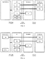
- Figs. 2 and 3 show examples for two different implementation options: In Fig. 2 the NAS entity for the Wearable is residing in the UE; in Fig. 3 the Wearable has its own NAS entity implemented.
- the Wearable has also its own USIM application.
- this could be an embedded USIM (eUSIM) that is inseparably mounted to the circuitry of the Wearable.
- eUSIM embedded USIM
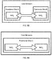
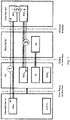
- Figs. 2 and 3 show both NAS entities residing in the same core network domain. This doesn't have to be the case in all deployment scenarios: Both NAS entities may be located in different core network domains, in different MMEs, or even in different functional network slices (cf. Figs. 4 to 6 ).
- Step 2 depicts the inventive exchange of NAS specific data between the two NAS entities involved on the network side.
- a uni-directional or bi-directional capability exchange may take place whenever a Wearable is trying to newly register with a UE. For instance, while requesting information from the UE in order to find out, whether the UE is offering any relaying services, the Wearable may let the UE know that:
- the UE may indicate to the Wearable that:
- the UE could transmit the following information related to user preferences and/or subscriber settings and/or network policies to the Wearable either in the same response message or in a subsequent (pair of) message(s):
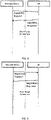
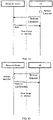
- Figure 8 shows an exemplary message sequence chart between a Wearable and a UE for the mutual capability exchange.
- Possible message structures for the Request/Response pair of Figure 8 are given in the Tables 1 and 2 below.
- Table 1 shows an example of a Capability Request message while table 2 shows an example of a Capability Response message.
- Table 1 Information Element Description Presence Message Header Protocol Version Identifying the protocol version used.
- Mandatory Message ID Unique identifier of this message.
- Mandatory Message Type Identifying this message as a "Capability Request" message (in the scope of the novel short range air interface profile).
- Mandatory Originator Short Range Address Identifying the originating device e.g. the BT Device ID of the Wearable.
- Mandatory Recipient Short Range Address Identifying the intended recipient of this message e.g. the BT Device ID of the UE.
- Mandatory Originator Device Class Specifying the type of the transmitting device, e.g. "Wearable”.
- Capabilities Container > NAS Implementation Details Indicating whether the originating device has implemented a NAS entity of its own, for example: Mandatory • true; • false. > Subscriber Identity Details Indicating whether the originating device has inserted or embedded a Universal Subscriber Identity Module (USIM), for example: Mandatory • true; • false.
- USIM Universal Subscriber Identity Module
- ⁇ ⁇ ⁇ Auxiliary Information User ID Information about the user.
- Optional ⁇ ⁇ ⁇ Table 2 Information Element Description Presence Message Header Protocol Version Identifying the protocol version used.
- Mandatory Message ID Unique identifier of this message.
- Mandatory Message Type Identifying this message as a "Capability Response" message (in the scope of the novel short range air interface profile).
- Mandatory Originator Short Range Address Identifying the originating device, e.g. the BT Device ID of the UE.
- Mandatory Recipient Short Range Address Identifying the intended recipient of this message e.g. the BT Device ID of the Wearable.
- Mandatory Originator Device Class Specifying the type of the transmitting device, e.g. "UE".
- Mandatory Capabilities Container Relaying Indicating whether the originating device supports relaying functionality for Wearables, for example: Mandatory • true; • false. > NAS Implementation Details Indicating whether the originating device has implemented a spare NAS entity for Wearables, for example: Mandatory • true; • false. > Subscriber Identity Details Indicating whether the originating device has inserted or embedded a spare Universal Subscriber Identity Module (USIM) for Wearables, for example: Mandatory • true; • false.
- Auxiliary Information > User ID Indicating whether Wearable and UE are operated by the same user.
- Optional ⁇ ⁇ ⁇ User Preferences Container > Building a Personal Area Network (PAN). For example: Optional • granted; • not granted.
- ⁇ ⁇ ⁇ Network Policies Container Maximum number of Wearables For example: Optional • at most one; • up to two; • up to three; • etc. ⁇ ⁇ ⁇ Subscriber Settings Container > Network Policies For example, maximum data rate that can be assigned for Wearables: Optional • at most 500 kbit/s; • at most 1 Mbit/s; • at most 2 Mbit/s; • etc. ⁇ ⁇ ⁇
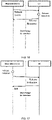
- Fig. 9 shows an exemplary message sequence chart between a Wearable and a UE for this negotiation process. More than one iteration may be required. It is also possible that a counter proposal is part of the negotiation response message.
- the negotiation process is initiated by the Wearable. Alternatively, the process may be initiated by the UE. Possible message structures for the Negotiation Proposal/Response pair of Fig. 9 are skipped for the sake of brevity.
- a Wearable and a UE that is offering a relaying function into an MNO's core network may be first enabled to mutually exchange their capabilities and then to establish, terminate or suspend a (logical) connection for the Wearable into an MNO's core network.
- User preferences, individual subscriber settings, and general network policies can also be take into account in scope of the message exchange framework disclosed.
- the status of the communication between UE and the corresponding cellular mobile communication network (e.g., a cellular communication network operating according to 3GPP LTE or LTE-Advanced) will influence the (potential) communication of the Wearable.
- a cellular mobile communication network e.g., a cellular communication network operating according to 3GPP LTE or LTE-Advanced
- “Status Indication” messages may be exchanged from the UE to the Wearable as part of the message exchange profile at least during the initial phase of signalling.
- Figure 10 shows an exemplary message sequence chart between a UE and a Wearable initiated by the UE to inform the Wearable about recent changes of the UE's communication status.
- the transmission of the "Status Indication” message is triggered when an event has been detected. Possible events may comprise a loss of the cellular link (such as "Radio Link Failure” in LTE), a degradation or increase of the data rate over the cellular link, an RRC state transition in the UE, or similar.
- the UE could also be configured to send "Status Indication" messages on a regular basis.
- the Wearable may be informed over the short range interface about upcoming (i.e. imminent) changes on the cellular link in order to allow the Wearable to perform data transmissions in a more efficient way. For example, a coordinated (i.e. synchronized) transmission of keep-alive message to various application servers on the internet will reduce the need for the UE to continuously reconnect to the cellular network (i.e., to continuously perform state transitions) for small data packets. Therefore, schedules for data transmissions may be sent as part of the message exchange profile to increase efficiency of connecting a Wearable to a UE. There are different options to achieve this:
- Table 3 is an example of a Status Indication message while table 4 is an example of an Acknowledgement message.
- Mandatory Message ID Unique identifier of this message.
- Mandatory Message Type Identifying this message as a "Status Indication" message (in the scope of the novel short range air interface profile).
- Mandatory Originator Short Range Address Identifying the originating device, e.g. the BT Device ID of the UE.
- Mandatory Recipient Short Range Address Identifying the intended recipient of this message, e.g.
- Mandatory Indication Type Specifying the type of the indication, e.g. Mandatory • First Indication; • Event based update; • Regular update; • RRC Schedule; • DRX pattern.
- Change Container > RRC State Transition Indicating the direction of an RRC state transition in the UE, for example: Optional • from IDLE to CONNECTED; • from SUSPENDED to CONNECTED; • from CONNECTED to IDLE • from CONNECTED to SUSPENDED; • from SUSPENDED to IDLE; • from IDLE to SUSPENDED.
- PLMN Indicating the PLMN the UE is currently registered with e.g.: Optional • MCC + MNC (six digits); • None.
- Data Rate for all Wearables
- the maximum data rate that can be assigned for all Wearables connected to the UE Optional • 500 kbit/s; • 1 Mbit/s; • 2 Mbit/s; • etc.
- Roaming Indicating whether the UE is roaming for example: Optional • true; • false.
- Support of Mobile Data Indicating the current status of the "mobile data" option in the UE for example: Optional • activated; • deactivated.
- the Wearable may be informed about current and future communication state changes of the UE's connection to the network.
- Per packet priority and/or delay tolerance may be provided from the Wearable to the UE for efficient data transfer to the network.
- the Wearable can trigger the UE to perform a registration of the Wearable at the cellular network.
- the trigger may also be implicit, e.g. the registration of the Wearable at the UE may automatically trigger the UE to register the Wearable at the core network.
- a specific registration request message may be provided to the UE containing
- the UE If the UE has full control of the NAS entity for the Wearable, it will create and transmit a registration message via the cellular connection to the network it currently uses taking into account the information received from the Wearable and filling-in information related to the UE and its currently established network connection.
- the Wearable has a NAS entity implemented on its own and generates the registration message that is then provided to the UE containing above information.
- the UE may fill-in information missing in the message and transmit the message via the cellular air interface.
- the Wearable may be enabled to send a "Registration Request" message to the UE via the novel message exchange profile thereby triggering the UE to set-up a cellular connection (for instance, a wireless connection according to 3GPP LTE or LTE-Advanced) to the core network.
- a cellular connection for instance, a wireless connection according to 3GPP LTE or LTE-Advanced
- Fig. 11 is showing an example message pair.
- Tables 5 and 6 below are giving possible message structures for the Registration Request/Registration Confirmation pair of messages according to Fig. 11 .
- Table 5 is an example of a Registration Request message while table 6 is an example of a Registration Confirmation message.
- Mandatory Message ID Unique identifier of this message.
- Mandatory Message Type Identifying this message as a "Registration Request" message (in the scope of the novel short range air interface profile).
- Mandatory Originator Short Range Address Identifying the originating device, e.g. the BT Device ID of the Wearable.
- Mandatory Recipient Short Range Address Identifying the intended recipient of this message, e.g. the BT Device ID of the UE.
- PDN Packet Data Network
- Optional > Authentication Data Authentication related information, if the UE generates NAS messages on behalf of the Wearable while the Wearable has the SIM or USIM (as described above).
- Mandatory Message ID Unique identifier of this message.
- Mandatory Message Type Identifying this message as an "Registration Confirmation" message (in the scope of the novel short range air interface profile).
- Mandatory Originator Short Range Address Identifying the originating device, e.g. the BT Device ID of the UE.
- Mandatory Recipient Short Range Address Identifying the intended recipient of this message, e.g. the BT Device ID of the Wearable.
- Mandatory Feedback Container > Acknowledgement Indicating whether the corresponding registration request was received successfully by the UE, for example: Mandatory • true; • false. > In reply to Echoing back the identifier of the preceding "Registration Request" message.
- the Wearable can trigger the UE to set-up the Wearable's (logical) connection to the network.
- the Wearable may be enabled to send a "Keep Up Request" message to the UE via the novel message exchange profile. Once this message is received by the UE, the UE is expected to keep the current cellular connection into the Mobile Network Operator's core network (for instance, a wireless connection according to 3GPP LTE or LTE-Advanced) alive a little bit longer on behalf of the Wearable.
- Fig. 12 is showing an example message pair.
- Tables 7 and 8 below give possible message structures for the Keep Up Request/Keep Up Response pair of messages according to Fig. 12 .
- Table 7 is an example of a Keep-Up Request message while table 8 is an example of a Keep-Up Response message.
- Mandatory Message ID Unique identifier of this message.
- Mandatory Message Type Identifying this message as a "Keep Up Request" message (in the scope of the novel short range air interface profile).
- Mandatory Originator Short Range Address Identifying the originating device, e.g. the BT Device ID of the Wearable.
- Mandatory Recipient Short Range Address Identifying the intended recipient of this message, e.g. the BT Device ID of the UE.
- Mandatory Container Projected Time Span Indicating a time span (calculated or predicted) by the Wearable, e.g.: Optional • 500ms, 1s, 2s, etc. > Traffic Direction Indicating the direction of the traffic expected to occur by the Wearable, for example: Optional • downlink; • uplink; • both.
- Mandatory Message ID Unique identifier of this message.
- Mandatory Message Type Identifying this message as an "Keep Up Response" message (in the scope of the novel short range air interface profile).
- Mandatory Originator Short Range Address Identifying the originating device, e.g. the BT Device ID of the UE.
- Mandatory Recipient Short Range Address Identifying the intended recipient of this message e.g. the BT Device ID of the Wearable.
- Mandatory Feedback Container Acknowledgement Indicating whether the corresponding keep up request was received successfully by the UE, for example: Mandatory • true; • false. > In reply to Echoing back the identifier of the preceding "Keep Up Request" message.
- Mandatory > Time Span Indicating a time span determined (or granted) by the UE, e.g.: Optional • 500ms, 1s, 2s, etc.
- the Wearable can ask the UE to keep up the Wearable's (logical) connection to the network a little while longer, as there may be more data available in the Wearables uplink buffer to be sent via the relaying UE, or as the Wearable is expecting an answer (in form of downlink data arriving) from a peer entity.
- Figs. 13 , 14, and 15 show some example message flows between the UE and the Wearable for releasing the network connection for the Wearable.
- Fig. 13 shows some messages that may be used to realize an early release indication procedure.
- the UE informs the Wearable about a planned (or imminent) release of a connection (message type: "Early Release Indication”). If the Wearable is unhappy with what is proposed by the UE, the Wearable may generate a different release proposal, which is sent back (message type: "Early Release Response”) and evaluated by the UE and/or in the core network.
- An early indication of a planned release of the network connection may be desirable, as it allows the Wearable to look for an alternative relaying device to register with, so that it can easily resume the connection later on.
- a connection suspend rather than a connection release operation (looking at it from the network's point of view)
- no detailed message structures are shown for the sake of brevity.
- Fig. 14 the UE, which may (in one embodiment) host the Wearable's NAS entity, informs the Wearable about a successful release of the Wearable's network connection (message type: "Release Indication”). The Wearable simply acknowledges this message (message type: "Ack”). For this variant no detailed message structures are shown either.
- the message flow of Fig. 14 may follow right after the message flow of Fig. 13 ; and the "Proposal Evaluation" of Fig. 13 may result in (or, merge with) the "Release Execution” of Fig. 14 .
- the Wearable which may (in another embodiment) host its own NAS entity, is requested by the UE to release its network connection (message type: "Release Request”). The Wearable may then release its network connection and confirm a successful connection release (message type: "Release Confirmation”).
- the messages shown in Fig. 15 may follow right after the message flow of Fig. 13 .
- the "Release Request" message in Fig. 15 may contain parameters that were calculated or determined during the "Proposal Evaluation" of Fig. 13 .
- Table 9 is an example of a Release Request message while table 10 is an example of a Release Response message.
- Mandatory Message ID Unique identifier of this message.
- Mandatory Message Type Identifying this message as a "Release Request" message (in the scope of the novel short range air interface profile).
- Mandatory Originator Short Range Address Identifying the originating device, e.g. the BT Device ID of the UE.
- Mandatory Recipient Short Range Address Identifying the intended recipient of this message, e.g. the BT Device ID of the Wearable.
- Mandatory Release Command Container > Release Instruction Indicating the type of the connection release command, e.g.: Optional • immediate; • deferred; • cancelled. > Delay time Indicating the granted duration for the delay (if such a delay has been requested by the Wearable), e.g.: Optional • 500ms, 1s, 2s, etc. > Context held for resumption Indicating whether the Wearable's context will be held in the core network (if the Wearable is expected to search for another relaying opportunity, e.g.: Optional • true; • false. > Context ID Identifying the Wearable's context in the core network, e.g.: 8 bytes in length.
- Mandatory Message ID Unique identifier of this message.
- Mandatory Message Type Identifying this message as an "Release Confirmation" message (in the scope of the novel short range air interface profile).
- Mandatory Originator Short Range Address Identifying the originating device, e.g. the BT Device ID of the Wearable.
- Mandatory Recipient Short Range Address Identifying the intended recipient of this message, e.g. the BT Device ID of the UE.
- Mandatory Confirmation Container Acknowledgement Indicating whether the corresponding release request was received successfully by the UE, for example: Mandatory • true; • false. > Command execution Indicating whether the release command received was executed, e.g.: Optional • true; • false. > In reply to Echoing back the identifier of the preceding "Release Request" message.
- the early indication can be part of the above-mentioned "communication status indication” and/or “schedule exchange” from the UE to the Wearable.
- the UE may initiate the release process of the Wearable's (logical) connection to the network.
- the Wearable may be informed in advance about a planned release of the Wearable's (logical) connection to the network and may either execute the release operation itself (e.g., if the relevant NAS entity is residing inside the Wearable), or respond to the UE with a release suspension proposal (e.g., if the relevant NAS entity is residing inside the UE).
- the message flow would look like the one given in Fig. 17 .
- the Wearable is informing the UE about a terminated connection into the MNO's core network (i.e. about an already executed release of a logical connection at NAS layer and the release of its network registration at the MME, respectively).
- the MNO's core network i.e. about an already executed release of a logical connection at NAS layer and the release of its network registration at the MME, respectively.
- no detailed message structures are shown for the sake of brevity.
- Fig. 16 shows an example message flow between the Wearable and the UE with respect to requesting the UE to terminate a network connection for the Wearable.
- the Wearable simply requests from the UE over the short range interface to release its network registration at the MME (message type "Release Query"), so that the UE may then generate and transmit a registration release request to the MME on behalf of the Wearable ("Release Execution").
- the UE may inform the Wearable about the outcome of this effort by means of the "Release Response” message.
- Some detailed message structures for the example message flow of Figure 16 are given in the Tables 11 and 12.
- Table 11 is an example of a Release Query message while table 12 is an example of a Release Response message.
- Mandatory Message ID Unique identifier of this message.
- Mandatory Message Type Identifying this message as a "Release Query" message (in the scope of the novel short range air interface profile).
- Mandatory Originator Short Range Address Identifying the originating device, e.g. the BT Device ID of the Wearable.
- Mandatory Recipient Short Range Address Identifying the intended recipient of this message, e.g. the BT Device ID of the UE.
- Mandatory Release Command Container > Release Instruction Indicating the type of the connection release command, e.g.: Optional • immediate; • deferred. > Delay time Indicating the desired delay time (if such a delay has been requested by the Wearable), e.g.: Optional • 500ms, 1s, 2s, etc.
- Mandatory Recipient Short Range Address Identifying the intended recipient of this message e.g. the BT Device ID of the Wearable.
- Mandatory Confirmation Container Acknowledgement Indicating whether the corresponding release query was received successfully by the UE, for example: Optional • true; • false. > Command execution Indicating whether the release command received was executed, e.g.: Optional • true; • false. > Context held for resumption Indicating whether the Wearable's context will be held in the core network, e.g.: Optional • true; • false. > Context ID Identifying the Wearable's context in the core network, e.g.: 8 bytes in length.
- Optional Context storage duration Indicating the duration for the above, e.g.: 500ms, 1s, 2s, etc.
- a Wearable's context is stored on the network side for a future re-activation of a suspended logical connection (e.g., at NAS layer)
- a Context ID (as described for instance within the scope of the "Release Request” message according to Table 9 and the "Release Response” message according to Table 12).
- This Context ID may be used by the Wearable at a later point in time when it re-activates the suspended connection. Doing so allows faster re-activation of a suspended connection when the Wearable is changing (or substituting) a UE with relaying capabilities.
- NAS in the Wearable setup could mean that the Wearable performs Session Management, Registration, and Security while the UE always performs Mobility (and some other things).
- the various information elements described in connection with the various messages may be grouped in other ways. For example, they may be collated in a new or already existing hierarchical structure, or grouped together with other information elements, for instance in form of a list or a container.
- SUSPENDED vs. IDLE shall not be understood as restricting this invention to an LTE environment.
- other UE states may be defined.
- the same, similar, or other RRC states may be defined and supported by UE implementations.
- BT may represent a preferred embodiment of the present invention
- the wireless short range technology supported by the wearable device and the cellular communication device for the exchange of messages as described herein doesn't have to be (based on) BT in all cases.
- Other wireless short range technologies, such as WiFi, may also be suited to support the methods described in this document.
- the wearable device itself may have implemented a(t least one) cellular modem, so it may take on the form of a cellular communication device.
- the radio access technologies supported by the cellular modem(s) of the wearable device and the cellular modem(s) of the cellular communication device may be the same or different.
- a wearable device may also be a (form of) cellular communication terminal, generally referred to as a mobile communication device, such as a mobile phone.
Landscapes
- Engineering & Computer Science (AREA)
- Computer Networks & Wireless Communication (AREA)
- Signal Processing (AREA)
- Computer Security & Cryptography (AREA)
- Mobile Radio Communication Systems (AREA)
Claims (13)
- Verfahren für eine mobile Kommunikationsvorrichtung (UE) zur Kommunikation mit einer Benutzervorrichtung (Wearable Device) über eine Kurzstreckenfunkschnittstellenverbindung, wobei die mobile Kommunikationsvorrichtung als Relaisknoten zur Ermöglichung einer Verbindung der Benutzervorrichtung mit einem Kernnetzwerk (Core Network) dient, wobei das Verfahren Verhandeln von Fähigkeiten einer Vermittlungsebene (Non-access-Stratum, NAS) zum Verbinden der Benutzervorrichtung mit der mobilen Kommunikationsvorrichtung und zum Betreiben der Benutzervorrichtung unter Verwendung der mobilen Kommunikationsvorrichtung als den Relaisknoten umfasst, dadurch gekennzeichnet, dass die mobile Kommunikationsvorrichtung das Kernnetzwerk veranlasst, zumindest einen Benutzervorrichtungskontext während des Freigabevorgangs einer Verbindung zwischen der Benutzervorrichtung und dem Kernnetzwerk aktiv zu halten.
- Verfahren nach Anspruch 1, wobei die Benutzervorrichtung und die mobile Kommunikationsvorrichtung ihre NAS-Fähigkeiten gegenseitig austauschen und dann die Verbindung der Benutzervorrichtung mit dem Kernnetzwerk herstellen.
- Verfahren nach Anspruch 2, wobei zumindest eines von Benutzereinstellungen, individuellen Teilnehmereinstellungen und allgemeinen Netzwerkrichtlinien in dem gegenseitigen Austausch von NAS-Fähigkeiten übermittelt werden.
- Verfahren nach einem der vorstehenden Ansprüche, wobei die mobile Kommunikationsvorrichtung die Benutzervorrichtung über aktuelle und zukünftige Änderungen des Kommunikationsstatus einer Verbindung der Benutzervorrichtung mit dem Kernnetzwerk informiert.
- Verfahren nach einem der vorstehenden Ansprüche, wobei die Benutzervorrichtung zumindest eine Paketprioritätsinformation und Verzögerungstoleranzinformation für die mobile Kommunikationsvorrichtung bereitstellt.
- Verfahren nach einem der vorstehenden Ansprüche, wobei die Benutzervorrichtung die mobile Kommunikationsvorrichtung veranlasst, die Verbindung der Benutzervorrichtung mit dem Kernnetzwerk herzustellen.
- Verfahren nach einem der vorstehenden Ansprüche, wobei die Benutzervorrichtung eine Nachricht an die mobile Kommunikationsvorrichtung übermittelt, in welcher von der mobilen Kommunikationsvorrichtung angefordert wird, die Verbindung der Benutzervorrichtung mit dem Kernnetzwerk beizubehalten.
- Verfahren nach Anspruch 7, wobei die Nachricht, in welcher von der mobilen Kommunikationsvorrichtung angefordert wird, die Verbindung der Benutzervorrichtung mit dem Kernnetzwerk beizubehalten, übermittelt wird, wenn die Benutzervorrichtung in einem Puffer Daten gespeichert hat, welche darauf warten, gesendet zu werden, oder Downlink-Daten erwartet werden.
- Verfahren nach einem der vorstehenden Ansprüche, wobei die mobile Kommunikationsvorrichtung eine Freigabe der Verbindung der Benutzervorrichtung mit dem Kernnetzwerk initiiert.
- Verfahren nach Anspruch 9, wobei die Benutzervorrichtung im Voraus über eine geplante Freigabe der Verbindung der Benutzervorrichtung mit dem Kernnetzwerk informiert wird.
- Verfahren nach einem der vorstehenden Ansprüche, wobei die Benutzervorrichtung eine Anforderung an die mobile Kommunikationsvorrichtung übermittelt, die Verbindung der Benutzervorrichtung mit dem Kernnetzwerk freizugeben.
- Verfahren nach einem der vorstehenden Ansprüche, wobei die mobile Kommunikationsvorrichtung die Benutzervorrichtung mit einem Kontextidentifikator versieht, welcher in der Benutzervorrichtung zur Verwendung zu einem späteren Zeitpunkt gespeichert werden kann.
- Verfahren nach einem der vorstehenden Ansprüche, wobei die Benutzervorrichtung den gespeicherten Kontextidentifikator verwendet, wenn sie versucht, eine Verbindung mit einem Kernnetzwerk über eine andere mobile Kommunikationsvorrichtung zu reaktivieren.
Priority Applications (1)
| Application Number | Priority Date | Filing Date | Title |
|---|---|---|---|
| EP22187135.3A EP4149125A1 (de) | 2016-11-03 | 2017-11-03 | Nachrichtenaustausch für wearable-vorrichtungen |
Applications Claiming Priority (2)
| Application Number | Priority Date | Filing Date | Title |
|---|---|---|---|
| EP16197097 | 2016-11-03 | ||
| PCT/EP2017/078199 WO2018083246A1 (en) | 2016-11-03 | 2017-11-03 | Message exchange for wearable devices |
Related Child Applications (1)
| Application Number | Title | Priority Date | Filing Date |
|---|---|---|---|
| EP22187135.3A Division EP4149125A1 (de) | 2016-11-03 | 2017-11-03 | Nachrichtenaustausch für wearable-vorrichtungen |
Publications (2)
| Publication Number | Publication Date |
|---|---|
| EP3535954A1 EP3535954A1 (de) | 2019-09-11 |
| EP3535954B1 true EP3535954B1 (de) | 2022-08-03 |
Family
ID=57280999
Family Applications (2)
| Application Number | Title | Priority Date | Filing Date |
|---|---|---|---|
| EP17797300.5A Active EP3535954B1 (de) | 2016-11-03 | 2017-11-03 | Nachrichtenaustausch für tragbare vorrichtungen |
| EP22187135.3A Pending EP4149125A1 (de) | 2016-11-03 | 2017-11-03 | Nachrichtenaustausch für wearable-vorrichtungen |
Family Applications After (1)
| Application Number | Title | Priority Date | Filing Date |
|---|---|---|---|
| EP22187135.3A Pending EP4149125A1 (de) | 2016-11-03 | 2017-11-03 | Nachrichtenaustausch für wearable-vorrichtungen |
Country Status (8)
| Country | Link |
|---|---|
| US (1) | US20190281127A1 (de) |
| EP (2) | EP3535954B1 (de) |
| CN (2) | CN109906596B (de) |
| BR (1) | BR112019006191A2 (de) |
| ES (1) | ES2927063T3 (de) |
| PL (1) | PL3535954T3 (de) |
| RU (2) | RU2754944C2 (de) |
| WO (1) | WO2018083246A1 (de) |
Families Citing this family (16)
| Publication number | Priority date | Publication date | Assignee | Title |
|---|---|---|---|---|
| US10924912B2 (en) * | 2017-01-06 | 2021-02-16 | Lg Electronics Inc. | Method for transmitting and receiving data through relay in wireless communication system and apparatus therefor |
| WO2019120477A1 (en) * | 2017-12-18 | 2019-06-27 | Motorola Mobility Llc | Indicating a network for a remote unit |
| GB2586232B (en) | 2019-08-09 | 2021-10-20 | Prevayl Ltd | Garment, server and method |
| GB2594898B (en) * | 2019-08-09 | 2022-03-16 | Prevayl Innovations Ltd | Garment, server and method |
| WO2021040423A1 (ko) * | 2019-08-27 | 2021-03-04 | 엘지전자 주식회사 | 설정 업데이트와 관련된 통신 |
| EP4024966B1 (de) * | 2019-10-11 | 2024-12-04 | Lg Electronics Inc. | Verfahren zur übertragung von einem sidelink-signal in einem drahtloskommunikationssystem |
| US11472455B2 (en) * | 2020-03-04 | 2022-10-18 | Hyperloop Technologies, Inc. | System and method for network communication within a hyperloop bogie during a critical period of time |
| CN114339939B (zh) * | 2020-10-12 | 2025-02-25 | 维沃移动通信有限公司 | 非激活态配置方法、装置及通信设备 |
| BR112023020075A2 (pt) * | 2021-03-29 | 2024-01-23 | Interdigital Patent Holdings Inc | Método para radiobusca eficiente para equipamentos de usuário para retransmissões de rede |
| US20240129693A1 (en) * | 2022-10-18 | 2024-04-18 | At&T Intellectual Property I, L.P. | Public safety answering point (psap) access from a private core network |
| US12355770B2 (en) * | 2023-10-03 | 2025-07-08 | strongDM, Inc. | Identity and activity based network security policies |
| US12411783B1 (en) * | 2024-02-29 | 2025-09-09 | Oura Health Oy | Techniques for automated serial device integration to microcontroller |
| US12242599B1 (en) | 2024-09-27 | 2025-03-04 | strongDM, Inc. | Fine-grained security policy enforcement for applications |
| US12348519B1 (en) | 2025-02-07 | 2025-07-01 | strongDM, Inc. | Evaluating security policies in aggregate |
| US12432242B1 (en) | 2025-03-28 | 2025-09-30 | strongDM, Inc. | Anomaly detection in managed networks |
| US12603921B1 (en) | 2025-11-19 | 2026-04-14 | strongDM, Inc. | Indexing entities and attributes for policy enforcement |
Citations (1)
| Publication number | Priority date | Publication date | Assignee | Title |
|---|---|---|---|---|
| EP1897243B1 (de) * | 2005-06-30 | 2012-10-31 | Nokia Corporation | Rfid-optimierte kapazitätsverhandlung |
Family Cites Families (34)
| Publication number | Priority date | Publication date | Assignee | Title |
|---|---|---|---|---|
| EP2206392B1 (de) * | 2007-10-24 | 2012-08-08 | Nokia Siemens Networks Oy | Verfahren und vorrichtung zur bereitstellung einer rahmenstruktur zur unterstützung verschiedener betriebsmodi |
| EP2428093B1 (de) * | 2009-05-08 | 2020-04-01 | Telefonaktiebolaget LM Ericsson (publ) | Lokales umschalten |
| CN102378313A (zh) * | 2010-08-24 | 2012-03-14 | 中兴通讯股份有限公司 | 移动性管理实体的选择方法及中继节点 |
| US20120238208A1 (en) | 2011-03-17 | 2012-09-20 | Maik Bienas | Mobile radio communication devices and servers |
| US20120250601A1 (en) | 2011-03-28 | 2012-10-04 | Hyung-Nam Choi | Communication terminal, method for exchanging data, communication device and method for establishing a communication connection |
| US8879980B2 (en) * | 2011-05-05 | 2014-11-04 | Intel Mobile Communications GmbH | Mobile radio communication devices, mobile radio communication network devices, methods for controlling a mobile radio communication device, and methods for controlling a mobile radio communication network device |
| RU111940U1 (ru) * | 2011-07-19 | 2011-12-27 | Открытое акционерное общество "Московское конструкторское бюро "Компас" | Система навигации, регистрации, мониторинга, охраны и контроля стационарных и мобильных объектов |
| US8682243B2 (en) * | 2011-07-27 | 2014-03-25 | Intel Mobile Communications GmbH | Network selection device and method for selecting a communication network |
| GB2493240B (en) * | 2011-07-29 | 2016-01-20 | Sca Ipla Holdings Inc | Mobile communications network, infrastructure equipment and method |
| BR112014000454B1 (pt) * | 2011-07-29 | 2022-05-24 | Sca Ipla Holdings Inc | Terminal de comunicações móveis, e, método de operar um terminal de comunicações móveis |
| GB2493348A (en) * | 2011-07-29 | 2013-02-06 | Intellectual Ventures Holding 81 Llc | Mobile communications terminal with simplified handover |
| EP2557889B1 (de) * | 2011-08-12 | 2019-07-17 | BlackBerry Limited | Vereinfachte ue- + enb-nachrichtenübermittlung |
| EP2783539B1 (de) * | 2011-11-22 | 2016-03-02 | SCA IPLA Holdings Inc. | System und verfahren für funkrufe an endgeräte im offline-zustand |
| US20130137469A1 (en) | 2011-11-30 | 2013-05-30 | Intel Mobile Communications GmbH | Method for transmitting an opportunistic network related message |
| CN102573066B (zh) * | 2012-02-02 | 2016-08-03 | 电信科学技术研究院 | 一种传输rn信息、寻呼ue的方法及装置 |
| KR101611965B1 (ko) * | 2012-10-05 | 2016-04-12 | 엘지전자 주식회사 | 무선 통신 시스템에서 다중 우선순위 제어 방법 및 장치 |
| WO2014069748A1 (ko) * | 2012-11-01 | 2014-05-08 | 엘지전자 주식회사 | 무선 통신 시스템에서 ran 자원 관리 방법 및 장치 |
| US9900832B2 (en) * | 2012-11-07 | 2018-02-20 | Lg Electronics Inc. | Method and an apparatus for access network selection in a wireless communication system |
| US8989807B2 (en) | 2013-02-28 | 2015-03-24 | Intel Mobile Communications GmbH | Communication terminal device, communication device, communication network server and method for controlling |
| US9622035B2 (en) | 2013-07-04 | 2017-04-11 | Lg Electronics Inc. | Relay control method for proximity service and device therefor |
| US20150142982A1 (en) * | 2013-11-15 | 2015-05-21 | Microsoft Corporation | Preservation of connection session |
| WO2015102445A1 (ko) * | 2014-01-05 | 2015-07-09 | 엘지전자 주식회사 | 근접 서비스 기반의 그룹 통신을 중계하는 방법 및 사용자 장치 |
| CN106105382A (zh) * | 2014-02-19 | 2016-11-09 | 康维达无线有限责任公司 | 用于系统间移动性的服务网关扩展 |
| KR102016644B1 (ko) * | 2014-02-23 | 2019-08-30 | 삼성전자주식회사 | 전자 장치의 기능 및 리소스 운용 방법 |
| US9801120B2 (en) * | 2014-05-30 | 2017-10-24 | Apple Inc. | Client-initiated tethering for electronic devices |
| CN105530038B (zh) * | 2014-09-30 | 2019-01-08 | 中国移动通信集团公司 | 一种中继装置、中继服务器及中继方法 |
| CN104468312B (zh) * | 2014-11-20 | 2019-03-15 | 中兴通讯股份有限公司 | 一种无线中继站及其接入核心网的方法和系统 |
| US10667321B2 (en) * | 2015-02-09 | 2020-05-26 | Intel IP Corporation | Evolved Node-B, user equipment, and methods for transition between idle and connected modes |
| CN108307691B (zh) * | 2015-03-18 | 2021-07-06 | 日本电气株式会社 | 通信系统 |
| US9980304B2 (en) * | 2015-04-03 | 2018-05-22 | Google Llc | Adaptive on-demand tethering |
| JP6985152B2 (ja) * | 2015-04-08 | 2021-12-22 | インターデイジタル パテント ホールディングス インコーポレイテッド | デバイスツーデバイス(d2d)通信のモバイル中継器の実現 |
| CN107637162B (zh) * | 2015-05-14 | 2022-05-10 | 苹果公司 | Ue到网络中继发起和配置 |
| CN106686674B (zh) * | 2015-11-05 | 2019-12-13 | 索尼公司 | 无线通信系统中的电子设备和无线通信方法 |
| EP3229549B1 (de) * | 2016-04-08 | 2018-11-21 | Panasonic Intellectual Property Corporation of America | Verfahren zur gruppierung von tragbaren vorrichtungen mit lte-master-benutzergeräten |
-
2017
- 2017-11-03 EP EP17797300.5A patent/EP3535954B1/de active Active
- 2017-11-03 WO PCT/EP2017/078199 patent/WO2018083246A1/en not_active Ceased
- 2017-11-03 CN CN201780068181.3A patent/CN109906596B/zh active Active
- 2017-11-03 BR BR112019006191A patent/BR112019006191A2/pt not_active IP Right Cessation
- 2017-11-03 ES ES17797300T patent/ES2927063T3/es active Active
- 2017-11-03 RU RU2019117012A patent/RU2754944C2/ru active
- 2017-11-03 CN CN202310027864.1A patent/CN116033369B/zh active Active
- 2017-11-03 PL PL17797300.5T patent/PL3535954T3/pl unknown
- 2017-11-03 RU RU2021123910A patent/RU2021123910A/ru unknown
- 2017-11-03 EP EP22187135.3A patent/EP4149125A1/de active Pending
- 2017-11-03 US US16/345,497 patent/US20190281127A1/en not_active Abandoned
Patent Citations (1)
| Publication number | Priority date | Publication date | Assignee | Title |
|---|---|---|---|---|
| EP1897243B1 (de) * | 2005-06-30 | 2012-10-31 | Nokia Corporation | Rfid-optimierte kapazitätsverhandlung |
Non-Patent Citations (1)
| Title |
|---|
| ZTE: "Considerations on the working scope of R14 feD2D", vol. RAN WG2, no. Dubrovnik, Croatia; 20160411 - 20160415, 1 April 2016 (2016-04-01), XP051082087, Retrieved from the Internet <URL:http://www.3gpp.org/ftp/tsg_ran/WG2_RL2/TSGR2_93bis/Docs/> [retrieved on 20160401] * |
Also Published As
| Publication number | Publication date |
|---|---|
| RU2019117012A3 (de) | 2020-12-11 |
| CN116033369A (zh) | 2023-04-28 |
| CN109906596A (zh) | 2019-06-18 |
| US20190281127A1 (en) | 2019-09-12 |
| RU2754944C2 (ru) | 2021-09-08 |
| ES2927063T3 (es) | 2022-11-02 |
| RU2021123910A (ru) | 2021-09-27 |
| WO2018083246A1 (en) | 2018-05-11 |
| EP3535954A1 (de) | 2019-09-11 |
| BR112019006191A2 (pt) | 2019-06-18 |
| EP4149125A1 (de) | 2023-03-15 |
| CN109906596B (zh) | 2023-01-10 |
| PL3535954T3 (pl) | 2022-11-28 |
| CN116033369B (zh) | 2025-04-29 |
| RU2019117012A (ru) | 2020-12-03 |
Similar Documents
| Publication | Publication Date | Title |
|---|---|---|
| EP3535954B1 (de) | Nachrichtenaustausch für tragbare vorrichtungen | |
| US11510264B2 (en) | System and method for network access using a relay | |
| WO2022052092A1 (en) | Connection establishment for a layer 2 ue-to-network relay | |
| EP2680619A2 (de) | Kommunikationssystem und Vorrichtung für statusabhängige mobile Dienste | |
| JP2019512990A (ja) | モバイル通信システムにおけるデバイスツーデバイス中継サービスに基づく通信を提供する装置 | |
| EP3888394B1 (de) | Informieren einer oberen schicht einer sperrungsverminderung für mehrere zugangsklassen | |
| EP3346761B1 (de) | Vorrichtung und verfahren zur handhabung eines paketstroms in mobilität zwischen systemen | |
| CN102204392A (zh) | 将drx的间歇时段用于小区中的直接对等通信 | |
| CN114258104A (zh) | 层2用户设备通过网络中继进行信令传输的方法 | |
| CN116567853A (zh) | 控制用户设备的网络接入 | |
| CN115720717A (zh) | 用于无线通信的方法及设备 | |
| JP2024523569A (ja) | ユーザデバイスのためのページングの管理 | |
| CN117296382A (zh) | 用于侧链路中继通信的方法和装置 | |
| CN113647162A (zh) | 寻呼和多标识模块无线通信装置 | |
| WO2024019061A1 (ja) | 通信装置、基地局及び通信方法 | |
| CN115334693B (zh) | 用于通信的设备 | |
| JP7672577B2 (ja) | サイドリンク通信を管理するための技術 | |
| CN119096622A (zh) | 处理小数据传输 | |
| JP7736203B2 (ja) | 通信装置、基地局及び通信方法 | |
| TWI753326B (zh) | 無線通訊中在擁塞控制下發送用戶資料的方法和裝置 | |
| WO2024019058A1 (ja) | 通信装置、基地局及び通信方法 | |
| WO2024019060A1 (ja) | 通信装置及び通信方法 | |
| US10813145B2 (en) | Method and apparatus for controlling apparatus by using bluetooth technology | |
| WO2024034474A1 (ja) | 通信装置、基地局及び通信方法 | |
| CN120035961A (zh) | 通信方法、终端设备以及网络设备 |
Legal Events
| Date | Code | Title | Description |
|---|---|---|---|
| STAA | Information on the status of an ep patent application or granted ep patent |
Free format text: STATUS: UNKNOWN |
|
| STAA | Information on the status of an ep patent application or granted ep patent |
Free format text: STATUS: THE INTERNATIONAL PUBLICATION HAS BEEN MADE |
|
| PUAI | Public reference made under article 153(3) epc to a published international application that has entered the european phase |
Free format text: ORIGINAL CODE: 0009012 |
|
| STAA | Information on the status of an ep patent application or granted ep patent |
Free format text: STATUS: REQUEST FOR EXAMINATION WAS MADE |
|
| 17P | Request for examination filed |
Effective date: 20190527 |
|
| AK | Designated contracting states |
Kind code of ref document: A1 Designated state(s): AL AT BE BG CH CY CZ DE DK EE ES FI FR GB GR HR HU IE IS IT LI LT LU LV MC MK MT NL NO PL PT RO RS SE SI SK SM TR |
|
| AX | Request for extension of the european patent |
Extension state: BA ME |
|
| DAV | Request for validation of the european patent (deleted) | ||
| DAX | Request for extension of the european patent (deleted) | ||
| STAA | Information on the status of an ep patent application or granted ep patent |
Free format text: STATUS: EXAMINATION IS IN PROGRESS |
|
| 17Q | First examination report despatched |
Effective date: 20210210 |
|
| REG | Reference to a national code |
Ref country code: DE Ref legal event code: R079 Ref document number: 602017060248 Country of ref document: DE Free format text: PREVIOUS MAIN CLASS: H04L0029080000 Ipc: H04W0004000000 |
|
| GRAP | Despatch of communication of intention to grant a patent |
Free format text: ORIGINAL CODE: EPIDOSNIGR1 |
|
| STAA | Information on the status of an ep patent application or granted ep patent |
Free format text: STATUS: GRANT OF PATENT IS INTENDED |
|
| RIC1 | Information provided on ipc code assigned before grant |
Ipc: H04W 48/02 20090101ALN20220302BHEP Ipc: H04L 69/24 20220101ALI20220302BHEP Ipc: H04L 67/563 20220101ALI20220302BHEP Ipc: H04L 67/14 20220101ALI20220302BHEP Ipc: H04W 76/14 20180101ALI20220302BHEP Ipc: H04W 88/04 20090101ALI20220302BHEP Ipc: H04W 84/18 20090101ALI20220302BHEP Ipc: H04W 4/00 20180101AFI20220302BHEP |
|
| INTG | Intention to grant announced |
Effective date: 20220317 |
|
| RIC1 | Information provided on ipc code assigned before grant |
Ipc: H04W 48/02 20090101ALN20220307BHEP Ipc: H04L 69/24 20220101ALI20220307BHEP Ipc: H04L 67/563 20220101ALI20220307BHEP Ipc: H04L 67/14 20220101ALI20220307BHEP Ipc: H04W 76/14 20180101ALI20220307BHEP Ipc: H04W 88/04 20090101ALI20220307BHEP Ipc: H04W 84/18 20090101ALI20220307BHEP Ipc: H04W 4/00 20180101AFI20220307BHEP |
|
| GRAS | Grant fee paid |
Free format text: ORIGINAL CODE: EPIDOSNIGR3 |
|
| GRAA | (expected) grant |
Free format text: ORIGINAL CODE: 0009210 |
|
| STAA | Information on the status of an ep patent application or granted ep patent |
Free format text: STATUS: THE PATENT HAS BEEN GRANTED |
|
| AK | Designated contracting states |
Kind code of ref document: B1 Designated state(s): AL AT BE BG CH CY CZ DE DK EE ES FI FR GB GR HR HU IE IS IT LI LT LU LV MC MK MT NL NO PL PT RO RS SE SI SK SM TR |
|
| REG | Reference to a national code |
Ref country code: AT Ref legal event code: REF Ref document number: 1509719 Country of ref document: AT Kind code of ref document: T Effective date: 20220815 Ref country code: CH Ref legal event code: EP |
|
| REG | Reference to a national code |
Ref country code: DE Ref legal event code: R096 Ref document number: 602017060248 Country of ref document: DE |
|
| REG | Reference to a national code |
Ref country code: IE Ref legal event code: FG4D |
|
| REG | Reference to a national code |
Ref country code: NL Ref legal event code: FP |
|
| REG | Reference to a national code |
Ref country code: ES Ref legal event code: FG2A Ref document number: 2927063 Country of ref document: ES Kind code of ref document: T3 Effective date: 20221102 |
|
| REG | Reference to a national code |
Ref country code: LT Ref legal event code: MG9D |
|
| PG25 | Lapsed in a contracting state [announced via postgrant information from national office to epo] |
Ref country code: SE Free format text: LAPSE BECAUSE OF FAILURE TO SUBMIT A TRANSLATION OF THE DESCRIPTION OR TO PAY THE FEE WITHIN THE PRESCRIBED TIME-LIMIT Effective date: 20220803 Ref country code: RS Free format text: LAPSE BECAUSE OF FAILURE TO SUBMIT A TRANSLATION OF THE DESCRIPTION OR TO PAY THE FEE WITHIN THE PRESCRIBED TIME-LIMIT Effective date: 20220803 Ref country code: PT Free format text: LAPSE BECAUSE OF FAILURE TO SUBMIT A TRANSLATION OF THE DESCRIPTION OR TO PAY THE FEE WITHIN THE PRESCRIBED TIME-LIMIT Effective date: 20221205 Ref country code: NO Free format text: LAPSE BECAUSE OF FAILURE TO SUBMIT A TRANSLATION OF THE DESCRIPTION OR TO PAY THE FEE WITHIN THE PRESCRIBED TIME-LIMIT Effective date: 20221103 Ref country code: LV Free format text: LAPSE BECAUSE OF FAILURE TO SUBMIT A TRANSLATION OF THE DESCRIPTION OR TO PAY THE FEE WITHIN THE PRESCRIBED TIME-LIMIT Effective date: 20220803 Ref country code: LT Free format text: LAPSE BECAUSE OF FAILURE TO SUBMIT A TRANSLATION OF THE DESCRIPTION OR TO PAY THE FEE WITHIN THE PRESCRIBED TIME-LIMIT Effective date: 20220803 Ref country code: FI Free format text: LAPSE BECAUSE OF FAILURE TO SUBMIT A TRANSLATION OF THE DESCRIPTION OR TO PAY THE FEE WITHIN THE PRESCRIBED TIME-LIMIT Effective date: 20220803 |
|
| REG | Reference to a national code |
Ref country code: AT Ref legal event code: MK05 Ref document number: 1509719 Country of ref document: AT Kind code of ref document: T Effective date: 20220803 |
|
| PG25 | Lapsed in a contracting state [announced via postgrant information from national office to epo] |
Ref country code: IS Free format text: LAPSE BECAUSE OF FAILURE TO SUBMIT A TRANSLATION OF THE DESCRIPTION OR TO PAY THE FEE WITHIN THE PRESCRIBED TIME-LIMIT Effective date: 20221203 Ref country code: HR Free format text: LAPSE BECAUSE OF FAILURE TO SUBMIT A TRANSLATION OF THE DESCRIPTION OR TO PAY THE FEE WITHIN THE PRESCRIBED TIME-LIMIT Effective date: 20220803 Ref country code: GR Free format text: LAPSE BECAUSE OF FAILURE TO SUBMIT A TRANSLATION OF THE DESCRIPTION OR TO PAY THE FEE WITHIN THE PRESCRIBED TIME-LIMIT Effective date: 20221104 |
|
| PG25 | Lapsed in a contracting state [announced via postgrant information from national office to epo] |
Ref country code: SM Free format text: LAPSE BECAUSE OF FAILURE TO SUBMIT A TRANSLATION OF THE DESCRIPTION OR TO PAY THE FEE WITHIN THE PRESCRIBED TIME-LIMIT Effective date: 20220803 Ref country code: RO Free format text: LAPSE BECAUSE OF FAILURE TO SUBMIT A TRANSLATION OF THE DESCRIPTION OR TO PAY THE FEE WITHIN THE PRESCRIBED TIME-LIMIT Effective date: 20220803 Ref country code: DK Free format text: LAPSE BECAUSE OF FAILURE TO SUBMIT A TRANSLATION OF THE DESCRIPTION OR TO PAY THE FEE WITHIN THE PRESCRIBED TIME-LIMIT Effective date: 20220803 Ref country code: CZ Free format text: LAPSE BECAUSE OF FAILURE TO SUBMIT A TRANSLATION OF THE DESCRIPTION OR TO PAY THE FEE WITHIN THE PRESCRIBED TIME-LIMIT Effective date: 20220803 Ref country code: AT Free format text: LAPSE BECAUSE OF FAILURE TO SUBMIT A TRANSLATION OF THE DESCRIPTION OR TO PAY THE FEE WITHIN THE PRESCRIBED TIME-LIMIT Effective date: 20220803 |
|
| REG | Reference to a national code |
Ref country code: DE Ref legal event code: R097 Ref document number: 602017060248 Country of ref document: DE |
|
| PG25 | Lapsed in a contracting state [announced via postgrant information from national office to epo] |
Ref country code: SK Free format text: LAPSE BECAUSE OF FAILURE TO SUBMIT A TRANSLATION OF THE DESCRIPTION OR TO PAY THE FEE WITHIN THE PRESCRIBED TIME-LIMIT Effective date: 20220803 Ref country code: EE Free format text: LAPSE BECAUSE OF FAILURE TO SUBMIT A TRANSLATION OF THE DESCRIPTION OR TO PAY THE FEE WITHIN THE PRESCRIBED TIME-LIMIT Effective date: 20220803 |
|
| PLBE | No opposition filed within time limit |
Free format text: ORIGINAL CODE: 0009261 |
|
| STAA | Information on the status of an ep patent application or granted ep patent |
Free format text: STATUS: NO OPPOSITION FILED WITHIN TIME LIMIT |
|
| PG25 | Lapsed in a contracting state [announced via postgrant information from national office to epo] |
Ref country code: MC Free format text: LAPSE BECAUSE OF FAILURE TO SUBMIT A TRANSLATION OF THE DESCRIPTION OR TO PAY THE FEE WITHIN THE PRESCRIBED TIME-LIMIT Effective date: 20220803 Ref country code: AL Free format text: LAPSE BECAUSE OF FAILURE TO SUBMIT A TRANSLATION OF THE DESCRIPTION OR TO PAY THE FEE WITHIN THE PRESCRIBED TIME-LIMIT Effective date: 20220803 |
|
| REG | Reference to a national code |
Ref country code: CH Ref legal event code: PL |
|
| 26N | No opposition filed |
Effective date: 20230504 |
|
| P01 | Opt-out of the competence of the unified patent court (upc) registered |
Effective date: 20230606 |
|
| REG | Reference to a national code |
Ref country code: BE Ref legal event code: MM Effective date: 20221130 |
|
| PG25 | Lapsed in a contracting state [announced via postgrant information from national office to epo] |
Ref country code: LI Free format text: LAPSE BECAUSE OF NON-PAYMENT OF DUE FEES Effective date: 20221130 Ref country code: CH Free format text: LAPSE BECAUSE OF NON-PAYMENT OF DUE FEES Effective date: 20221130 |
|
| PG25 | Lapsed in a contracting state [announced via postgrant information from national office to epo] |
Ref country code: SI Free format text: LAPSE BECAUSE OF FAILURE TO SUBMIT A TRANSLATION OF THE DESCRIPTION OR TO PAY THE FEE WITHIN THE PRESCRIBED TIME-LIMIT Effective date: 20220803 Ref country code: LU Free format text: LAPSE BECAUSE OF NON-PAYMENT OF DUE FEES Effective date: 20221103 |
|
| PG25 | Lapsed in a contracting state [announced via postgrant information from national office to epo] |
Ref country code: IE Free format text: LAPSE BECAUSE OF NON-PAYMENT OF DUE FEES Effective date: 20221103 |
|
| PGFP | Annual fee paid to national office [announced via postgrant information from national office to epo] |
Ref country code: NL Payment date: 20230915 Year of fee payment: 7 |
|
| PG25 | Lapsed in a contracting state [announced via postgrant information from national office to epo] |
Ref country code: BE Free format text: LAPSE BECAUSE OF NON-PAYMENT OF DUE FEES Effective date: 20221130 |
|
| PGFP | Annual fee paid to national office [announced via postgrant information from national office to epo] |
Ref country code: FR Payment date: 20230911 Year of fee payment: 7 |
|
| PGFP | Annual fee paid to national office [announced via postgrant information from national office to epo] |
Ref country code: ES Payment date: 20231212 Year of fee payment: 7 |
|
| PGFP | Annual fee paid to national office [announced via postgrant information from national office to epo] |
Ref country code: TR Payment date: 20231101 Year of fee payment: 7 Ref country code: IT Payment date: 20231010 Year of fee payment: 7 |
|
| PGFP | Annual fee paid to national office [announced via postgrant information from national office to epo] |
Ref country code: PL Payment date: 20231102 Year of fee payment: 7 |
|
| PG25 | Lapsed in a contracting state [announced via postgrant information from national office to epo] |
Ref country code: HU Free format text: LAPSE BECAUSE OF FAILURE TO SUBMIT A TRANSLATION OF THE DESCRIPTION OR TO PAY THE FEE WITHIN THE PRESCRIBED TIME-LIMIT; INVALID AB INITIO Effective date: 20171103 |
|
| PG25 | Lapsed in a contracting state [announced via postgrant information from national office to epo] |
Ref country code: CY Free format text: LAPSE BECAUSE OF FAILURE TO SUBMIT A TRANSLATION OF THE DESCRIPTION OR TO PAY THE FEE WITHIN THE PRESCRIBED TIME-LIMIT Effective date: 20220803 |
|
| PG25 | Lapsed in a contracting state [announced via postgrant information from national office to epo] |
Ref country code: MK Free format text: LAPSE BECAUSE OF FAILURE TO SUBMIT A TRANSLATION OF THE DESCRIPTION OR TO PAY THE FEE WITHIN THE PRESCRIBED TIME-LIMIT Effective date: 20220803 |
|
| PG25 | Lapsed in a contracting state [announced via postgrant information from national office to epo] |
Ref country code: BG Free format text: LAPSE BECAUSE OF FAILURE TO SUBMIT A TRANSLATION OF THE DESCRIPTION OR TO PAY THE FEE WITHIN THE PRESCRIBED TIME-LIMIT Effective date: 20220803 |
|
| PG25 | Lapsed in a contracting state [announced via postgrant information from national office to epo] |
Ref country code: MT Free format text: LAPSE BECAUSE OF FAILURE TO SUBMIT A TRANSLATION OF THE DESCRIPTION OR TO PAY THE FEE WITHIN THE PRESCRIBED TIME-LIMIT Effective date: 20220803 |
|
| REG | Reference to a national code |
Ref country code: NL Ref legal event code: MM Effective date: 20241201 |
|
| PG25 | Lapsed in a contracting state [announced via postgrant information from national office to epo] |
Ref country code: NL Free format text: LAPSE BECAUSE OF NON-PAYMENT OF DUE FEES Effective date: 20241201 |
|
| PG25 | Lapsed in a contracting state [announced via postgrant information from national office to epo] |
Ref country code: IT Free format text: LAPSE BECAUSE OF NON-PAYMENT OF DUE FEES Effective date: 20241103 |
|
| PGFP | Annual fee paid to national office [announced via postgrant information from national office to epo] |
Ref country code: GB Payment date: 20250911 Year of fee payment: 9 |
|
| PG25 | Lapsed in a contracting state [announced via postgrant information from national office to epo] |
Ref country code: FR Free format text: LAPSE BECAUSE OF NON-PAYMENT OF DUE FEES Effective date: 20241130 |
|
| REG | Reference to a national code |
Ref country code: ES Ref legal event code: FD2A Effective date: 20251230 |
|
| PGFP | Annual fee paid to national office [announced via postgrant information from national office to epo] |
Ref country code: DE Payment date: 20250910 Year of fee payment: 9 |
|
| PG25 | Lapsed in a contracting state [announced via postgrant information from national office to epo] |
Ref country code: ES Free format text: LAPSE BECAUSE OF NON-PAYMENT OF DUE FEES Effective date: 20241104 |
|
| PG25 | Lapsed in a contracting state [announced via postgrant information from national office to epo] |
Ref country code: PL Free format text: LAPSE BECAUSE OF NON-PAYMENT OF DUE FEES Effective date: 20241103 |