EP3536138A1 - Fixation de ventilateur pour une tête de tondeuse - Google Patents
Fixation de ventilateur pour une tête de tondeuse Download PDFInfo
- Publication number
- EP3536138A1 EP3536138A1 EP19161724.0A EP19161724A EP3536138A1 EP 3536138 A1 EP3536138 A1 EP 3536138A1 EP 19161724 A EP19161724 A EP 19161724A EP 3536138 A1 EP3536138 A1 EP 3536138A1
- Authority
- EP
- European Patent Office
- Prior art keywords
- plate
- attachment
- blower attachment
- blower
- trimmer head
- Prior art date
- Legal status (The legal status is an assumption and is not a legal conclusion. Google has not performed a legal analysis and makes no representation as to the accuracy of the status listed.)
- Granted
Links
Images






Classifications
-
- A—HUMAN NECESSITIES
- A01—AGRICULTURE; FORESTRY; ANIMAL HUSBANDRY; HUNTING; TRAPPING; FISHING
- A01D—HARVESTING; MOWING
- A01D34/00—Mowers; Mowing apparatus of harvesters
- A01D34/01—Mowers; Mowing apparatus of harvesters characterised by features relating to the type of cutting apparatus
- A01D34/412—Mowers; Mowing apparatus of harvesters characterised by features relating to the type of cutting apparatus having rotating cutters
- A01D34/416—Flexible line cutters
-
- A—HUMAN NECESSITIES
- A01—AGRICULTURE; FORESTRY; ANIMAL HUSBANDRY; HUNTING; TRAPPING; FISHING
- A01D—HARVESTING; MOWING
- A01D34/00—Mowers; Mowing apparatus of harvesters
- A01D34/01—Mowers; Mowing apparatus of harvesters characterised by features relating to the type of cutting apparatus
- A01D34/412—Mowers; Mowing apparatus of harvesters characterised by features relating to the type of cutting apparatus having rotating cutters
- A01D34/416—Flexible line cutters
- A01D34/4165—Mounting of the cutter head
-
- F—MECHANICAL ENGINEERING; LIGHTING; HEATING; WEAPONS; BLASTING
- F04—POSITIVE - DISPLACEMENT MACHINES FOR LIQUIDS; PUMPS FOR LIQUIDS OR ELASTIC FLUIDS
- F04D—NON-POSITIVE-DISPLACEMENT PUMPS
- F04D29/00—Details, component parts, or accessories
- F04D29/002—Details, component parts, or accessories especially adapted for elastic fluid pumps
-
- F—MECHANICAL ENGINEERING; LIGHTING; HEATING; WEAPONS; BLASTING
- F04—POSITIVE - DISPLACEMENT MACHINES FOR LIQUIDS; PUMPS FOR LIQUIDS OR ELASTIC FLUIDS
- F04D—NON-POSITIVE-DISPLACEMENT PUMPS
- F04D29/00—Details, component parts, or accessories
- F04D29/26—Rotors specially for elastic fluids
- F04D29/28—Rotors specially for elastic fluids for centrifugal or helico-centrifugal pumps for radial-flow or helico-centrifugal pumps
- F04D29/281—Rotors specially for elastic fluids for centrifugal or helico-centrifugal pumps for radial-flow or helico-centrifugal pumps for fans or blowers
-
- F—MECHANICAL ENGINEERING; LIGHTING; HEATING; WEAPONS; BLASTING
- F04—POSITIVE - DISPLACEMENT MACHINES FOR LIQUIDS; PUMPS FOR LIQUIDS OR ELASTIC FLUIDS
- F04D—NON-POSITIVE-DISPLACEMENT PUMPS
- F04D29/00—Details, component parts, or accessories
- F04D29/60—Mounting; Assembling; Disassembling
- F04D29/62—Mounting; Assembling; Disassembling of radial or helico-centrifugal pumps
- F04D29/624—Mounting; Assembling; Disassembling of radial or helico-centrifugal pumps especially adapted for elastic fluid pumps
Definitions
- the present invention relates to trimmers and, more specifically, to a blower attachment for a trimmer head.
- Landscape trimmers are generally used to cut grass and weeds, and are often used to edge around trees, near fences and walls, and along landscape borders. These trimmers generally include a trimmer head with a trimmer line (e.g., monofilament line) that is rotated for cutting or edging.
- trimmer line e.g., monofilament line
- a blower attachment that generally includes a first plate, a second plate spaced apart from and inclined with respect to the first plate, and a plurality of fins coupled between the first plate and the second plate. Adjacent fins define channels therebetween. Each channel extends between the first plate and the second plate, from a radially inner annular inlet opening to a radially outer outlet opening.
- the blower attachment may further include an attachment body defining an opening receiving a body of a trimmer head.
- the first plate may extend inwardly to a lower end of a perimeter of the annular inlet opening.
- the second plate may be narrower than the first plate to define the annular inlet opening.
- the blower attachment may be configured to be positioned on a trimmer head with the annular inlet opening oriented upwardly, away from a ground surface, and the blower attachment may further include a structure that has an interfering surface positioned in the opening to inhibit installation of a blower attachment in an inverted orientation.
- the plurality of fins may be spaced substantially equidistant around a circumference and about a center axis of the first plate and the second plate.
- the plurality of channels may have an axial height at the annular inlet opening, the axial height of each channel decreasing toward the outlet opening.
- a blower attachment for use with a trimmer head.
- the blower attachment generally includes a first plate, a second plate spaced apart from and inclined with respect to the first plate, and an attachment body that defines an opening receiving a body of the trimmer head.
- a notch is defined in the opening and may be operable to receive a radial drive projection of the trimmer head when the blower attachment is in a driving engagement.
- the attachment body may define a recess in the opening, the recess being configured to receive a boss of the trimmer head.
- the blower attachment may further include a plurality of fins are coupled between the first plate and the second plate, and adjacent fins may define channels therebetween.
- Each channel may extend between the first plate and the second plate from a radially inner annular inlet opening to a radially outer outlet opening.
- the attachment body may define a plurality of notches spaced equidistantly around a perimeter of the opening.
- the plurality of notches may be operable to receive a portion of the trimmer head.
- the attachment body may include an inner rim that engages a radial wall of the trimmer head, an outer rim, and an annular plate extending therebetween.
- an assembly for a trimmer head generally includes a trimmer head and a blower attachment.
- the trimmer head includes a body defining an annular channel, a drive projection positioned on the body, and a retainer assembly.
- the retainer assembly includes a retainer that is adjustable between a retaining position, in which the retainer blocks the annular channel, and a release position.
- the blower attachment includes a first plate, a second plate spaced apart from and inclined with respect to the first plate, and an attachment body. The attachment body defines an opening that can receive the body of the trimmer head and can be received in the channel.
- the retainer may unblock the annular channel to allow the blower attachment to move relative to the annular channel.
- the retainer may be radially movable between the retaining position and the release position.
- the attachment body may define a notch operable to receive the drive projection.
- the trimmer head may further include a boss projecting radially into the annular channel, and the attachment body may further define a recess in the opening positioned to receive the boss.
- the assembly may further include a drive arrangement provided between the trimmer head and the blower attachment, the drive arrangement may be operable to transfer rotational movement of the trimmer head to the blower attachment.
- functionality described herein as being performed by one component may be performed by multiple components in a distributed manner. Likewise, functionality performed by multiple components may be consolidated and performed by a single component. Similarly, a component described as performing particular functionality may also perform additional functionality not described herein. For example, a device or structure that is "configured" in a certain way is configured in at least that way but may also be configured in ways that are not listed.
- the present invention relates to a blower attachment 100 (see Figs. 7-13 ) for use with a trimmer head 10 (see Figs. 1-6 ).
- the blower attachment 100 is selectively and removably coupled to the head 10, along with various other attachments 100 to conduct associated operations (e.g., cutting, trimming (see Figs. 3-6 ), edging, etc.) with the trimmer.
- the head 10 and each attachment 100 have a complementary interface for installation and removal/replacement of the attachment(s) 100.
- the trimmer head 10 (see Figs. 1-6 ) is for use on an exemplary trimmer (not shown).
- a trimmer generally includes a shaft with a handle toward one end and a motor housing enclosing an electric motor with a motor-driven output or drive shaft, having an axis of rotation, for connection to a trimmer head on the other end.
- Various powered trimmers e.g., battery-powered, gas-powered, etc.
- Exemplary trimmers are described and illustrated in U.S. Patent No. 8,464,431, issued on June 18, 2013 , and in U.S. Patent No. 6,108,914, issued August 29, 2000 , the entire contents of both of which are hereby incorporated by reference.
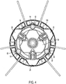
- the head 10 generally includes a body 14 rotatable about an axis of rotation A and defining an axial opening 18 for connection to the trimmer drive shaft.
- the body 14 defines an annular channel 22 for receiving a selected attachment 100.
- the head 10 includes a retainer assembly cooperating with the body 14 to selectively retain the attachment 100.
- the retainer assembly includes a number (e.g., three shown) of retainers 26 adjustable between a retaining position ( Figs. 3-4 and 6 ), in which the retainers 26 cover or block the channel 22 to retain the selected attachment 100, and a release position (not shown), in which the retainers 26 uncover or unblock the channel 22 to allow the attachment 100 to move relative to the channel 22 (e.g., to be removed or installed).
- the retainers 26 have substantially the same shape (e.g., trapezoidal) and are spaced substantially equidistant about the axis A (e.g., spaced about 120° apart).
- An actuating mechanism (see Figs. 1 and 6 ; e.g., including a strike plate 30 and a retainer carrier 34) is operable by a user (e.g., by engaging the strike plate 30, a lever (not shown), a guard (not shown), etc.) to adjust the position of the retainers 26.
- a biasing member biases the retainers 26 to the retaining position; for example, in the illustrated construction (see Fig. 6 ), a spring 38 biases the actuating mechanism to a position corresponding to the retaining position of the retainers 26.
- the retainers 26 are radially movable between the retaining and the release positions, and the actuating mechanism is axially movable to adjust the position of the retainers 26.
- the retainers 26 and/or the actuating mechanism may be movable in another manner (e.g., circumferentially, axially, radially, combinations thereof, etc.) between the positions.
- retainers 26 may be provided. Also, each or all of the retainers 26 may have a different shape than illustrated. In addition, the retainers 26 may have a different spacing (e.g., equidistant based on the number of retainers 26, non-equidistant, etc.).
- body 14 includes (see Figs. 2 and 5 ) a number (e.g., three shown) of radial projections 42 drivingly engageable with a supported attachment 100.
- the illustrated projections 42 have substantially the same shape (e.g., trapezoidal) and are spaced substantially equidistant about the axis A (e.g., spaced about 120° apart).
- the retainers 26 are positioned circumferentially in alignment with and overlying an associated projection 42 of the body 14.
- the body 14 may include fewer or more than three projections 42.
- each or all of the projections 42 may have a different shape than illustrated.
- the projections 42 may have a different spacing (e.g., equidistant based on the number of projections 42 on the body 14, non-equidistant, etc.).
- the projections 42 may extend in and/or engage the attachment 100 in a different manner (e.g., axially, circumferentially, combinations thereof, etc.).
- the head 10 also includes (see Figs. 1 and 3 ) a lower housing 46 connectable to the body 14, for example, with fasteners 50, to house and/or retain components of the head 10 as a unit.
- the lower housing 46 covers the lower portion of the components of the head 10 to inhibit cut material, debris, etc. from interfering with operation of the components.
- the lower housing 46 is sized to allow installation and removal of the attachment 100.
- the body 14 includes (see Figs. 2 and 4-5 ) an associated boss 54 for each fastener 50, and each illustrated boss 54 projects radially into the channel 22.
- Figs. 7-13 illustrate an attachment 100, such as, in the illustrated example, a blower attachment.
- the attachment 100 may include, for example, a cutter (not shown), a string trimmer (see Figs. 2-6 ), an edger (not shown), etc.
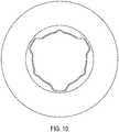
- the attachment 100 includes a body 104 defining a central opening 108 to engage the body 14 of the head 10 (e.g., in the channel 22).
- the attachment 100 defines a number (e.g., three shown) of notches 112 and a number (e.g., three shown) of recesses 116 around the perimeter of the opening 108.
- the notches 112 are complementary to and drivingly engageable with the projections 42 on the body 14 to cooperate to provide the drive arrangement.
- the illustrated notches 112 are shaped (e.g., trapezoidal) and positioned (e.g., equidistant; about 120° apart) to receive the projections 42.
- the recesses 116 are shaped and positioned to receive the bosses 54.
- the attachment 100 is supportable on the body 14 in any position in which the projections 42 engage the notches 112.
- attachment 100 may include fewer or more than three notches 112. Also, each or all of the notches 112 may have a different shape than illustrated. In addition, the notches 112 may have a different spacing (e.g., equidistant based on the number of notches 112, non-equidistant, etc.). In constructions in which the interface between the body 14 and the attachment 100 is non-uniform (e.g., the projections 42 and corresponding notches 112 have a different shape and/positioning), the attachment 100 may be installed in a limited number of rotational positions relative to the body 14. In other constructions (not shown), the projections 42 and notches 112 may be reversed and positioned on the other of the body 14 and the attachment 100.
- the body 104 includes an inner rim 120, which engages the radial wall of the channel 22 of the body 14, an outer rim 124, and an annular plate 126 extending therebetween.
- the operating portion of the attachment 100 extends from the body 104.
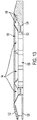
- the blower attachment 100 includes annular first and second plates 128, 132.
- the outer diameters of the plates 128, 132 are substantially equal.
- the first plate 128 extends inwardly to the lower end of the outer rim 124.
- the second plate 132 is narrower than the first plate 128 to define an annular opening 136.
- the blower attachment 100 is positioned on the head 10 with the annular opening 136 oriented upwardly, away from the ground.
- the inner diameter of the second plate 132 is spaced radially outwardly from the body 14 of the head 10, which creates a gap (not shown) between the body 14 and the second plate 132.
- the blower attachment 100 may include structure (not shown) to ensure that the blower attachment 100 is supported in this orientation on the head 10.
- the structure may include an interfering surface in the opening 108 (e.g., in a notch 112) which inhibits installation of the blower attachment 100 in the inverted orientation without interfering with operation of the associated retainer 26 or the radial drive projection 42.
- the structure may include an indication to the user of the proper orientation (e.g., "This side up.”).
- the plates 128, 132 are spaced apart along the axis A, and the second plate 132 is inclined with respect to the first plate 128 from the outer diameter toward the axis A.
- the illustrated second plate 132 is closer to the first plate 128 proximate the outer diameters of the plates 128, 132 and is spaced further from the first plate 128 proximate the inner diameter of the second plate 132.
- the second plate 132 is inclined such that the distance between the plates 128, 132 increases in a direction towards the inner diameter of the second plate 132 and the axis A.
- a plurality of fins 140 is positioned between the plates 128, 132.
- each fin 140 extends from and is substantially orthogonal to the first plate 128.
- Each illustrated fin 140 has a length equal to the distance between the inner diameter and the outer diameter of the first plate 128.
- a radially outer, upper end of each fin 140 is inclined to match the surface of the second plate 132.
- a radially inner, upper end of each fin 140 is exposed and is inclined in the opposite direction. In other words, a height of the exposed portion of the fins 140, with respect to the first plate 128, decreases from the inner diameter of the second plate 132 to the inner diameter of the first plate 128 (to a height below the upper end of the outer rim 124).
- the fins 140 are spaced apart around the circumference of the plates 128, 132. In the illustrated embodiment, the fins 140 are spaced substantially equidistant about the axis A. Adjacent fins 140 define a channel 144 therebetween in the opening 136 and between the plates 128, 132. Due to the inclination of the second plate 132, each channel 144 is axially taller at the opening 136, and the height of each channel 144 decreases toward the outer diameters of the plates 128, 132.
- the actuating mechanism is operated (e.g., the strike plate 30 is depressed to move the carrier 34 downwardly) to adjust the retainers 26 to the release position, opening the channel 22.
- the blower attachment 100 is installed on the body 14 into the channel 22 with each drive projection 42 being received in an associated notch 112 and each boss 54 being received in an associated recess 116.
- the actuating mechanism is operated (e.g., the strike plate 30 is released, and the spring 38 moves the carrier 34 upwardly) to adjust the retainers 26 to the retaining position, covering the channel (see Fig. 6 ).
- blower attachment 100 To remove the blower attachment 100, the process is reversed.
- the actuating mechanism is operated to move the retainers 26 to the release position, uncovering the channel 22.
- the blower attachment 100 may then be removed from the channel 22 and from the head 10. If the trimmer is held in the operating orientation, the blower attachment 100 will fall off of the head 10.
- the user may invert the trimmer so that the head 10 faces upwardly and place the attachment 100 on the head 10.
- the actuating mechanism is operated to move the retainers 26 to the retaining position, covering the channel 22 and retaining the attachment 100. Due to the simplicity of changing the attachment 100, a user may interchange attachments 100 very quickly (e.g., within seconds), with different attachments 100 being used for different operations (e.g., cutting, trimming, edging, blowing, etc.).
- blower attachment 100 With the blower attachment 100 supported on the head 10, operation of the trimmer causes rotation of the head 10 and the driven attachment 100.
- the rotating blower attachment 100 draws air into the opening 136 and expels air radially outwardly through the channels 144 at an increased velocity.
- the generated air flow from the blower attachment 100 may blow debris (e.g., grass trimmings, leaves, etc.) from a work surface (e.g., a sidewalk, driveway, etc.).
- a work surface e.g., a sidewalk, driveway, etc.
Landscapes
- Engineering & Computer Science (AREA)
- Mechanical Engineering (AREA)
- General Engineering & Computer Science (AREA)
- Life Sciences & Earth Sciences (AREA)
- Environmental Sciences (AREA)
- Structures Of Non-Positive Displacement Pumps (AREA)
- Harvester Elements (AREA)
Applications Claiming Priority (1)
| Application Number | Priority Date | Filing Date | Title |
|---|---|---|---|
| US201862640816P | 2018-03-09 | 2018-03-09 |
Publications (2)
| Publication Number | Publication Date |
|---|---|
| EP3536138A1 true EP3536138A1 (fr) | 2019-09-11 |
| EP3536138B1 EP3536138B1 (fr) | 2021-06-02 |
Family
ID=65763279
Family Applications (1)
| Application Number | Title | Priority Date | Filing Date |
|---|---|---|---|
| EP19161724.0A Active EP3536138B1 (fr) | 2018-03-09 | 2019-03-08 | Fixation de ventilateur pour une tête de tondeuse |
Country Status (2)
| Country | Link |
|---|---|
| EP (1) | EP3536138B1 (fr) |
| CN (1) | CN110235594B (fr) |
Cited By (1)
| Publication number | Priority date | Publication date | Assignee | Title |
|---|---|---|---|---|
| EP3677109A1 (fr) * | 2019-01-03 | 2020-07-08 | Techtronic Cordless GP | Ensemble de tête de coupe pour tondeuse |
Citations (9)
| Publication number | Priority date | Publication date | Assignee | Title |
|---|---|---|---|---|
| FR2241211A5 (en) * | 1973-08-14 | 1975-03-14 | Neu Ets | Centrifugal blower enclosed rotor - has holes in lines parallel to discharge tip edges of blades |
| US4047299A (en) * | 1976-01-30 | 1977-09-13 | Garden Pro, Inc. | Apparatus for trimming vegetation |
| US4068376A (en) * | 1976-10-26 | 1978-01-17 | Allied Industries Of Kansas, Inc. | Flexible cutting line and rotor therefor |
| US4524515A (en) * | 1976-10-18 | 1985-06-25 | The Toro Company | Rotary cutting assembly with filament feed |
| EP0496084A1 (fr) * | 1991-01-23 | 1992-07-29 | Philipp Hilge GmbH | Rouet pour pompes centrifuges |
| US5657542A (en) * | 1993-12-22 | 1997-08-19 | The Toro Company | Filament trimmer head |
| US6108914A (en) | 1997-07-25 | 2000-08-29 | Ryobi North America, Inc. | Fixed line trimmer head |
| US20060005347A1 (en) * | 2003-02-12 | 2006-01-12 | Mtd Products Inc | Combination string trimmer and blower tool |
| US8464431B2 (en) | 2009-01-22 | 2013-06-18 | Techtronic Outdoor Products Technology Limited | String head for a trimmer |
Family Cites Families (1)
| Publication number | Priority date | Publication date | Assignee | Title |
|---|---|---|---|---|
| CN203584895U (zh) * | 2013-11-25 | 2014-05-07 | 兴化市台林机械有限公司 | 一种大排风量叶轮及使用该叶轮的气垫式草坪割草机 |
-
2019
- 2019-03-08 EP EP19161724.0A patent/EP3536138B1/fr active Active
- 2019-03-08 CN CN201910179345.0A patent/CN110235594B/zh active Active
Patent Citations (9)
| Publication number | Priority date | Publication date | Assignee | Title |
|---|---|---|---|---|
| FR2241211A5 (en) * | 1973-08-14 | 1975-03-14 | Neu Ets | Centrifugal blower enclosed rotor - has holes in lines parallel to discharge tip edges of blades |
| US4047299A (en) * | 1976-01-30 | 1977-09-13 | Garden Pro, Inc. | Apparatus for trimming vegetation |
| US4524515A (en) * | 1976-10-18 | 1985-06-25 | The Toro Company | Rotary cutting assembly with filament feed |
| US4068376A (en) * | 1976-10-26 | 1978-01-17 | Allied Industries Of Kansas, Inc. | Flexible cutting line and rotor therefor |
| EP0496084A1 (fr) * | 1991-01-23 | 1992-07-29 | Philipp Hilge GmbH | Rouet pour pompes centrifuges |
| US5657542A (en) * | 1993-12-22 | 1997-08-19 | The Toro Company | Filament trimmer head |
| US6108914A (en) | 1997-07-25 | 2000-08-29 | Ryobi North America, Inc. | Fixed line trimmer head |
| US20060005347A1 (en) * | 2003-02-12 | 2006-01-12 | Mtd Products Inc | Combination string trimmer and blower tool |
| US8464431B2 (en) | 2009-01-22 | 2013-06-18 | Techtronic Outdoor Products Technology Limited | String head for a trimmer |
Cited By (2)
| Publication number | Priority date | Publication date | Assignee | Title |
|---|---|---|---|---|
| EP3677109A1 (fr) * | 2019-01-03 | 2020-07-08 | Techtronic Cordless GP | Ensemble de tête de coupe pour tondeuse |
| US11503763B2 (en) | 2019-01-03 | 2022-11-22 | Techtronic Cordless Gp | Trimmer head assembly for a trimmer |
Also Published As
| Publication number | Publication date |
|---|---|
| CN110235594A (zh) | 2019-09-17 |
| CN110235594B (zh) | 2022-03-01 |
| EP3536138B1 (fr) | 2021-06-02 |
Similar Documents
| Publication | Publication Date | Title |
|---|---|---|
| EP2210467B1 (fr) | Tête à fil pour tondeuse | |
| US4068376A (en) | Flexible cutting line and rotor therefor | |
| US10299430B2 (en) | String trimmer with adjustable guard assembly | |
| CN222193146U (zh) | 修剪机头及线式修剪机 | |
| US4490910A (en) | Cutting head for string trimmer | |
| CN221996059U (zh) | 修剪机头和线式修剪机 | |
| US11412656B2 (en) | Trimmer head with improved line release feature | |
| EP3729947B1 (fr) | Mécanisme principal de machine de travail | |
| US20110131815A1 (en) | Combination blower and trimmer assembly | |
| EP4154696A1 (fr) | Protection de tondeuse et tondeuse | |
| US7047592B2 (en) | Combination blower assembly and string trimmer | |
| EP3536138A1 (fr) | Fixation de ventilateur pour une tête de tondeuse | |
| US20110277328A1 (en) | String trimmer shield | |
| EP3536140A1 (fr) | Fixation de tondeuse à fil pour une tête de tondeuse | |
| EP3545742B1 (fr) | Tête de tondeuse et accessoires | |
| US20060005347A1 (en) | Combination string trimmer and blower tool | |
| EP3536139B1 (fr) | Fixation de coupe-bordures pour tête de tondeuse | |
| EP4434316A1 (fr) | Lames de coupe-bordure | |
| US20100126023A1 (en) | Combination String Trimmer and Blower Tool | |
| EP3351085B1 (fr) | Protection de tondeuse et tondeuse |
Legal Events
| Date | Code | Title | Description |
|---|---|---|---|
| PUAI | Public reference made under article 153(3) epc to a published international application that has entered the european phase |
Free format text: ORIGINAL CODE: 0009012 |
|
| STAA | Information on the status of an ep patent application or granted ep patent |
Free format text: STATUS: THE APPLICATION HAS BEEN PUBLISHED |
|
| AK | Designated contracting states |
Kind code of ref document: A1 Designated state(s): AL AT BE BG CH CY CZ DE DK EE ES FI FR GB GR HR HU IE IS IT LI LT LU LV MC MK MT NL NO PL PT RO RS SE SI SK SM TR |
|
| AX | Request for extension of the european patent |
Extension state: BA ME |
|
| STAA | Information on the status of an ep patent application or granted ep patent |
Free format text: STATUS: REQUEST FOR EXAMINATION WAS MADE |
|
| 17P | Request for examination filed |
Effective date: 20200115 |
|
| RBV | Designated contracting states (corrected) |
Designated state(s): AL AT BE BG CH CY CZ DE DK EE ES FI FR GB GR HR HU IE IS IT LI LT LU LV MC MK MT NL NO PL PT RO RS SE SI SK SM TR |
|
| STAA | Information on the status of an ep patent application or granted ep patent |
Free format text: STATUS: EXAMINATION IS IN PROGRESS |
|
| 17Q | First examination report despatched |
Effective date: 20200706 |
|
| RAP1 | Party data changed (applicant data changed or rights of an application transferred) |
Owner name: TTI (MACAO COMMERCIAL OFFSHORE) LIMITED |
|
| GRAP | Despatch of communication of intention to grant a patent |
Free format text: ORIGINAL CODE: EPIDOSNIGR1 |
|
| STAA | Information on the status of an ep patent application or granted ep patent |
Free format text: STATUS: GRANT OF PATENT IS INTENDED |
|
| INTG | Intention to grant announced |
Effective date: 20210104 |
|
| INTG | Intention to grant announced |
Effective date: 20210114 |
|
| GRAS | Grant fee paid |
Free format text: ORIGINAL CODE: EPIDOSNIGR3 |
|
| GRAA | (expected) grant |
Free format text: ORIGINAL CODE: 0009210 |
|
| STAA | Information on the status of an ep patent application or granted ep patent |
Free format text: STATUS: THE PATENT HAS BEEN GRANTED |
|
| REG | Reference to a national code |
Ref country code: CH Ref legal event code: EP |
|
| AK | Designated contracting states |
Kind code of ref document: B1 Designated state(s): AL AT BE BG CH CY CZ DE DK EE ES FI FR GB GR HR HU IE IS IT LI LT LU LV MC MK MT NL NO PL PT RO RS SE SI SK SM TR |
|
| REG | Reference to a national code |
Ref country code: GB Ref legal event code: FG4D |
|
| REG | Reference to a national code |
Ref country code: AT Ref legal event code: REF Ref document number: 1397585 Country of ref document: AT Kind code of ref document: T Effective date: 20210615 |
|
| REG | Reference to a national code |
Ref country code: IE Ref legal event code: FG4D |
|
| REG | Reference to a national code |
Ref country code: DE Ref legal event code: R096 Ref document number: 602019004954 Country of ref document: DE |
|
| REG | Reference to a national code |
Ref country code: LT Ref legal event code: MG9D |
|
| PG25 | Lapsed in a contracting state [announced via postgrant information from national office to epo] |
Ref country code: BG Free format text: LAPSE BECAUSE OF FAILURE TO SUBMIT A TRANSLATION OF THE DESCRIPTION OR TO PAY THE FEE WITHIN THE PRESCRIBED TIME-LIMIT Effective date: 20210902 Ref country code: HR Free format text: LAPSE BECAUSE OF FAILURE TO SUBMIT A TRANSLATION OF THE DESCRIPTION OR TO PAY THE FEE WITHIN THE PRESCRIBED TIME-LIMIT Effective date: 20210602 Ref country code: LT Free format text: LAPSE BECAUSE OF FAILURE TO SUBMIT A TRANSLATION OF THE DESCRIPTION OR TO PAY THE FEE WITHIN THE PRESCRIBED TIME-LIMIT Effective date: 20210602 Ref country code: FI Free format text: LAPSE BECAUSE OF FAILURE TO SUBMIT A TRANSLATION OF THE DESCRIPTION OR TO PAY THE FEE WITHIN THE PRESCRIBED TIME-LIMIT Effective date: 20210602 |
|
| REG | Reference to a national code |
Ref country code: NL Ref legal event code: MP Effective date: 20210602 |
|
| REG | Reference to a national code |
Ref country code: AT Ref legal event code: MK05 Ref document number: 1397585 Country of ref document: AT Kind code of ref document: T Effective date: 20210602 |
|
| PG25 | Lapsed in a contracting state [announced via postgrant information from national office to epo] |
Ref country code: GR Free format text: LAPSE BECAUSE OF FAILURE TO SUBMIT A TRANSLATION OF THE DESCRIPTION OR TO PAY THE FEE WITHIN THE PRESCRIBED TIME-LIMIT Effective date: 20210903 Ref country code: PL Free format text: LAPSE BECAUSE OF FAILURE TO SUBMIT A TRANSLATION OF THE DESCRIPTION OR TO PAY THE FEE WITHIN THE PRESCRIBED TIME-LIMIT Effective date: 20210602 Ref country code: LV Free format text: LAPSE BECAUSE OF FAILURE TO SUBMIT A TRANSLATION OF THE DESCRIPTION OR TO PAY THE FEE WITHIN THE PRESCRIBED TIME-LIMIT Effective date: 20210602 Ref country code: NO Free format text: LAPSE BECAUSE OF FAILURE TO SUBMIT A TRANSLATION OF THE DESCRIPTION OR TO PAY THE FEE WITHIN THE PRESCRIBED TIME-LIMIT Effective date: 20210902 Ref country code: RS Free format text: LAPSE BECAUSE OF FAILURE TO SUBMIT A TRANSLATION OF THE DESCRIPTION OR TO PAY THE FEE WITHIN THE PRESCRIBED TIME-LIMIT Effective date: 20210602 Ref country code: SE Free format text: LAPSE BECAUSE OF FAILURE TO SUBMIT A TRANSLATION OF THE DESCRIPTION OR TO PAY THE FEE WITHIN THE PRESCRIBED TIME-LIMIT Effective date: 20210602 |
|
| PG25 | Lapsed in a contracting state [announced via postgrant information from national office to epo] |
Ref country code: SK Free format text: LAPSE BECAUSE OF FAILURE TO SUBMIT A TRANSLATION OF THE DESCRIPTION OR TO PAY THE FEE WITHIN THE PRESCRIBED TIME-LIMIT Effective date: 20210602 Ref country code: ES Free format text: LAPSE BECAUSE OF FAILURE TO SUBMIT A TRANSLATION OF THE DESCRIPTION OR TO PAY THE FEE WITHIN THE PRESCRIBED TIME-LIMIT Effective date: 20210602 Ref country code: EE Free format text: LAPSE BECAUSE OF FAILURE TO SUBMIT A TRANSLATION OF THE DESCRIPTION OR TO PAY THE FEE WITHIN THE PRESCRIBED TIME-LIMIT Effective date: 20210602 Ref country code: PT Free format text: LAPSE BECAUSE OF FAILURE TO SUBMIT A TRANSLATION OF THE DESCRIPTION OR TO PAY THE FEE WITHIN THE PRESCRIBED TIME-LIMIT Effective date: 20211004 Ref country code: NL Free format text: LAPSE BECAUSE OF FAILURE TO SUBMIT A TRANSLATION OF THE DESCRIPTION OR TO PAY THE FEE WITHIN THE PRESCRIBED TIME-LIMIT Effective date: 20210602 Ref country code: RO Free format text: LAPSE BECAUSE OF FAILURE TO SUBMIT A TRANSLATION OF THE DESCRIPTION OR TO PAY THE FEE WITHIN THE PRESCRIBED TIME-LIMIT Effective date: 20210602 Ref country code: SM Free format text: LAPSE BECAUSE OF FAILURE TO SUBMIT A TRANSLATION OF THE DESCRIPTION OR TO PAY THE FEE WITHIN THE PRESCRIBED TIME-LIMIT Effective date: 20210602 Ref country code: AT Free format text: LAPSE BECAUSE OF FAILURE TO SUBMIT A TRANSLATION OF THE DESCRIPTION OR TO PAY THE FEE WITHIN THE PRESCRIBED TIME-LIMIT Effective date: 20210602 Ref country code: CZ Free format text: LAPSE BECAUSE OF FAILURE TO SUBMIT A TRANSLATION OF THE DESCRIPTION OR TO PAY THE FEE WITHIN THE PRESCRIBED TIME-LIMIT Effective date: 20210602 |
|
| REG | Reference to a national code |
Ref country code: DE Ref legal event code: R097 Ref document number: 602019004954 Country of ref document: DE |
|
| PLBE | No opposition filed within time limit |
Free format text: ORIGINAL CODE: 0009261 |
|
| STAA | Information on the status of an ep patent application or granted ep patent |
Free format text: STATUS: NO OPPOSITION FILED WITHIN TIME LIMIT |
|
| PG25 | Lapsed in a contracting state [announced via postgrant information from national office to epo] |
Ref country code: DK Free format text: LAPSE BECAUSE OF FAILURE TO SUBMIT A TRANSLATION OF THE DESCRIPTION OR TO PAY THE FEE WITHIN THE PRESCRIBED TIME-LIMIT Effective date: 20210602 |
|
| 26N | No opposition filed |
Effective date: 20220303 |
|
| PG25 | Lapsed in a contracting state [announced via postgrant information from national office to epo] |
Ref country code: AL Free format text: LAPSE BECAUSE OF FAILURE TO SUBMIT A TRANSLATION OF THE DESCRIPTION OR TO PAY THE FEE WITHIN THE PRESCRIBED TIME-LIMIT Effective date: 20210602 |
|
| PG25 | Lapsed in a contracting state [announced via postgrant information from national office to epo] |
Ref country code: IT Free format text: LAPSE BECAUSE OF FAILURE TO SUBMIT A TRANSLATION OF THE DESCRIPTION OR TO PAY THE FEE WITHIN THE PRESCRIBED TIME-LIMIT Effective date: 20210602 |
|
| PG25 | Lapsed in a contracting state [announced via postgrant information from national office to epo] |
Ref country code: MC Free format text: LAPSE BECAUSE OF FAILURE TO SUBMIT A TRANSLATION OF THE DESCRIPTION OR TO PAY THE FEE WITHIN THE PRESCRIBED TIME-LIMIT Effective date: 20210602 |
|
| REG | Reference to a national code |
Ref country code: CH Ref legal event code: PL |
|
| REG | Reference to a national code |
Ref country code: BE Ref legal event code: MM Effective date: 20220331 |
|
| PG25 | Lapsed in a contracting state [announced via postgrant information from national office to epo] |
Ref country code: LU Free format text: LAPSE BECAUSE OF NON-PAYMENT OF DUE FEES Effective date: 20220308 Ref country code: LI Free format text: LAPSE BECAUSE OF NON-PAYMENT OF DUE FEES Effective date: 20220331 Ref country code: IE Free format text: LAPSE BECAUSE OF NON-PAYMENT OF DUE FEES Effective date: 20220308 Ref country code: CH Free format text: LAPSE BECAUSE OF NON-PAYMENT OF DUE FEES Effective date: 20220331 |
|
| PG25 | Lapsed in a contracting state [announced via postgrant information from national office to epo] |
Ref country code: BE Free format text: LAPSE BECAUSE OF NON-PAYMENT OF DUE FEES Effective date: 20220331 |
|
| PG25 | Lapsed in a contracting state [announced via postgrant information from national office to epo] |
Ref country code: MK Free format text: LAPSE BECAUSE OF FAILURE TO SUBMIT A TRANSLATION OF THE DESCRIPTION OR TO PAY THE FEE WITHIN THE PRESCRIBED TIME-LIMIT Effective date: 20210602 Ref country code: CY Free format text: LAPSE BECAUSE OF FAILURE TO SUBMIT A TRANSLATION OF THE DESCRIPTION OR TO PAY THE FEE WITHIN THE PRESCRIBED TIME-LIMIT Effective date: 20210602 |
|
| PG25 | Lapsed in a contracting state [announced via postgrant information from national office to epo] |
Ref country code: HU Free format text: LAPSE BECAUSE OF FAILURE TO SUBMIT A TRANSLATION OF THE DESCRIPTION OR TO PAY THE FEE WITHIN THE PRESCRIBED TIME-LIMIT; INVALID AB INITIO Effective date: 20190308 |
|
| PG25 | Lapsed in a contracting state [announced via postgrant information from national office to epo] |
Ref country code: TR Free format text: LAPSE BECAUSE OF FAILURE TO SUBMIT A TRANSLATION OF THE DESCRIPTION OR TO PAY THE FEE WITHIN THE PRESCRIBED TIME-LIMIT Effective date: 20210602 |
|
| PG25 | Lapsed in a contracting state [announced via postgrant information from national office to epo] |
Ref country code: MT Free format text: LAPSE BECAUSE OF FAILURE TO SUBMIT A TRANSLATION OF THE DESCRIPTION OR TO PAY THE FEE WITHIN THE PRESCRIBED TIME-LIMIT Effective date: 20210602 |
|
| PGFP | Annual fee paid to national office [announced via postgrant information from national office to epo] |
Ref country code: GB Payment date: 20260327 Year of fee payment: 8 |
|
| PGFP | Annual fee paid to national office [announced via postgrant information from national office to epo] |
Ref country code: DE Payment date: 20260327 Year of fee payment: 8 |
|
| PGFP | Annual fee paid to national office [announced via postgrant information from national office to epo] |
Ref country code: FR Payment date: 20260325 Year of fee payment: 8 |