EP3536156A1 - Verfahren und vorrichtung zum auftragen von massen auf lebensmittel - Google Patents
Verfahren und vorrichtung zum auftragen von massen auf lebensmittel Download PDFInfo
- Publication number
- EP3536156A1 EP3536156A1 EP19160980.9A EP19160980A EP3536156A1 EP 3536156 A1 EP3536156 A1 EP 3536156A1 EP 19160980 A EP19160980 A EP 19160980A EP 3536156 A1 EP3536156 A1 EP 3536156A1
- Authority
- EP
- European Patent Office
- Prior art keywords
- flow channel
- mass
- supply line
- compressed gas
- opening
- Prior art date
- Legal status (The legal status is an assumption and is not a legal conclusion. Google has not performed a legal analysis and makes no representation as to the accuracy of the status listed.)
- Granted
Links
Images


Classifications
-
- B—PERFORMING OPERATIONS; TRANSPORTING
- B05—SPRAYING OR ATOMISING IN GENERAL; APPLYING FLUENT MATERIALS TO SURFACES, IN GENERAL
- B05B—SPRAYING APPARATUS; ATOMISING APPARATUS; NOZZLES
- B05B13/00—Machines or plants for applying liquids or other fluent materials to surfaces of objects or other work by spraying, not covered by groups B05B1/00 - B05B11/00
- B05B13/02—Means for supporting work; Arrangement or mounting of spray heads; Adaptation or arrangement of means for feeding work
- B05B13/0278—Arrangement or mounting of spray heads
-
- B—PERFORMING OPERATIONS; TRANSPORTING
- B05—SPRAYING OR ATOMISING IN GENERAL; APPLYING FLUENT MATERIALS TO SURFACES, IN GENERAL
- B05B—SPRAYING APPARATUS; ATOMISING APPARATUS; NOZZLES
- B05B7/00—Spraying apparatus for discharge of liquids or other fluent materials from two or more sources, e.g. of liquid and air, of powder and gas
- B05B7/0081—Apparatus supplied with low pressure gas, e.g. "hvlp"-guns; air supplied by a fan
- B05B7/0087—Atmospheric air being sucked by a gas stream, generally flowing through a venturi, at a location upstream or inside the spraying apparatus
-
- A—HUMAN NECESSITIES
- A23—FOODS OR FOODSTUFFS; TREATMENT THEREOF, NOT COVERED BY OTHER CLASSES
- A23B—PRESERVATION OF FOODS, FOODSTUFFS OR NON-ALCOHOLIC BEVERAGES; CHEMICAL RIPENING OF FRUIT OR VEGETABLES
- A23B4/00—Preservation of meat, sausages, fish or fish products
- A23B4/26—Apparatus for preserving using liquids ; Processes therefor
- A23B4/30—Apparatus for preserving using liquids ; Processes therefor by spraying of liquids
-
- A—HUMAN NECESSITIES
- A23—FOODS OR FOODSTUFFS; TREATMENT THEREOF, NOT COVERED BY OTHER CLASSES
- A23P—SHAPING OR WORKING OF FOODSTUFFS, NOT FULLY COVERED BY A SINGLE OTHER SUBCLASS
- A23P20/00—Coating of foodstuffs; Coatings therefor; Making laminated, multi-layered, stuffed or hollow foodstuffs
- A23P20/10—Coating with edible coatings, e.g. with oils or fats
- A23P20/12—Apparatus or processes for applying powders or particles to foodstuffs, e.g. for breading; Such apparatus combined with means for pre-moistening or battering
-
- A—HUMAN NECESSITIES
- A23—FOODS OR FOODSTUFFS; TREATMENT THEREOF, NOT COVERED BY OTHER CLASSES
- A23P—SHAPING OR WORKING OF FOODSTUFFS, NOT FULLY COVERED BY A SINGLE OTHER SUBCLASS
- A23P20/00—Coating of foodstuffs; Coatings therefor; Making laminated, multi-layered, stuffed or hollow foodstuffs
- A23P20/10—Coating with edible coatings, e.g. with oils or fats
- A23P20/15—Apparatus or processes for coating with liquid or semi-liquid products
- A23P20/18—Apparatus or processes for coating with liquid or semi-liquid products by spray-coating, fluidised-bed coating or coating by casting
-
- B—PERFORMING OPERATIONS; TRANSPORTING
- B05—SPRAYING OR ATOMISING IN GENERAL; APPLYING FLUENT MATERIALS TO SURFACES, IN GENERAL
- B05B—SPRAYING APPARATUS; ATOMISING APPARATUS; NOZZLES
- B05B12/00—Arrangements for controlling delivery; Arrangements for controlling the spray area
- B05B12/004—Arrangements for controlling delivery; Arrangements for controlling the spray area comprising sensors for monitoring the delivery, e.g. by displaying the sensed value or generating an alarm
-
- B—PERFORMING OPERATIONS; TRANSPORTING
- B05—SPRAYING OR ATOMISING IN GENERAL; APPLYING FLUENT MATERIALS TO SURFACES, IN GENERAL
- B05B—SPRAYING APPARATUS; ATOMISING APPARATUS; NOZZLES
- B05B13/00—Machines or plants for applying liquids or other fluent materials to surfaces of objects or other work by spraying, not covered by groups B05B1/00 - B05B11/00
- B05B13/02—Means for supporting work; Arrangement or mounting of spray heads; Adaptation or arrangement of means for feeding work
- B05B13/0221—Means for supporting work; Arrangement or mounting of spray heads; Adaptation or arrangement of means for feeding work characterised by the means for moving or conveying the objects or other work, e.g. conveyor belts
-
- B—PERFORMING OPERATIONS; TRANSPORTING
- B05—SPRAYING OR ATOMISING IN GENERAL; APPLYING FLUENT MATERIALS TO SURFACES, IN GENERAL
- B05B—SPRAYING APPARATUS; ATOMISING APPARATUS; NOZZLES
- B05B7/00—Spraying apparatus for discharge of liquids or other fluent materials from two or more sources, e.g. of liquid and air, of powder and gas
- B05B7/02—Spray pistols; Apparatus for discharge
- B05B7/04—Spray pistols; Apparatus for discharge with arrangements for mixing liquids or other fluent materials before discharge
- B05B7/0416—Spray pistols; Apparatus for discharge with arrangements for mixing liquids or other fluent materials before discharge with arrangements for mixing one gas and one liquid
- B05B7/0483—Spray pistols; Apparatus for discharge with arrangements for mixing liquids or other fluent materials before discharge with arrangements for mixing one gas and one liquid with gas and liquid jets intersecting in the mixing chamber
-
- B—PERFORMING OPERATIONS; TRANSPORTING
- B05—SPRAYING OR ATOMISING IN GENERAL; APPLYING FLUENT MATERIALS TO SURFACES, IN GENERAL
- B05B—SPRAYING APPARATUS; ATOMISING APPARATUS; NOZZLES
- B05B7/00—Spraying apparatus for discharge of liquids or other fluent materials from two or more sources, e.g. of liquid and air, of powder and gas
- B05B7/24—Spraying apparatus for discharge of liquids or other fluent materials from two or more sources, e.g. of liquid and air, of powder and gas with means, e.g. a container, for supplying liquid or other fluent material to a discharge device
- B05B7/2402—Apparatus to be carried on or by a person, e.g. by hand; Apparatus comprising containers fixed to the discharge device
- B05B7/2405—Apparatus to be carried on or by a person, e.g. by hand; Apparatus comprising containers fixed to the discharge device using an atomising fluid as carrying fluid for feeding, e.g. by suction or pressure, a carried liquid from the container to the nozzle
- B05B7/2435—Apparatus to be carried on or by a person, e.g. by hand; Apparatus comprising containers fixed to the discharge device using an atomising fluid as carrying fluid for feeding, e.g. by suction or pressure, a carried liquid from the container to the nozzle the carried liquid and the main stream of atomising fluid being brought together by parallel conduits placed one inside the other
-
- B—PERFORMING OPERATIONS; TRANSPORTING
- B05—SPRAYING OR ATOMISING IN GENERAL; APPLYING FLUENT MATERIALS TO SURFACES, IN GENERAL
- B05B—SPRAYING APPARATUS; ATOMISING APPARATUS; NOZZLES
- B05B12/00—Arrangements for controlling delivery; Arrangements for controlling the spray area
- B05B12/08—Arrangements for controlling delivery; Arrangements for controlling the spray area responsive to condition of liquid or other fluent material to be discharged, of ambient medium or of target ; responsive to condition of spray devices or of supply means, e.g. pipes, pumps or their drive means
- B05B12/12—Arrangements for controlling delivery; Arrangements for controlling the spray area responsive to condition of liquid or other fluent material to be discharged, of ambient medium or of target ; responsive to condition of spray devices or of supply means, e.g. pipes, pumps or their drive means responsive to conditions of ambient medium or target, e.g. humidity, temperature position or movement of the target relative to the spray apparatus
- B05B12/122—Arrangements for controlling delivery; Arrangements for controlling the spray area responsive to condition of liquid or other fluent material to be discharged, of ambient medium or of target ; responsive to condition of spray devices or of supply means, e.g. pipes, pumps or their drive means responsive to conditions of ambient medium or target, e.g. humidity, temperature position or movement of the target relative to the spray apparatus responsive to presence or shape of target
-
- B—PERFORMING OPERATIONS; TRANSPORTING
- B05—SPRAYING OR ATOMISING IN GENERAL; APPLYING FLUENT MATERIALS TO SURFACES, IN GENERAL
- B05B—SPRAYING APPARATUS; ATOMISING APPARATUS; NOZZLES
- B05B13/00—Machines or plants for applying liquids or other fluent materials to surfaces of objects or other work by spraying, not covered by groups B05B1/00 - B05B11/00
- B05B13/02—Means for supporting work; Arrangement or mounting of spray heads; Adaptation or arrangement of means for feeding work
- B05B13/0221—Means for supporting work; Arrangement or mounting of spray heads; Adaptation or arrangement of means for feeding work characterised by the means for moving or conveying the objects or other work, e.g. conveyor belts
- B05B13/0264—Overhead conveying means, i.e. the object or other work being suspended from the conveying means; Details thereof, e.g. hanging hooks
-
- B—PERFORMING OPERATIONS; TRANSPORTING
- B05—SPRAYING OR ATOMISING IN GENERAL; APPLYING FLUENT MATERIALS TO SURFACES, IN GENERAL
- B05B—SPRAYING APPARATUS; ATOMISING APPARATUS; NOZZLES
- B05B7/00—Spraying apparatus for discharge of liquids or other fluent materials from two or more sources, e.g. of liquid and air, of powder and gas
- B05B7/02—Spray pistols; Apparatus for discharge
- B05B7/08—Spray pistols; Apparatus for discharge with separate outlet orifices, e.g. to form parallel jets, i.e. the axis of the jets being parallel, to form intersecting jets, i.e. the axis of the jets converging but not necessarily intersecting at a point
- B05B7/0807—Spray pistols; Apparatus for discharge with separate outlet orifices, e.g. to form parallel jets, i.e. the axis of the jets being parallel, to form intersecting jets, i.e. the axis of the jets converging but not necessarily intersecting at a point to form intersecting jets
- B05B7/0815—Spray pistols; Apparatus for discharge with separate outlet orifices, e.g. to form parallel jets, i.e. the axis of the jets being parallel, to form intersecting jets, i.e. the axis of the jets converging but not necessarily intersecting at a point to form intersecting jets with at least one gas jet intersecting a jet constituted by a liquid or a mixture containing a liquid for controlling the shape of the latter
-
- B—PERFORMING OPERATIONS; TRANSPORTING
- B05—SPRAYING OR ATOMISING IN GENERAL; APPLYING FLUENT MATERIALS TO SURFACES, IN GENERAL
- B05B—SPRAYING APPARATUS; ATOMISING APPARATUS; NOZZLES
- B05B7/00—Spraying apparatus for discharge of liquids or other fluent materials from two or more sources, e.g. of liquid and air, of powder and gas
- B05B7/14—Spraying apparatus for discharge of liquids or other fluent materials from two or more sources, e.g. of liquid and air, of powder and gas designed for spraying particulate materials
- B05B7/1481—Spray pistols or apparatus for discharging particulate material
- B05B7/1486—Spray pistols or apparatus for discharging particulate material for spraying particulate material in dry state
-
- B—PERFORMING OPERATIONS; TRANSPORTING
- B05—SPRAYING OR ATOMISING IN GENERAL; APPLYING FLUENT MATERIALS TO SURFACES, IN GENERAL
- B05B—SPRAYING APPARATUS; ATOMISING APPARATUS; NOZZLES
- B05B7/00—Spraying apparatus for discharge of liquids or other fluent materials from two or more sources, e.g. of liquid and air, of powder and gas
- B05B7/24—Spraying apparatus for discharge of liquids or other fluent materials from two or more sources, e.g. of liquid and air, of powder and gas with means, e.g. a container, for supplying liquid or other fluent material to a discharge device
- B05B7/2489—Spraying apparatus for discharge of liquids or other fluent materials from two or more sources, e.g. of liquid and air, of powder and gas with means, e.g. a container, for supplying liquid or other fluent material to a discharge device an atomising fluid, e.g. a gas, being supplied to the discharge device
- B05B7/2494—Spraying apparatus for discharge of liquids or other fluent materials from two or more sources, e.g. of liquid and air, of powder and gas with means, e.g. a container, for supplying liquid or other fluent material to a discharge device an atomising fluid, e.g. a gas, being supplied to the discharge device a liquid being supplied from a pressurized or compressible container to the discharge device
Definitions
- the present invention relates to an apparatus and a method for applying masses, which are powdery, preferably liquid with pieces distributed therein, to food.
- the liquid masses may be aqueous or oily or an emulsion.
- the liquid masses may have a consistency which is as thin as water up to mushy at the temperature at which the process is carried out.
- the compositions preferably contain pieces contained therein, eg of a size of 0.5 mm or from 2 mm to 10 mm, more preferably to 5 or to 3 mm in the largest dimension.
- the pieces may be, for example, spices, eg herbs, whole peppercorns, coarsely ground pepper, pieces of vegetables, pieces of meat or solid fat, vegetable or animal, at 5 to 30 ° C.
- the apparatus and method may be arranged to apply, sequentially or simultaneously, at least two different masses separately, each on the same or opposite sides of the food to produce a mass-coated food.
- the WO00 / 32051 describes the spraying of poultry parts with liquid or powdered additives by means of a gas jet with nozzles not described in detail, also with electrostatic charge of 10 - 40 kV.
- the US 3,436,230 describes nozzles with which liquid can be injected into meat at high pressure without piercing, so that its surface is not damaged, eg at speeds of approx. 180 m / s.
- the object of the invention is to provide an alternative device and a method that can be carried out for applying masses to foods, which are particularly suitable for non-contact application of liquid compositions containing pieces, in particular by means of a gas flow.
- the invention solves the problem with the features of the claims and in particular provides a device for use as a coating device for masses on food and thus a feasible process for the production of coated food by applying a mass to food, with a flow channel at the inlet end of a supply line is arranged for the mass whose mouth is fixed in a region which extends from a distance in front of the inlet end into the flow channel.
- the device comprises a flow channel provided with at least one pressurized gas port and a supply line which, preferably coaxially with the flow channel, terminates in a region in which Flow channel generates negative pressure, which extends from a distance in front of the inlet opening to within the flow channel, or consists thereof.
- the feed line project with its opposite open end into a container for the mass and preferably have no conveyor.
- the device can be arranged below a transport device, for example, with the longitudinal axis of the flow channel vertically and the outlet opening above.
- the supply line is fixed and the arrangement of its mouth in a region in which the flow channel generates vacuum, allows the automatic suction of the mass.
- the supply line may be arranged at a distance from the longitudinal central axis of the flow channel or coaxially with the flow channel.
- the supply line may be arranged at an angle or parallel to the longitudinal center axis of the flow channel.
- the mouth of the supply line is arranged coaxially to the flow channel.
- the container for the mass may be an open-topped container, which is arranged below the transport device, optionally so that from the direction of the transport device down falling mass falls into the container.
- the supply line is displaceably and / or pivotally guided and fixable in a position such that its mouth can be arranged in a region which extends from a distance in front of the inlet end into the flow channel.
- the mouth of the supply line is arranged coaxially to the longitudinal center axis of the flow channel.
- the supply line is optionally connected to a reservoir for a mass, optionally connected to at least two reservoirs each having a supply line and a valve which can switch between the reservoirs and connect a reservoir to the supply line.
- Each reservoir may be connected by a conduit to the supply line, which opens into region which extends from a distance in front of the inlet opening of the flow channel to within the flow channel.
- a controlled conveyor for conveying the mass to the mouth of the supply line.
- the conveyor is eg a pump or displacement pump, preferably a piston or eccentric screw pump, peristaltic pump or centrifugal, screw, diaphragm, impeller, rotary piston, rotary valve, rotary piston or gear pump.
- a reservoir can be pressurized, eg by pressurizing the reservoir with compressed gas, eg compressed air by means of a compressed air connection, preferably by constant pressure, or by forming a container wall, eg the lid, as a piston loaded against the internal volume of the reservoir ,
- a controllable valve is preferably arranged in the supply line.
- Such a valve in the supply line may be controlled as a function of the position of a transport device at which food is transported past the outlet opening of the flow channel past the food, or depending on the signal of a detector for the presence of a food arranged on the transport device in front of the outlet opening of the flow channel.
- a detector may be a photocell, preferably a camera.
- the conveyor is e.g. a screw conveyor, a chute or a blower.
- the feed line for the mass no conveyor is arranged and optionally causes or supports the flow channel alone the promotion of the mass to the mouth of the supply, in particular by the negative pressure generated by the flow channel, which acts on the mouth of the supply.
- the negative pressure generated by the flow channel which acts on the mouth of the supply, cause or support the promotion of the mass through the supply line.
- a storage container preferably all storage containers, arranged for mass above the mouth of the supply line, so that the mass is conveyed by gravity to the mouth.
- a controlled valve is preferably arranged in the supply line.
- the supply line has no valve.
- the conveyor or the supply line is provided with a flow meter.
- the supply line is optionally displaceably guided relative to the flow channel and fixable in a position, preferably arranged coaxially to the longitudinal central axis of the flow channel and guided displaceably along this longitudinal central axis, in particular relative to the inlet end of the flow channel.
- the supply line is arranged at an angle to the longitudinal central axis of the flow channel and fixed or pivotable at an angle to the longitudinal central axis of the flow channel and fixed in a position.
- the supply line is arranged and fixed parallel or at an angle to the longitudinal central axis of the flow channel and / or the supply line is pivotable at an angle to the longitudinal central axis of the flow channel, in one or in two dimensions, which are perpendicular to the longitudinal central axis, displaceably and / or pivotally guided and preferably fixed in one position.
- a feed line displaceable to the longitudinal center axis e.g. by means of one or two linear guides, which along one or two axes perpendicular to the longitudinal central axis of the flow channel form a guide for the supply line, by means of which the supply line is displaceably guided, allows the controlled in different positions eccentric supply of the mass in the flow channel.
- the device is arranged to vary the distribution of the mass controlled, e.g. to influence the distribution of lumpy ingredients controlled.
- the supply line may e.g. be guided displaceable relative to the flow channel by means of at least one adjusting screw or at least one linear drive.
- the supply line may be fixed with its mouth in a position which is described with reference to the embodiment in which the supply line is displaceable and / or pivotable preferably in a position can be fixed.
- the supply line may be slidable over a range relative to the flow channel or within a range extending from a position where the mouth of the supply line is spaced from the plane of the inlet port and from the inlet end outside the flow channel, respectively extends a position in which the mouth of the supply line is disposed within the flow channel, for example, to a position in which the mouth extends into the portion of the flow channel with the smallest inner diameter or beyond in the flow channel.
- the supply line may be slidable so that its mouth is located in a region extending from a distance from the plane of the inlet opening outside the flow channel over the plane of the inlet opening eg to the section of the flow channel with the smallest inside diameter, or eg in a region extending from the plane of the inlet port to the pressurized gas supply port located on or in the flow channel, or in a region extending from the pressurized gas supply port to the discharge port of the flow passage.
- the feed line can be displaceable such that its mouth can be positioned in a region extending from a distance in front of the inlet opening to to the feed opening for compressed gas in the Flow channel extends, or can be positioned in a region which extends from the supply port for compressed gas to the outlet opening.
- the position of the mouth of the feed line relative to the flow channel may be dependent on e.g. be controlled by the pressure and / or by the speed and / or the mass flow of the mass emerging from the feed line or the delivery rate of a conveyor, which may be the pressure applied to the reservoir, or depending on the flow rate of one in the feed line arranged pump and / or depending on the position of a valve disposed in the supply line.
- the flow channel has at least one connected compressed gas line, which is controlled by a valve and opens on the flow channel in at least one supply port for compressed gas, which is adapted to accelerate an air flow in the flow channel from the inlet end to the opposite outlet end.
- the valve is controlled depending on the signal from a food position detector on the food transport.
- the supply of pressurized gas to the supply port is controlled, e.g. the supply of pressurized gas is opened depending on a signal of a detector for the presence of a arranged on the transport means food before the outlet opening of the flow channel, so that controlled only in detection of a food before the outlet pressure gas is fed into the flow channel.
- the supply of compressed gas is controlled as a function of a signal of a flow meter.
- the pressurized gas may be supplied to the at least one feed port at a pressure of 0.1 to 15 bar, e.g. 0.1 to 10 bar are supplied.
- the pressurized gas may be supplied intermittently, e.g.
- the device may be configured to open a valve in the compressed gas line controlled intermittently.
- the device may be configured such that the compressed gas is continuously supplied to the at least one feed opening.
- the inlet opening is formed at the inlet end of the flow channel by a convex surface which extends rotationally symmetrically about the longitudinal central axis of the flow channel and preferably one to the longitudinal central axis the flow channel projecting curvature or a convex surface which is preferably parabolic.
- the curvature or convex surface projects along the radius to the longitudinal center axis of the flow channel.
- the slope of the curvature increases in the direction of the longitudinal center axis of the flow channel, so that preferably the slope becomes larger with decreasing radius in order to form an increasing curvature to the longitudinal central axis.
- the flow channel then has, for example, following the convex surface, and with respect to the inlet opening, or the inlet end, its smallest cross-section and widens from this smallest cross-section towards the outlet opening or to its outlet end, which faces the inlet end is, preferably with a conical or parabolic increasing cross-section.
- the inlet end, which forms the opening of the flow channel is bounded by an annular supply port for compressed gas, which is connected to the compressed gas line.
- the annular feed opening is formed by a shoulder spaced from the surface forming the inlet opening and which is preferably convex so that the cross section of the feed opening is located in a portion adjacent to the opening of the inlet end, preferably the feed opening has an axial section along the Forms the longitudinal center axis of the flow channel.
- the shoulder is preferably annular so as to form, with the spaced convex surface which spans the inlet opening at the inlet end, an annular pressurized gas supply port about the longitudinal center axis of the flow channel.
- the flow channel may have, at least in sections, a cylindrical inner cross section, optionally with a diameter which is constant over its length or with a diameter which increases or decreases in sections from its inlet end to the outlet end.
- the at least one outlet opening for compressed gas may, for example, in the form of at least one bore or a tube in the wall of the flow channel at an angle of not more than 75 °, preferably not more than 45 ° or be arranged at a maximum of 30 ° or a maximum of 5 ° from the inlet end to the longitudinal central axis.
- pressurized gas flowing through the pressurized gas supply port into the flow passage entrains the air in the flow passage and accelerates it toward the exit port.
- the flow channel is open at its inlet end to ambient, so that gas from the environment can be sucked into the flow channel when the flow channel is pressurized gas, which is flowed through the at least one supply port for compressed gas into the flow channel.
- the flow channel is directed with its longitudinal central axis and its outlet opening to a transport device for food.
- a transport device for food Preferably, at least one flow channel is arranged on each side of the transport device and directed to this.
- the transport means may be an approximately horizontal conveyor belt with apertures, e.g. a circumferential grid belt or parallel circumferential spaced band members, and a flow channel may be from above and another flow channel may be directed from below against the conveyor belt.
- the transport means may comprise a series of movable hangers, e.g. Be hook to which food can be attached, and in each case at least one flow channel can be directed from each side against a portion of the transport device or against an area below the transport device, in which the food is arranged.
- the flow channel may be completely or partially enclosed at its outlet end by a guide element which is arranged at a radial distance from the flow channel and extends coaxially to the longitudinal central axis of the flow channel, eg a tube section coaxial with and radially spaced around the outlet end or extends around the outlet opening.
- the guide element may have a constant inner diameter, a decreasing in the flow direction inner diameter or a decreasing in the flow direction inner diameter, which then increases to its outlet.
- a flow channel encompassed by a guide element at least at its outlet end permits focusing of the emerging mass jet, so that the mass can be applied more accurately to the food.
- the guide element can be acted upon with compressed gas, which forms a gas flow between the guide element and the flow channel.
- a pressurized gas acting on the guide element may be closed or open at its end opposite the outlet end or the outlet opening.
- the guide element comprises e.g. at least one, preferably at least two distributed around its circumference supply openings for compressed gas.
- the guide element can form an envelope flow around the flow of gas and mass emerging from the flow channel. Such a sheath flow may increase the orientation and velocity of the gas and mass flow, e.g. Focus on this current that comes out of the flow channel.
- the pressurized gas, with which the guide element is acted upon, and / or the compressed gas, with which the flow channel is acted upon, ionized may be provided, e.g. between the respective compressed gas line and the guide element or the flow channel.
- the compressed gas, which is applied to the guide element, and / or the compressed gas, which is applied to the flow channel be cooled, for. be tempered to a temperature of -120 to + 250 ° C.
- the compressed gas line and / or the compressed gas source may be cooled or be adapted to provide the compressed gas at such a temperature.
- Compressed gas is optionally air or nitrogen or carbon dioxide or a mixture of at least two of these.
- a method for applying liquid masses by means of the device according to the invention results in the mass applied to the food having a uniform distribution of the solid ingredients in the coating on the food. Furthermore, it has been found that the mass applied to the food has gas inclusions which, on subsequent freezing, are at least partly retained and preferably give the applied mass the impression of a large volume.
- the device and the method are particularly suitable for applying liquid compositions, preferably having pieces distributed therein, having a dynamic viscosity in the range of 0.5 mPas to 200 Pas, eg 50 to 200 or 150 Pas, or up to 1 x 10 4 mPas the temperature at which the process is carried out, measured at a shear rate of 1 / s in a rotational viscometer.
- the temperature at which the process is carried out for example, at -80 ° C to 310 ° C or to 15 ° C, preferably up to 5 ° C, for example at -20 ° C to 3 ° C or at -5 ° C or 0 ° C to 5 ° C or to 3 ° C.
- the mass is tempered to a temperature in the range at which the method is carried out.
- the mass may be at + 310 ° C to -80 ° C, eg at -20 ° C to 310 ° C or to 15 ° C, preferably up to 5 ° C, regardless of the temperature at which the process is carried out. eg at -20 ° C to 3 ° C or at -5 ° C or 0 ° C to 5 ° C or tempered to 3 ° C.
- Performing the process and tempering the composition to a temperature below 0 ° C. is preferred, for example, for oil and emulsions to apply them in greater thickness and / or for the pieces contained in the mass uniform distribution and / or good To achieve adhesion.
- the reservoir can be cooled to this temperature.
- the viscosity can be adjusted by known means, e.g. by adding thickening agents and / or finely divided ingredients to the mass.
- the device has a freezer, through which the food is transported before and / or after the application of the mass.
- a freezer adapted to cool the foodstuffs to a temperature of less than 0 ° C, eg to a temperature in the range of -70 to -5 ° C or to -20 ° C, prior to application of the mass, may be the transport means in an area only in front of the area in which the flow channel is directed to the transport device, or may also include the area in which the flow channel is directed to the transport device.
- the food in the process, can be cooled to a temperature of less than 0 ° C, for example to a temperature in the range of -70 to -5 ° C or to -20 ° C before applying the mass, optionally, the food even during the application of the mass to a temperature of less than 0 ° C, for example, to a temperature in the range of -70 to -5 ° C or to -20 ° C are cooled.
- the adhesion of the applied mass, optionally with gas inclusions, to the food can be increased.
- the device is suitable for use as an applicator of liquid masses on foodstuffs cooled to a temperature of less than 0 ° C, for example to a temperature in the range of -70 to -5 ° C or to -20 ° C.
- the apparatus comprises cooling means adapted to maintain the foodstuffs at a temperature of less than 0 ° C, e.g. to a temperature in the range of -70 to -5 ° C or to -20 ° C to cool.
- the at least one mass which is powdery, preferably liquid, homogeneous or liquid with pieces contained therein, which pieces preferably have a size or size distribution of 0.1 mm to 0.5 or from 0.5 to 4 mm, e.g.
- the supply line is inclined parallel or at an angle to the longitudinal central axis of the flow channel or at an angle to the longitudinal center axis of the flow channel is pivoted, optionally along one or two axes which are perpendicular to the longitudinal central axis of the flow channel, or only coaxially displaced to the longitudinal center axis of the flow channel and fixed in a position in which its mouth is disposed in a region extending from a distance in front of the Inlet end or in front of the inlet opening of the flow channel extends into this, for example extends to the smallest diameter portion thereof or to the at least one compressed gas supply port, or in a region extending from the compressed gas supply port to the discharge port of the flow passage.
- pressurized gas is guided through the at least one supply port for pressurized gas to or into the flow channel, so that in the flow channel gas flows from the inlet opening to the outlet opening and thereby sucks gas from the environment into the inlet opening.
- the mass passed through the supply line enters the flow in front of the inlet opening of the flow channel or into the flow within the flow channel and subsequently exits the outlet opening of the flow channel with the supplied compressed gas and gas sucked into the inlet opening from the environment.
- This emerging stream is directed to the food, which are passed by means of a transport device at a distance from the outlet opening at the outlet opening.
- the transport device runs continuously and the mass is applied to the food continuously transported on the transport device.
- pressurized gas is allowed to flow into the space between a baffle which includes at a distance the exit opening of the flow channel and / or gas from the environment, e.g. Ambient air is allowed to flow through the open end of this gap.
- the pressurized gas in the space and / or the gas that has flowed into the space from the environment moves between the baffle and the flow channel in the direction from the inlet end to the outlet end of the flow channel, and can sheath gas flow around the mass exiting the outlet and the exiting gas form.
- the device may comprise a device for conveying a further mass, which may be powdery or liquid, into the distance between the guide element and the flow channel.
- a further pulverulent or liquid mass is introduced into the envelope stream.
- the device may comprise at least one, preferably at least two, second feed lines which open into the flow channel between the feed gas feed opening and the outlet opening.
- second supply lines may be connected to a compressed gas source, a supply line for a mass, powder or liquid, or at least two of these, in order to additionally press compressed gas and / or a mass in the flow channel before the outlet opening.
- the second supply lines can open in a region of the flow channel between the supply port for compressed gas in the flow channel and the outlet opening, optionally open between the smallest diameter of the flow channel and the outlet opening.
- the second supply lines can protrude beyond the inner wall of the flow channel in these or open flush in the inner wall of the flow channel.
- the second supply lines may have an orifice that is dull or bevelled.
- a valve in the feed line for the mass and / or a valve in the compressed gas line which opens into at least one feed opening for compressed gas at or in the flow channel, controlled depending on a detector which receives the position of food on the transport device.
- embodiments are shown in which the supply line is displaceable or pivotable and can be fixed in one position.
- the positions in which the supply line is displaceable or pivotable, the positions in which the mouth of the supply line may be arranged in embodiments in which the supply line is fixed, or not displaceable and not pivotable.
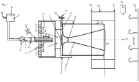
- FIG. 1 shows a device with a flow channel 1, which extends from its inlet opening 2 at the inlet end 3 to its outlet opening 4 at the outlet end 5 about a longitudinal central axis 6.
- a supply line 7 which is connected to a reservoir 8 for a liquid mass.
- an optional pump 9 is arranged as a conveyor, preferably as an alternative delivery device of the reservoir 8 is pressurized, for example by a compressed gas connection 10, and in the supply line 7, a controlled valve 11 is arranged.
- the valve 11 is controlled, in particular when the reservoir is pressurized, which may be constant, for example, depending on the signal of a detector 12 which receives the presence of a food at a position in front of the outlet 4 of the flow channel 1.
- a detector 12 may be, for example, a camera.
- the feed line 7, which is preferably a tube at least in its terminal section 14 which spans the mouth, is displaceably guided relative to the flow channel 1, eg by means of a controlled servomotor 13.
- the terminal section 14 of the feed line 7 is along the Longitudinal axis 6 of the flow channel 1 is arranged and displaceable.
- the terminal portion 14 of the supply line 7 from a first position in which its mouth is disposed in an area around the inlet opening 2 of the flow channel 1, which range from a distance in front of the inlet opening 2 and with respect to the flow channel 1 into a Distance from the inlet opening 2 may extend into the flow channel 1, for example at a distance from 0.1 mm to 30 mm, preferably from 0.2 to 10 mm from the inlet opening 2 in front of or outside the flow channel 1, controlled to a second position slidably disposed in the mouth of its mouth into the region within the flow channel 1 which is arranged downstream of at least one feed opening 15 for compressed gas and which extends in the direction of the outlet opening 4, optionally up into or over a region of the flow channel 1, where it has its smallest inner diameter, wherein the region bounded by the outlet opening 4 can be.
- the mutually perpendicular double arrows indicate the at least one displacement axis 22, optionally two mutually perpendicular displacement axes 22, which are perpendicular to the longitudinal center axis 6 of the flow channel 1, along which the supply line 7 generally in addition or alternatively to the mobility along or parallel to the longitudinal center axis. 6 slidably guided.
- the flow channel 1 has at an inlet end 3 a convex surface 16 which extends rotationally symmetrically about the longitudinal central axis 6 and tapers in the direction of the outlet end 5 to a section of smallest cross-section and subsequently widens toward the outlet opening, the cross-section being in the direction of the longitudinal central axis 6 tapers convexly from the inlet end 5 to the section of the smallest cross-section with increasing slope of the curvature and then widens conically up to the outlet opening 4, preferably in a parabolic manner.
- the pressurized gas supply port 15 is annularly disposed adjacent to the convex surface 16 at the inlet end 3 of the flow passage 1.
- This feed opening 15 is preferably arranged parallel to the adjacent convex surface 16.
- the inlet port 2 of the flow channel 1 is generally open to the atmosphere, so that gas from the environment is drawn into the inlet port 2 when pressurized gas flows through the supply port 15 into the flow channel 1.
- the compressed gas When compressed gas is supplied through the feed opening 15, the compressed gas flows along the convex surface into the flow channel 1 and forms a flow which emerges from the outlet opening 4 and at the inlet opening 2 absorbs gas from the environment, eg ambient air, into the flow channel 1.
- the supply line 7 conducts mass from the reservoir 8 to its mouth, so that the mass is detected by the gas flow in the flow channel 1 after leaving the mouth of the feed line 7 and moved through the flow channel 1.
- the gas flow can also detect mass when the Mouth of the supply line 7 is arranged in front of the inlet opening 2, since the gas flow in front of the inlet opening 2 forms a suction, which is directed into the flow channel 1.
- the supply line 7 for compressed gas is connected by means of a compressed gas line 17 with a source of compressed gas, such as a compressed gas tank or a gas compressor.
- FIG. 1 comprises an optional guide element 18 with a radial distance 19, preferably concentrically, the flow channel 1 and extends at least over the outlet end 5 of the flow channel 1.
- the guide element 18 has in FIG. 1 a constant over its length round inner cross section.
- the guide element 18 can be entrained by the flow of mass and gas that comes out of the outlet opening 4, gas from the environment.
- the guide element 18 can be acted upon with compressed gas flowing along the radial distance 19 in the direction as the flow of gas and mass in the flow channel 1.
- the guide element 18 at its first end 20, the inlet end 3 of the flow channel. 1 facing, and be open at its opposite outlet end 21.
- the transport device 23 is movable perpendicular to the longitudinal central axis 6 at a distance in front of the outlet opening 4, as indicated by the double arrow.
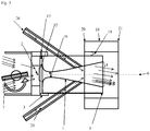
- FIG. 2 shows an embodiment in which the flow channel 1 adjacent to its inlet end 3 has a constant or cylindrical inner cross-section, at least one supply port for compressed gas within the flow channel 1 in a region which is spaced from the inlet port 2 and the outlet opening 4.
- the feed opening 15 opens at an angle to the longitudinal axis of the flow channel 1 in order to generate an air flow from the inlet opening 2 to the outlet opening 4.
- the guide element 18 is connected to pressurized gas and is designed to form a gas flow between the guide element 18 and the flow channel 1 in the direction from the inlet opening 2 to the outlet opening 4.
- the feed opening 15 can generally, as in FIG. 2 is also shown, open flush in the inner surface of the flow channel 1.
- the feed opening 15 is connected to a compressed gas line 17.
- the Flow channel 1 has a cylindrical inner cross-section, for example with the same inner diameter as the adjacent to the inlet end 3 inner cross-section or with a larger or smaller inner diameter.
- annular gap 25 may comprise the flow channel 1 and be connected to the annular radial distance 19.
- the guide element 18 forms with the annular gap 25, to which a compressed gas line is connected, a device for generating an accelerated enveloping flow around the gas flow, which emerges from the outlet opening 4.
- FIG. 3 shows an embodiment in which at least one, preferably at least two second supply lines 26 between the supply port 15 for compressed gas and the outlet opening 4 open into the flow channel 1.
- Such second supply lines 26 may be connected to a compressed gas source, a feed line 7 for a mass, powder or liquid, or at least two of these, in order to additionally press compressed gas and / or a mass in the flow channel 1.
- the second supply lines 26 preferably open in a region of the flow channel 1 between its smallest diameter and the outlet opening 4.
- FIG. 4 shows an embodiment that of that of FIG. 3 corresponds, but the second supply lines 26 protrude beyond the inner wall of the flow channel 1 in this.
- the second supply lines 26 may have an orifice that is dull or bevelled.
- FIG. 5 shows possible embodiments of the mouth of the supply line 7, at A a supply, whose mouth is perpendicular to its longitudinal axis, at B a beveled mouth B, at C a tapered mouth C, whose cross section is smaller than the cross section of the adjacent feed line 7, at D a cylindrical supply line 7, which is cut at two adjacent to the mouth D and opposite sections, for example, V-shaped or rectangular, at E an orifice E, which is arranged perpendicular to the longitudinal axis of the supply 7 and at a distance behind the mouth E at least one, preferably at least two, for example three or four holes 24 in the feed line 7.
- the supply conduit 7 may have an internal cross-section which is preferably constant to adjacent its mouth, and which optionally has a circular cross-section F or an oval cross-section G.
- the FIG. 6 shows an embodiment in which the supply line 7 can be fixed relative to the flow channel 1.
- the one end of the supply line 1 opens into a region which is spaced from the flow channel 1 and / or can end within the flow channel 1, and the other end of the supply line 7 is arranged in a reservoir 8 in order to draw from it mass.
- the negative pressure generated by the flow channel 1 acts through the supply line 7 to the end, which is arranged in the reservoir 8, and sucks the mass thereof into the supply 7.
- the flow channel 1 can be vertically aligned, in particular be arranged above a reservoir 8, wherein the supply line 7 projects into the volume of the storage container 8.
- the supply line 7 may be formed without a pump 9 therein.
Landscapes
- Chemical & Material Sciences (AREA)
- Life Sciences & Earth Sciences (AREA)
- Engineering & Computer Science (AREA)
- Food Science & Technology (AREA)
- Polymers & Plastics (AREA)
- Oil, Petroleum & Natural Gas (AREA)
- Analytical Chemistry (AREA)
- Wood Science & Technology (AREA)
- Zoology (AREA)
- General Preparation And Processing Of Foods (AREA)
Abstract
Description
- Die vorliegende Erfindung betrifft eine Vorrichtung und ein Verfahren zum Auftragen von Massen, die pulverförmig, bevorzugt flüssig mit darin verteilten Stücken sind, auf Lebensmittel. Die flüssigen Massen können wässrig oder ölig sein oder eine Emulsion. Die flüssigen Massen können eine Konsistenz aufweisen, die bei der Temperatur, bei der das Verfahren durchgeführt wird, dünnflüssig wie Wasser bis zu breiartig ist. Die Massen enthalten bevorzugt darin enthaltene Stücke, z.B. einer Größe von 0,5 mm oder von 2 mm bis zu 10 mm, bevorzugter bis 5 oder bis 3 mm in der größten Ausdehnung. Zum Auftragen auf Lebensmittel können die Stücke z.B. Gewürze, z.B. Kräuter, ganze Pfefferkörner, grob gemahlener Pfeffer, Gemüsestücke, Fleischstücke oder bei 5 bis 30°C festes Fett, pflanzlich oder tierisch, sein. Optional kann die Vorrichtung und das Verfahren eingerichtet sein, nacheinander oder gleichzeitig zumindest zwei verschiedene Massen getrennt aufzutragen, jeweils auf die gleiche oder auf gegenüberliegende Seiten des Lebensmittels, um ein mit der Masse beschichtetes Lebensmittel herzustellen.
- Die
WO00/32051 - Die
US 3,436,230 beschreibt Düsen, mit denen ohne Einstechen Flüssigkeit mit so hohem Druck in Fleisch gespritzt werden kann, dass dessen Oberfläche nicht beschädigt werden soll, z.B. mit Geschwindigkeiten von ca. 180 m/s. - Der Erfindung stellt sich die Aufgabe, eine alternative Vorrichtung und ein damit durchführbares Verfahren zum Auftragen von Massen auf Lebensmittel bereitzustellen, die insbesondere geeignet sind, flüssige Massen, die Stücke enthalten, berührungslos aufzutragen, insbesondere mittels eines Gasstroms aufzutragen.
- Die Erfindung löst die Aufgabe mit den Merkmalen der Ansprüche und stellt insbesondere eine Vorrichtung zur Verwendung als Auftragvorrichtung für Massen auf Lebensmittel und ein damit durchführbares Verfahren zur Herstellung von beschichteten Lebensmitteln durch Auftragen einer Masse auf Lebensmittel bereit, mit einem Strömungskanal, an dessen Einlassende eine Zuführleitung für die Masse angeordnet ist, deren Mündung in einem Bereich festgelegt ist, der sich von einem Abstand vor dem Einlassende bis in den Strömungskanal erstreckt.
- In einer Ausführungsform, die vorteilhafterweise einfach herzustellen und einfach im Verfahren zu betreiben ist, weist die Vorrichtung einen Strömungskanal auf, der mit zumindest einem Druckgasanschluss versehen ist, und eine Zuführleitung, die, bevorzugt koaxial zum Strömungskanal, in einem Bereich mündet, in dem der Strömungskanal Unterdruck erzeugt, wobei sich dieser Bereich von einem Abstand vor der Eintrittsöffnung bis innerhalb des Strömungskanals erstreckt, oder besteht daraus. Dabei kann die Zuführleitung mit ihrem gegenüberliegenden offenen Ende in einen Behälter für die Masse ragen und bevorzugt keine Fördereinrichtung aufweisen. Dabei kann die Vorrichtung unterhalb einer Transporteinrichtung angeordnet sein, z.B. mit der Längsachse des Strömungskanals vertikal und dessen Austrittsöffnung oben. In dieser Ausführungsform ist die Zuführleitung festgelegt und die Anordnung ihrer Mündung in einem Bereich, in dem der Strömungskanal Vakuum erzeugt, erlaubt das selbsttätige Ansaugen der Masse. Die Zuführleitung kann in einem Abstand zur Längsmittelachse des Strömungskanals angeordnet sein oder koaxial zum Strömungskanal. Dabei kann die Zuführleitung in einem Winkel oder parallel zur Längsmittelachse des Strömungskanals angeordnet sein. Bevorzugt ist die Mündung der Zuführleitung koaxial zum Strömungskanal angeordnet. Dabei kann der Behälter für die Masse ein oben offener Behälter sein, der unterhalb der Transporteinrichtung angeordnet ist, optional so, dass aus Richtung der Transporteinrichtung nach unten fallende Masse in den Behälter fällt.
- Optional ist die Zuführleitung verschieblich und/oder schwenkbar geführt und in einer Stellung festlegbar, so dass ihre Mündung in einem Bereich anordnbar ist, der sich von einem Abstand vor dem Einlassende bis in den Strömungskanal erstreckt. Weiter optional ist die Mündung der Zuführleitung koaxial zur Längsmittelachse des Strömungskanals angeordnet.
- Die Zuführleitung ist optional mit einem Vorratsbehälter für eine Masse verbunden, optional mit zumindest zwei Vorratsbehältern mit jeweils einer Zuleitung und einem Ventil, das zwischen den Vorratsbehältern umschalten und einen Vorratsbehälter mit der Zuführleitung verbinden kann, verbunden. Jeder Vorratsbehälter kann mittels einer Leitung mit der Zuführleitung verbunden sein, die in Bereich mündet, der sich von einem Abstand vor der Einlassöffnung des Strömungskanals bis innerhalb des Strömungskanals erstreckt.
- Bevorzugt ist in jeder Leitung und/oder in der Zuführleitung eine gesteuerte Fördereinrichtung zur Förderung der Masse zur Mündung der Zuführleitung angeordnet. Für flüssige Massen ist die Fördereinrichtung z.B. eine Pumpe oder Verdrängerpumpe, bevorzugt eine Kolben- oder Exzenterschneckenpumpe, Schlauchpumpe oder Kreisel-, Schnecken -, Membran-, Impeller-, Drehkolben-, Drehschieber-, Kreiskolben- oder Zahnradpumpe. Als eine alternative Fördereinrichtung kann ein Vorratsbehälter unter Druck gesetzt werden, z.B. durch Beaufschlagen des Vorratsbehälters mit Druckgas, z.B. Druckluft mittels eines Druckluftanschlusses, bevorzugt von konstantem Druck, oder durch Ausbilden einer Behälterwand, z.B. des Deckels, als ein gegen das Innenvolumen des Vorratsbehälters belasteter Kolben. Insbesondere in Ausführungsformen, in denen die Fördereinrichtung dadurch gebildet ist, dass der Vorratsbehälter mit Druck beaufschlagt ist, ist bevorzugt ein steuerbares Ventil in der Zuführleitung angeordnet. Ein solches Ventil in der Zuführleitung kann z.B. abhängig von der Position einer Transporteinrichtung gesteuert sein, an der Lebensmittel in einem Abstand vor der Austrittsöffnung des Strömungskanals vorbei transportiert werden, oder abhängig vom Signal eines Detektors für die Anwesenheit eines an der Transporteinrichtung angeordneten Lebensmittels vor der Austrittsöffnung des Strömungskanals. Ein solcher Detektor kann eine Photozelle, bevorzugt eine Kamera sein.
- Für pulverförmige Massen ist die Fördereinrichtung z.B. eine Förderschnecke, eine Schütte oder ein Gebläse.
- Optional ist in der Zuführleitung für die Masse keine Fördereinrichtung angeordnet und optional bewirkt oder unterstützt allein der Strömungskanal die Förderung der Masse an die Mündung der Zuführleitung, insbesondere durch den vom Strömungskanal erzeugten Unterdruck, der auf die Mündung der Zuführleitung wirkt. Mit oder ohne Fördereinrichtung in der Zuführleitung kann der vom Strömungskanal erzeugte Unterdruck, der auf die Mündung der Zuführleitung wirkt, die Förderung der Masse durch die Zuführleitung bewirken oder unterstützen. Weiter optional ist ein Vorratsbehälter, bevorzugt alle Vorratsbehälter, für Masse oberhalb der Mündung der Zuführleitung angeordnet, so dass die Masse durch die Schwerkraft zur Mündung gefördert wird. Dabei ist in jeder Ausführungsform bevorzugt ein gesteuertes Ventil in der Zuführleitung angeordnet. Alternativ weist die Zuführleitung kein Ventil auf.
- Optional ist die Fördereinrichtung oder die Zuführleitung mit einem Durchflussmengenmesser versehen.
- Die Zuführleitung ist optional relativ zum Strömungskanal verschieblich geführt und in einer Stellung festlegbar, bevorzugt koaxial zur Längsmittelachse des Strömungskanals angeordnet und entlang dieser Längsmittelachse verschieblich geführt, insbesondere relativ zum Einlassende des Strömungskanals.
- Optional ist die Zuführleitung in einem Winkel zur Längsmittelachse des Strömungskanals angeordnet und festgelegt oder in einen Winkel zur Längsmittelachse des Strömungskanals schwenkbar und in einer Stellung festlegbar. Optional ist die Zuführleitung, parallel oder in einem Winkel zur Längsmittelachse des Strömungskanals angeordnet und festgelegt und/oder die Zuführleitung ist in einen Winkel schwenkbar zur Längsmittelachse des Strömungskanals, in einer oder in zwei Dimensionen, die senkrecht zur Längsmittelachse stehen, verschieblich und/oder schwenkbar geführt und bevorzugt in einer Stellung festlegbar.
- Eine zur Längsmittelachse verschiebliche Zuführleitung, z.B. mittels eines oder zweier Linearführungen, die entlang einer bzw. zweier Achsen senkrecht zur Längsmittelachse des Strömungskanals eine Führung für die Zuführleitung bilden, mittels derer die Zuführleitung verschieblich geführt ist, erlaubt die in verschiedene Stellungen gesteuerte exzentrische Zuführung der Masse in den Strömungskanal. Auf diese Weise ist die Vorrichtung eingerichtet, die Verteilung der Masse gesteuert zu variieren, z.B. die Verteilung der stückigen Bestandteile gesteuert zu beeinflussen. Die Zuführleitung kann z.B. mittels zumindest einer Einstellschraube oder zumindest eines Linearantriebs relativ zum Strömungskanal verschieblich geführt sein.
- Generell kann die Zuführleitung in Ausführungsformen, in denen sie festgelegt ist bzw. nicht verschieblich und/oder schwenkbar ist, mit ihrer Mündung in einer Stellung festgelegt sein, die mit Bezug auf die Ausführungsform beschrieben ist, in der die Zuführleitung veschieblich und/oder schwenkbar und bevorzugt in einer Stellung festlegbar ist. Die Zuführleitung kann z.B. über einen Bereich relativ zum Strömungskanal verschieblich oder innerhalb eines Bereichs festgelegt sein, der sich von einer Stellung, in der die Mündung der Zuführleitung in einem Abstand von der Ebene der Einlassöffnung bzw. vom Einlassende außerhalb des Strömungskanals angeordnet ist, bis in eine Stellung erstreckt, in der die Mündung der Zuführleitung innerhalb des Strömungskanals angeordnet ist, z.B. bis in eine Stellung, in der die Mündung bis in den Abschnitt des Strömungskanals mit dem geringsten Innendurchmesser oder darüber hinaus in den Strömungskanal ragt. Optional kann die Zuführleitung verschieblich sein, so dass ihre Mündung in einem Bereich angeordnet ist, der sich von einem Abstand von der Ebene der Einlassöffnung außerhalb des Strömungskanals über die Ebene der Einlassöffnung z.B. bis zu dem Abschnitt des Strömungskanals mit dem geringsten Innendurchmesser erstreckt, oder z.B. in einem Bereich, der sich von der Ebene der Einlassöffnung bis zur Zuführöffnung für Druckgas, die am oder im Strömungskanal angeordnet ist, erstreckt, oder in einem Bereich, der sich von der Zuführöffnung für Druckgas bis zur Austrittsöffnung des Strömungskanals erstreckt. Auch in Ausführungsformen des Strömungskanals, in denen dieser einen über seine Länge konstanten Durchmesser oder einen von der Einlassöffnung zur Austrittsöffnung zunehmenden Durchmesser aufweist, kann die Zuführleitung verschieblich sein, dass ihre Mündung in einem Bereich positionierbar ist, der sich von einem Abstand vor der Einlassöffnung bis zur Zuführöffnung für Druckgas in dem Strömungskanal erstreckt, oder in einem Bereich positionierbar ist, der sich von der Zuführöffnung für Druckgas bis zur Austrittsöffnung erstreckt.
- Optional kann die Stellung der Mündung der Zuführleitung relativ zum Strömungskanal abhängig z.B. vom Druck und/oder von der Geschwindigkeit und/oder dem Massestrom der aus der Zuführleitung austretenden Masse oder von der Förderrate einer Fördereinrichtung gesteuert sein, die der Druck sein kann, mit dem der Vorratsbehälter beaufschlagt ist, oder abhängig von der Förderleistung einer in der Zuführleitung angeordneten Pumpe und/oder abhängig von der Stellung eines in der Zuführleitung angeordneten Ventils.
- Der Strömungskanal weist zumindest eine angeschlossene Druckgasleitung auf, die mittels eines Ventils gesteuert ist und an dem Strömungskanal in zumindest einer Zuführöffnung für Druckgas mündet, die eingerichtet ist, in dem Strömungskanal eine Luftströmung vom Einlassende zum gegenüberliegenden Auslassende zu beschleunigen. Optional ist das Ventil gesteuert, abhängig vom Signal eines Detektors für die Stellung eines Lebensmittels auf der Transporteinrichtung für Lebensmittel.
- Optional ist die Zufuhr von Druckgas zur Zuführöffnung gesteuert, z.B. ist die Zufuhr von Druckgas abhängig von einem Signal eines Detektors für die Anwesenheit eines an der Transporteinrichtung angeordneten Lebensmittels vor der Austrittsöffnung des Strömungskanals geöffnet, so dass nur bei Detektion eines Lebensmittels vor der Austrittsöffnung Druckgas gesteuert in den Strömungskanal geführt wird. Weiter optional ist die Zufuhr von Druckgas abhängig von einem Signal eines Durchflussmessers gesteuert. Generell kann das Druckgas der zumindest einen Zuführöffnung mit einem Druck von 0,1 bis 15 bar, z.B. 0,1 bis 10 bar zugeführt werden. Optional kann das Druckgas stoßweise zugeführt werden, z.B. in Stößen einer Dauer von 10 bis 3000 ms und einer Frequenz von bis zu 3000 Stößen/min (ca. 50 pro Sekunde). Dazu kann die Vorrichtung eingerichtet sein, ein Ventil in der Druckgasleitung gesteuert stoßweise zu öffnen. Alternativ kann die Vorrichtung eingerichtet sein, dass das Druckgas kontinuierlich der zumindest einen Zuführöffnung zugeführt wird.
- In einer bevorzugten Ausführungsform wird die Einlassöffnung am Einlassende des Strömungskanals von einer konvexen Fläche aufgespannt, die sich rotationssymmetrisch um die Längsmittelachse des Strömungskanals erstreckt und bevorzugt eine zur Längsmittelachse des Strömungskanals vorstehende Krümmung bzw. eine konvexe Fläche aufweist, die bevorzugt parabelförmig ist. Optional steht die Krümmung bzw. konvexe Fläche entlang des Radius zur Längsmittelachse des Strömungskanals vor. Bevorzugt nimmt die Steigung der Krümmung in Richtung auf die Längsmittelachse des Strömungskanals zu, so dass bevorzugt die Steigung mit abnehmendem Radius größer wird, um eine zur Längsmittelachse zunehmende Krümmung zu bilden. Der Strömungskanal weist im Anschluss daran, z.B. im Anschluß an die konvexe Fläche, und gegenüber der Einlassöffnung, bzw. des Einlassendes, seinen kleinsten Querschnitt auf und weitet sich ab diesem kleinsten Querschnitt in Richtung zur Austrittsöffnung bzw. auf sein Auslassende, das dem Einlassende gegenüber liegt, vorzugsweise mit konisch oder parabelförmig zunehmendem Querschnitt. Das Einlassende, das die Öffnung des Strömungskanals bildet, wird von einer ringförmigen Zuführöffnung für Druckgas begrenzt, die mit der Druckgasleitung verbunden ist. Dabei ist die ringförmige Zuführöffnung durch eine von der Fläche, die die Einlassöffnung bildet und die bevorzugt konvex ist, beabstandete Schulter gebildet, sodass der Querschnitt der Zuführöffnung in einem an die Öffnung des Einlassendes angrenzenden Abschnitt angeordnet ist, vorzugsweise die Zuführöffnung einen axialen Abschnitt entlang der Längsmittelachse des Strömungskanals bildet. Die Schulter ist vorzugsweise ringförmig, sodass sie mit der beabstandeten konvexen Fläche, die die Einlassöffnung am Einlassende aufspannt, eine ringförmige Zuführöffnung für Druckgas um die Längsmittelachse des Strömungskanals bildet. Generell kann die zumindest eine Austrittsöffnung für Druckgas in Form zumindest einer Bohrung oder eines Röhrchens in der Wandung des Strömungskanals in einem Winkel von maximal 90°, maximal 75°, bevorzugt maximal 45° oder maximal 30° oder maximal 15° oder maximal 5° vom Einlassende her zur Längsmittelachse angeordnet sein. Da sich in dieser Ausführungsform der Durchmesser des Strömungskanals zu seinem Auslassende bzw. zu seiner Austrittsöffnung vergrößert, bildet der Strömungskanal keine Düse, deren Durchmesser sich zum Auslassende verkleinert, sondern optional eine Laval-Düse, um den Druck des eingesetzten Druckgases in Gasgeschwindigkeit umzusetzen.
- In einer alternativen Ausführungsform kann der Strömungskanal zumindest abschnittsweise einen zylindrischen Innenquerschnitt aufweisen, optional mit einem über seine Länge konstanten Durchmesser oder mit abschnittsweise vom seinem Einlassende zum Auslassende zunehmenden oder abnehmenden Durchmesser. Die zumindest eine Austrittsöffnung für Druckgas kann z.B. in Form zumindest einer Bohrung oder eines Röhrchens in der Wandung des Strömungskanals in einem Winkel von maximal 75°, bevorzugt maximal 45° oder maximal 30° oder maximal 5° vom Einlassende her zur Längsmittelachse angeordnet sein. In dieser Ausführungsform reißt Druckgas, das durch die Zuführöffnung für Druckgas in den Strömungskanal strömt, die Luft in dem Strömungskanal mit und beschleunigt sie zur Austrittsöffnung.
- Generell ist der Strömungskanal an seinem Einlassende zu Umgebung offen, so dass Gas aus der Umgebung in den Strömungskanal gesaugt werden kann, wenn der Strömungskanal mit Druckgas beaufschlagt wird, das durch die zumindest eine Zuführöffnung für Druckgas in den Strömungskanal einströmen gelassen wird.
- Der Strömungskanal ist mit seiner Längsmittelachse und seiner Austrittsöffnung auf eine Transporteinrichtung für Lebensmittel gerichtet. Bevorzugt ist zumindest ein Strömungskanal auf jeder Seite der Transporteinrichtung angeordnet und auf diese gerichtet. Die Transporteinrichtung kann ein etwa horizontal laufendes Transportband mit Durchbrüchen sein, z.B. ein umlaufendes Gitterband oder parallel umlaufende beabstandete Bandelemente, und ein Strömungskanal kann von oben und ein weiterer Strömungskanal kann von unten gegen das Transportband gerichtet sein. Alternativ kann die Transporteinrichtung eine Reihe beweglicher Hänger, z.B. Haken sein, an die Lebensmittel angehängt werden können, und jeweils zumindest ein Strömungskanal kann von jeder Seite gegen einen Bereich der Transporteinrichtung oder gegen einen Bereich unterhalb der Transporteinrichtung gerichtet sein, in dem das Lebensmittel angeordnet ist.
- Optional kann der Strömungskanal an seinem Auslassende von einem Leitelement vollständig oder teilweise umfasst sein, der in einem radialen Abstand vom Strömungskanal angeordnet ist und sich koaxial zur Längsmittelachse des Strömungskanals erstreckt, z.B. einem Rohrabschnitt, der sich koaxial und mit radialem Abstand um das Auslassende bzw. um die Austrittsöffnung erstreckt. Das Leitelement kann einen konstanten Innendurchmesser aufweisen, einen in Strömungsrichtung abnehmenden Innendurchmesser oder einen in Strömungsrichtung abnehmenden Innendurchmesser, der sich anschließend zu seinem Auslass vergrößert. Ein von einem Leitelement zumindest an seinem Auslassende umfasster Strömungskanal erlaubt eine Fokussierung des austretenden Massestrahls, so dass die Masse genauer auf das Lebensmittel aufgetragen werden kann.
- Optional kann das Leitelement mit Druckgas beaufschlagt werden, das eine Gasströmung zwischen dem Leitelement und dem Strömungskanal ausbildet. Ein mit Druckgas beaufschlagtes Leitelement kann an seinem dem Auslassende bzw. der Austrittsöffnung gegenüberliegenden Ende geschlossen oder offen sein. Zur Beaufschlagung mit Druckgas, das eine Gasströmung zwischen dem Leitelement und dem Strömungskanal in Richtung vom Einlassende bzw. der Einlassöffnung zum Auslassende bzw. zur Austrittsöffnung des Strömungskanals bzw. in Richtung der Strömung von Gas und Masse innerhalb des Strömungskanals ausbildet, weist das Leitelement z.B. zumindest einen, vorzugsweise zumindest zwei um seinen Umfang verteilte Zuführöffnungen für Druckgas auf. Das Leitelement kann bei Beaufschlagung mit Druckgas einen Hüllstrom um den aus dem Strömungskanal austretenden Strom aus Gas und Masse bilden. Ein solcher Hüllstrom kann die Ausrichtung und Geschwindigkeit des Stroms aus Gas und Masse erhöhen, z.B. diesen Strom fokussieren, der aus dem Strömungskanal austritt.
- Optional ist das Druckgas, mit dem das Leitelement beaufschlagt wird, und/oder das Druckgas, mit dem der Strömungskanal beaufschlagt wird, ionisiert. Für die Ionisierung des Druckgases kann eine Ionisierungseinrichtung vorgesehen sein, z.B. zwischen der jeweiligen Druckgasleitung und dem Leitelement bzw. dem Strömungskanal.
- Weiter optional kann das Druckgas, mit dem das Leitelement beaufschlagt wird, und/oder das Druckgas, mit dem der Strömungskanal beaufschlagt wird, gekühlt sein, z.B. auf eine Temperatur von -120 bis +250°C temperiert sein. Dazu kann die Druckgasleitung und/oder die Druckgasquelle gekühlt sein bzw. dazu eingerichtet sein, das Druckgas bei einer solchen Temperatur zur Verfügung zu stellen. Druckgas ist optional Luft oder Stickstoff oder Kohlendioxid oder eine Mischung aus zumindest zweien dieser.
- Es hat sich gezeigt, dass ein Verfahren zum Auftragen flüssiger Massen mittels der erfindungsgemäßen Vorrichtung dazu führt, dass die auf das Lebensmittel aufgetragene Masse eine gleichmäßige Verteilung auch der festen Inhaltsstoffe in der Beschichtung auf dem Lebensmittel aufweist. Weiterhin hat sich gezeigt, dass die auf das Lebensmittel aufgetragene Masse Gaseinschlüsse aufweist, die bei anschließendem Einfrieren zumindest zum Teil erhalten bleiben und bevorzugt der aufgetragenen Masse den Eindruck eines großen Volumens verleihen.
- Die Vorrichtung und das Verfahren eignen sich insbesondere zum Auftragen flüssiger Massen, die bevorzugt darin verteilte Stücke aufweisen, mit einer dynamischen Viskosität im Bereich von 0,5 mPas bis 200 Pas, z.B. 50 bis 200 oder bis 150 Pas, oder bis 1x10⁴ mPas bei der Temperatur, bei der das Verfahren durchgeführt wird, gemessen bei einer Scherrate von 1/s in einem Rotationsviskosimeter. Die Temperatur, bei der das Verfahren durchgeführt wird, liegt z.B. bei -80 °C bis 310°C oder bis 15 °C, bevorzugt bei bis zu 5°C, z.B. bei -20°C bis 3°C oder bei -5°C oder 0°C bis 5°C oder bis 3°C. Bevorzugt ist die Masse, optional das in den Strömungskanal zugeführte Druckgas, auf eine Temperatur in dem Bereich temperiert, bei dem das Verfahren durchgeführt wird. Alternativ kann die Masse unabhängig von der Temperatur, bei der das Verfahren durchgeführt wird, auf +310°C bis -80°C , z.B. auf -20 °C bis 310°C oder bis 15 °C, bevorzugt bis zu 5°C, z.B. auf -20°C bis 3°C oder auf -5°C oder 0°C bis 5°C oder bis 3°C temperiert sein. Das Durchführen des Verfahrens und das Temperieren der Masse auf eine Temperatur unterhalb von 0°C ist z.B. für Öl und Emulsionen bevorzugt, um diese in größerer Schichtdicke aufzutragen und/oder um für die in der Masse enthaltenen Stücke eine gleichmäßige Verteilung und/oder ein gutes Anhaften zu erzielen.
- Für das Temperieren der Masse kann z.B. bevorzugt der Vorratsbehälter auf diese Temperatur gekühlt sein. Die Viskosität kann mit bekannten Mitteln eingestellt werden, z.B. durch Zusetzen von Verdickungsmitteln und/oder feinverteilten Inhaltsstoffen zu der Masse.
- Optional weist die Vorrichtung eine Gefriereinrichtung auf, durch die die Lebensmittel vor und/oder nach dem Auftragen der Masse transportiert werden. Eine Gefriereinrichtung, die eingerichtet ist, die Lebensmittel vor dem Auftragen der Masse auf eine Temperatur von kleiner als 0°C, z.B. auf eine Temperatur im Bereich von -70 bis -5°C oder bis -20 °C zu kühlen, kann die Transporteinrichtung in einem Bereich nur vor dem Bereich umfassen, in dem der Strömungskanal auf die Transporteinrichtung gerichtet ist, oder kann auch den Bereich umfassen, in dem der Strömungskanal auf die Transporteinrichtung gerichtet ist. Entsprechend können im Verfahren die Lebensmittel vor dem Auftragen der Masse auf eine Temperatur von kleiner als 0°C, z.B. auf eine Temperatur im Bereich von -70 bis -5°C oder bis -20 °C gekühlt werden, optional können die Lebensmittel auch während des Auftragens der Masse auf eine Temperatur von kleiner als 0°C, z.B. auf eine Temperatur im Bereich von -70 bis -5°C oder bis -20 °C gekühlt werden. Auf diese Weise kann das Anhaften der aufgetragenen Masse, optional mit Gaseinschlüssen, an den Lebensmitteln erhöht werden. Entsprechend ist die Vorrichtung zur Verwendung als Auftragsvorrichtung von flüssigen Massen auf Lebensmittel geeignet, die auf eine Temperatur von kleiner als 0°C, z.B. auf eine Temperatur im Bereich von -70 bis -5°C oder bis -20 °C gekühlt sind.
- Bevorzugt weist die Vorrichtung eine Kühleinrichtung auf, die eingerichtet ist, die Lebensmittel im Anschluß an das Auftragen der Masse auf eine Temperatur von kleiner als 0°C, z.B. auf eine Temperatur im Bereich von -70 bis -5°C oder bis -20 °C zu kühlen. Im Verfahren wird die zumindest eine Masse, die pulverförmig, bevorzugt flüssig, homogen oder flüssig mit darin enthaltenen Stücken ist, wobei die Stücke bevorzugt eine Größe oder Größenverteilung von 0,1 mm bis 0,5 oder von 0,5 bis 4 mm, z.B. von 2 mm bis zu 10 mm, bevorzugter bis 5 oder bis 3 mm in der größten Ausdehnung aufweisen, durch die Mündung der Zuführleitung geführt, wobei die Zuführleitung parallel oder in einem Winkel zur Längsmittelachse des Strömungskanals geneigt ist oder in einen Winkel zur Längsmittelachse des Strömungskanals verschwenkt wird, optional entlang einer oder zweier Achsen, die senkrecht zur Längsmittelachse des Strömungskanals stehen, oder nur koaxial zur Längsmittelachse des Strömungskanals verschoben und in einer Stellung festgelegt wird, in der ihre Mündung in einem Bereich angeordnet ist, der sich von einem Abstand vor dem Einlassende bzw. vor der Einlassöffnung des Strömungskanals bis in diesen erstreckt, z.B. bis in dessen Abschnitt geringsten Durchmessers oder bis vor die zumindest eine Zuführöffnung für Druckgas erstreckt, oder in einem Bereich, der sich von der Zuführöffnung für Druckgas bis zur Austrittsöffnung des Strömungskanals erstreckt.
- Während des Verfahrens wird Druckgas durch die zumindest eine Zuführöffnung für Druckgas an oder in den Strömungskanal geführt, so dass in dem Strömungskanal Gas von der Einlassöffnung zur Austrittsöffnung strömt und dabei Gas aus der Umgebung in die Einlassöffnung saugt. Die durch die Zuführleitung geleitete Masse tritt in die Strömung vor der Einlassöffnung des Strömungskanals oder in die Strömung innerhalb des Strömungskanals ein und tritt mit dem zugeführten Druckgas und in die Einlassöffnung eingesaugtem Gas aus der Umgebung anschließend aus der Austrittsöffnung des Strömungskanals. Dieser austretende Strom wird auf die Lebensmittel gerichtet, die mittels einer Transporteinrichtung in einem Abstand von der Austrittsöffnung an der Austrittsöffnung vorbeigeführt werden. Vorzugsweise läuft die Transporteinrichtung kontinuierlich und die Masse wird auf die an der Transporteinrichtung kontinuierlich transportierten Lebensmittel aufgetragen.
- Optional wird Druckgas in den Zwischenraum zwischen einem Leitelement, das in einem Abstand die Austrittsöffnung des Strömungskanals umfasst, strömen gelassen und/oder Gas aus der Umgebung, z.B. Umgebungsluft, wird durch das offene Ende dieses Zwischenraums strömen gelassen. Dabei bewegt sich das Druckgas in dem Zwischenraum und/oder das aus der Umgebung in den Zwischenraum eingeströmte Gas zwischen dem Leitelement und dem Strömungskanal in der Richtung vom Einlassende zum Auslassende des Strömungskanals und kann einen Hüllgasstrom um die aus der Austrittsöffnung tretende Masse und das austretende Gas bilden.
- Optional kann die Vorrichtung eine Einrichtung zum Fördern einer weiteren Masse aufweisen, die pulverförmig oder flüssig sein kann, in den Abstand zwischen dem Leitelement und dem Strömungskanal. Dabei wird zusätzlich zu dem Druckgas eine weitere pulverförmige oder flüssige Masse in den Hüllstrom eingebracht.
- Optional kann die Vorrichtung zumindest eine, bevorzugt zumindest zwei zweite Zuführungsleitungen aufweisen, die zwischen der Zuführöffnung für Druckgas und der Austrittsöffnung in den Strömungskanal münden. Solche zweiten Zuführungsleitungen können mit einer Druckgasquelle, einer Zuführleitung für eine Masse, pulverförmig oder flüssig, oder zumindest zweien dieser verbunden sein, um zusätzlich Druckgas und/oder eine Masse vor der Austrittsöffnung in den Strömungskanal zu drücken. Dabei können die zweiten Zuführungsleitungen in einem Bereich des Strömungskanals zwischen der Zuführöffnung für Druckgas in den Strömungskanal und dessen Austrittsöffnung münden, optional zwischen dem geringsten Durchmesser des Strömungskanals und der Austrittsöffnung münden.
- Die zweiten Zuführleitungen können über die Innenwand des Strömungskanals in diesen ragen oder bündig in der Innenwand des Strömungskanals münden. Generell können die zweiten Zuführleitungen eine Mündung aufweisen, die stumpf oder abgeschrägt ist.
- Optional ist ein Ventil in der Zuführleitung für die Masse und/oder ein Ventil in der Druckgasleitung, die in zumindest einer Zuführöffnung für Druckgas an oder in dem Strömungskanal mündet, abhängig von einem Detektor gesteuert, der die Stellung von Lebensmitteln auf der Transporteinrichtung aufnimmt.
- Die Erfindung wird nun genauer mit Bezug auf die Figuren beschrieben, die schematisch in
-
Figur 1 eine Ausführungsform der erfindungsgemäßen Vorrichtung, -
Figur 2 eine weitere Ausführungsform der erfindungsgemäßen Vorrichtung und -
Figur 3 eine weitere Ausführungsform der erfindungsgemäßen Vorrichtung, -
Figur 4 eine weitere Ausführungsform der erfindungsgemäßen Vorrichtung, -
Figur 5 mögliche Ausführungsformen der Zuführleitung und -
Figur 6 eine Ausführungsform der erfindungsgemäßen Vorrichtung zeigen. - In den Figuren sind Ausführungsformen dargestellt, in denen die Zuführleitung verschieblich bzw. schwenkbar ist und in einer Stellung festlegbar ist. Dabei zeigen die Stellungen, in die die Zuführleitung verschieblich bzw. schwenkbar ist, die Stellungen an, in denen die Mündung der Zuführleitung in Ausführungsformen angeordnet sein kann, in denen die Zuführleitung festgelegt ist, bzw. nicht verschieblich und nicht schwenkbar ist.
- Die
Figur 1 zeigt eine Vorrichtung mit einem Strömungskanal 1, der sich von seiner Einlassöffnung 2 am Einlassende 3 zu seiner Austrittsöffnung 4 am Auslassende 5 um eine Längsmittelachse 6 erstreckt. An der Einlassöffnung 2 mündet eine Zuführleitung 7, die mit einem Vorratsbehälter 8 für eine flüssige Masse verbunden ist. In der Zuführleitung 7 ist eine optionale Pumpe 9 als Fördereinrichtung angeordnet, bevorzugt ist alternativ als Fördereinrichtung der Vorratsbehälter 8 mit Druck beaufschlagt, z.B. durch einen Druckgasanschluß 10, und in der Zuführleitung 7 ist ein gesteuertes Ventil 11 angeordnet. Das Ventil 11 ist, insbesondere bei Beaufschlagung des Vorratsbehälters mit Druck, der z.B. konstant sein kann, abhängig vom Signal eines Detektors 12 gesteuert, der die Anwesenheit eines Lebensmittels an einer Position vor der Austrittsöffnung 4 des Strömungskanals 1 aufnimmt. Ein solcher Detektor 12 kann z.B. eine Kamera sein. - Die Zuführleitung 7, die bevorzugt zumindest in seinem endständigen Abschnitt 14, der die Mündung aufspannt, ein Rohr ist, ist relativ zum Strömungskanal 1 verschieblich geführt, z.B. mittels eines gesteuerten Stellmotors 13. Wie bevorzugt, ist der endständige Abschnitt 14 der Zuführleitung 7 entlang der Längsmittelachse 6 des Strömungskanals 1 angeordnet und verschieblich. Bevorzugt ist der endständige Abschnitt 14 der Zuführleitung 7 von einer ersten Position, in der seine Mündung in einem Bereich um die Einlassöffnung 2 des Strömungskanals 1 angeordnet ist, wobei sich dieser Bereich von einem Abstand vor der Einlassöffnung 2 und gegenüber dem Strömungskanal 1 bis in einen Abstand von der Einlassöffnung 2 in den Strömungskanal 1 erstrecken kann, z.B. in einem Abstand von 0,1 mm bis 30 mm, bevorzugt von 0,2 bis 10 mm von der Einlassöffnung 2 vor dem bzw. außerhalb des Strömungskanals 1, bis in eine zweite Position gesteuert verschieblich, in der seine Mündung bis in den Bereich innerhalb des Strömungskanals 1 angeordnet ist, der stromabwärts zumindest einer Zuführöffnung 15 für Druckgas angeordnet ist und der sich in Richtung der Austrittsöffnung 4 erstreckt, optional bis in oder über einen Bereich des Strömungskanals 1 hinaus, an dem dieser seinen geringsten Innendurchmesser aufweist, wobei der Bereich durch die Austrittsöffnung 4 begrenzt sein kann. Die senkrecht zueinander stehenden Doppelpfeile deuten die zumindest eine Verschiebeachse 22, optional zwei senkrecht zueinander stehende Verschiebeachsen 22 an, die senkrecht zur Längsmittelachse 6 des Strömungskanals 1 stehen, entlang derer die Zuführleitung 7 generell zusätzlich oder alternativ zur Verschieblichkeit entlang der oder parallel zu der Längsmittelachse 6 verschieblich geführt ist.
- In der in
Figur 1 gezeigten Ausführungsform weist der Strömungskanal 1 an einem Einlassende 3 eine konvexe Fläche 16 auf, die sich rotationssymmetrisch um die Längsmittelachse 6 erstreckt und in Richtung auf das Auslassende 5 zu einem Abschnitt kleinsten Querschnitts verjüngt und sich anschließend zur Austrittsöffnung aufweitet, wobei der Querschnitt in Richtung auf die Längsmittelachse 6 sich vom Einlassende 5 konvex zum Abschnitt kleinsten Querschnitts mit zunehmender Steigung der Krümmung verjüngt und sich anschließend bis zur Austrittsöffnung 4 konisch, bevorzugt parabelförmig aufweitet. Die Zuführöffnung 15 für Druckgas ist ringförmig angrenzend an die konvexe Fläche 16 am Einlassende 3 des Strömungskanals 1 angeordnet. Diese Zuführöffnung 15 ist bevorzugt parallel zu der angrenzenden konvexen Fläche 16 angeordnet. Die Einlassöffnung 2 des Strömungskanals 1 ist generell zur Umgebung hin offen, so dass Gas aus der Umgebung in die Einlassöffnung 2 gesaugt wird, wenn Druckgas durch die Zuführöffnung 15 in den Strömungskanal 1 strömt. - Bei Zufuhr von Druckgas durch die Zuführöffnung 15 strömt das Druckgas entlang der konvexen Fläche in den Strömungskanal 1 und bildet eine Strömung aus, die aus der Austrittsöffnung 4 austritt und an der Einlassöffnung 2 Gas aus der Umgebung, z.B. Umgebungsluft, in den Strömungskanal 1 einsaugt. Die Zuführleitung 7 leitet Masse aus dem Vorratsbehälter 8 bis an ihre Mündung, so dass die Masse nach Austreten aus der Mündung der Zuführleitung 7 von der Gasströmung in dem Strömungskanal 1 erfasst und durch den Strömungskanal 1 bewegt wird. Dabei kann die Gasströmung auch Masse erfassen, wenn die Mündung der Zuführleitung 7 vor der Einlassöffnung 2 angeordnet ist, da die Gasströmung vor der Einlassöffnung 2 einen Sog ausbildet, der in den Strömungskanal 1 gerichtet ist. Entsprechend strömt beim Verfahren ein Strom aus Druckgas, Masse und angesaugtem Gas entlang des Strömungskanals 1 und tritt aus dessen Austrittsöffnung 4 aus. Die Zuführleitung 7 für Druckgas ist mittels einer Druckgasleitung 17 mit einer Quelle für Druckgas verbunden, z.B. einem Druckgasbehälter oder einem Gasverdichter.
- In
Figur 1 umfasst ein optionales Leitelement 18 mit radialem Abstand 19, bevorzugt konzentrisch, den Strömungskanal 1 und erstreckt sich zumindest über das Auslassende 5 des Strömungskanals 1. Das Leitelement 18 weist inFigur 1 einen über seine Länge konstanten runden Innenquerschnitt auf. In dem radialen Abstand 19 zwischen dem Strömungskanal 1 und dem Leitelement 18 kann durch den Strom aus Masse und Gas, das aus der Austrittsöffnung 4 tritt, Gas aus der Umgebung mitgerissen werden. Optional kann das Leitelement 18 mit Druckgas beaufschlagt werden, das entlang des radialen Abstands 19 in der Richtung strömt, wie der Strom aus Gas und Masse im Strömungskanal 1. Dabei kann das Leitelement 18 an seinem ersten Ende 20, das dem Einlassende 3 des Strömungskanals 1 zugewandt ist, und an seinem gegenüberliegenden Auslassende 21 offen sein. Die Transporteinrichtung 23 ist senkrecht zur Längsmittelachse 6 in einem Abstand vor der Austrittsöffnung 4 beweglich, wie durch den Doppelpfeil angedeutet ist. - Die
Figur 2 zeigt eine Ausführungsform, in der der Strömungskanal 1 angrenzend an sein Einlassende 3 einen konstanten bzw. zylindrischen Innenquerschnitt aufweist, zumindest eine Zuführöffnung für Druckgas innerhalb des Strömungskanals 1 in einem Bereich aufweist, der von der Einlassöffnung 2 und der Austrittsöffnung 4 beabstandet ist. Die Zuführöffnung 15 mündet in einem Winkel gegen die Längsachse des Strömungskanals 1, um eine Luftströmung von der Einlassöffnung 2 zur Austrittsöffnung 4 zu erzeugen. Wie inFigur 1 ist das Leitelement 18 zur Beaufschlagung mit Druckgas verbunden und ist eingerichtet, eine Gasströmung zwischen dem Leitelement 18 und dem Strömungskanal 1 in Richtung von der Einlassöffnung 2 zur Austrittsöffnung 4 auszubilden. Die Zuführöffnung 15 kann generell, wie dies inFigur 2 auch dargestellt ist, bündig in der Innenfläche des Strömungskanals 1 münden. Die Zuführöffnung 15 ist mit einer Druckgasleitung 17 verbunden. - In dem Abschnitt des Strömungskanals 1, der sich zwischen der zumindest einen Zuführöffnung 15 für Druckgas und der Austrittsöffnung 4 erstreckt, kann der Strömungskanal 1 einen zylindrischen Innenquerschnitt, z.B. mit dem selben Innendurchmesser wie der an das Einlassende 3 angrenzende Innenquerschnitt oder mit einem größeren oder kleineren Innendurchmesser aufweisen.
- Zur Zuleitung von Druckgas in den radialen Abstand 19 zwischen dem optionalen Leitelement 18 und dem Strömungskanal 1 kann ein Ringspalt 25 den Strömungskanal 1 umfassen und mit dem ringförmigen radialen Abstand 19 verbunden sein. Auf diese Weise bildet das Leitelement 18 mit dem Ringspalt 25, an den eine Druckgasleitung angeschlossen ist, eine Einrichtung zur Erzeugung eines beschleunigten Hüllstroms um den Gasstrom, der aus der Austrittsöffnung 4 tritt.
- Die
Figur 3 zeigt eine Ausführungsform, bei der zumindest ein, bevorzugt zumindest zwei zweite Zuführungsleitungen 26 zwischen der Zuführöffnung 15 für Druckgas und der Austrittsöffnung 4 in den Strömungskanal 1 münden. Solche zweiten Zuführungsleitungen 26 können mit einer Druckgasquelle, einer Zuführleitung 7 für eine Masse, pulverförmig oder flüssig, oder zumindest zweien dieser verbunden sein, um zusätzlich Druckgas und/oder eine Masse in den Strömungskanal 1 zu drücken. In der gezeigten Ausführungsform des Strömungskanals 1 münden die zweiten Zuführungsleitungen 26 bevorzugt in einem Bereich des Strömungskanals 1 zwischen dessen geringstem Durchmesser und der Austrittsöffnung 4. - Die
Figur 4 zeigt eine Ausführungsform, die derjenigen vonFigur 3 entspricht, wobei jedoch die zweiten Zuführleitungen 26 über die Innenwand des Strömungskanals 1 in diesen ragen. Generell können die zweiten Zuführleitungen 26 eine Mündung aufweisen, die stumpf oder abgeschrägt ist. - Die
Figur 5 zeigt mögliche Ausführungsformen der Mündung der Zuführleitung 7, bei A eine Zuführleitung, deren Mündung senkrecht zu ihrer Längsachse angeordnet ist, bei B eine abgeschrägte Mündung B, bei C eine zulaufende Mündung C, deren Querschnitt kleiner ist als der Querschnitt der angrenzenden Zuführleitung 7, bei D eine zylindrische Zuführleitung 7, die an zwei an die Mündung D angrenzenden und gegenüberliegenden Abschnitten eingeschnitten ist, z.B. V-förmig oder rechteckig, bei E eine Mündung E, die senkrecht zur Längsachse der Zuführleitung 7 angeordnet ist und in einem Abstand hinter der Mündung E zumindest eine, vorzugsweise zumindest zwei, z.B. drei oder vier Bohrungen 24 in der Zuführleitung 7. - In jeder Ausführungsform kann die Zuführleitung 7 einen Innenquerschnitt aufweisen, der bevorzugt bis angrenzend an ihre Mündung konstant ist, und der optional einen kreisförmigen Querschnitt F oder einen ovalen Querschnitt G aufweist.
- Es hat sich gezeigt, dass die Ausführungsform der Mündung A-E, optional in Verbindung mit der Ausführungsform des Querschnitts F, G der Zuführleitung, die Verteilung der Masse beeinflusst, die aus der Austrittsöffnung 4 tritt.
- Die
Figur 6 zeigt eine Ausführungsform, bei der die Zuführleitung 7 relativ zum Strömungskanal 1 festgelegt sein kann. Das eine Ende der Zuführleitung 1 mündet in einem Bereich, der vom Strömungskanal 1 beabstandet ist und/oder innerhalb des Strömungskanals 1 enden kann, und das andere Ende der Zuführleitung 7 ist in einem Vorratsbehälter 8 angeordnet, um daraus Masse anzusaugen. Dabei wirkt der vom Strömungskanal 1 erzeugte Unterdruck durch die Zuführleitung 7 bis in deren Ende, das im Vorratsbehälter 8 angeordnet ist, und saugt die Masse daraus in die Zuführleitung 7. Der Strömungskanal 1 kann vertikal ausgerichtet sein, insbesondere oberhalb eines Vorratsbehälters 8 angeordnet sein, wobei die Zuführleitung 7 in das Volumen des Vorratsbehälters 8 ragt. Insbesondere in dieser Ausführungsform kann die Zuführleitung 7 ohne eine Pumpe 9 darin ausgebildet sein. -
- 1 Strömungskanal
- 2 Einlassöffnung
- 3 Einlassende
- 4 Austrittsöffnung
- 5 Auslassende
- 6 Längsmittelachse
- 7 Zuführleitung
- 8 Vorratsbehälter
- 9 Pumpe
- 10 Druckgasanschluß
- 11 gesteuertes Ventil
- 12 Detektor
- 13 gesteuerter Stellmotor
- 14 endständiger Abschnitt der Zuführleitung
- 15 Zuführöffnung für Druckgas
- 16 konvexe Fläche
- 17 Druckgasleitung
- 18 Leitelement
- 19 radialer Abstand
- 20 erstes Ende des Leitelements
- 21 Auslassende des Leitelements
- 22 Verschiebeachsen
- 23 Transporteinrichtung
- 24 Bohrung
- 25 Ringspalt
- 26 zweite Zuführungsleitung
- 27 Ventil
- A-E Mündung
- F kreisförmiger Querschnitt
- G ovaler Querschnitt
Claims (23)
- Vorrichtung zur Verwendung als Auftragvorrichtung für eine Masse auf Lebensmittel, mit zumindest einer an einem Strömungskanal (1) angeschlossenen Druckgasleitung (17) und einer Transporteinrichtung (23), die eingerichtet ist, die Lebensmittel vor einer Austrittsöffnung (4) des Strömungskanals (1) entlang zu transportieren, dadurch gekennzeichnet, dass die Einlassöffnung (2) am Einlassende des Strömungskanals (1) von einer konvexen Fläche aufgespannt ist, die sich rotationssymmetrisch um die Längsmittelachse (6) des Strömungskanals (1) erstreckt und eine zur Längsmittelachse (6) des Strömungskanals (1) vorstehende Krümmung aufweist, deren Steigung in Richtung auf die Längsmittelachse (6) des Strömungskanals (1) zunimmt, im Anschluss daran und gegenüber der Einlassöffnung der Strömungskanal (1) seinen kleinsten Querschnitt aufweist und sich der Strömungskanal (1) ab diesem kleinsten Querschnitt in Richtung auf die Austrittsöffnung (4) aufweitet, wobei die Einlassöffnung von einer ringförmigen Zuführöffnung für Druckgas begrenzt wird, die mit der Druckgasleitung (17) verbunden ist und dass eine Zuführleitung (7) in einem Bereich mündet, in dem der Strömungskanal (1) Unterdruck erzeugt, wobei sich dieser Bereich von vor der Einlassöffnung (2) bis innerhalb des Strömungskanals (1) erstreckt, und das gegenüberliegende offene Ende der Zuführleitung (7) in einem Behälter (8) für die Masse angeordnet ist.
- Vorrichtung nach Anspruch 1, dadurch gekennzeichnet, dass die Zuführleitung (7) keine Pumpe (9) aufweist und eingerichtet ist, Masse allein durch den vom Strömungskanal (1) erzeugten Unterdruck zu ihrer Mündung zu fördern.
- Vorrichtung nach einem der voranstehenden Ansprüche, dadurch gekennzeichnet, dass die Zuführleitung (7) für die Masse relativ zum Strömungskanal (1) verschieblich geführt und in einer Stellung festlegbar ist, so dass die Mündung der Zuführleitung (7) in einem Bereich verschieblich ist und in einer Stellung festlegbar ist, der sich von einem Abstand vor der Einlassöffnung (2) bis in den Strömungskanal (1) erstreckt.
- Vorrichtung nach einem der voranstehenden Ansprüche, dadurch gekennzeichnet, dass die Zuführleitung (7) parallel oder in einem Winkel zur Längsmittelachse (6) des Strömungskanals (1) angeordnet ist und parallel zur Längsmittelachse (6) des Strömungskanals (1) und/oder in einer oder in zwei Dimensionen, die senkrecht zur Längsmittelachse (6) stehen, verschieblich geführt ist.
- Vorrichtung nach einem der voranstehenden Ansprüche, dadurch gekennzeichnet, dass die Zuführleitung (7) in einen Winkel zur Längsmittelachse (6) des Strömungskanals (1) schwenkbar geführt ist.
- Vorrichtung nach einem der voranstehenden Ansprüche, dadurch gekennzeichnet, dass die Stellung der Mündung der Zuführleitung (7) abhängig vom Druck und/oder von der Geschwindigkeit und/oder dem Massestrom der aus der Zuführleitung (7) austretenden Masse oder von der Förderrate einer Fördereinrichtung, die zur Förderung der Masse durch die Zuführleitung (7) eingerichtet ist, gesteuert verschieblich geführt ist.
- Vorrichtung nach einem der voranstehenden Ansprüche, dadurch gekennzeichnet, dass die Mündung der Zuführleitung (7) in einem Bereich positionierbar ist, der sich von einem Abstand vor der Einlassöffnung (2) bis zu einer Zuführöffnung (15) für Druckgas an dem oder in dem Strömungskanal (1) erstreckt, oder in einem Bereich positionierbar ist, der sich von der Zuführöffnung (15) für Druckgas an dem oder in dem Strömungskanal (1) bis zur Austrittsöffnung (4) erstreckt.
- Vorrichtung nach einem der voranstehenden Ansprüche, dadurch gekennzeichnet, dass der Strömungskanal (1) zumindest eine angeschlossene Druckgasleitung (17) aufweist, die mittels eines Ventils (27) gesteuert ist und an oder in dem Strömungskanal (1) in zumindest einer Zuführöffnung (15) für Druckgas mündet, die eingerichtet ist, in dem Strömungskanal (1) eine Luftströmung von der Einlassöffnung (2) zur gegenüberliegenden Austrittsöffnung (4) auszubilden.
- Vorrichtung nach einem der voranstehenden Ansprüche, dadurch gekennzeichnet, dass das Ventil (27) in der Druckgasleitung (17) abhängig vom Signal eines Detektors für die Stellung eines Lebensmittels auf der Transporteinrichtung (23) für Lebensmittel gesteuert ist.
- Vorrichtung nach einem der voranstehenden Ansprüche, dadurch gekennzeichnet, dass an dem Ende der Zuführleitung (7), das deren Mündung gegenüberliegt, ein Vorratsbehälter (8) für die Masse angeschlossen ist und als Fördereinrichtung zur Förderung der Masse in der Zuführleitung (7) eine Pumpe (9) angeordnet ist und/oder als Fördereinrichtung zur Förderung der Masse der Vorratsbehälter (8) mit Druckgas beaufschlagt ist oder eine Wand des Vorratsbehälters (8) als ein gegen das Innenvolumen des Vorratsbehälters (8) belasteter Kolben ausgebildet ist und in der Zuführleitung (7) ein gesteuertes Ventil (11) angeordnet ist.
- Vorrichtung nach einem der voranstehenden Ansprüche, dadurch gekennzeichnet, dass ein Leitelement (18) in einem radialen Abstand (19) den Strömungskanal (1) an dessen Austrittsöffnung (4) umfasst, wobei das Leitelement (18) sich koaxial zur Längsmittelachse des Strömungskanals (1) erstreckt.
- Vorrichtung nach Anspruch 11, dadurch gekennzeichnet, dass das Leitelement (18) mit einer Einrichtung zur Beaufschlagung mit Druckgas verbunden ist, die eingerichtet ist, eine Gasströmung zwischen dem Leitelement (18) und dem Strömungskanal (1) in Richtung von der Einlassöffnung (2) zur Austrittsöffnung (4) auszubilden.
- Vorrichtung nach Anspruch 12, gekennzeichnet durch eine Einrichtung zum Fördern einer weiteren pulverförmigen oder flüssigen Masse in den radialen Abstand (19) zwischen dem Leitelement (18) und dem Strömungskanal (1).
- Vorrichtung nach einem der voranstehenden Ansprüche, gekennzeichnet durch zumindest eine zweite Zuführungsleitung (26), die zwischen der Zuführöffnung (15) für Druckgas und der Austrittsöffnung (4) in den Strömungskanal (1) mündet und die mit zumindest einer Druckgasquelle und/oder einer Zuführleitung (7) für eine Masse verbunden ist.
- Verfahren zur Herstellung von beschichteten Lebensmitteln durch Auftragen einer Masse auf Lebensmittel, wobei die Masse flüssig mit darin verteilten Stücken ist, die eine Größe von 1 mm bis zu 10 mm aufweisen, bei dem Lebensmittel vor einer Austrittsöffnung (4) eines Strömungskanals (1) entlang transportiert werden und die Masse durch die Austrittsöffnung (4) des Strömungskanals (1) gegen die Lebensmittel bewegt wird, dadurch gekennzeichnet, dass die Einlassöffnung (2) am Einlassende des Strömungskanals (1) von einer konvexen Fläche aufgespannt ist, die sich rotationssymmetrisch um die Längsmittelachse (6) des Strömungskanals (1) erstreckt und eine zur Längsmittelachse (6) des Strömungskanals (1) vorstehende Krümmung aufweist, deren Steigung in Richtung auf die Längsmittelachse (6) des Strömungskanals (1) zunimmt, der Strömungskanal (1) im Anschluss daran und gegenüber der Einlassöffnung (2) seinen kleinsten Querschnitt aufweist und sich ab diesem kleinsten Querschnitt in Richtung auf die Austrittsöffnung (4) aufweitet, wobei die Einlassöffnung (2) von einer ringförmigen Zuführöffnung (15) für Druckgas begrenzt wird, die mit der Druckgasleitung (17) verbunden ist, und dass eine Zuführleitung (7) für die Masse, die die Masse von einem Vorratsbehälter (8) zum Strömungskanal (1) leitet, in einem Bereich mündet, in dem der Strömungskanal (1) Unterdruck erzeugt, wobei sich der Bereich von einem Abstand vor der Einlassöffnung (2) bis in den Strömungskanal (1) erstreckt.
- Verfahren nach Anspruch 15, dadurch gekennzeichnet, dass die Zuführleitung (7) für die Masse, die die Masse von einem Vorratsbehälter (7) zum Strömungskanal (1) leitet, relativ zum Strömungskanal (1) verschieblich geführt und in einer Stellung festgelegt wird, und/oder die Stellung der Mündung der Zuführleitung (7) abhängig vom Druck und/oder von der Geschwindigkeit und/oder dem Massestrom der aus der Zuführleitung (7) austretenden Masse oder von der Förderrate einer Fördereinrichtung, die zur Förderung der Masse durch die Zuführleitung (7) eingerichtet ist, gesteuert ist.
- Verfahren nach einem der Ansprüche 15 bis 16, dadurch gekennzeichnet, dass sich der Bereich, in dem die Mündung der Zuführleitung (7) positioniert ist, von einem Abstand vor der Einlassöffnung (2) bis zu einer Zuführöffnung für Druckgas an dem oder in dem Strömungskanal (1) erstreckt, oder sich von der Zuführöffnung für Druckgas an dem oder in dem Strömungskanal bis zur Austrittsöffnung (4) erstreckt.
- Verfahren nach einem der Ansprüche 15 bis 17, dadurch gekennzeichnet, dass der Strömungskanal (1) zumindest eine angeschlossene Druckgasleitung (17) aufweist, die mittels eines Ventils (27) gesteuert ist und an oder in dem Strömungskanal (1) in zumindest einer Zuführöffnung (15) für Druckgas mündet, die in dem Strömungskanal (1) eine Luftströmung von der Einlassöffnung (2) zur gegenüberliegenden Austrittsöffnung (4) ausbildet.
- Verfahren nach einem der Ansprüche 15 bis 18, dadurch gekennzeichnet, dass das Ventil (27) in der Druckgasleitung (17) abhängig vom Signal eines Detektors für die Stellung eines Lebensmittels auf der Transporteinrichtung (23) für Lebensmittel gesteuert ist.
- Verfahren nach einem der Ansprüche 15 bis 19, dadurch gekennzeichnet, dass an dem Ende der Zuführleitung (7), das deren Mündung gegenüberliegt, ein Vorratsbehälter (8) für die Masse angeschlossen ist und die Masse mittels einer Fördereinrichtung zu der Mündung gefördert wird, wobei als Fördereinrichtung in der Zuführleitung (7) eine Pumpe (9) angeordnet ist und/oder als Fördereinrichtung der Vorratsbehälter (8) mit Druckgas beaufschlagt ist oder eine Wand des Vorratsbehälters (8) als ein gegen das Innenvolumen des Vorratsbehälters (8) belasteter Kolben ausgebildet ist und in der Zuführleitung (7) ein gesteuertes Ventil (11) angeordnet ist.
- Verfahren nach einem der Ansprüche 15 bis 20, dadurch gekennzeichnet, dass ein Leitelement (18) in einem radialen Abstand den Strömungskanal (1) an dessen Austrittsöffnung (4) umfasst, wobei das Leitelement (18) sich koaxial zur Längsmittelachse des Strömungskanals (1) erstreckt, und zwischen dem Leitelement (18) und dem Strömungskanal (1) ein Hüllstrom um den Strom aus Gas und Masse gebildet wird, der aus der Austrittsöffnung (4) tritt.
- Verfahren nach Anspruch 21, dadurch gekennzeichnet, dass das Leitelement (18) mit einer Einrichtung zur Beaufschlagung mit Druckgas verbunden ist, die eine Gasströmung zwischen dem Leitelement (18) und dem Strömungskanal (1) in Richtung von der Einlassöffnung (2) zur Austrittsöffnung (4) ausbildet.
- Verfahren nach einem der Ansprüche 15 bis 22, dadurch gekennzeichnet, dass zusätzlich Druckgas und/oder Masse durch zumindest eine zweite Zuführungsleitung (26) in den Strömungskanal (1) gedrückt wird.
Priority Applications (1)
| Application Number | Priority Date | Filing Date | Title |
|---|---|---|---|
| EP21189606.3A EP3939433A1 (de) | 2018-03-06 | 2019-03-06 | Verfahren und vorrichtung zum auftragen von massen auf lebensmittel |
Applications Claiming Priority (1)
| Application Number | Priority Date | Filing Date | Title |
|---|---|---|---|
| DE102018203339.0A DE102018203339A1 (de) | 2018-03-06 | 2018-03-06 | Verfahren und Vorrichtung zum Auftragen von Massen auf Lebensmittel |
Related Child Applications (1)
| Application Number | Title | Priority Date | Filing Date |
|---|---|---|---|
| EP21189606.3A Division EP3939433A1 (de) | 2018-03-06 | 2019-03-06 | Verfahren und vorrichtung zum auftragen von massen auf lebensmittel |
Publications (2)
| Publication Number | Publication Date |
|---|---|
| EP3536156A1 true EP3536156A1 (de) | 2019-09-11 |
| EP3536156B1 EP3536156B1 (de) | 2021-09-01 |
Family
ID=65717867
Family Applications (2)
| Application Number | Title | Priority Date | Filing Date |
|---|---|---|---|
| EP21189606.3A Withdrawn EP3939433A1 (de) | 2018-03-06 | 2019-03-06 | Verfahren und vorrichtung zum auftragen von massen auf lebensmittel |
| EP19160980.9A Active EP3536156B1 (de) | 2018-03-06 | 2019-03-06 | Verfahren und vorrichtung zum auftragen von massen auf lebensmittel |
Family Applications Before (1)
| Application Number | Title | Priority Date | Filing Date |
|---|---|---|---|
| EP21189606.3A Withdrawn EP3939433A1 (de) | 2018-03-06 | 2019-03-06 | Verfahren und vorrichtung zum auftragen von massen auf lebensmittel |
Country Status (5)
| Country | Link |
|---|---|
| US (1) | US20190275547A1 (de) |
| EP (2) | EP3939433A1 (de) |
| CA (1) | CA3036044A1 (de) |
| DE (1) | DE102018203339A1 (de) |
| ES (1) | ES2903117T3 (de) |
Families Citing this family (2)
| Publication number | Priority date | Publication date | Assignee | Title |
|---|---|---|---|---|
| CN111097611B (zh) * | 2020-02-27 | 2025-03-04 | 佛山市南海科日超声电子有限公司 | 一种水气混合雾化喷头及雾化装置 |
| CN114950788A (zh) * | 2022-06-16 | 2022-08-30 | 山东开泰抛丸机械股份有限公司 | 一种抛丸机叶片生产涂覆装置 |
Citations (4)
| Publication number | Priority date | Publication date | Assignee | Title |
|---|---|---|---|---|
| US2988139A (en) * | 1956-11-14 | 1961-06-13 | Sebac Nouvelie S A | Spraying device |
| US4341347A (en) * | 1980-05-05 | 1982-07-27 | S. C. Johnson & Son, Inc. | Electrostatic spraying of liquids |
| FR2617273A1 (fr) * | 1987-06-26 | 1988-12-30 | Passerat Jean Louis | Canon a neige pour la production de neige artificielle |
| EP0444767A2 (de) * | 1990-02-24 | 1991-09-04 | ROLLS-ROYCE plc | Vorrichtung und Verfahren zur Zerstäubung einer Flüssigkeit |
Family Cites Families (3)
| Publication number | Priority date | Publication date | Assignee | Title |
|---|---|---|---|---|
| US3436230A (en) | 1966-12-13 | 1969-04-01 | Clarence Michael Harper Jr | Process for curing a meat product |
| NL1010673C2 (nl) | 1998-11-27 | 2000-05-30 | Stork Pmt | Toevoegen van additief aan een vleesprodukt. |
| NL1025995C2 (nl) * | 2004-04-21 | 2005-10-24 | Stork Pmt | Additiefapplicatie bij een voor de menselijke consumptie geschikt product. |
-
2018
- 2018-03-06 DE DE102018203339.0A patent/DE102018203339A1/de not_active Withdrawn
-
2019
- 2019-03-06 EP EP21189606.3A patent/EP3939433A1/de not_active Withdrawn
- 2019-03-06 US US16/294,580 patent/US20190275547A1/en not_active Abandoned
- 2019-03-06 EP EP19160980.9A patent/EP3536156B1/de active Active
- 2019-03-06 ES ES19160980T patent/ES2903117T3/es active Active
- 2019-03-06 CA CA3036044A patent/CA3036044A1/en active Pending
Patent Citations (4)
| Publication number | Priority date | Publication date | Assignee | Title |
|---|---|---|---|---|
| US2988139A (en) * | 1956-11-14 | 1961-06-13 | Sebac Nouvelie S A | Spraying device |
| US4341347A (en) * | 1980-05-05 | 1982-07-27 | S. C. Johnson & Son, Inc. | Electrostatic spraying of liquids |
| FR2617273A1 (fr) * | 1987-06-26 | 1988-12-30 | Passerat Jean Louis | Canon a neige pour la production de neige artificielle |
| EP0444767A2 (de) * | 1990-02-24 | 1991-09-04 | ROLLS-ROYCE plc | Vorrichtung und Verfahren zur Zerstäubung einer Flüssigkeit |
Also Published As
| Publication number | Publication date |
|---|---|
| ES2903117T3 (es) | 2022-03-31 |
| EP3939433A1 (de) | 2022-01-19 |
| CA3036044A1 (en) | 2019-09-06 |
| US20190275547A1 (en) | 2019-09-12 |
| EP3536156B1 (de) | 2021-09-01 |
| DE102018203339A1 (de) | 2019-09-12 |
Similar Documents
| Publication | Publication Date | Title |
|---|---|---|
| EP1932427B1 (de) | Vorrichtung und Verfahren zum Einarbeiten von Flüssigkeit in schütt- oder rieselfähige Trockenstoffe | |
| DE1528909A1 (de) | Fluessigkeitsantriebsystem | |
| DE3100001C2 (de) | ||
| DE2849269C2 (de) | Verfahren zum Pulversprühen und pneumatische Pulversprüheinrichtung | |
| DE3422339C2 (de) | ||
| DE2549974A1 (de) | Vorrichtung zum zerstaeuben von fliessfaehigen medien wie z.b. farben, lacken u.dgl. | |
| DE2154000A1 (de) | Verfahren und Vorrichtung zur Herstellung eines Gerichts | |
| EP3536156B1 (de) | Verfahren und vorrichtung zum auftragen von massen auf lebensmittel | |
| DE1802161A1 (de) | Verfahren und Vorrichtung zum Klassieren und Abgeben von Material | |
| DE2165895A1 (de) | Schmiervorrichtung fuer luftleitungen | |
| AT513798B1 (de) | Vorrichtung und Verfahren zur dosierten, formgebenden Ausgabe von Massenkörpern aus pumpfähigen Massen | |
| DE102006019643B4 (de) | Vorrichtung zur pneumatischen, tribostatischen Pulverbeschichtung von Werkstücken | |
| DE19918711A1 (de) | Darmführungsrohr mit Begrenzung der Darmspannung von Naturdärmen | |
| WO1997046839A2 (de) | Expansionsdüse und verfahren zur erzeugung von kohlendioxidschnee | |
| DE3831256C1 (de) | ||
| DE19937557A1 (de) | Vorrichtung zum Erzeugen eines Puder-Luft-Gemisches | |
| EP2785494B1 (de) | Verfahren zum nassstrahlen von werkstücken | |
| DE2945297C2 (de) | ||
| EP1054738B1 (de) | Nebelgeneratorkopf | |
| DE2263147C3 (de) | Verfahren und Vorrichtung zum Klassieren von teilchenförmigen! Gut | |
| DE2916087C2 (de) | ||
| DE2742018A1 (de) | Mischkopf fuer zweikomponenten- spritzpistole | |
| DE3417700A1 (de) | Verfahren und vorrichtung zum spruehbeschichten von gegenstaenden mit pulver | |
| DE1954813C3 (de) | Sprühvorrichtung, insbesondere Sprühpistole | |
| DE4228411C2 (de) | Vorrichtung zum portionsweisen Ausdrücken von pastösen Massen |
Legal Events
| Date | Code | Title | Description |
|---|---|---|---|
| PUAI | Public reference made under article 153(3) epc to a published international application that has entered the european phase |
Free format text: ORIGINAL CODE: 0009012 |
|
| STAA | Information on the status of an ep patent application or granted ep patent |
Free format text: STATUS: THE APPLICATION HAS BEEN PUBLISHED |
|
| AK | Designated contracting states |
Kind code of ref document: A1 Designated state(s): AL AT BE BG CH CY CZ DE DK EE ES FI FR GB GR HR HU IE IS IT LI LT LU LV MC MK MT NL NO PL PT RO RS SE SI SK SM TR |
|
| AX | Request for extension of the european patent |
Extension state: BA ME |
|
| STAA | Information on the status of an ep patent application or granted ep patent |
Free format text: STATUS: REQUEST FOR EXAMINATION WAS MADE |
|
| 17P | Request for examination filed |
Effective date: 20200311 |
|
| RBV | Designated contracting states (corrected) |
Designated state(s): AL AT BE BG CH CY CZ DE DK EE ES FI FR GB GR HR HU IE IS IT LI LT LU LV MC MK MT NL NO PL PT RO RS SE SI SK SM TR |
|
| STAA | Information on the status of an ep patent application or granted ep patent |
Free format text: STATUS: EXAMINATION IS IN PROGRESS |
|
| 17Q | First examination report despatched |
Effective date: 20200701 |
|
| RIC1 | Information provided on ipc code assigned before grant |
Ipc: B05B 12/12 20060101ALI20210128BHEP Ipc: A23P 20/12 20160101ALI20210128BHEP Ipc: B05B 7/14 20060101ALI20210128BHEP Ipc: B05B 7/24 20060101ALI20210128BHEP Ipc: A23B 4/30 20060101AFI20210128BHEP Ipc: B05B 7/04 20060101ALI20210128BHEP Ipc: B05B 7/00 20060101ALI20210128BHEP Ipc: B05B 13/02 20060101ALI20210128BHEP Ipc: B05B 7/08 20060101ALI20210128BHEP |
|
| GRAP | Despatch of communication of intention to grant a patent |
Free format text: ORIGINAL CODE: EPIDOSNIGR1 |
|
| STAA | Information on the status of an ep patent application or granted ep patent |
Free format text: STATUS: GRANT OF PATENT IS INTENDED |
|
| INTG | Intention to grant announced |
Effective date: 20210325 |
|
| GRAS | Grant fee paid |
Free format text: ORIGINAL CODE: EPIDOSNIGR3 |
|
| GRAA | (expected) grant |
Free format text: ORIGINAL CODE: 0009210 |
|
| STAA | Information on the status of an ep patent application or granted ep patent |
Free format text: STATUS: THE PATENT HAS BEEN GRANTED |
|
| AK | Designated contracting states |
Kind code of ref document: B1 Designated state(s): AL AT BE BG CH CY CZ DE DK EE ES FI FR GB GR HR HU IE IS IT LI LT LU LV MC MK MT NL NO PL PT RO RS SE SI SK SM TR |
|
| REG | Reference to a national code |
Ref country code: GB Ref legal event code: FG4D Free format text: NOT ENGLISH |
|
| REG | Reference to a national code |
Ref country code: CH Ref legal event code: EP Ref country code: AT Ref legal event code: REF Ref document number: 1425228 Country of ref document: AT Kind code of ref document: T Effective date: 20210915 |
|
| REG | Reference to a national code |
Ref country code: DE Ref legal event code: R096 Ref document number: 502019002162 Country of ref document: DE |
|
| REG | Reference to a national code |
Ref country code: IE Ref legal event code: FG4D Free format text: LANGUAGE OF EP DOCUMENT: GERMAN |
|
| REG | Reference to a national code |
Ref country code: LT Ref legal event code: MG9D |
|
| REG | Reference to a national code |
Ref country code: NL Ref legal event code: MP Effective date: 20210901 |
|
| PG25 | Lapsed in a contracting state [announced via postgrant information from national office to epo] |
Ref country code: LT Free format text: LAPSE BECAUSE OF FAILURE TO SUBMIT A TRANSLATION OF THE DESCRIPTION OR TO PAY THE FEE WITHIN THE PRESCRIBED TIME-LIMIT Effective date: 20210901 Ref country code: BG Free format text: LAPSE BECAUSE OF FAILURE TO SUBMIT A TRANSLATION OF THE DESCRIPTION OR TO PAY THE FEE WITHIN THE PRESCRIBED TIME-LIMIT Effective date: 20211201 Ref country code: HR Free format text: LAPSE BECAUSE OF FAILURE TO SUBMIT A TRANSLATION OF THE DESCRIPTION OR TO PAY THE FEE WITHIN THE PRESCRIBED TIME-LIMIT Effective date: 20210901 Ref country code: NO Free format text: LAPSE BECAUSE OF FAILURE TO SUBMIT A TRANSLATION OF THE DESCRIPTION OR TO PAY THE FEE WITHIN THE PRESCRIBED TIME-LIMIT Effective date: 20211201 Ref country code: SE Free format text: LAPSE BECAUSE OF FAILURE TO SUBMIT A TRANSLATION OF THE DESCRIPTION OR TO PAY THE FEE WITHIN THE PRESCRIBED TIME-LIMIT Effective date: 20210901 Ref country code: RS Free format text: LAPSE BECAUSE OF FAILURE TO SUBMIT A TRANSLATION OF THE DESCRIPTION OR TO PAY THE FEE WITHIN THE PRESCRIBED TIME-LIMIT Effective date: 20210901 Ref country code: FI Free format text: LAPSE BECAUSE OF FAILURE TO SUBMIT A TRANSLATION OF THE DESCRIPTION OR TO PAY THE FEE WITHIN THE PRESCRIBED TIME-LIMIT Effective date: 20210901 |
|
| PG25 | Lapsed in a contracting state [announced via postgrant information from national office to epo] |
Ref country code: PL Free format text: LAPSE BECAUSE OF FAILURE TO SUBMIT A TRANSLATION OF THE DESCRIPTION OR TO PAY THE FEE WITHIN THE PRESCRIBED TIME-LIMIT Effective date: 20210901 Ref country code: LV Free format text: LAPSE BECAUSE OF FAILURE TO SUBMIT A TRANSLATION OF THE DESCRIPTION OR TO PAY THE FEE WITHIN THE PRESCRIBED TIME-LIMIT Effective date: 20210901 Ref country code: GR Free format text: LAPSE BECAUSE OF FAILURE TO SUBMIT A TRANSLATION OF THE DESCRIPTION OR TO PAY THE FEE WITHIN THE PRESCRIBED TIME-LIMIT Effective date: 20211202 |
|
| REG | Reference to a national code |
Ref country code: ES Ref legal event code: FG2A Ref document number: 2903117 Country of ref document: ES Kind code of ref document: T3 Effective date: 20220331 |
|
| PG25 | Lapsed in a contracting state [announced via postgrant information from national office to epo] |
Ref country code: IS Free format text: LAPSE BECAUSE OF FAILURE TO SUBMIT A TRANSLATION OF THE DESCRIPTION OR TO PAY THE FEE WITHIN THE PRESCRIBED TIME-LIMIT Effective date: 20220101 Ref country code: SM Free format text: LAPSE BECAUSE OF FAILURE TO SUBMIT A TRANSLATION OF THE DESCRIPTION OR TO PAY THE FEE WITHIN THE PRESCRIBED TIME-LIMIT Effective date: 20210901 Ref country code: SK Free format text: LAPSE BECAUSE OF FAILURE TO SUBMIT A TRANSLATION OF THE DESCRIPTION OR TO PAY THE FEE WITHIN THE PRESCRIBED TIME-LIMIT Effective date: 20210901 Ref country code: RO Free format text: LAPSE BECAUSE OF FAILURE TO SUBMIT A TRANSLATION OF THE DESCRIPTION OR TO PAY THE FEE WITHIN THE PRESCRIBED TIME-LIMIT Effective date: 20210901 Ref country code: PT Free format text: LAPSE BECAUSE OF FAILURE TO SUBMIT A TRANSLATION OF THE DESCRIPTION OR TO PAY THE FEE WITHIN THE PRESCRIBED TIME-LIMIT Effective date: 20220103 Ref country code: NL Free format text: LAPSE BECAUSE OF FAILURE TO SUBMIT A TRANSLATION OF THE DESCRIPTION OR TO PAY THE FEE WITHIN THE PRESCRIBED TIME-LIMIT Effective date: 20210901 Ref country code: EE Free format text: LAPSE BECAUSE OF FAILURE TO SUBMIT A TRANSLATION OF THE DESCRIPTION OR TO PAY THE FEE WITHIN THE PRESCRIBED TIME-LIMIT Effective date: 20210901 Ref country code: CZ Free format text: LAPSE BECAUSE OF FAILURE TO SUBMIT A TRANSLATION OF THE DESCRIPTION OR TO PAY THE FEE WITHIN THE PRESCRIBED TIME-LIMIT Effective date: 20210901 Ref country code: AL Free format text: LAPSE BECAUSE OF FAILURE TO SUBMIT A TRANSLATION OF THE DESCRIPTION OR TO PAY THE FEE WITHIN THE PRESCRIBED TIME-LIMIT Effective date: 20210901 |
|
| PGFP | Annual fee paid to national office [announced via postgrant information from national office to epo] |
Ref country code: FR Payment date: 20220323 Year of fee payment: 4 |
|
| REG | Reference to a national code |
Ref country code: DE Ref legal event code: R097 Ref document number: 502019002162 Country of ref document: DE |
|
| PLBE | No opposition filed within time limit |
Free format text: ORIGINAL CODE: 0009261 |
|
| STAA | Information on the status of an ep patent application or granted ep patent |
Free format text: STATUS: NO OPPOSITION FILED WITHIN TIME LIMIT |
|
| PG25 | Lapsed in a contracting state [announced via postgrant information from national office to epo] |
Ref country code: DK Free format text: LAPSE BECAUSE OF FAILURE TO SUBMIT A TRANSLATION OF THE DESCRIPTION OR TO PAY THE FEE WITHIN THE PRESCRIBED TIME-LIMIT Effective date: 20210901 |
|
| PGFP | Annual fee paid to national office [announced via postgrant information from national office to epo] |
Ref country code: IT Payment date: 20220331 Year of fee payment: 4 Ref country code: ES Payment date: 20220420 Year of fee payment: 4 |
|
| 26N | No opposition filed |
Effective date: 20220602 |
|
| PG25 | Lapsed in a contracting state [announced via postgrant information from national office to epo] |
Ref country code: SI Free format text: LAPSE BECAUSE OF FAILURE TO SUBMIT A TRANSLATION OF THE DESCRIPTION OR TO PAY THE FEE WITHIN THE PRESCRIBED TIME-LIMIT Effective date: 20210901 |
|
| PG25 | Lapsed in a contracting state [announced via postgrant information from national office to epo] |
Ref country code: MC Free format text: LAPSE BECAUSE OF FAILURE TO SUBMIT A TRANSLATION OF THE DESCRIPTION OR TO PAY THE FEE WITHIN THE PRESCRIBED TIME-LIMIT Effective date: 20210901 |
|
| REG | Reference to a national code |
Ref country code: CH Ref legal event code: PL |
|
| REG | Reference to a national code |
Ref country code: BE Ref legal event code: MM Effective date: 20220331 |
|
| PG25 | Lapsed in a contracting state [announced via postgrant information from national office to epo] |
Ref country code: LU Free format text: LAPSE BECAUSE OF NON-PAYMENT OF DUE FEES Effective date: 20220306 Ref country code: LI Free format text: LAPSE BECAUSE OF NON-PAYMENT OF DUE FEES Effective date: 20220331 Ref country code: IE Free format text: LAPSE BECAUSE OF NON-PAYMENT OF DUE FEES Effective date: 20220306 Ref country code: CH Free format text: LAPSE BECAUSE OF NON-PAYMENT OF DUE FEES Effective date: 20220331 |
|
| PG25 | Lapsed in a contracting state [announced via postgrant information from national office to epo] |
Ref country code: BE Free format text: LAPSE BECAUSE OF NON-PAYMENT OF DUE FEES Effective date: 20220331 |
|
| GBPC | Gb: european patent ceased through non-payment of renewal fee |
Effective date: 20230306 |
|
| PG25 | Lapsed in a contracting state [announced via postgrant information from national office to epo] |
Ref country code: GB Free format text: LAPSE BECAUSE OF NON-PAYMENT OF DUE FEES Effective date: 20230306 |
|
| PG25 | Lapsed in a contracting state [announced via postgrant information from national office to epo] |
Ref country code: GB Free format text: LAPSE BECAUSE OF NON-PAYMENT OF DUE FEES Effective date: 20230306 Ref country code: FR Free format text: LAPSE BECAUSE OF NON-PAYMENT OF DUE FEES Effective date: 20230331 |
|
| PG25 | Lapsed in a contracting state [announced via postgrant information from national office to epo] |
Ref country code: ES Free format text: LAPSE BECAUSE OF NON-PAYMENT OF DUE FEES Effective date: 20230307 |
|
| REG | Reference to a national code |
Ref country code: ES Ref legal event code: FD2A Effective date: 20240426 |
|
| PG25 | Lapsed in a contracting state [announced via postgrant information from national office to epo] |
Ref country code: MK Free format text: LAPSE BECAUSE OF FAILURE TO SUBMIT A TRANSLATION OF THE DESCRIPTION OR TO PAY THE FEE WITHIN THE PRESCRIBED TIME-LIMIT Effective date: 20210901 Ref country code: IT Free format text: LAPSE BECAUSE OF NON-PAYMENT OF DUE FEES Effective date: 20230306 Ref country code: ES Free format text: LAPSE BECAUSE OF NON-PAYMENT OF DUE FEES Effective date: 20230307 Ref country code: CY Free format text: LAPSE BECAUSE OF FAILURE TO SUBMIT A TRANSLATION OF THE DESCRIPTION OR TO PAY THE FEE WITHIN THE PRESCRIBED TIME-LIMIT Effective date: 20210901 |
|
| PG25 | Lapsed in a contracting state [announced via postgrant information from national office to epo] |
Ref country code: HU Free format text: LAPSE BECAUSE OF FAILURE TO SUBMIT A TRANSLATION OF THE DESCRIPTION OR TO PAY THE FEE WITHIN THE PRESCRIBED TIME-LIMIT; INVALID AB INITIO Effective date: 20190306 |
|
| PG25 | Lapsed in a contracting state [announced via postgrant information from national office to epo] |
Ref country code: MT Free format text: LAPSE BECAUSE OF FAILURE TO SUBMIT A TRANSLATION OF THE DESCRIPTION OR TO PAY THE FEE WITHIN THE PRESCRIBED TIME-LIMIT Effective date: 20210901 |
|
| REG | Reference to a national code |
Ref country code: AT Ref legal event code: MM01 Ref document number: 1425228 Country of ref document: AT Kind code of ref document: T Effective date: 20240306 |
|
| PG25 | Lapsed in a contracting state [announced via postgrant information from national office to epo] |
Ref country code: AT Free format text: LAPSE BECAUSE OF NON-PAYMENT OF DUE FEES Effective date: 20240306 |
|
| PG25 | Lapsed in a contracting state [announced via postgrant information from national office to epo] |
Ref country code: TR Free format text: LAPSE BECAUSE OF FAILURE TO SUBMIT A TRANSLATION OF THE DESCRIPTION OR TO PAY THE FEE WITHIN THE PRESCRIBED TIME-LIMIT Effective date: 20210901 |
|
| PGFP | Annual fee paid to national office [announced via postgrant information from national office to epo] |
Ref country code: DE Payment date: 20260210 Year of fee payment: 8 |
|
| PGFP | Annual fee paid to national office [announced via postgrant information from national office to epo] |
Ref country code: AT Payment date: 20260410 Year of fee payment: 5 |