EP3536191B1 - Einstellbarer tisch - Google Patents
Einstellbarer tisch Download PDFInfo
- Publication number
- EP3536191B1 EP3536191B1 EP19161212.6A EP19161212A EP3536191B1 EP 3536191 B1 EP3536191 B1 EP 3536191B1 EP 19161212 A EP19161212 A EP 19161212A EP 3536191 B1 EP3536191 B1 EP 3536191B1
- Authority
- EP
- European Patent Office
- Prior art keywords
- legs
- pair
- feet
- guide
- band
- Prior art date
- Legal status (The legal status is an assumption and is not a legal conclusion. Google has not performed a legal analysis and makes no representation as to the accuracy of the status listed.)
- Active
Links
Images


Classifications
-
- A—HUMAN NECESSITIES
- A47—FURNITURE; DOMESTIC ARTICLES OR APPLIANCES; COFFEE MILLS; SPICE MILLS; SUCTION CLEANERS IN GENERAL
- A47B—TABLES; DESKS; OFFICE FURNITURE; CABINETS; DRAWERS; GENERAL DETAILS OF FURNITURE
- A47B9/00—Tables with tops of variable height
- A47B9/08—Tables with tops of variable height with clamps acting on vertical rods
-
- A—HUMAN NECESSITIES
- A47—FURNITURE; DOMESTIC ARTICLES OR APPLIANCES; COFFEE MILLS; SPICE MILLS; SUCTION CLEANERS IN GENERAL
- A47B—TABLES; DESKS; OFFICE FURNITURE; CABINETS; DRAWERS; GENERAL DETAILS OF FURNITURE
- A47B13/00—Details of tables or desks
- A47B13/02—Underframes
- A47B13/023—Underframes with a central column
-
- A—HUMAN NECESSITIES
- A47—FURNITURE; DOMESTIC ARTICLES OR APPLIANCES; COFFEE MILLS; SPICE MILLS; SUCTION CLEANERS IN GENERAL
- A47B—TABLES; DESKS; OFFICE FURNITURE; CABINETS; DRAWERS; GENERAL DETAILS OF FURNITURE
- A47B37/00—Tables adapted for other particular purposes
- A47B37/04—Tables specially adapted for use in the garden or otherwise in the open air, e.g. with means for holding umbrellas or umbrella-like sunshades
-
- A—HUMAN NECESSITIES
- A47—FURNITURE; DOMESTIC ARTICLES OR APPLIANCES; COFFEE MILLS; SPICE MILLS; SUCTION CLEANERS IN GENERAL
- A47B—TABLES; DESKS; OFFICE FURNITURE; CABINETS; DRAWERS; GENERAL DETAILS OF FURNITURE
- A47B91/00—Feet for furniture in general
- A47B91/16—Self-levelling legs
-
- A—HUMAN NECESSITIES
- A47—FURNITURE; DOMESTIC ARTICLES OR APPLIANCES; COFFEE MILLS; SPICE MILLS; SUCTION CLEANERS IN GENERAL
- A47B—TABLES; DESKS; OFFICE FURNITURE; CABINETS; DRAWERS; GENERAL DETAILS OF FURNITURE
- A47B3/00—Folding or stowable tables
- A47B3/002—Folding or stowable tables with foldable underframe
- A47B2003/006—Folding or stowable tables with foldable underframe having X/Y-crossed legs rotating around a central vertical axis
Definitions
- the present invention relates to an adjustable table, in particular a four-legged table.
- Tables especially four-legged tables, for example the widespread transportable bistro tables that represent a standard of their own with four curved tubular steel legs, two of which can be folded to the side, with also foldable, mostly round table tops, for example 80 cm in diameter and with table heights of approx. 70 cm and approx. 110 cm, are often set up in a different location with a different floor relief and almost always wobble on almost any surface, even if it has only slight unevenness, because one of the four legs is then not in contact with the ground As a result, the table jerks violently almost every time it is used, causing drinks to spill over or taking meals into an annoying balancing act.
- the WO 2006/101279 A1 discloses a table in which the height of a top of a table can be adjusted according to the size of a user to improve the comfort of the user.
- the table includes a first leg connected to a top of a table and a second leg for supporting the horizontally to be held top, wherein the second leg is connected to the first leg and can be extended and contracted in the longitudinal direction.
- a locking section is provided either on the first leg or on the second leg in order to lock and release the leg section by means of an operating lever.
- a table according to the invention comprises a table top and an underframe, comprising a first pair of legs with respectively associated feet and a second pair of legs with respectively associated feet, the feet of the first pair being at a fixed distance from the table top, the feet of the second pair being connected to one another and are jointly adjustable in terms of their distance from the table top, in particular by moving and in particular so that both feet of the second pair have the same distance from the table top, a clamping device being provided by means of which the feet of the second pair can be locked in their distance from the table top .
- the feet of the second pair are interconnected by a spar which is attached to a shaft which can be guided by means of a guide between the legs of one of the pairs, for example the first or the second pair.
- the clamping device comprises a tensionable band, by means of which the guide attached to the shaft can be clamped between the legs of one of the pairs when the band is tensioned, the guide along the This pair's legs are posable when the ligament is relaxed.
- a clamping lever with an eccentric bead for tensioning the tape is arranged.
- another type of clamping mechanism can also be provided, for example a manually operated rotary knob, a clamping wedge or another mechanism which is suitable for tensioning the band around the legs.
- an intermediate piece is provided between one of the legs and the clamping lever to support the eccentric bead.
- the guide is held in at least one elongated hole arranged in the band by means of a pin.
- a round hole can also be provided which has a diameter that is larger than the diameter of the pin.
- the legs of the first pair are diagonally opposite one another, with the legs of the second pair being diagonally opposite one another.
- the legs of the first pair are pivotable about a vertical axis.
- the legs of the second pair are rigidly connected to the table top.
- one or more brackets are provided which connect the legs of the first pair to the legs of the second pair.
- the legs of the second pair are rigid with the Connected table top, the legs of the second pair of separated vertically movable feet are assigned.
- a pipe half-shell is firmly attached, in particular welded, to at least one of the vertically movable feet in such a way that the pipe half-shell rests slidably on one of the rigid legs.
- a pipe half-shell is firmly attached, in particular welded, to each of the vertically movable feet in such a way that the pipe half-shell rests slidably on one of the rigid legs.
- the pipe half-shell has a concave area for receiving an area of one of the rigid legs.
- the shape of the concave area of the pipe half-shell corresponds to a shape of the rigid leg on its outside.
- the rigid leg can have the shape of a circular cylinder and the pipe half-shell can accordingly have the shape of a longitudinally halved circular cylinder.
- an inner diameter of the pipe half-shell is slightly larger than an outer diameter of the rigid legs resting on it.
- a layer of slidable plastic is provided between the pipe half-shell and the rigid legs resting on it.
- the layer can be designed, for example, as a half-shell in the concave area of the pipe half-shell or as a coating on the rigid leg.
- the pipe half-shell protrudes into the clamping device and can be locked by this on the rigid legs resting on it.
- the problem of wobbling tables in particular four-legged tables, is solved by compensating for differences in level of the table base, especially when the table is set up Table, by means of two diagonally opposite feet that can be moved up and down together, which are then fixed mechanically, for example manually.
- the two movable feet connected horizontally by a stile, are guided up or down by means of a vertical shaft, depending on the unevenness of the table surface, for level adjustment, the upper end of which is fixed in the position it assumes after the level has been adjusted , for example by a clamping mechanism.
- the clamping mechanism locks the movable feet by means of a force fit between the vertical shaft and the immovable table legs.
- the movable feet are separated from the immovable table legs and, together with the spar and shaft, form an up and down assembly for level compensation.
- the table according to the invention delights innkeepers, waiters and guests by putting an end to annoying wobbling of tables, which up to now have given rise to all sorts of annoyance.
- the present invention gives its users the opportunity to have transportable, completely foldable tables compensate for unevenness in the floor while they are being set up, until these tables have assumed a wobble-free position, in order to then fix them in this position with one movement of the hand.
- the solution according to the present invention is inexpensive, reliable and good looking.
- the present invention is useful because for the first time it enables tables, in particular mobile tables whose location changes frequently, to be set up quickly and conveniently without wobbling, without time-consuming, unpleasant contortions on the part of the users, for example hosts, waiters or guests.
- Position and orientation information are based on a position of use of the table.
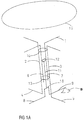
- FIG 1a a table 1, in particular a bistro table with four feet 4, 5, 8, 9, is shown schematically.
- the table 1 is exaggeratedly crooked in order to illustrate the disadvantageous influence of an unevenness in the floor B on which the foot 9 of the table 1 stands.
- Figure 1a shows the table 1 with two laterally foldable legs 2, 3 and their feet 4, 5, as well as with two diagonally opposite rigid legs 6, 7, to which the vertically movable feet 8, 9 separated therefrom are assigned, which are attached to a spar 10 are attached, to which a vertical shaft 11 is attached with a guide 12 attached above, which is arranged between the legs 6, 7.
- Feet 8, 9, spar 10, shaft 11 and guide 12 are connected to form an assembly that can move up and down together.
- Holders 13, 14 are also shown, which connect the laterally foldable legs 2, 3 to the rigid legs 6, 7.
- the brackets 13, 14 allow the legs 2, 3 to be folded sideways for transport purposes so that their feet 4, 5 rest approximately parallel on the vertically movable feet 8, 9 instead of protruding cross-shaped and bulky from them.
- This folding mechanism has long been standard for tables of this type in order to achieve compact dimensions during transport.
- Guide 12 allows the bar 10 to slide vertically between the legs 6, 7 as soon as uneven ground when setting up the table 1 requires that the bar 10 and the feet 8, 9 attached to it move either up or down together in order to achieve that all four feet 4, 5, 8, 9 have contact with the ground at the same time.
- a table top 15 is located on a supporting frame of table 1, which mainly comprises legs 2, 3, 6, 7 and the associated feet 4, 5, 8, 9.
- Figure 1a shows the table 1 in a shaky position on uneven ground.
- the table top 15 of table 1 together with the entire table underframe, would tilt either towards the foot 5 or towards the foot 4 because of the uneven floor B under foot 9.
- the table 1 would be inclined relatively sharply towards the foot 8.
- Figure 1b shows the table 1 after the unevenness of the floor B under foot 9 has been leveled out in a wobble-free setup, which was caused by vertical movement of the assembly consisting of feet 8, 9, spar 10, shaft 11 and guide 12, recognizable in FIG Figure 1b that the distance between guide 12 and bracket 14 is smaller than in Figure 1a .
- the legs 2, 3, 6 and 7 are not exactly vertical, but still inclined relatively slightly to the left in front of the foot 8, but the inclination of the legs 2, 3, 6 and 7 is only half as strong as in this state , the Figure 1a shows.
- the plate 15 of table 1 is not aligned exactly horizontally but also - like the legs 2, 3, 6 and 7 - slightly inclined towards the foot 8, but only half as much as in FIG Figure 1a shown.
- the compensation of the unevenness of the floor B under foot 9 by the mechanism according to the invention of the table 1 not only has the effect that its wobbly installation is ended, but also that its table top 15 is inclined 50% less obliquely than when using the previous makeshift aids, e.g. beer mats or wedges.
- table 1 no longer wobbles back and forth after compensating for the unevenness in the floor B under foot 9, but only stands slightly inclined in the manner described, this slight inclination of table top 15 of table 1 is acceptable because it is hardly noticeable and mostly only below the order of magnitude of the slope, which sidewalks or terraces as typical parking areas of table 1 for the purpose of rainwater runoff usually have anyway and is about 2%, and which causes a corresponding slight inclination of the table top 15, even if in these cases the levels of Footprint of the table 1 and the table top 15 are completely parallel.
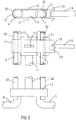
- FIG Figure 2a shows details of a clamping device of the table 1.
- FIG Figure 2a in an enlargement of the shaft 11 attached to the spar 10 with the guide 12 attached to the top, a pin 16 protruding therefrom on both sides, a band 17 with bolts 18 and, in an exemplary embodiment, a manually operated clamping lever 19 with an eccentric bead 20 and an intermediate piece 21 located between the clamping lever 19 and the leg 7, on which the eccentric bead 20 can slide and on which the clamping lever 19 exerts pressure when it is folded down to fix the feet 8, 9 .
- the guide 12 and / or the intermediate piece 21 can have fillets which can be designed to match a cylindrical cross section of the legs 6, 7.
- a correspondingly different shape of the guide 12 and / or the intermediate piece 21 can be provided in order to engage the legs 6, 7 as well as possible.
- the pin 16 attaches the guide 12 to the belt 17 so that they can move together in the vertical direction, but limited independent movement in the horizontal direction is possible.
- at least one elongated hole, preferably two elongated holes, is provided in the band 17 for receiving the pin 16.
- a table 1 compensating for unevenness in the floor B is designed with a clamping lever 19 and an eccentric bead 20.
- a clamping mechanism can also be provided, for example a manually operated rotary knob, a clamping wedge or another mechanism which is suitable for tensioning the band 17 around the legs 6 and 7.
- Figure 2a shows the clamping device of the table 1 before or during the leveling of the unevenness in the floor B under foot 9:
- the eccentric bead 20 on the clamping lever 19 is rotated in such a way that it does not exert any tension on the bolt 18 and belt 17, so that the belt 17 lies loosely around the legs 6 and 7.
- Guide 12, shaft 11, spar 10 and the movable feet 8 and 9 can make a vertical compensation movement upwards or downwards, depending on which type of movement is advantageous through the floor relief when setting up the table 1 on its surface.
- Figure 2b shows the clamping device after completion of the equalization of the unevenness of the ground B under foot 9 in the state of the feet 8, 9 being fixed.
- feet 8, 9, spar 10, shaft 11 and guide 12 have slid upwards on legs 6, 7 to level out any raised unevenness in the floor.
- the eccentric bead 20 is rotated by the downward movement of the clamping lever 19 so that it pulls on the bolt 18 and tightens the band 17 around the legs 6, 7, so that the guide 12, shaft 11, spar 10 and feet 8, 9 can no longer move vertically and table 1 can no longer wobble during use.
- the arrows in Figure 2b left and right of band 17 symbolize the direction in which tension is exerted on band 17 by clamping lever 19.
- All parts or a number of the parts of the underframe of table 1, that is to say all parts below the table top 15, can be made of metal, for example steel.
- Spar 10, guide 12, clamping lever 19 and intermediate piece 21 can also be made of hard plastic.
- Guide 12 and intermediate piece 21 can have horizontal depressions through which the belt 17 is guided in order to always hold these three components together.
- Figure 3 shows schematically details of a further embodiment of the table 1.
- the underframe be provided.
- This can be designed in such a way that a tube half-shell 22 directed vertically upwards is arranged on each of the two movable feet 8, 9, for example each rigidly attached by welding.
- Both pipe half-shells 22 are, for example, on the outside, that is to say on sides of the rigid legs 6, 7 facing away from one another, on the rigid legs 6, 7 of the underframe.
- the pipe half-shells 22 can rest at another point, for example on the inside of the rigid legs 6, 7.
- An inner diameter of the pipe half-shells 22 can be selected to be slightly larger than an outer diameter of the rigid legs 6, 7.
- the task of these pipe half-shells 22 is to suppress sideways oscillating oscillating movements of the underframe on its upper part.
- the pipe half-shells 22 do not rub against the legs 6, 7, which are on their insides, they can carry thin half-shells made of slidable plastic on the inside or be provided with a coating, for example made of slidable plastic.
- the upper ends of the pipe half-shells can be included in the clamping device in such a way that they protrude into the clamping device from below and are clamped by these on the rigid legs 6, 7 on the inside of the pipe half-shells 22.
Landscapes
- Tables And Desks Characterized By Structural Shape (AREA)
- Accommodation For Nursing Or Treatment Tables (AREA)
Description
- Die vorliegende Erfindung betrifft einen einstellbaren Tisch, insbesondere einen vierfüßigen Tisch.
- Tische, insbesondere vierfüßige Tische, beispielsweise die weit verbreiteten und einen eigenen Standard darstellenden transportablen Bistro-Tische mit vier gebogenen Stahlrohr-Beinen, von denen zwei seitlich klappbar sind, mit ebenfalls klappbaren, meist runden Tischplatten von beispielsweise 80 cm Durchmesser und mit Tisch-Höhen von ca. 70 cm und ca. 110 cm, werden häufig an einem anderen Standort mit jeweils anderem Bodenrelief aufgestellt und wackeln fast immer auf nahezu jedem Untergrund, wenn dieser auch nur geringe Unebenheiten hat, weil dann eines der vier Beine keinen Bodenkontakt hat, mit der Folge, dass der Tisch bei Gebrauch nahezu jedes Mal heftig ruckartig wackelt und dabei Getränke überschwappen lässt oder die Einnahme von Mahlzeiten zu einem ärgerlichen Balance-Akt geraten lässt.
- Die üblichen Gegenmaßnahmen, beispielsweise Unterlegen kleiner Gegenstände oder Verstellen von Ausgleichs-Schrauben an einem Tisch-Fuß, sind meist unzureichend, unzumutbar wegen Schmutz an den Tisch-Füßen oder sind mangels Material unmöglich, auf jeden Fall aber sind sie lästig und unterbleiben vielfach aus mindestens einem dieser Gründe.
- Wirte, Kellner und Gäste sind weltweit täglich mit diesem Problem konfrontiert.
- Insbesondere für vollständig klappbare, mobile Tische existiert bisher keine zufriedenstellende Lösung des Wackel-Problems.
- Die
WO 2006/101279 A1 offenbart einen Tisch, bei dem die Höhe einer Oberseite eines Tisches gemäß der Größe eines Benutzers eingestellt werden kann, um den Komfort des Benutzers zu verbessern. Der Tisch umfasst ein erstes Bein, das mit einer Oberseite eines Tisches verbunden ist, und ein zweites Bein zum Tragen der horizontal zu haltenden Oberseite, wobei das zweite Bein mit dem ersten Bein verbunden ist und in Längsrichtung ausziehbar und zusammenziehbar ist. Ein Verriegelungsabschnitt ist entweder am ersten Bein oder am zweiten Bein vorgesehen, um den Beinabschnitt mittels eines Betätigungshebels zu verriegeln und freizugeben. Mit dieser Struktur kann der Tisch für verschiedene Größen von Benutzern zu Hause, in Büros oder in Schulen verwendet werden. - Es ist eine Aufgabe der vorliegenden Erfindung, einen verbesserten einstellbaren Tisch anzugeben.
- Die Aufgabe wird gelöst durch einen Tisch mit den Merkmalen des Anspruchs 1.
- Vorteilhafte Weiterbildungen sind Gegenstand der abhängigen Ansprüche.
- Ein erfindungsgemäßer Tisch umfasst eine Tischplatte und ein Untergestell, umfassend ein erstes Paar Beine mit jeweils zugeordneten Füßen und ein zweites Paar Beine mit jeweils zugeordneten Füßen, wobei die Füße des ersten Paars einen festen Abstand zur Tischplatte aufweisen, wobei die Füße des zweiten Paars untereinander verbunden und gemeinsam hinsichtlich ihres Abstands zur Tischplatte verstellbar sind, insbesondere durch Verschieben und insbesondere so, dass beide Füße des zweiten Paars den gleichen Abstand zur Tischplatte aufweisen, wobei eine Klemmvorrichtung vorgesehen ist, mittels derer die Füße des zweiten Paars in ihrem Abstand zur Tischplatte arretierbar sind.
- Erfindungsgemäß sind die Füße des zweiten Paars durch einen Holm untereinander verbunden, der an einem Schaft befestigt ist, der mittels einer Führung zwischen den Beinen eines der Paare, beispielsweise des ersten oder des zweiten Paars, führbar ist.
- Erfindungsgemäß umfasst die Klemmvorrichtung ein spannbares Band, mittels dessen die am Schaft befestigte Führung zwischen den Beinen eines der Paare festklemmbar ist, wenn das Band gespannt ist, wobei die Führung entlang der Beine dieses Paares beweglich ist, wenn das Band entspannt ist.
- In einer Ausführungsform der Erfindung ist ein Klemm-Hebel mit einem Exzenter-Wulst zum Spannen des Bandes angeordnet. Alternativ kann aber auch eine andere Art von Klemm-Mechanismus vorgesehen sein, beispielsweise ein manuell zu bedienender Dreh-Knauf, ein Klemm-Keil oder ein anderer Mechanismus, welcher geeignet ist, das Band um die Beine und zu spannen.
- In einer Ausführungsform der Erfindung ist ein Zwischenstück zwischen einem der Beine und dem Klemm-Hebel zur Abstützung des Exzenter-Wulsts vorgesehen.
- In einer Ausführungsform der Erfindung ist die Führung mittels eines Stifts in mindestens einem im Band angeordneten Langloch gehalten. Alternativ zum Langloch kann auch ein Rundloch vorgesehen sein, das einen Durchmesser aufweist, der größer ist als der Durchmesser des Stifts.
- In einer Ausführungsform der Erfindung liegen die Beine des ersten Paars einander diagonal gegenüber, wobei die Beine des zweiten Paars einander diagonal gegenüber liegen.
- In einer Ausführungsform der Erfindung sind die Beine des ersten Paars um eine vertikale Achse schwenkbar.
- In einer Ausführungsform der Erfindung sind die Beine des zweiten Paars starr mit der Tischplatte verbunden.
- In einer Ausführungsform der Erfindung sind eine oder mehrere Halterungen vorgesehen, welche die Beine des ersten Paars mit den Beinen des zweiten Paars verbinden.
- In einer Ausführungsform sind die Beine des zweiten Paars starr mit der Tischplatte verbunden, wobei den Beinen des zweiten Paars die davon getrennten vertikal beweglichen Füße zugeordnet sind.
- In einer Ausführungsform ist an mindestens einem der vertikal beweglichen Füße eine Rohr-Halbschale derart fest angebracht, insbesondere angeschweißt, dass die Rohr-Halbschale an einem der starren Beine verschiebbar anliegt. Insbesondere ist an jedem der vertikal beweglichen Füße je eine Rohr-Halbschale derart fest angebracht, insbesondere angeschweißt, dass die Rohr-Halbschale an je einem der starren Beine verschiebbar anliegt.
- In einer Ausführungsform weist die Rohr-Halbschale einen konkaven Bereich zur Aufnahme eines Bereiches eines der starren Beine auf. Insbesondere korrespondiert die Form des konkaven Bereichs der Rohr-Halbschale mit einer Form des starren Beins auf dessen Außenseite. Beispielsweise kann das starre Bein die Form eines Kreiszylinders und die Rohr-Halbschale dementsprechend die Form eines längs halbierten Kreiszylinders aufweisen.
- In einer Ausführungsform ist ein Innendurchmesser der Rohr-Halbschale geringfügig größer als ein Außendurchmesser des daran anliegenden der starren Beine.
- In einer Ausführungsform ist zwischen der Rohr-Halbschale und dem daran anliegenden der starren Beine eine Schicht aus gleitfähigem Kunststoff vorgesehen. Die Schicht kann beispielsweise als Halbschale im konkaven Bereich der Rohr-Halbschale oder als Beschichtung des starren Beins ausgebildet sein.
- In einer Ausführungsform ragt die Rohr-Halbschale in die Klemmvorrichtung hinein und ist durch diese an dem daran anliegenden der starren Beine arretierbar.
- Mittels der erfindungsgemäßen Lösung wird das Problem wackelnder Tische, insbesondere vierfüßiger Tische gelöst, durch Ausgleich von Niveau-Unterschieden des Tisch-Untergrunds, insbesondere schon beim Aufstellen des Tischs, mittels zweier diagonal gegenüberliegender gemeinsam auf und ab beweglicher Füße, die abschließend mechanisch fixiert werden, beispielsweise manuell.
- Die zwei beweglichen Füße, horizontal durch einen Holm verbunden, werden je nach Unebenheit des Tisch-Untergrundes zwecks Niveau-Ausgleich mittels eines vertikalen Schafts auf- oder abwärts geführt, dessen oberes Ende in der Position befestigt wird, die er nach erfolgtem Niveau-Ausgleich einnimmt, beispielsweise durch einen Klemm-Mechanismus.
- Der Klemm-Mechanismus arretiert die beweglichen Füße durch Kraftschluss zwischen dem vertikalen Schaft und den unbeweglichen Tisch-Beinen. Die beweglichen Füße sind von den unbeweglichen Tischbeinen getrennt und bilden mit Holm und Schaft eine auf und ab bewegliche Baugruppe für den Niveau-Ausgleich.
- Der erfindungsgemäße Tisch erfreut Wirte, Kellner und Gäste, indem er Schluss macht mit lästigen Wackeleien von Tischen, die bisher zu vielerlei Verdruss Anlass gaben.
- Die vorliegende Erfindung gibt ihren Anwendern Gelegenheit, transportable, vollständig klappbare Tische bereits während des Aufstellens Boden-Unebenheiten ausgleichen zu lassen, bis diese Tische eine wackelfreie Position eingenommen haben, um sie dann mit einer Handbewegung in dieser Position zu fixieren.
- Die der vorliegenden Erfindung gemäße Lösung ist preisgünstig, zuverlässig und sieht gut aus. Die vorliegende Erfindung ist nützlich, denn sie ermöglicht erstmals, Tische, insbesondere mobile Tische, deren Standort häufig wechselt, schnell und bequem wackelfrei aufzustellen, ohne zeitraubende unangenehme Verrenkungen der Nutzer, beispielsweise Wirte, Kellner oder Gäste.
- Im Folgenden werden Ausführungsbeispiele der Erfindung anhand von Abbildungen erläutert. Dabei zeigen:
- Figur 1a
- eine schematische Abbildung eines einstellbaren Tisches,
- Figur 1b
- eine schematische Abbildung des einstellbaren Tisches nach einer Höhenverstellung zweier einstellbarer Tischbeine,
- Figur 2a
- schematische Ansichten einer Klemmvorrichtung in einer Verstellposition,
- Figur 2b
- schematische Ansichten der Klemmvorrichtung in einer Klemmposition, und
- Figur 3
- schematische Detailansichten einer weiteren Ausgestaltung des Tischs.
- Einander entsprechende Merkmale sind in allen Figuren durch gleiche Bezugszeichen gekennzeichnet.
- Lage- und Orientierungsangaben sind auf eine Gebrauchslage des Tisches bezogen.
- In
Figur 1a ist schematisch ein Tisch 1, insbesondere ein Bistro-Tisch mit vier Füßen 4, 5, 8, 9, dargestellt. In der Abbildung steht der Tisch 1 übertrieben schief um den nachteiligen Einfluss einer Boden-Unebenheit B, auf dem der Fuß 9 des Tischs 1 steht, zu verdeutlichen.Figur 1a zeigt den Tisch 1 mit zwei seitlich klappbaren Beinen 2, 3 und deren Füßen 4, 5, sowie mit zwei diagonal einander gegenüber befindlichen starren Beinen 6, 7, denen die davon getrennten vertikal beweglichen Füße 8, 9 zugeordnet sind, welche an einem Holm 10 befestigt sind, an welchem ein vertikaler Schaft 11 befestigt ist mit einer oben angebrachten Führung 12, die zwischen den Beinen 6, 7 angeordnet ist. - Füße 8, 9, Holm 10, Schaft 11 und Führung 12 sind verbunden zu einer gemeinsam auf und ab beweglichen Baugruppe.
- Weiter sind Halterungen 13, 14 dargestellt, welche die seitlich klappbaren Beine 2, 3 mit den starren Beinen 6, 7 verbinden. Die Halterungen 13, 14 gestatten, für Transportzwecke die Beine 2, 3 seitlich so zu klappen, dass deren Füße 4, 5 an den vertikal beweglichen Füßen 8, 9 etwa parallel anliegen, statt quer und sperrig von diesen kreuzförmig abzustehen. Diese Klapp-Mechanik ist seit langem Standard bei Tischen dieser Art, um kompakte Abmessungen beim Transport zu erzielen.
- Führung 12 lässt den Holm 10 vertikal zwischen den Beinen 6, 7 gleiten, sobald unebener Untergrund beim Aufstellen des Tischs 1 erfordert, dass Holm 10 und die daran befestigten Füße 8, 9 sich entweder gemeinsam aufwärts oder abwärts bewegen, um zu erreichen, dass alle vier Füße 4, 5, 8, 9 gleichzeitig Bodenkontakt haben.
- Auf einem tragenden Gestell von Tisch 1, welches hauptsächlich die Beine 2, 3, 6, 7 und die zugehörigen Füßen 4, 5, 8, 9 umfasst, befindet sich eine Tischplatte 15.
-
Figur 1a zeigt den Tisch 1 in wackeliger Aufstellung auf unebenem Boden. Die Tischplatte 15 von Tisch 1 würde zusammen mit dem gesamten Tisch-Untergestell wegen der Boden-Unebenheit B unter Fuß 9 entweder zum Fuß 5 oder zum Fuß 4 hin kippen. Außerdem wäre der Tisch 1 relativ stark zum Fuß 8 hin geneigt. -
Figur 1b zeigt den Tisch 1 nach erfolgtem Ausgleich der Boden-Unebenheit B unter Fuß 9 in wackelfreier Aufstellung, welche durch vertikale Bewegung der aus Füßen 8, 9, Holm 10, Schaft 11 und Führung 12 bestehenden Baugruppe bewirkt wurde, erkennbar inFigur 1b daran, dass der Abstand zwischen Führung 12 und Halterung 14 kleiner ist als inFigur 1a . - Die Beine 2, 3, 6 und 7 stehen nicht exakt senkrecht, sondern immer noch relativ leicht nach links vorn zum Fuß 8 hin geneigt, jedoch ist die Neigung der Beine 2, 3, 6 und 7 nur noch halb so stark wie in dem Zustand, den
Figur 1a zeigt. - Entsprechend ist die Platte 15 von Tisch 1 nicht exakt horizontal ausgerichtet sondern ebenfalls, - wie die Beine 2, 3, 6 und 7, leicht zum Fuß 8 hin geneigt, jedoch nur halb so stark wie in
Figur 1a dargestellt. - Die in
Figur 1a gezeigte relativ starke Schief-Stellung von Tisch 1 zum Fuß 8 hin wäre auf nachteilige Weise unverändert geblieben, falls wie herkömmlich Bierdeckel oder Keile oder ähnliche Gegenstände unter einem der Füße 4, 5 angebracht worden wären. - Der Ausgleich der Boden-Unebenheit B unter Fuß 9 durch die erfindungsgemäße Mechanik des Tischs 1 bewirkt also nicht nur, dass seine wackelige Aufstellung beendet ist, sondern auch, dass seine Tischplatte 15 um 50 % weniger schief geneigt ist als bei Verwendung der bisherigen Notbehelfe, z.B. Bierdeckel oder Keile.
- Solange Tisch 1 nach erfolgtem Ausgleich der Boden-Unebenheit B unter Fuß 9 nicht mehr hin und her wackelt, sondern nur in der beschriebenen Weise leicht schräg steht, ist diese geringe Neigung der Tischplatte 15 von Tisch 1 hinnehmbar, da sie kaum auffällt und meist lediglich unterhalb der Größenordnung des Gefälles, welches Trottoirs oder Terrassen als typische Stellflächen von Tisch 1 zwecks Regenwasser-Ablaufs ohnehin meist aufweisen und etwa 2 % beträgt, und welches eine entsprechende leichte Schräg-Stellung der Tischplatte 15 bewirkt, selbst wenn in diesen Fällen die Ebenen von Stellfläche des Tischs 1 und der Tischplatte 15 völlig parallel sind.
- Keineswegs besteht erhöhte Gefahr, dass Gegenstände von der Tischplatte 15 rollen, sogar falls ein unachtsamer Nutzer kugelförmige oder zylindrische Gegenstände auf die Platte 15 legt. Selbst wenn kugelförmige oder zylindrische Gegenstände auf der Tischplatte 15 liegen würden, wäre durch die erfindungsgemäße Vorrichtung die Schrägstellung der Tischplatte 15 um 50 % gemindert gegenüber der herkömmlichen Bauweise und auf diese Weise würde ein Wegrollen kugelförmiger oder zylindrischer Gegenstände nur noch halb so heftig auftreten und nur noch halb so wahrscheinlich vorkommen wie bei herkömmlicher Bauweise.
-
Figur 2a zeigt Einzelheiten einer Klemmvorrichtung des Tischs 1. Zunächst zeigtFigur 2a in Vergrößerung den am Holm 10 befestigten Schaft 11 mit der oben daran angebrachten Führung 12, einen beiderseits daraus hervor ragenden Stift 16, ein Band 17 mit Bolzen 18 sowie in einer beispielhaften Ausführung einen manuell zu betätigenden Klemm-Hebel 19 mit Exzenter-Wulst 20 und ein zwischen dem Klemm-Hebel 19 und dem Bein 7 befindliches Zwischenstück 21, auf welchem der Exzenter-Wulst 20 gleiten kann und auf welches der Klemm-Hebel 19 Druck ausübt, wenn er nach unten umgelegt ist, um die Füße 8, 9 zu fixieren. Die Führung 12 und/oder das Zwischenstück 21 können Hohlkehlen aufweisen, die passend zu einem zylindrischen Querschnitt der Beine 6, 7 ausgebildet sein können. Bei einer anderen Querschnittsform der Beine 6, 7 kann eine entsprechend andere Form der Führung 12 und/oder des Zwischenstücks 21 vorgesehen sein, um die Beine 6, 7 möglichst gut in Eingriff zu nehmen. Der Stift 16 befestigt die Führung 12 am Band 17 so, dass sich diese gemeinsam in vertikaler Richtung bewegen können, jedoch eine beschränkte unabhängige Bewegung in horizontaler Richtung möglich ist. Hierzu ist im Band 17 beispielsweise mindestens ein Langloch, vorzugsweise zwei Langlöcher, zur Aufnahme des Stifts 16 vorgesehen. - In der dargestellten Ausführungsform ist die erfindungsgemäße Vorrichtung, ein Boden-Unebenheiten B ausgleichender Tisch 1, mit Klemm-Hebel 19 und Exzenter-Wulst 20 ausgestaltet. Alternativ kann aber auch eine andere Art von Klemm-Mechanismus vorgesehen sein, beispielsweise ein manuell zu bedienender Dreh-Knauf, ein Klemm-Keil oder ein anderer Mechanismus, welcher geeignet ist, das Band 17 um die Beine 6 und 7 zu spannen.
-
Figur 2a zeigt die Klemmvorrichtung des Tischs 1 vor oder während des Ausgleichs der Boden-Unebenheit B unter Fuß 9:
Der Exzenter-Wulst 20 am Klemm-Hebel 19 ist so gedreht, dass er keinen Zug auf Bolzen 18 und Band 17 ausübt, so dass Band 17 lose um die Beine 6 und 7 liegt. Führung 12, Schaft 11, Holm 10 und die beweglichen Füße 8 und 9 können eine vertikale Ausgleichs-Bewegung aufwärts oder abwärts vornehmen, je nachdem, welche Art der Bewegung durch das Boden-Relief beim Aufstellen des Tischs 1 auf seinem Untergrund vorteilhaft ist. -
Figur 2b zeigt die Klemmvorrichtung nach Beendigung des Ausgleichs der Boden-Unebenheit B unter Fuß 9 im Zustand der Fixierung der Füße 8, 9. Im dargestellten Fall sind Füße 8, 9, Holm 10, Schaft 11 und Führung 12 an den Beinen 6, 7 aufwärts geglitten, um eine erhabene Boden-Unebenheit auszugleichen. Der Exzenter-Wulst 20 ist durch Abwärts-Bewegung des KlemmHebels 19 so gedreht, dass er am Bolzen 18 zieht und das Band 17 fest um die Beine 6, 7 spannt, so dass Führung 12, Schaft 11, Holm 10 und Füße 8, 9 sich vertikal nicht mehr bewegen können und Tisch 1 bei Gebrauch nicht mehr wackeln kann. Die Pfeile inFigur 2b links und rechts von Band 17 symbolisieren die Richtung, in welcher durch den Klemm-Hebel 19 Zug ausgeübt wird auf das Band 17. - Alle Teile oder eine Anzahl der Teile des Untergestells von Tisch 1, das heißt alle Teile unterhalb der Tischplatte 15, können aus Metall, beispielsweise aus Stahl, hergestellt sein. Holm 10, Führung 12, Klemm-Hebel 19 und Zwischenstück 21, können auch aus Hartplastik gebildet sein.
- Führung 12 und Zwischenstück 21 können horizontale Vertiefungen aufweisen, durch welche das Band 17 geführt wird, um diese drei Bauteile stets zusammenzuhalten.
-
Figur 3 zeigt schematisch Details einer weiteren Ausgestaltung des Tischs 1. - Zur seitlichen Stabilisierung des aus den Beinen 2, 3, 6, 7 und Füßen 4, 5, 8, 9 gebildeten Untergestells des Tischs, um Hin- und Her-Schwingen der Tischplatte 15, beispielsweise in Längsrichtung der Klemmvorrichtung zu verhindern, kann eine Aussteifung des Untergestells vorgesehen sein. Diese kann so beschaffen sein, dass an den beiden beweglichen Füßen 8, 9 jeweils eine senkrecht nach oben gerichtete Rohr-Halbschale 22 angeordnet ist, beispielsweise jeweils starr angebracht durch Schweißen. Beide Rohr-Halbschalen 22 liegen beispielsweise außen, das heißt auf voneinander abgewandten Seiten der starren Beine 6, 7, an den starren Beinen 6, 7 des Untergestells an. In einer anderen Ausführungsform können die Rohr-Halbschalen 22 an einer anderen Stelle, beispielsweise innen an den starren Beinen 6, 7 anliegen.
- Ein Innendurchmesser der Rohr-Halbschalen 22 kann geringfügig größer gewählt sein als ein Außendurchmesser der starren Beine 6, 7.
- Aufgabe dieser Rohr-Halbschalen 22 ist, seitlich pendelnde Schwing-Bewegungen des Untergestells an dessen oberem Teil zu unterdrücken.
- Damit die Rohr-Halbschalen 22 nicht an den Beinen 6, 7, welche an ihren Innenseiten liegen, scheuern, können sie dünne Halbschalen aus gleitfähigem Kunststoff auf der Innenseite tragen oder mit einer Beschichtung, beispielsweise aus gleitfähigem Kunststoff, versehen sein.
- Damit die Rohr-Halbschalen 22 sich starr verhalten und so den Tisch stabilisieren sobald der Tisch 1 durch den Klemmhebel 19 verriegelt wird, können die oberen Enden der Rohr-Halbschalen in die Klemmvorrichtung einbezogen sein, derart, dass sie von unten in die Klemmvorrichtung hineinragen und durch diese an den starren Beinen 6, 7 auf der Innenseite der Rohr-Halbschalen 22 festgeklemmt werden.
- Anstelle der Rohr-Halbschalen 22 kann auch je ein längliches Bauteil mit einem anderen Profil verwendet werden, die an den starren beinen 6, 7 anliegt und beispielsweise in die Klemmvorrichtung hinein geführt ist.
-
- 1
- Tisch
- 2
- seitlich klappbares Bein
- 3
- seitlich klappbares Bein
- 4
- Fuß
- 5
- Fuß
- 6
- starres Bein
- 7
- starres Bein
- 8
- beweglicher Fuß
- 9
- beweglicher Fuß
- 10
- Holm
- 11
- Schaft
- 12
- Führung
- 13
- Halterung
- 14
- Halterung
- 15
- Tischplatte
- 16
- Stift
- 17
- Band
- 18
- Bolzen
- 19
- Klemm-Hebel
- 20
- Exzenter-Wulst
- 21
- Zwischenstück
- 22
- Rohr-Halbschalen
- B
- Boden-Unebenheit
Claims (13)
- Tisch (1), umfassend eine Tischplatte (15) und ein Untergestell, umfassend ein erstes Paar Beine (2, 3) mit jeweils zugeordneten Füßen (4, 5) und ein zweites Paar Beine (6, 7) mit jeweils zugeordneten Füßen (8, 9), wobei die Füße (4, 5) des ersten Paars einen festen Abstand zur Tischplatte (15) aufweisen, wobei die Füße (8, 9) des zweiten Paars untereinander verbunden und gemeinsam hinsichtlich ihres Abstands zur Tischplatte (15) verstellbar sind, wobei eine Klemmvorrichtung vorgesehen ist, mittels derer die Füße (8, 9) des zweiten Paars in ihrem Abstand zur Tischplatte (15) arretierbar sind, wobei die Füße (8, 9) des zweiten Paars durch einen Holm (10) untereinander verbunden sind, der an einem Schaft (11) befestigt ist, der mittels einer Führung (12) zwischen den Beinen (2, 3, 6, 7) eines der Paare führbar ist, dadurch gekennzeichnet, dass die Klemmvorrichtung ein spannbares Band (17) umfasst, mittels dessen die am Schaft befestigte Führung (12) zwischen den Beinen (2, 3, 6, 7) eines der Paare festklemmbar ist, wenn das Band gespannt ist, wobei die Führung (12) entlang der Beine (2, 3, 6, 7) dieses Paars beweglich ist, wenn das Band (17) entspannt ist.
- Tisch (1) nach Anspruch 1, wobei ein Klemm-Hebel (19) mit einem Exzenter-Wulst (20) oder ein Dreh-Knauf oder ein Klemm-Keil zum Spannen des Bandes (17) angeordnet ist.
- Tisch (1) nach Anspruch 2, wobei ein Zwischenstück (21) zwischen einem der Beine (2, 3, 6, 7) und dem Klemm-Hebel (19) zur Abstützung des Exzenter-Wulsts (20) vorgesehen ist.
- Tisch (1) nach einem der Ansprüche 1 bis 3, wobei die Führung (12) mittels eines Stifts (16) in mindestens einem im Band (17) angeordneten Langloch oder Rundloch gehalten ist.
- Tisch (1) nach einem der vorhergehenden Ansprüche, wobei die Beine (2, 3) des ersten Paars einander diagonal gegenüberliegen und wobei die Beine (6, 7) des zweiten Paars einander diagonal gegenüberliegen.
- Tisch (1) nach einem der vorhergehenden Ansprüche, wobei die Beine (2, 3) des ersten Paars um eine vertikale Achse schwenkbar sind.
- Tisch (1) nach einem der vorhergehenden Ansprüche, wobei die Beine (6, 7) des zweiten Paars starr mit der Tischplatte (15) verbunden sind.
- Tisch (1) nach einem der vorhergehenden Ansprüche, wobei eine oder mehrere Halterungen (13, 14) vorgesehen sind, welche die Beine (2, 3) des ersten Paars mit den Beinen (6, 7) des zweiten Paars verbinden.
- Tisch (1) nach einem der vorhergehenden Ansprüche, wobei die Beine (6,7) des zweiten Paars starr mit der Tischplatte (15) verbunden sind, denen die davon getrennten vertikal beweglichen Füße (8, 9) zugeordnet sind.
- Tisch (1) nach einem der vorhergehenden Ansprüche, wobei an mindestens einem der vertikal beweglichen Füße (8, 9) eine Rohr-Halbschale (22) derart fest angebracht ist, dass die Rohr-Halbschale (22) an einem der starren Beine (6, 7) verschiebbar anliegt.
- Tisch (1) nach Anspruch 10, wobei die Rohr-Halbschale (22) einen konkaven Bereich zur Aufnahme eines Bereiches eines der starren Beine (6, 7) aufweist.
- Tisch (1) nach einem der Ansprüche 10 oder 11, wobei zwischen der Rohr-Halbschale (22) und dem daran anliegenden der starren Beine (6, 7) eine Schicht aus gleitfähigem Kunststoff vorgesehen ist.
- Tisch (1) nach einem der Ansprüche 10 bis 12, wobei die Rohr-Halbschale (22) in die Klemmvorrichtung hineinragt und durch diese an dem daran anliegenden der starren Beine (6, 7) arretierbar ist.
Applications Claiming Priority (1)
| Application Number | Priority Date | Filing Date | Title |
|---|---|---|---|
| DE102018203414.1A DE102018203414B3 (de) | 2018-03-07 | 2018-03-07 | Einstellbarer Tisch |
Publications (2)
| Publication Number | Publication Date |
|---|---|
| EP3536191A1 EP3536191A1 (de) | 2019-09-11 |
| EP3536191B1 true EP3536191B1 (de) | 2021-07-14 |
Family
ID=65724232
Family Applications (1)
| Application Number | Title | Priority Date | Filing Date |
|---|---|---|---|
| EP19161212.6A Active EP3536191B1 (de) | 2018-03-07 | 2019-03-07 | Einstellbarer tisch |
Country Status (2)
| Country | Link |
|---|---|
| EP (1) | EP3536191B1 (de) |
| DE (1) | DE102018203414B3 (de) |
Families Citing this family (2)
| Publication number | Priority date | Publication date | Assignee | Title |
|---|---|---|---|---|
| EP4719132A1 (de) * | 2023-05-30 | 2026-04-08 | Ilse, Hansjorg | Selbststabilisierender sockel |
| US12096853B1 (en) | 2023-12-20 | 2024-09-24 | David Hastings Bahnson | Stabilizing a table |
Family Cites Families (9)
| Publication number | Priority date | Publication date | Assignee | Title |
|---|---|---|---|---|
| US2513889A (en) | 1945-07-02 | 1950-07-04 | Becker Wilhelm Ab | Device in easels for locking the parts of the displaceable legs to one another |
| DE4106648C2 (de) | 1991-03-02 | 1994-04-07 | Herbert Gruettner Gmbh & Co Kg | Klapptisch und Klappfußgelenk |
| EP0910260B1 (de) | 1996-05-31 | 2002-10-09 | Shiranor Investments Limited | Stabilisierungseinrichtung |
| DE10118533A1 (de) * | 2001-04-05 | 2002-10-17 | Reiss Bueromoebel Gmbh | Einrichtung zur feststellbaren Längenveränderung zweier rohrförmiger Körper |
| DE20314333U1 (de) * | 2003-09-16 | 2003-12-11 | Van Schoor, Berthold | Höhenverstellbares Tischgestell, vorzugsweise für runde und quadratische Tischplattenformen mit vertikalen, zentral angeordneten, gebündelten geraden Profilen |
| FR2873003B1 (fr) | 2004-07-13 | 2006-09-22 | Inter Company Comp Engineering | Mobilier de bureau comprenant des pietements a configuration multiple |
| WO2006101279A1 (en) * | 2005-03-19 | 2006-09-28 | Duoback Korea Co., Ltd. | Adjustable height device for the leg of a table |
| WO2016133744A1 (en) | 2015-02-17 | 2016-08-25 | Rafii Eddie | Table and chair with self-stablizing system |
| DE102016005267A1 (de) * | 2015-05-02 | 2016-11-03 | Richard Gerhold | Selbst nivellierendes klappfähiges wackelfreies Tisch-Untergestell mit vier Beinen |
-
2018
- 2018-03-07 DE DE102018203414.1A patent/DE102018203414B3/de active Active
-
2019
- 2019-03-07 EP EP19161212.6A patent/EP3536191B1/de active Active
Also Published As
| Publication number | Publication date |
|---|---|
| EP3536191A1 (de) | 2019-09-11 |
| DE102018203414B3 (de) | 2019-07-11 |
Similar Documents
| Publication | Publication Date | Title |
|---|---|---|
| EP2539177B1 (de) | Anordnung eines einklappbaren tischs | |
| EP0482333B1 (de) | Tisch mit beweglicher Arbeitsplatte | |
| DE2717331A1 (de) | Stuhl mit verstellbarer rueckenlehne | |
| EP1358821B1 (de) | Stuhl mit vom Benutzergewicht abhängigen Kraftspeicher | |
| DE20118884U1 (de) | Mit Füßen versehene, verschwenkbare Platte | |
| EP2899070B1 (de) | Vorrichtung zur Höhenverstellung eines Ladebodens in einem Fahrzeug | |
| EP0663164B1 (de) | Möbelstück mit einer stationären Platte sowie mit wenigstens zwei Ansetzplatten | |
| WO2014180629A1 (de) | Sitzmöbelstück und beschlag hierfür | |
| DE102021115102A1 (de) | Höhenverstellbarer Tisch | |
| WO2002011954A1 (de) | Traggestell, insbesondere rollenbock | |
| EP3536191A1 (de) | Einstellbarer tisch | |
| DE29715343U1 (de) | Sitzmöbel, insbesondere Gartensessel | |
| EP0274569B1 (de) | Schreibtisch mit einer zusätzlichen Pultplatte | |
| DE8312140U1 (de) | Stehentlastung | |
| DE4120260C1 (en) | Balanced holder for medical appts. component - has swivelable combined arm with component holding and lever arm sections | |
| DE8716122U1 (de) | Vorrichtung zum Verstellen eines an einem Matratzenrahmen angelenkten Kopfteiles | |
| DE4417270A1 (de) | Tisch bzw. Gestell mit wenigstens drei Standbeinen bzw. Standfüßen | |
| DE19511176C2 (de) | Vorrichtung zur Verstellung der Höhe und/oder Neigung der Tischplatte eines Tisches | |
| DE4312501A1 (de) | Arbeitsgestell | |
| EP1976669A1 (de) | Arbeitsbock, insbesondere sägebock, und werktischgestell | |
| EP1106422A1 (de) | Halterung für einen Fahrzeugsitz | |
| DE3111920A1 (de) | Arbeitstisch mit hoehenverstellbarer tischplatte | |
| DE1580609A1 (de) | Sitzgestell,insbesondere fuer Kraftfahrzeuge | |
| DE4429636C1 (de) | Stehentlastung | |
| DE8805510U1 (de) | Sitzschalen-Fahrwerk, insbesondere für Körperbehinderte |
Legal Events
| Date | Code | Title | Description |
|---|---|---|---|
| PUAI | Public reference made under article 153(3) epc to a published international application that has entered the european phase |
Free format text: ORIGINAL CODE: 0009012 |
|
| STAA | Information on the status of an ep patent application or granted ep patent |
Free format text: STATUS: THE APPLICATION HAS BEEN PUBLISHED |
|
| AK | Designated contracting states |
Kind code of ref document: A1 Designated state(s): AL AT BE BG CH CY CZ DE DK EE ES FI FR GB GR HR HU IE IS IT LI LT LU LV MC MK MT NL NO PL PT RO RS SE SI SK SM TR |
|
| AX | Request for extension of the european patent |
Extension state: BA ME |
|
| STAA | Information on the status of an ep patent application or granted ep patent |
Free format text: STATUS: REQUEST FOR EXAMINATION WAS MADE |
|
| 17P | Request for examination filed |
Effective date: 20200220 |
|
| RBV | Designated contracting states (corrected) |
Designated state(s): AL AT BE BG CH CY CZ DE DK EE ES FI FR GB GR HR HU IE IS IT LI LT LU LV MC MK MT NL NO PL PT RO RS SE SI SK SM TR |
|
| REG | Reference to a national code |
Ref country code: DE Ref legal event code: R079 Free format text: PREVIOUS MAIN CLASS: A47B0009080000 Ipc: A47B0091160000 |
|
| GRAP | Despatch of communication of intention to grant a patent |
Free format text: ORIGINAL CODE: EPIDOSNIGR1 |
|
| STAA | Information on the status of an ep patent application or granted ep patent |
Free format text: STATUS: GRANT OF PATENT IS INTENDED |
|
| INTG | Intention to grant announced |
Effective date: 20210211 |
|
| RIC1 | Information provided on ipc code assigned before grant |
Ipc: A47B 91/16 20060101AFI20210201BHEP |
|
| GRAS | Grant fee paid |
Free format text: ORIGINAL CODE: EPIDOSNIGR3 |
|
| GRAA | (expected) grant |
Free format text: ORIGINAL CODE: 0009210 |
|
| STAA | Information on the status of an ep patent application or granted ep patent |
Free format text: STATUS: THE PATENT HAS BEEN GRANTED |
|
| AK | Designated contracting states |
Kind code of ref document: B1 Designated state(s): AL AT BE BG CH CY CZ DK EE ES FI FR GB GR HR HU IE IS IT LI LT LU LV MC MK MT NL NO PL PT RO RS SE SI SK SM TR |
|
| RBV | Designated contracting states (corrected) |
Designated state(s): AL AT BE BG CH CY CZ DK EE ES FI FR GB GR HR HU IE IS IT LI LT LU LV MC MK MT NL NO PL PT RO RS SE SI SK SM TR |
|
| REG | Reference to a national code |
Ref country code: GB Ref legal event code: FG4D Free format text: NOT ENGLISH Ref country code: DE Ref legal event code: R108 |
|
| REG | Reference to a national code |
Ref country code: IE Ref legal event code: FG4D Free format text: LANGUAGE OF EP DOCUMENT: GERMAN |
|
| REG | Reference to a national code |
Ref country code: AT Ref legal event code: REF Ref document number: 1409979 Country of ref document: AT Kind code of ref document: T Effective date: 20210815 |
|
| REG | Reference to a national code |
Ref country code: LT Ref legal event code: MG9D |
|
| REG | Reference to a national code |
Ref country code: NL Ref legal event code: MP Effective date: 20210714 |
|
| PG25 | Lapsed in a contracting state [announced via postgrant information from national office to epo] |
Ref country code: SE Free format text: LAPSE BECAUSE OF FAILURE TO SUBMIT A TRANSLATION OF THE DESCRIPTION OR TO PAY THE FEE WITHIN THE PRESCRIBED TIME-LIMIT Effective date: 20210714 Ref country code: RS Free format text: LAPSE BECAUSE OF FAILURE TO SUBMIT A TRANSLATION OF THE DESCRIPTION OR TO PAY THE FEE WITHIN THE PRESCRIBED TIME-LIMIT Effective date: 20210714 Ref country code: FI Free format text: LAPSE BECAUSE OF FAILURE TO SUBMIT A TRANSLATION OF THE DESCRIPTION OR TO PAY THE FEE WITHIN THE PRESCRIBED TIME-LIMIT Effective date: 20210714 Ref country code: ES Free format text: LAPSE BECAUSE OF FAILURE TO SUBMIT A TRANSLATION OF THE DESCRIPTION OR TO PAY THE FEE WITHIN THE PRESCRIBED TIME-LIMIT Effective date: 20210714 Ref country code: HR Free format text: LAPSE BECAUSE OF FAILURE TO SUBMIT A TRANSLATION OF THE DESCRIPTION OR TO PAY THE FEE WITHIN THE PRESCRIBED TIME-LIMIT Effective date: 20210714 Ref country code: PT Free format text: LAPSE BECAUSE OF FAILURE TO SUBMIT A TRANSLATION OF THE DESCRIPTION OR TO PAY THE FEE WITHIN THE PRESCRIBED TIME-LIMIT Effective date: 20211115 Ref country code: NO Free format text: LAPSE BECAUSE OF FAILURE TO SUBMIT A TRANSLATION OF THE DESCRIPTION OR TO PAY THE FEE WITHIN THE PRESCRIBED TIME-LIMIT Effective date: 20211014 Ref country code: NL Free format text: LAPSE BECAUSE OF FAILURE TO SUBMIT A TRANSLATION OF THE DESCRIPTION OR TO PAY THE FEE WITHIN THE PRESCRIBED TIME-LIMIT Effective date: 20210714 Ref country code: BG Free format text: LAPSE BECAUSE OF FAILURE TO SUBMIT A TRANSLATION OF THE DESCRIPTION OR TO PAY THE FEE WITHIN THE PRESCRIBED TIME-LIMIT Effective date: 20211014 Ref country code: LT Free format text: LAPSE BECAUSE OF FAILURE TO SUBMIT A TRANSLATION OF THE DESCRIPTION OR TO PAY THE FEE WITHIN THE PRESCRIBED TIME-LIMIT Effective date: 20210714 |
|
| PG25 | Lapsed in a contracting state [announced via postgrant information from national office to epo] |
Ref country code: PL Free format text: LAPSE BECAUSE OF FAILURE TO SUBMIT A TRANSLATION OF THE DESCRIPTION OR TO PAY THE FEE WITHIN THE PRESCRIBED TIME-LIMIT Effective date: 20210714 Ref country code: LV Free format text: LAPSE BECAUSE OF FAILURE TO SUBMIT A TRANSLATION OF THE DESCRIPTION OR TO PAY THE FEE WITHIN THE PRESCRIBED TIME-LIMIT Effective date: 20210714 Ref country code: GR Free format text: LAPSE BECAUSE OF FAILURE TO SUBMIT A TRANSLATION OF THE DESCRIPTION OR TO PAY THE FEE WITHIN THE PRESCRIBED TIME-LIMIT Effective date: 20211015 |
|
| PG25 | Lapsed in a contracting state [announced via postgrant information from national office to epo] |
Ref country code: DK Free format text: LAPSE BECAUSE OF FAILURE TO SUBMIT A TRANSLATION OF THE DESCRIPTION OR TO PAY THE FEE WITHIN THE PRESCRIBED TIME-LIMIT Effective date: 20210714 |
|
| PLBE | No opposition filed within time limit |
Free format text: ORIGINAL CODE: 0009261 |
|
| STAA | Information on the status of an ep patent application or granted ep patent |
Free format text: STATUS: NO OPPOSITION FILED WITHIN TIME LIMIT |
|
| PG25 | Lapsed in a contracting state [announced via postgrant information from national office to epo] |
Ref country code: SM Free format text: LAPSE BECAUSE OF FAILURE TO SUBMIT A TRANSLATION OF THE DESCRIPTION OR TO PAY THE FEE WITHIN THE PRESCRIBED TIME-LIMIT Effective date: 20210714 Ref country code: SK Free format text: LAPSE BECAUSE OF FAILURE TO SUBMIT A TRANSLATION OF THE DESCRIPTION OR TO PAY THE FEE WITHIN THE PRESCRIBED TIME-LIMIT Effective date: 20210714 Ref country code: RO Free format text: LAPSE BECAUSE OF FAILURE TO SUBMIT A TRANSLATION OF THE DESCRIPTION OR TO PAY THE FEE WITHIN THE PRESCRIBED TIME-LIMIT Effective date: 20210714 Ref country code: EE Free format text: LAPSE BECAUSE OF FAILURE TO SUBMIT A TRANSLATION OF THE DESCRIPTION OR TO PAY THE FEE WITHIN THE PRESCRIBED TIME-LIMIT Effective date: 20210714 Ref country code: CZ Free format text: LAPSE BECAUSE OF FAILURE TO SUBMIT A TRANSLATION OF THE DESCRIPTION OR TO PAY THE FEE WITHIN THE PRESCRIBED TIME-LIMIT Effective date: 20210714 Ref country code: AL Free format text: LAPSE BECAUSE OF FAILURE TO SUBMIT A TRANSLATION OF THE DESCRIPTION OR TO PAY THE FEE WITHIN THE PRESCRIBED TIME-LIMIT Effective date: 20210714 |
|
| 26N | No opposition filed |
Effective date: 20220419 |
|
| PG25 | Lapsed in a contracting state [announced via postgrant information from national office to epo] |
Ref country code: IT Free format text: LAPSE BECAUSE OF FAILURE TO SUBMIT A TRANSLATION OF THE DESCRIPTION OR TO PAY THE FEE WITHIN THE PRESCRIBED TIME-LIMIT Effective date: 20210714 |
|
| PG25 | Lapsed in a contracting state [announced via postgrant information from national office to epo] |
Ref country code: MC Free format text: LAPSE BECAUSE OF FAILURE TO SUBMIT A TRANSLATION OF THE DESCRIPTION OR TO PAY THE FEE WITHIN THE PRESCRIBED TIME-LIMIT Effective date: 20210714 |
|
| REG | Reference to a national code |
Ref country code: CH Ref legal event code: PL |
|
| REG | Reference to a national code |
Ref country code: BE Ref legal event code: MM Effective date: 20220331 |
|
| PG25 | Lapsed in a contracting state [announced via postgrant information from national office to epo] |
Ref country code: LU Free format text: LAPSE BECAUSE OF NON-PAYMENT OF DUE FEES Effective date: 20220307 Ref country code: LI Free format text: LAPSE BECAUSE OF NON-PAYMENT OF DUE FEES Effective date: 20220331 Ref country code: IE Free format text: LAPSE BECAUSE OF NON-PAYMENT OF DUE FEES Effective date: 20220307 Ref country code: CH Free format text: LAPSE BECAUSE OF NON-PAYMENT OF DUE FEES Effective date: 20220331 |
|
| PG25 | Lapsed in a contracting state [announced via postgrant information from national office to epo] |
Ref country code: BE Free format text: LAPSE BECAUSE OF NON-PAYMENT OF DUE FEES Effective date: 20220331 |
|
| PG25 | Lapsed in a contracting state [announced via postgrant information from national office to epo] |
Ref country code: MK Free format text: LAPSE BECAUSE OF FAILURE TO SUBMIT A TRANSLATION OF THE DESCRIPTION OR TO PAY THE FEE WITHIN THE PRESCRIBED TIME-LIMIT Effective date: 20210714 Ref country code: CY Free format text: LAPSE BECAUSE OF FAILURE TO SUBMIT A TRANSLATION OF THE DESCRIPTION OR TO PAY THE FEE WITHIN THE PRESCRIBED TIME-LIMIT Effective date: 20210714 |
|
| PG25 | Lapsed in a contracting state [announced via postgrant information from national office to epo] |
Ref country code: HU Free format text: LAPSE BECAUSE OF FAILURE TO SUBMIT A TRANSLATION OF THE DESCRIPTION OR TO PAY THE FEE WITHIN THE PRESCRIBED TIME-LIMIT; INVALID AB INITIO Effective date: 20190307 |
|
| PG25 | Lapsed in a contracting state [announced via postgrant information from national office to epo] |
Ref country code: TR Free format text: LAPSE BECAUSE OF FAILURE TO SUBMIT A TRANSLATION OF THE DESCRIPTION OR TO PAY THE FEE WITHIN THE PRESCRIBED TIME-LIMIT Effective date: 20210714 |
|
| PG25 | Lapsed in a contracting state [announced via postgrant information from national office to epo] |
Ref country code: MT Free format text: LAPSE BECAUSE OF FAILURE TO SUBMIT A TRANSLATION OF THE DESCRIPTION OR TO PAY THE FEE WITHIN THE PRESCRIBED TIME-LIMIT Effective date: 20210714 |
|
| REG | Reference to a national code |
Ref country code: AT Ref legal event code: MM01 Ref document number: 1409979 Country of ref document: AT Kind code of ref document: T Effective date: 20240307 |
|
| PG25 | Lapsed in a contracting state [announced via postgrant information from national office to epo] |
Ref country code: AT Free format text: LAPSE BECAUSE OF NON-PAYMENT OF DUE FEES Effective date: 20240307 |
|
| PGFP | Annual fee paid to national office [announced via postgrant information from national office to epo] |
Ref country code: GB Payment date: 20260324 Year of fee payment: 8 |
|
| PGFP | Annual fee paid to national office [announced via postgrant information from national office to epo] |
Ref country code: AT Payment date: 20260410 Year of fee payment: 5 |
|
| PGFP | Annual fee paid to national office [announced via postgrant information from national office to epo] |
Ref country code: FR Payment date: 20260324 Year of fee payment: 8 |