EP3536199B1 - Autocuiseur électrique de type partagé - Google Patents
Autocuiseur électrique de type partagé Download PDFInfo
- Publication number
- EP3536199B1 EP3536199B1 EP17876662.2A EP17876662A EP3536199B1 EP 3536199 B1 EP3536199 B1 EP 3536199B1 EP 17876662 A EP17876662 A EP 17876662A EP 3536199 B1 EP3536199 B1 EP 3536199B1
- Authority
- EP
- European Patent Office
- Prior art keywords
- power
- motor
- split
- cooker
- type electric
- Prior art date
- Legal status (The legal status is an assumption and is not a legal conclusion. Google has not performed a legal analysis and makes no representation as to the accuracy of the status listed.)
- Active
Links
Images


Classifications
-
- A—HUMAN NECESSITIES
- A47—FURNITURE; DOMESTIC ARTICLES OR APPLIANCES; COFFEE MILLS; SPICE MILLS; SUCTION CLEANERS IN GENERAL
- A47J—KITCHEN EQUIPMENT; COFFEE MILLS; SPICE MILLS; APPARATUS FOR MAKING BEVERAGES
- A47J27/00—Cooking-vessels
- A47J27/08—Pressure-cookers; Lids or locking devices specially adapted therefor
- A47J27/0802—Control mechanisms for pressure-cookers
-
- A—HUMAN NECESSITIES
- A47—FURNITURE; DOMESTIC ARTICLES OR APPLIANCES; COFFEE MILLS; SPICE MILLS; SUCTION CLEANERS IN GENERAL
- A47J—KITCHEN EQUIPMENT; COFFEE MILLS; SPICE MILLS; APPARATUS FOR MAKING BEVERAGES
- A47J27/00—Cooking-vessels
- A47J27/08—Pressure-cookers; Lids or locking devices specially adapted therefor
- A47J27/09—Safety devices
-
- A—HUMAN NECESSITIES
- A47—FURNITURE; DOMESTIC ARTICLES OR APPLIANCES; COFFEE MILLS; SPICE MILLS; SUCTION CLEANERS IN GENERAL
- A47J—KITCHEN EQUIPMENT; COFFEE MILLS; SPICE MILLS; APPARATUS FOR MAKING BEVERAGES
- A47J27/00—Cooking-vessels
- A47J27/08—Pressure-cookers; Lids or locking devices specially adapted therefor
- A47J27/086—Pressure-cookers; Lids or locking devices specially adapted therefor with built-in heating means
-
- A—HUMAN NECESSITIES
- A23—FOODS OR FOODSTUFFS; TREATMENT THEREOF, NOT COVERED BY OTHER CLASSES
- A23L—FOODS, FOODSTUFFS OR NON-ALCOHOLIC BEVERAGES, NOT OTHERWISE PROVIDED FOR; PREPARATION OR TREATMENT THEREOF
- A23L7/00—Cereal-derived products; Malt products; Preparation or treatment thereof
- A23L7/10—Cereal-derived products
- A23L7/197—Treatment of whole grains not provided for in groups A23L7/117 - A23L7/196
- A23L7/1975—Cooking or roasting
-
- A—HUMAN NECESSITIES
- A47—FURNITURE; DOMESTIC ARTICLES OR APPLIANCES; COFFEE MILLS; SPICE MILLS; SUCTION CLEANERS IN GENERAL
- A47J—KITCHEN EQUIPMENT; COFFEE MILLS; SPICE MILLS; APPARATUS FOR MAKING BEVERAGES
- A47J27/00—Cooking-vessels
- A47J27/04—Cooking-vessels for cooking food in steam; Devices for extracting fruit juice by means of steam ; Vacuum cooking vessels
- A47J2027/043—Cooking-vessels for cooking food in steam; Devices for extracting fruit juice by means of steam ; Vacuum cooking vessels for cooking food in steam
-
- A—HUMAN NECESSITIES
- A47—FURNITURE; DOMESTIC ARTICLES OR APPLIANCES; COFFEE MILLS; SPICE MILLS; SUCTION CLEANERS IN GENERAL
- A47J—KITCHEN EQUIPMENT; COFFEE MILLS; SPICE MILLS; APPARATUS FOR MAKING BEVERAGES
- A47J36/00—Parts, details or accessories of cooking-vessels
Definitions
- the present invention relates to the field of cooking appliances and, more particularly, to a split-type electric pressure cooker.
- the existing products are equipped with a manual mechanical vent valve on the cooker lid to achieve the functions of venting.
- users need to control vent valve for venting, they can only directly toggle vent valve for venting or press the vent button designed in the cooker lid portion for venting. Since the operation is performed close to the vent valve, users' hands are easily scalded by steam when carrying out venting operations.
- CN 205 181 117 U discloses a pressure cooker having a vent valve driven by a motor.
- an object of the present invention is to provide a split-type electric pressure cooker having high safety for venting.
- the present invention provides a split-type electric pressure cooker, comprising a cooker body and a cooker lid cooperating with the cooker body, the cooker body being provided with a power supply device.
- the split-type electric pressure cooker further comprises: a mechanical vent valve, comprising a valve seat and a valve cover, wherein the valve seat is fixedly mounted on the cooker lid, and the valve cover may be movably mounted on the valve seat; a power transmitting device mounted on the cooker body and able to be electrically connected to the power supply device, and the power transmitting device is used to transmit power to the power receiving device; a power receiving device mounted on the cooker lid; and a motor driving device, comprising a driving motor mounted on the cooker lid and electrically connected to the power receiving device, and the motor shaft of the driving motor is capable of driving the valve cover to move so as to open or close the mechanical vent valve; wherein, when the cooker lid is engaged with the cooker body, the power transmitting device cooperates with the power receiving device to realize power transmission; when the cooker lid is opened,
- the cook body is provided with a power transmitting device
- the cook lid is provided with a power receiving device and a motor driving device.
- the power transmitting device cooperates with the power receiving device to achieve power transmission between the cooker body and the cooker lid, and achieve electronically controlled venting.
- the power transmitting device is connected to the power supply device, and the power supply device transmits the power to the power transmitting device, and the power transmitting device sends the power to the power receiving device, and then the power receiving device transmits power to the driving motor of the motor driving device, so that the driving motor drives the valve cover to move, and open the mechanical vent valve to vent.
- the driving motor is a DC motor
- the power receiving device comprises a first control plate
- the first control plate is electrically connected to the DC motor for transmitting direct current to the DC motor, and controlling the direction of rotation of the DC motor by controlling the direction of the direct current, to open or close the mechanical vent valve.
- the open and close of the mechanical vent valve is controlled by the DC motor, and the designed electromagnetic drive device is simple and reliable, and easy to control.
- the power transmitting device When venting, the power transmitting device is connected to the power supply device; the power supply device transmits power to the power transmitting device, and the power transmitting device sends the power to the power receiving device, and the power receiving device transmits the power to the first control plate, and then the first control plate transmits direct current to the DC motor, such that the motor shaft of the DC motor rotates forward to lift the valve cover, thereby opening the mechanical vent valve for venting.
- the first control plate stops supplying power to the DC motor, to stop the rotating of the motor shaft and maintain the valve cover in the current position, leaving the mechanical vent valve in an open state and continuously venting.
- the first control plate changes the current direction of the output direct current, to supply power to the DC motor reversely, so that the motor shaft of the DC motor reverses and the valve cover drops and resets, to close the mechanical vent valve.
- the motor driving device further comprises a transmission assembly movably mounted on the cooker lid, and the transmission assembly cooperates with the motor shaft and the valve cover.
- the driving motor is capable of driving the valve cover to move through the transmission assembly, to open or close the mechanical vent valve.
- a transmission assembly is disposed between the driving motor and the mechanical vent valve, which makes the driving motor to have a certain distance from the mechanical vent valve, to prevent the steam spouted from the mechanical vent valve from damaging the driving motor.
- valve cover there is a plurality of reset modes of the valve cover.
- the valve cover is in abutment with the transmission assembly.
- the DC motor reversely drives the transmission assembly to reset, and the valve cover is reset by its own gravity, or a reset elastic element is disposed between the valve cover and the valve seat, after the transmission assembly is reset, the valve cover is reset by the reset elastic element; alternatively, the valve cover may be connected to the transmission assembly so that the valve cover is reset under the driving of the transmission assembly.
- the transmission assembly comprises: a transmission gear fixedly connected to the motor shaft; a rotating rod, which is rotably connected to the cooker lid by a rotating shaft, a first end of the rotating rod is provided with an arc surface, the rotating shaft is located at the center of the arc surface, the arc surface is provided with a tooth, and the tooth is engaged with the transmission gear, and a second end of the rotating rod cooperates with the valve cover and may drive the valve cover to move.
- the power transmitting device When venting, the power transmitting device is connected to the power supply device; the power supply device transmits power to the power transmitting device, and the power transmitting device sends the power to the power receiving device, and the power receiving device transmits the power to the first control plate, and then the first control plate transmits direct current to the DC motor, such that the transmission gear mounted on the motor shaft rotates forward with the motor shaft, the rotating rod rotates driven by the transmission gear, so that the second end of the rotating rod lifts the valve cover, thereby opening the mechanical vent valve for venting.
- the first control plate stops supplying power to the DC motor, to stop the rotating of the motor shaft and maintain the rotating rod in the current position, and thus maintain the valve cover in the current position, leaving the mechanical vent valve in an open state and continuously venting.
- the first control plate changes the current direction of the output direct current, to supply power to the DC motor reversely, such that the transmission gear rotates reversely with the motor shaft, and the rotating rod is reversed and reset under the driving of the transmission gear, such that the second end of the rotating rod drops, then the valve cover is dropped and reset, to close the mechanical vent valve.
- the transmission assembly comprises: a transmission gear fixedly connected to the motor shaft; a rack, which is slidably mounted on the cooker lid, the first end of the rack is engaged with the transmission gear, and the second end of the rack cooperates with the valve cover and may drive the valve cover to move.
- the power transmitting device When venting, the power transmitting device is connected to the power supply device; the power supply device transmits power to the power transmitting device, and the power transmitting device sends the power to the power receiving device, and the power receiving device transmits the power to the first control plate, and then the first control plate transmits direct current to the DC motor, such that the transmission gear mounted on the motor shaft rotates forward with the motor shaft, and the rack slides under the driving of the transmission gear, so that the second end of the rack lifts the valve cover, to open the mechanical vent valve for venting.
- the first control plate stops supplying power to the DC motor, to stop the rotating of the motor shaft and maintain the rack in the current position, such that the valve cover is maintained in the current position and the mechanical vent valve is maintained in an open state for continuous venting.
- the first control plate changes the current direction of the output direct current, to supply power to the DC motor reversely, so that the transmission gear reverses together with the motor shaft, and the rack is reversely slid and reset under the driving of the transmission gear, and the valve cover is dropped and reset accordingly, to close the mechanical vent valve.
- the rack may slide in a direction perpendicular to the axis of the valve cover, and the second end of the rack is provided with a guide ramp, and the guide ramp is in abutment with the bottom of the valve cover.
- the DC motor rotates forward, the rack slides in a direction toward the axis of the valve cover, and the valve cover slides relative to the guide ramp, and then the guide ramp lifts the valve cover to open the mechanical vent valve.
- the DC motor rotates reversely, the rack slides in a direction away from the axis of the valve cover, and the valve cover slides relative to the guide ramp, such that the valve cover drops and resets to close the mechanical vent valve.
- the transmission assembly comprising: a transmission gear fixedly connected to the motor shaft; a rack slidably mounted on the cooker lid and being engaged with the transmission gear; a transmission lever whose middle portion is rotably connected to the cooker lid.
- the both ends of the transmission lever cooperate with the rack and the valve cover respectively, so that the transmission lever is capable of driving the valve cover to move under the driving of the rack.
- the power transmitting device When venting, the power transmitting device is connected to the power supply device; the power supply device transmits power to the power transmitting device, and the power transmitting device sends the power to the power receiving device, and the power receiving device transmits the power to the first control plate, and then the first control plate transmits direct current to the DC motor, such that the transmission gear mounted on the motor shaft rotates forward with the motor shaft, the rack slides under the driving of the transmission gear to press the first end of the transmission lever, so that the second end of the transmission lever lifts the valve cover, thereby opening the mechanical vent valve for venting.
- the first control plate stops supplying power to the DC motor, to stop the rotating of the motor shaft and maintain the rack and the transmission lever in the current position, such that the valve cover is maintained in the current position and the mechanical vent valve is maintained in an open state for continuous venting.
- the first control plate changes the current direction of the output direct current, to supply power to the DC motor reversely, such that the transmission gear rotates reversely with the motor shaft, and the rack is reversely slid and reset by the transmission gear, and the transmission lever is reversed and reset accordingly, such that the second end of the rotating rod drops, then the valve cover is dropped and reset, to close the mechanical vent valve.
- the power transmitting device comprises a first flat coil
- the power supply device is configured to transmit alternating current to the first flat coil
- the power receiving device comprises a second flat coil; wherein, when the cooker lid is engaged with the cooker body, the first flat coil is opposite to the second flat coil.
- the first flat coil cooperates with the second flat coil to supply power wirelessly.
- the two flat coils are opposite and close to each other, usually in the range of 0 mm to 50 mm.
- the first flat coil is connected to the power supply device, and the power supply device supplies alternating current to the first flat coil which causes the first flat coil to generate a changing magnetic field, and the second flat coil is induced by the changing magnetic field to generate an induced current, and the induced current is transmitted to the motor driving device, such that the motor driving device opens the mechanical vent valve for venting.
- the power receiving device further comprises a rectifying device
- the second flat coil is electrically connected to the first control plate through the rectifying device
- the rectifying device is used to convert the alternating current transmitted by the second flat coil into direct current and then transmit the direct current to the first control plate.
- an electromagnetic drive device comprises a DC motor and a first control plate, the first flat coil is affected by the alternating current to generate a changing magnetic field, and the second flat coil is affected by the changing magnetic field to generate AC induced current.
- a rectifying device is provided between the first control plate and the second flat coil, and the rectifying device converts the AC induced current into direct current and then supplies it to the first control plate, so that the first control plate may supply the direct current to the DC motor.
- the power transmitting device comprises a first cylindrical coil
- the power supply device is configured to supply alternating current to the first cylindrical coil
- the power receiving device comprises a second cylindrical coil
- the inner diameter of the first cylindrical coil is not equal to that of the second cylindrical coil
- the first cylindrical coil cooperates with the second cylindrical coil for wireless power supply.
- the two cylindrical coils have different inner diameters.
- the power receiving device further comprises a rectifying device
- the second cylindrical coil is electrically connected to the first control plate through the rectifying device
- the rectifying device is used to convert the alternating current transmitted by the second cylindrical coil into direct current and then transmit the direct current to the first control plate.
- an electromagnetic drive device comprises a DC motor and a first control plate, the first cylindrical coil is affected by the alternating current to generate a changing magnetic field, and the second cylindrical coil is affected by the changing magnetic field to generate AC induced current.
- a rectifying device is provided between the first control plate and the second cylindrical coil, and the rectifying device converts the AC induced current into direct current and then supplies it to the first control plate, so that the first control plate may supply the direct current to the DC motor.
- one of the power transmitting device and the power receiving device comprises a power socket, and the other comprises a power plug, and when the cooker lid is engaged with the cooker body, the power plug cooperates with the power socket.
- a power socket and a power plug are respectively disposed on the cooker body and the cooker lid. After the cooker lid is screwed into place, the power plug cooperates with the power socket to achieve electric connection, thereby realizing current and electric signal transmission between the cooker body and the cooker lid.
- the power receiving device further comprises a rectifying device, and the power socket or the power plug in the power receiving device is electrically connected to the DC motor through the rectifying device.
- the rectifying device is configured to convert alternating current transmitted by the power socket or the power plug into direct current and transmit the direct current to the first control plate; or, the power transmitting device further comprises a rectifying device, and the power socket or the power plug in the power transmitting device is connected to the power supply device through the rectifying device, and the rectifying device is configured to convert alternating current transmitted by the power supply device into direct current, and transmit the direct current to the power socket or the power plug connected thereto.
- an electromagnetic drive device comprises a DC motor and a first control plate, and the power supply device transmits an alternating current.
- a rectifying device is provided between the power supply device and the first control plate.
- the rectifying device may be connected to the power supply device, or may be connected to the first control plate, and the rectifying device converts the alternating current into direct current for use by the DC motor.
- the split-type electric pressure cooker further comprises a venting switch and a controller mounted on the cooker body.
- the controller is electrically connected with the power supply device, the venting switch and the power transmitting device, and the venting switch is configured to send a trigger signal to the controller, so that the controller transmits power to the power transmitting device according to the trigger signal.
- venting switch When venting, users trigger the venting switch, such that the venting switch sends a trigger signal for starting venting to the controller, to trigger the internal corresponding program of the controller, and the controller transmits a current and valve-opening electric signal to the power transmitting device, and then the power transmitting device and the power receiving device transmit the current and valve-opening electric signal to the first control plate.
- the first control plate After receiving the valve-opening electric signal, the first control plate transmits a direct current to the DC motor, such that the transmission gear mounted on the motor shaft rotates forwardly with the motor shaft, and the transmission assembly lifts the valve cover, thereby opening the mechanical vent valve for venting.
- the DC motor is rotated forwardly to open the mechanical vent valve, and the controller or the first control plate stops the power supply after the first control plate is powered by the DC motor for a preset period according to its preset procedure, so that the DC motor is powered off and stopped to rotate, to maintain the transmission assembly in the current position and thus maintain the valve cover in the current position, and maintain the mechanical vent valve in an open state for continuous venting.
- a user sends a trigger signal of ending venting to the controller through the venting switch to trigger a corresponding internal control program, so that the controller transmits a current and valve-closing signal to the power transmitting device, and the power transmitting device and the power receiving device transmit the current and valve-closing signal to the first control plate.
- the first control plate After receiving the valve-opening electric signal, the first control plate supplies power to the DC motor reversely, so that the DC motor reverses and the transmission gear reversely rotates with the motor shaft, and the transmission assembly is reset. Then the valve cover is dropped and reset to close the mechanical vent valve, and the controller or the first control plate stops the power supply after the first control plate is reversely powered by the DC motor for a preset period of time according to its preset procedure, so that the DC motor is powered off and stopped to rotate, to maintain the transmission assembly in the current position and thus maintain the valve cover in the current position, and maintain the mechanical vent valve in a closed state.
- the venting switch is mounted on the cooker body away from the mechanical vent valve to ensure that user's hands are kept away from the mechanical vent valve when a user pushes the venting switch, thereby preventing the user from being scalded by the discharged steam.
- the controller or the first control plate is further configured to control a position of the valve cover by controlling the power supply duration of the DC motor, so as to control an opening degree of the mechanical vent valve.
- the venting switch has a plurality of venting gear positions available.
- the venting switch sends different trigger signals to the controller.
- Different trigger signals trigger different programs of the controller, to control the duration of the power supply by the controller to the first control plate, or allow the controller to transmit different valve-opening signals to the first control plate, thereby controlling the power supply duration of the first control plate to the DC motor, to control the lifting height of the DC motor to the valve cover, that is, the opening degree of the mechanical vent valve, so as to adjust the venting velocity of the product.
- the power transmitting device further comprises a second control plate, and the second control plate is disposed adjacent to the first flat coil or the first cylindrical coil in the power transmitting device, and the second control plate is electrically connected to the first flat coil or the first cylindrical coil and the controller.
- a coil wireless power supply transmission mode is employed between the cooker body and the cooker lid, if the power supply distance between the power supply device and the coil of the power transmitting device is far, the current transmission between the power supply device and the coil has poor effect, which leads to a poor effect of induced magnetic field produced by the coil, and the poor effect directly causes a weak induced current generated from the coils in the power receiving device, which cannot meet the design standard.
- the driving motor works, finally the venting effect of the product is not ideal.
- a second control plate is added in the power transmitting device, and the second control plate is connected to the power supply device and is mounted close to the coil in the power transmitting device.
- the power supply device When venting, the power supply device is connected to the second control plate to supply power to the second control plate.
- the second control plate supplies current to the coil in the power transmitting device, thereby shortening the power supply distance to the coil and improving the current transmission effect. Additional aspects and advantages of the present invention will become apparent in the following description, or can be understood in the practice of the present invention.
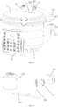
- the correspondence between the reference numerals and the part names in FIG. 1 to FIG. 12 is as follows: 1 cooker body, 11 control panel, 12 power transmitting device, 120 transmitting device mounting portion, 121 first flat coil, 122 second PCB control panel, 123 transmitting device mounting seat, 2 cooker lid, 21 mechanical vent valve, 211 valve seat, 212 valve cover, 22 power receiving device, 220 receiving device mounting portion, 221 second flat coil, 222 first PCB control panel, 223 receiving device mounting seat, 23 motor driving device, 230 rotating shaft, 231 DC motor, 232 transmission gear, 233 rotating rod, 234 rack, 235 transmission lever.
- the present invention provides a split-type electric pressure cooker, comprising a cooker body and a cooker lid cooperating with the cooker body, the cooker body being provided with a power supply device.
- the split-type electric pressure cooker further comprises: a mechanical vent valve, comprising a valve seat and a valve cover, wherein the valve seat is fixedly mounted on the cooker lid, and the valve cover may be movably mounted on the valve seat; a power transmitting device mounted on the cooker body and able to be electrically connected to the power supply device, and the power transmitting device is used to transmit power to the power receiving device; a power receiving device mounted on the cooker lid; and a motor driving device, comprising a driving motor mounted on the cooker lid and electrically connected to the power receiving device, and the motor shaft of the driving motor may drive the valve cover to move so as to open or close the mechanical vent valve; wherein, when the cooker lid is engaged with the cooker body, the power transmitting device cooperates with the power receiving device to realize power transmission; when the cooker lid is opened, the power transmitting device is separated
- the cook body is provided with a power transmitting device
- the cook lid is provided with a power receiving device and a motor driving device.
- the power transmitting device cooperates with the power receiving device to achieve power transmission between the cooker body and the cooker lid, and achieve electronically controlled venting.
- the power transmitting device is connected to the power supply device, and the power supply device transmits the power to the power transmitting device, and the power transmitting device sends the power to the power receiving device, and then the power receiving device transmits power to the driving motor of the motor driving device, so that the driving motor drives the valve cover to move, and open the mechanical vent valve to vent.
- the split-type electric pressure cooker comprises a cooker body 1, a cooker lid 2, a mechanical vent valve 21, a motor driving device 23, a power transmitting device 12, and a power receiving device 22.
- a control panel 11 is mounted in front of the cooker body 1, and a main control panel (i.e. controller) is mounted in the control panel 11, the control panel 11 is provided with a venting switch, the main control panel is electrically connected to the venting switch and the power supply device of the split-type electric pressure cooker.
- the mechanical vent valve 21 comprises a valve seat 211 and a valve cover 212.
- the valve seat 211 is fixedly mounted on the cooker lid 2, and the valve cover 212 is movably mounted on the valve seat 211.
- the motor driving device 23 comprises a DC motor 231, a transmission gear 232 and a rotating rod 233.
- the transmission gear 232 is fixedly connected to the motor shaft, and the rotating rod 233 is rotatably connected to the cooker lid 2 through a rotating shaft 230.
- the first end of the rotating rod 233 is provided with an arc surface, and the rotating shaft 230 is positioned in the center of the arc surface, the arc surface is provided with teeth, the teeth are engaged with the transmission gear 232, and the second end of the rotating rod 233 is in abutment with the bottom of the valve cover 212.
- the power transmitting device 12 comprises a first flat coil 121, a second PCB control panel 122, and a transmitting device mounting seat 123.
- the first flat coil 121 and the second PCB control panel 122 are fixedly mounted on the transmitting device mounting seat 123, and the cooker body 1 is provided with a transmitting device mounting portion 120, and the transmitting device mounting seat 123 is fixedly mounted in the transmitting device mounting portion 120, the first PCB control panel 222 is electrically connected to the main control panel and the first flat coil 121 for supplying an alternating current to the first flat coil 121 under the control of the main control panel, and the first PCB control panel 222 is disposed adjacent to the first flat coil 121, to shorten the power supply distance to the first flat coil 121 and improve the current transmission effect.
- the power receiving device 22 comprises a second flat coil 221, a first PCB control panel 222 having a rectifying circuit, and a receiving device mounting seat 223, the second flat coil 221 and the second PCB control panel 122 are fixedly mounted on the receiving device mounting seat 223, and a receiving device mounting portion 220 is disposed on the cooker lid 2, the receiving device mounting seat 223 is fixedly mounted in the receiving device mounting portion 220, and the second flat coil 221 is electrically connected to the electromagnetic coil of the push-pull electromagnet 3 through the second PCB control panel 122.
- the first flat coil 121 cooperates with the second flat coil 221 to achieve wireless power supply.
- the two flat coils are opposite to each other, and the distance between the two flat coils is relatively short, usually in the range of 0 mm to 50 mm.
- venting switch When venting, users trigger the venting switch, such that the venting switch sends a trigger signal for starting venting to the main control panel, to trigger the internal corresponding program of the main control panel, and the main control panel controls the second PCB control panel 122 to transmit alternating current and valve-opening signal to the first flat coil 121, the changing current makes the first flat coil 121 to generate a changing magnetic field , and the second flat coil 221 generates an alternating induced current affected by the changing magnetic field.
- the first PCB control panel 222 receives the alternating current for alignment and processing, so that the first PCB control panel 222 transmits direct current to the DC motor 231 according to a preset procedure, and the transmission gear 232 mounted on the motor shaft rotates forward with the motor shaft, and the rotating rod 233 rotates under the driving of the transmission gear 232, such that the second end of the rotating rod 233 lifts the valve cover 212, thereby opening the mechanical vent valve 21 for venting.
- the main control panel or the first control plate stops the power supply after the first control plate supplies power to the DC motor 231 for a preset period of time according to its own preset procedure, so that the DC motor 231 is powered off and stopped rotating, to maintain the rotating rod 233 in the current position and thus maintain the valve cover 212 in the current position, and maintain the mechanical vent valve 21 in an open state for continuous venting.
- a user sends a trigger signal of finishing venting to the main control panel through the venting switch, to trigger a corresponding internal control program, so that the main control panel controls the second PCB control panel 122 to transmit current and valve-closing signals to the first flat coil 121, the changing current makes the first flat coil 121 to generate a changing magnetic field, and the second flat coil 221 generates an alternating induced current affected by the changing magnetic field.
- the first PCB control panel 222 receives the alternating current for alignment and processing, so that the first PCB control panel 222 supplies power to the DC motor 231 reversely according to the preset procedure, and the transmission gear 232 rotates reversely with the motor shaft, and the rotating rod 233 rotates reversely and resets under the driving of the transmission gear 232, such that the second end of the rotating rod 233 drops and the valve cover 212 drops and resets accordingly to close the mechanical vent valve 21.
- the main control panel or the first control plate stops the power supply after the first control plate supplies power to the DC motor 231 reversely for a preset period of time according to its own preset procedure, so that the DC motor 231 is powered off and stopped rotating, to maintain the rack 234 and the rotating rod 233 in the current position and maintain the valve cover 212 in the current position, and to maintain the mechanical vent valve 21 in a closed state.
- the venting switch is mounted on the cooker body 1 away from the mechanical vent valve 21 to ensure that user's hands are kept away from the mechanical vent valve 21 when a user pushes the venting switch, thereby preventing the user from being scalded by the discharged steam.
- the first flat coil 121 may be a coil made of copper wire, or a coil etched directly on the first PCB control panel 222.
- the second flat coil 221 may be a coil made of copper wire, or a coil etched directly on the second PCB control panel 122.
- the venting switch has a plurality of venting gear positions, and when the user selects different venting gear positions, the venting switch sends different trigger signal to the main control panel, and different trigger signals trigger different programs of the main control panel to control the power supply duration of the main control panel to the first PCB control panel 222, or allow the main control panel to transmit different valve-opening signals to the first PCB control panel 222, thereby controlling the power supply duration of the first PCB control panel 222 to the DC motor 231, to control the rotation angle of the rotating rod 233 and control the lifting height of the valve cover 212 by the rotating rod 233, that is, the opening degree of the mechanical vent valve 21, so as to adjust the venting velocity of the product.
- the wireless power supply transmission mode by cooperation of the first flat coil 121 with the second flat coil 221 may be replaced with the wireless power supply transmission mode by cooperation of the first cylindrical coil and the second cylindrical coil.
- the technical solution is as follows: the first cylindrical coil is electrically connected to the second PCB control panel 122, and the second cylindrical coil is electrically connected to the first PCB control panel 222. The inner diameters of the two cylindrical coils are different. After the cooker lid 2 is screwed into place, the small cylindrical coil is inserted into the large cylindrical coil to achieve the transmission of current and electrical signals through an electromagnetic induction way.
- the wireless power supply transmission mode by cooperation of the first flat coil 121 with the second flat coil 221 may be replaced with the insertion transmission mode by cooperation of the power plug and the power socket.
- the transmission of current and electrical signals is realized by electrical connection of the power plug and power socket, rather than an electromagnetic induction way. Therefore, it is not necessary to consider the effect of the power supply distance on the induced magnetic field strength, and the second PCB control panel 122 may be omitted.
- one of the power transmitting device 12 and the power receiving device 22 comprises a power socket, and the other comprises a power plug, the power socket and the power plug are electrically connected to the main control panel and the first PCB control panel 222 respectively, when the cooker lid 2 is engaged with the cooker body 1, the insertion of the power plug and the power socket achieves electrical connection, thus achieving the transmission of the current and electrical signals.
- the split-type electric pressure cooker comprises a cooker body 1, a cooker lid 2, a mechanical vent valve 21, a motor driving device 23, a power transmitting device 12, and a power receiving device 22.
- a control panel is mounted in front of the cooker body 1, and a main control panel (i.e. controller) is mounted in the control panel 11, the control panel 11 is provided with a venting switch, the main control panel is electrically connected to the venting switch and the power supply device of the split-type electric pressure cooker.
- the mechanical vent valve 21 comprises a valve seat and a valve cover 212. The valve seat is fixedly mounted on the cooker lid 2, and the valve cover 212 is movably mounted on the valve seat.
- the motor driving device 23 comprises a DC motor 231, a transmission gear 232 and a rack 234.
- the transmission gear 232 is fixedly connected to the motor shaft
- the rack 234 is slidably mounted on the cooker lid 2
- the first end of the rack 234 is engaged with the transmission gear 232
- the second end of the rack 234 is inserted between the valve cover 212 and the valve seat, to lift the valve cover 212, thereby opening the mechanical vent valve 21.
- the power transmitting device 12 comprises a first flat coil 121, a second PCB control panel 122, and a transmitting device mounting seat.
- the first flat coil 121 and the second PCB control panel 122 are fixedly mounted on the transmitting device mounting seat, and the cooker body 1 is provided with a transmitting device mounting portion, and the transmitting device mounting seat is fixedly mounted in the transmitting device mounting portion, the first PCB control panel 222 is electrically connected to the main control panel and the first flat coil 121 for supplying an alternating current to the first flat coil 121 under the control of the main control panel, and the first PCB control panel 222 is disposed adjacent to the first flat coil 121, to shorten the power supply distance to the first flat coil 121 and improve the current transmission effect.
- the power receiving device 22 comprises a second flat coil 221, a first PCB control panel 222 having a rectifying circuit, and a receiving device mounting seat, the second flat coil 221 and the second PCB control panel 122 are fixedly mounted on the receiving device mounting seat, and a receiving device mounting portion is disposed on the cooker lid 2, the receiving device mounting seat is fixedly mounted in the receiving device mounting portion, and the second flat coil 221 is electrically connected to the electromagnetic coil of the push-pull electromagnet 3 through the second PCB control panel 122.
- the first flat coil 121 cooperates with the second flat coil 221 to achieve wireless power supply.
- the two flat coils are opposite to each other, and the distance between the two flat coils is relatively short, usually in the range of 0 mm to 50 mm.
- venting switch When venting, users trigger the venting switch, such that the venting switch sends a trigger signal for starting venting to the main control panel, to trigger the internal corresponding program of the main control panel, and the main control panel controls the second PCB control panel 122 to transmit alternating current and valve-opening signal to the first flat coil 121, the changing current makes the first flat coil 121 to generate a changing magnetic field , and the second flat coil 221 generates an alternating induced current affected by the changing magnetic field.
- the first PCB control panel 222 receives the alternating current for alignment and processing, so that the first PCB control panel 222 transmits direct current to the DC motor 231 according to a preset program, and the transmission gear 232 mounted on the motor shaft rotates forward with the motor shaft, and the rack 234 slides towards the direction of the axis of the valve cover 212 under the driving of the transmission gear 232, such that the second end of the rack 234 is inserted between the valve cover 212 and the valve seat, to lift the valve cover 212, thereby opening the mechanical vent valve 21 for venting.
- the main control panel or the first control plate stops the power supply after the first control plate supplies power to the DC motor 231 for a preset period of time according to its own preset procedure, so that the DC motor 231 is powered off and stopped rotating, to maintain the rotating rod 233 in the current position and thus maintain the valve cover 212 in the current position, and maintain the mechanical vent valve 21 in an open state for continuous venting.
- a user sends a trigger signal of finishing venting to the main control panel through the venting switch, to trigger a corresponding internal control program, so that the main control panel controls the second PCB control panel 122 to transmit current and valve-closing signals to the first flat coil 121, the changing current makes the first flat coil 121 to generate a changing magnetic field, and the second flat coil 221 generates an alternating induced current affected by the changing magnetic field.
- the first PCB control panel 222 receives the alternating current for alignment and processing, so that the first PCB control panel 222 supplies power to the DC motor 231 reversely according to the preset program, and the transmission gear 232 rotates reversely with the motor shaft, and the rack 234 slides in a direction away from the axis of the valve cover 212 under the driving of the transmission gear 232, such that the second end of the rack 234 is withdrawn between the valve cover 212 and the valve seat, and the valve cover 212 drops and resets accordingly to close the mechanical vent valve 21.
- the main control panel or the first control plate stops the power supply after the first control plate supplies power to the DC motor 231 reversely for a preset period of time according to its own preset program, so that the DC motor 231 is powered off and stopped rotating, to control the position of the rack 234.
- the venting switch is mounted on the cooker body 1 away from the mechanical vent valve 21 to ensure that user's hands are kept away from the mechanical vent valve 21 when a user pushes the venting switch, thereby preventing the user from being scalded by the discharged steam.
- the first flat coil 121 may be a coil made of copper wire, or a coil etched directly on the first PCB control panel 222.
- the second flat coil 221 may be a coil made of copper wire, or a coil etched directly on the second PCB control panel 122.
- the second end of the rack 234 is provided with a guide ramp, and the guide ramp is in abutment with the bottom of the valve cover 212.
- the height of the valve cover 212 lifted by the guide ramp is controlled by a slide distance of the rack 234.
- the venting switch has a plurality of venting gear positions, and when the user selects different venting gear positions, the venting switch sends different trigger signals to the main control panel, and different trigger signals trigger different programs of the main control panel to control the power supply duration of the main control panel to the first PCB control panel 222, or allow the main control panel to transmit different valve-opening signals to the first PCB control panel 222, thereby controlling the power supply duration of the first PCB control panel 222 to the DC motor 231, to control the slide distance of the rack 234 and thus control the lifting height of the valve cover 212 by the guide ramp of the rack 234, that is, the opening degree of the mechanical vent valve 21, so as to adjust the venting velocity of the product.
- the wireless power supply transmission mode by cooperation of the first flat coil 121 with the second flat coil 221 may be replaced with the wireless power supply transmission mode by cooperation of the first cylindrical coil and the second cylindrical coil.
- the technical solution is as follows: the first cylindrical coil is electrically connected to the second PCB control panel 122, and the second cylindrical coil is electrically connected to the first PCB control panel 222. The inner diameters of the two cylindrical coils are different. After the cooker lid 2 is screwed into place, the small cylindrical coil is inserted into the large cylindrical coil to achieve the transmission of current and electrical signals through an electromagnetic induction way.
- the wireless power supply transmission mode by cooperation of the first flat coil 121 with the second flat coil 221 may be replaced with the insertion transmission mode by cooperation of the power plug and the power socket.
- the transmission of current and electrical signals is realized by electrical connection of the power plug and power socket, rather than an electromagnetic induction way. Therefore, it is not necessary to consider the effect of the power supply distance on the induced magnetic field strength, and the second PCB control panel 122 may be omitted.
- one of the power transmitting device 12 and the power receiving device 22 comprises a power socket, and the other comprises a power plug, and the power socket and the power plug are electrically connected to the main control panel and the first PCB control panel 222 respectively, when the cooker lid 2 is engaged with the cooker body 1, the insertion of the power plug and the power socket achieves electrical connection, thus achieving the transmission of the current and electrical signals.
- the split-type electric pressure cooker comprises a cooker body 1, a cooker lid 2, a mechanical vent valve 21, a motor driving device 23, a power transmitting device 12, and a power receiving device 22.
- a control panel 11 is mounted in front of the cooker body 1, and a main control panel (i.e. controller) is mounted in the control panel 11, the control panel 11 is provided with a venting switch, the main control panel is electrically connected to the venting switch and the power supply device of the split-type electric pressure cooker.
- the mechanical vent valve 21 comprises a valve seat and a valve cover 212. The valve seat is fixedly mounted on the cooker lid 2, and the valve cover 212 is movably mounted on the valve seat.
- the motor driving device 23 comprises a DC motor 231, a transmission gear 232, a rack 234 and a transmission lever 235.
- the transmission gear 232 is fixedly connected to the motor shaft, the rack 234 is slidably mounted on the cooker lid 2 and is engaged with the transmission gear 232; the middle portion of the transmission lever 235 is rotatably connected to the cooker lid 2, the top portion of the first end of the transmission lever 235 may be in abutment with the bottom of the rack 234, and the top portion of the second end of the transmission lever 235 may be in abutment with the bottom of the valve cover 212, so that the transmission lever 235 may drive the valve cover 212 to move under the push of the rack 234.
- the power transmitting device 12 comprises a first flat coil 121, a second PCB control panel 122, and a transmitting device mounting seat.
- the first flat coil 121 and the second PCB control panel 122 are fixedly mounted on the transmitting device mounting seat, and the cooker body 1 is provided with a transmitting device mounting portion, and the transmitting device mounting seat is fixedly mounted in the transmitting device mounting portion, the first PCB control panel 222 is electrically connected to the main control panel and the first flat coil 121 for supplying an alternating current to the first flat coil 121 under the control of the main control panel, and the first PCB control panel 222 is disposed adjacent to the first flat coil 121, to shorten the power supply distance to the first flat coil 121 and improve the current transmission effect.
- the power receiving device 22 comprises a second flat coil 221, a first PCB control panel 222 having a rectifying circuit, and a receiving device mounting seat, the second flat coil 221 and the second PCB control panel 122 are fixedly mounted on the receiving device mounting seat, and a receiving device mounting portion is disposed on the cooker lid 2, the receiving device mounting seat is fixedly mounted in the receiving device mounting portion, and the second flat coil 221 is electrically connected to the electromagnetic coil of the push-pull electromagnet 3 through the second PCB control panel 122.
- the first flat coil 121 cooperates with the second flat coil 221 to achieve wireless power supply.
- the two flat coils are opposite to each other, and the distance between the two flat coils is relatively short, usually in the range of 0 mm to 50 mm.
- venting switch When venting, users trigger the venting switch, such that the venting switch sends a trigger signal for starting venting to the main control panel, to trigger the internal corresponding program of the main control panel, and the main control panel controls the second PCB control panel 122 to transmit alternating current and valve-opening signal to the first flat coil 121, the changing current makes the first flat coil 121 to generate a changing magnetic field , and the second flat coil 221 generates an alternating induced current affected by the changing magnetic field.
- the first PCB control panel 222 receives the alternating current for alignment and processing, so that the first PCB control panel 222 transmits direct current to the DC motor 231 according to a preset program, and the transmission gear 232 mounted on the motor shaft rotates forward with the motor shaft, and the rack 234 slides downwardly under the driving of the transmission gear 232, by pressing down the first end of the transmission lever 235, the second end of the transmission lever 235 warps up to lift the valve cover 212, thereby opening the mechanical vent valve 21 for venting.
- the main control panel or the first control plate stops the power supply after the first control plate supplies power to the DC motor 231 for a preset period of time according to its own preset program, so that the DC motor 231 is powered off and stopped rotating, to maintain the rotating rod 233 in the current position and thus maintain the valve cover 212 in the current position, and maintain the mechanical vent valve 21 in an open state for continuous venting.
- a user sends a trigger signal of finishing venting to the main control panel through the venting switch, to trigger a corresponding internal control program, so that the main control panel controls the second PCB control panel 122 to transmit current and valve-closing signals to the first flat coil 121, the changing current makes the first flat coil 121 to generate a changing magnetic field , and the second flat coil 221 generates an alternating induced current affected by the changing magnetic field.
- the first PCB control panel 222 receives the alternating current for alignment and processing, so that the first PCB control panel 222 supplies power to the DC motor 231 reversely according to the preset program, and the transmission gear 232 rotates reversely with the motor shaft, and the rack 234 slides upwardly under the driving of the transmission gear 232, the transmission lever 235 is reversed and reset under its own gravity, such that the second end of the transmission lever 235 drops and the valve cover 212 then falls back and resets under its own gravity to close the mechanical vent valve 21.
- the main control panel or the first control plate stops the power supply after the first control plate supplies power to the DC motor 231 reversely for a preset period of time according to its own preset program, so that the DC motor 231 is powered off and stopped rotating, to control the position of the rack 234.
- the venting switch is mounted on the cooker body 1 away from the mechanical vent valve 21 to ensure that user's hands are kept away from the mechanical vent valve 21 when a user pushes the venting switch, thereby preventing the user from being scalded by the discharged steam.
- the first flat coil 121 may be a coil made of copper wire, or a coil etched directly on the first PCB control panel 222.
- the second flat coil 221 may be a coil made of copper wire or a coil etched directly on the second PCB control panel 122.
- the venting switch has a plurality of venting gear positions, and when the user selects different venting gear positions, the venting switch sends different trigger signal to the main control panel, and different trigger signals trigger different programs of the main control panel to control the power supply duration of the main control panel to the first PCB control panel 222, or allow the main control panel to transmit different valve-opening signals to the first PCB control panel 222, thereby controlling the power supply duration of the first PCB control panel 222 to the DC motor 231, to control the distance pressed down on the transmission lever 235 by the rack 234 and control the lifting height of the valve cover 212 by the transmission lever 235, that is, the opening degree of the mechanical vent valve 21, so as to adjust the venting velocity of the product.
- the wireless power supply transmission mode by cooperation of the first flat coil 121 with the second flat coil 221 may be replaced with the wireless power supply transmission mode by cooperation of the first cylindrical coil and the second cylindrical coil.
- the technical solution is as follows: the first cylindrical coil is electrically connected to the second PCB control panel 122, and the second cylindrical coil is electrically connected to the first PCB control panel 222. The inner diameters of the two cylindrical coils are different. After the cooker lid 2 is screwed into place, the small cylindrical coil is inserted into the large cylindrical coil to achieve the transmission of current and electrical signals through an electromagnetic induction way.
- the wireless power supply transmission mode by cooperation of the first flat coil 121 with the second flat coil 221 may be replaced with the insertion transmission mode by cooperation of the power plug and the power socket.
- the transmission of current and electrical signals is realized by electrical connection of the power plug and power socket, rather than an electromagnetic induction way. Therefore, it is not necessary to consider the effect of the power supply distance on the induced magnetic field strength, and the second PCB control panel 122 may be omitted.
- one of the power transmitting device 12 and the power receiving device 22 comprises a power socket, and the other comprises a power plug, the power socket and the power plug are electrically connected to the main control panel and the first PCB control panel 222 respectively, when the cooker lid 2 is engaged with the cooker body 1, the insertion of the power plug and the power socket achieves electrical connection, thus achieving the transmission of the current and electrical signals.
Landscapes
- Engineering & Computer Science (AREA)
- Food Science & Technology (AREA)
- Cookers (AREA)
- Connection Of Motors, Electrical Generators, Mechanical Devices, And The Like (AREA)
Claims (15)
- Autocuiseur électrique du type à séparation, comprenant un corps d'autocuiseur (1) et un couvercle d'autocuiseur (2) coopérant avec le corps d'autocuiseur (1), le corps d'autocuiseur (1) étant pourvu d'un dispositif d'alimentation en énergie, dans lequel l'autocuiseur électrique du type à séparation comprend en outre :une soupape d'évacuation mécanique (21) comprenant un siège de soupape (211) et un couvercle de soupape (212), le siège de soupape (211) étant monté fixement sur le couvercle d'autocuiseur (2), et le couvercle de soupape (212) pouvant être monté de façon mobile sur le siège de soupape (211) ;un dispositif de réception d'énergie (22) monté sur le couvercle d'autocuiseur (2) ;un dispositif d'entraînement à moteur (23) comprenant un moteur d'entraînement monté sur le couvercle d'autocuiseur (2) et relié électriquement au dispositif de réception d'énergie (22), et l'arbre de moteur du moteur d'entraînement étant capable d'entraîner le couvercle de soupape (212) pour déplacer celui-ci de manière à ouvrir ou fermer la soupape d'évacuation mécanique (21) ;caractérisé en ce que l'autocuiseur électrique du type à séparation comprend en outre :un dispositif de transmission d'énergie (12) monté sur le corps d'autocuiseur (1) et susceptible d'être relié électriquement au dispositif d'alimentation en énergie, et le dispositif de transmission d'énergie (12) étant utilisé pour transmettre de l'énergie au dispositif de réception d'énergie (22) ;dans lequel, lorsque le couvercle d'autocuiseur (2) est engagé avec le corps d'autocuiseur (1), le dispositif de transmission d'énergie (12) coopère avec le dispositif de réception d'énergie (22) pour assurer la transmission d'énergie ; lorsque le couvercle d'autocuiseur (2) est ouvert, le dispositif de transmission d'énergie (12) est séparé du dispositif de réception d'énergie (22).
- Autocuiseur électrique du type à séparation selon la revendication 1, dans lequel le moteur d'entraînement est un moteur à courant continu (231), le dispositif de réception d'énergie (22) comprend une première plaque de commande, et la première plaque de commande est reliée électriquement au moteur à courant continu (231) pour transmettre du courant direct au moteur à courant continu (231), et pour commander la direction de rotation du moteur à courant continu (231) en commandant la direction du courant direct, pour ouvrir ou fermer la soupape d'évacuation mécanique (21).
- Autocuiseur électrique du type à séparation selon la revendication 2, dans lequel le dispositif d'entraînement à moteur (23) comprend en outre :
un ensemble de transmission monté de façon mobile sur le couvercle d'autocuiseur (2), et l'ensemble de transmission coopérant avec l'arbre de moteur et le couvercle de soupape (212), le moteur d'entraînement étant capable d'entraîner le couvercle de soupape (212) pour le déplacement de celui-ci à travers l'ensemble de transmission, pour ouvrir ou fermer la soupape d'évacuation mécanique (21). - Autocuiseur électrique du type à séparation selon la revendication 3, dans lequel l'ensemble de transmission comprend :un engrenage de transmission (232) relié fixement à l'arbre de moteur ;une tige rotative (233) reliée de façon rotative au couvercle d'autocuiseur (2) par un arbre de rotation (230), une première extrémité de la tige rotative (233) étant pourvue d'une surface arquée, l'arbre de rotation (230) étant situé au centre de la surface arquée, la surface arquée étant pourvue d'une dent, et la dent étant engagée avec l'engrenage de transmission (232), et une deuxième extrémité de la tige rotative (233) coopérant avec le couvercle de soupape (212) et pouvant entraîner le couvercle de soupape (212) pour déplacer celui-ci.
- Autocuiseur électrique du type à séparation selon la revendication 3, dans lequel l'ensemble de transmission comprend :un engrenage de transmission (232) relié fixement à l'arbre de moteur ;une crémaillère (234) monté de façon coulissante sur le couvercle d'autocuiseur (2), la première extrémité de la crémaillère (234) étant engagée avec l'engrenage de transmission (232), et la deuxième extrémité de la crémaillère (234) coopérant avec le couvercle de soupape (212) et pouvant entraîner le couvercle de soupape (212) pour déplacer celui-ci.
- Autocuiseur électrique du type à séparation selon la revendication 3, dans lequel
un engrenage de transmission (232) est relié fixement à l'arbre de moteur ;
une crémaillère (234) est montée de façon coulissante sur le couvercle d'autocuiseur (2) tout en étant engagée avec l'engrenage de transmission (232) ;
un levier de transmission (235) dont la partie du milieu est reliée de façon rotative au couvercle d'autocuiseur (2), les deux extrémités du levier de transmission (235) coopérant avec la crémaillère (234) et le couvercle de soupape (212) respectivement, de telle façon que le levier de transmission (235) est capable d'entraîner le couvercle de soupape (212) pour déplacer celui-ci sous l'entraînement de la crémaillère (234). - Autocuiseur électrique du type à séparation selon la revendication 2, dans lequel
le dispositif de transmission d'énergie (12) comprend une première bobine plate (121), le dispositif d'alimentation en énergie est configuré pour transmettre un courant alternatif à la première bobine plate (121), et le dispositif de réception d'énergie (22) comprend une deuxième bobine plate (221) ;
dans lequel, lorsque le couvercle d'autocuiseur (2) est engagé avec le corps d'autocuiseur (1), la première bobine plate (121) est opposée à la deuxième bobine plate (221). - Autocuiseur électrique du type à séparation selon la revendication 7, dans lequel
le dispositif de réception d'énergie (22) comprend en outre un dispositif redresseur, la deuxième bobine plate (221) est reliée électriquement à la première plaque de commande par le biais du dispositif redresseur, et le dispositif redresseur est utilisé pour convertir un courant alternatif transmis par la deuxième bobine plate (221) en courant direct et pour transmettre le courant direct à la première plaque de commande. - Autocuiseur électrique du type à séparation selon la revendication 2, dans lequel
le dispositif de transmission d'énergie (12) comprend une première bobine cylindrique, le dispositif d'alimentation en énergie est configuré pour fournir un courant alternatif à la première bobine cylindrique, et le dispositif de réception d'énergie (22) comprend une deuxième bobine cylindrique, et le diamètre intérieur de la première bobine cylindrique n'est pas identique à celui de la deuxième bobine cylindrique ;
dans lequel, lorsque le couvercle d'autocuiseur (2) est engagé avec le corps d'autocuiseur (1), l'une parmi la première bobine cylindrique et la deuxième bobine cylindrique s'étend dans l'autre. - Autocuiseur électrique du type à séparation selon la revendication 9, dans lequel
le dispositif de réception d'énergie (22) comprend en outre un dispositif redresseur, la deuxième bobine cylindrique est reliée électriquement à la première plaque de commande par le biais du dispositif redresseur, et le dispositif redresseur est utilisé pour convertir un courant alternatif transmis par la deuxième bobine cylindrique en courant direct et pour transmettre le courant direct à la première plaque de commande. - Autocuiseur électrique du type à séparation selon la revendication 2, dans lequel
l'un parmi le dispositif de transmission d'énergie (12) et le dispositif de réception d'énergie (22) comprend une prise électrique, et l'autre comprend une fiche secteur, et lorsque le couvercle d'autocuiseur (2) est engagé avec le corps d'autocuiseur (1), la fiche secteur coopère avec la prise électrique. - Autocuiseur électrique du type à séparation selon la revendication 11, dans lequel
le dispositif de réception d'énergie (22) comprend en outre un dispositif redresseur, et la prise électrique ou la fiche secteur dans le dispositif de réception d'énergie (22) est reliée électriquement au moteur à courant continu (231) par le biais du dispositif redresseur, le dispositif redresseur étant configuré pour convertir un courant alternatif transmis par la prise électrique ou la fiche secteur en courant direct et pour transmettre le courant direct à la première plaque de commande ; ou
le dispositif de transmission d'énergie (12) comprend en outre un dispositif redresseur, et la prise électrique ou la fiche secteur dans le dispositif de transmission d'énergie (12) est reliée au dispositif d'alimentation en énergie par le biais du dispositif redresseur, et le dispositif redresseur est configuré pour convertir un courant alternatif transmis par le dispositif d'alimentation en énergie en courant direct, et pour transmettre le courant direct à la prise électrique ou la fiche secteur connectée à celui-ci. - Autocuiseur électrique du type à séparation selon l'une quelconque des revendications 2 à 11, comprenant en outre :
un commutateur de ventilation et un dispositif de commande montés sur le corps d'autocuiseur (1), le dispositif de commande étant relié électriquement au dispositif d'alimentation en énergie, au commutateur de ventilation et au dispositif de transmission d'énergie (12), et le commutateur de ventilation étant configuré pour envoyer un signal déclencheur au dispositif de commande, de manière à ce que le dispositif de commande transmette de l'énergie au dispositif de transmission d'énergie (12) en fonction du signal déclencheur. - Autocuiseur électrique du type à séparation selon la revendication 13, dans lequel
le dispositif de commande ou la première plaque de commande est en outre configuré(e) pour commander une position du couvercle de soupape (212) en commandant la durée d'alimentation en énergie du moteur à courant continu (231), de manière à commander un degré d'ouverture de la soupape d'évacuation mécanique (21). - Autocuiseur électrique du type à séparation selon l'une quelconque des revendications 7 à 10, dans lequel
le dispositif de transmission d'énergie (12) comprend en outre une deuxième plaque de commande, la deuxième plaque de commande est disposée à côté de la première bobine plate (121) ou de la première bobine cylindrique dans le dispositif de transmission d'énergie (12), et la deuxième plaque de commande étant reliée électriquement à la première bobine plate (121) ou à la première bobine cylindrique et au dispositif d'alimentation en énergie.
Applications Claiming Priority (3)
| Application Number | Priority Date | Filing Date | Title |
|---|---|---|---|
| CN201611110267.1A CN108143259A (zh) | 2016-12-02 | 2016-12-02 | 分体式电压力锅 |
| CN201621316295.4U CN206761370U (zh) | 2016-12-02 | 2016-12-02 | 分体式电压力锅 |
| PCT/CN2017/108939 WO2018099233A1 (fr) | 2016-12-02 | 2017-11-01 | Autocuiseur électrique de type partagé |
Publications (3)
| Publication Number | Publication Date |
|---|---|
| EP3536199A1 EP3536199A1 (fr) | 2019-09-11 |
| EP3536199A4 EP3536199A4 (fr) | 2019-10-16 |
| EP3536199B1 true EP3536199B1 (fr) | 2020-10-07 |
Family
ID=62242287
Family Applications (1)
| Application Number | Title | Priority Date | Filing Date |
|---|---|---|---|
| EP17876662.2A Active EP3536199B1 (fr) | 2016-12-02 | 2017-11-01 | Autocuiseur électrique de type partagé |
Country Status (4)
| Country | Link |
|---|---|
| US (1) | US11154154B2 (fr) |
| EP (1) | EP3536199B1 (fr) |
| CA (1) | CA3045705C (fr) |
| WO (1) | WO2018099233A1 (fr) |
Families Citing this family (29)
| Publication number | Priority date | Publication date | Assignee | Title |
|---|---|---|---|---|
| CN110123159A (zh) | 2017-08-09 | 2019-08-16 | 沙克忍者运营有限责任公司 | 烹饪系统 |
| USD914436S1 (en) | 2018-06-19 | 2021-03-30 | Sharkninja Operating Llc | Air diffuser with food preparation pot |
| USD903413S1 (en) | 2018-08-09 | 2020-12-01 | Sharkninja Operating Llc | Cooking basket |
| USD883015S1 (en) | 2018-08-09 | 2020-05-05 | Sharkninja Operating Llc | Food preparation device and parts thereof |
| USD934027S1 (en) | 2018-08-09 | 2021-10-26 | Sharkninja Operating Llc | Reversible cooking rack |
| USD883014S1 (en) | 2018-08-09 | 2020-05-05 | Sharkninja Operating Llc | Food preparation device |
| EP3698683B1 (fr) * | 2019-02-20 | 2021-11-03 | LG Electronics Inc. | Appareil de cuisson à chauffage par induction |
| WO2020171418A1 (fr) * | 2019-02-20 | 2020-08-27 | 엘지전자 주식회사 | Cuiseur à riz à chauffage par induction sans fil et système de chauffage par induction sans fil comprenant ce dernier |
| CN212788226U (zh) | 2019-02-25 | 2021-03-26 | 沙克忍者运营有限责任公司 | 烹饪系统 |
| US20190254476A1 (en) | 2019-02-25 | 2019-08-22 | Sharkninja Operating Llc | Cooking device and components thereof |
| USD926513S1 (en) * | 2019-05-09 | 2021-08-03 | Nuwave, Llc | Combined air fryer and pressure cooker base unit |
| USD982375S1 (en) | 2019-06-06 | 2023-04-04 | Sharkninja Operating Llc | Food preparation device |
| USD918654S1 (en) | 2019-06-06 | 2021-05-11 | Sharkninja Operating Llc | Grill plate |
| US11839327B2 (en) * | 2019-07-26 | 2023-12-12 | Sunbeam Products, Inc. | Lid for cooking appliance |
| CN110664262B (zh) * | 2019-10-25 | 2024-12-17 | 朱奕菲 | 一种高压锅内锅加热装置 |
| US11647861B2 (en) | 2020-03-30 | 2023-05-16 | Sharkninja Operating Llc | Cooking device and components thereof |
| USD955802S1 (en) * | 2020-04-30 | 2022-06-28 | Beijing Xiaomi Mobile Software Co., Ltd. | Electric pressure cooker |
| USD961330S1 (en) * | 2020-07-16 | 2022-08-23 | Midea Group Co., Ltd. | Electric cooker lid |
| CA200978S (en) * | 2020-07-16 | 2021-11-25 | Midea Group Co Ltd | Multifunctional cooking pot |
| USD960640S1 (en) * | 2020-07-16 | 2022-08-16 | Midea Group Co., Ltd. | Lid for a pressure cooker |
| USD964089S1 (en) * | 2020-07-16 | 2022-09-20 | Midea Group Co., Ltd. | Portion of a pressure cooker |
| CA200996S (en) * | 2020-07-16 | 2021-11-24 | Midea Group Co Ltd | Pot lid |
| CA200634S (en) * | 2020-08-31 | 2021-12-06 | Midea Group Co Ltd | Pressure cooker |
| CN112545320B (zh) * | 2020-12-10 | 2022-02-11 | 健仕(宁波)智能电器制造有限公司 | 一种带有内嵌式空气过滤装置的智能微压蒸汽烤箱 |
| CN112690669B (zh) * | 2021-02-03 | 2022-09-13 | 佛山市顺德区奥格电器有限公司 | 一种多功能料理的集成实现方法 |
| US11882860B2 (en) * | 2021-10-21 | 2024-01-30 | Sharkninja Operating Llc | Venting for a combination cooking system |
| CN115265172A (zh) * | 2022-06-15 | 2022-11-01 | 佛山市天禄智能装备科技有限公司 | 一种用于回转窑的防爆系统以及回转窑 |
| CN115789706A (zh) * | 2022-11-15 | 2023-03-14 | 湖南鸿坤电器股份有限公司 | 一种超声波智能安全监测方法、系统及可读存储介质 |
| FR3158029B1 (fr) * | 2024-01-05 | 2026-02-20 | Seb Sa | Appareil de cuisson électrique multifonction |
Family Cites Families (30)
| Publication number | Priority date | Publication date | Assignee | Title |
|---|---|---|---|---|
| JPS5698382A (en) * | 1979-12-29 | 1981-08-07 | General Res Obu Erekutoronitsukusu:Kk | Controlling device of motor |
| US4799914A (en) * | 1987-02-09 | 1989-01-24 | Hutchinson Jack M | Remote control lighter-than-air toy with tether |
| US7154069B1 (en) * | 2001-10-30 | 2006-12-26 | Henny Penny Corporation | Cooking apparatus and methods of employing such apparatus |
| JP4092355B2 (ja) * | 2005-12-28 | 2008-05-28 | 象印マホービン株式会社 | 圧力調理器の調圧方法および圧力調理器 |
| CN100588351C (zh) * | 2007-12-05 | 2010-02-10 | 广东格兰仕集团有限公司 | 电压力锅的锅盖安全锁紧装置及其控制方法 |
| US9473209B2 (en) * | 2008-08-20 | 2016-10-18 | Intel Corporation | Wireless power transfer apparatus and method thereof |
| US7990103B2 (en) * | 2008-11-24 | 2011-08-02 | Sony Ericsson Mobile Communications Ab | Portable electronic apparatus, and battery charging system comprising an antenna arrangement for a radio receiver |
| JP5262785B2 (ja) * | 2009-02-09 | 2013-08-14 | 株式会社豊田自動織機 | 非接触電力伝送装置 |
| CN201612491U (zh) * | 2009-12-28 | 2010-10-27 | 浙江苏泊尔家电制造有限公司 | 一种可实现无线控制的烹饪锅具 |
| US8912686B2 (en) * | 2010-11-04 | 2014-12-16 | Access Business Group International Llc | Wireless power system and method with improved alignment |
| CN202287758U (zh) * | 2011-05-09 | 2012-07-04 | 九阳股份有限公司 | 一种分体式电压力锅 |
| US9948145B2 (en) * | 2011-07-08 | 2018-04-17 | Witricity Corporation | Wireless power transfer for a seat-vest-helmet system |
| CN202341762U (zh) * | 2011-10-27 | 2012-07-25 | 九阳股份有限公司 | 自动排气电压力锅 |
| US9917478B2 (en) * | 2011-11-18 | 2018-03-13 | Toyota Jidosha Kabushiki Kaisha | Power transmission device, power reception device and power transfer system |
| CN202408447U (zh) * | 2011-11-29 | 2012-09-05 | 九阳股份有限公司 | 一种压控式电压力锅 |
| US9496746B2 (en) * | 2013-05-15 | 2016-11-15 | The Regents Of The University Of Michigan | Wireless power transmission for battery charging |
| US9872582B2 (en) * | 2013-07-26 | 2018-01-23 | Midea Group Co., Ltd. | Electric pressure cooker |
| KR101458598B1 (ko) * | 2014-03-14 | 2014-11-11 | 김차식 | 전기밥솥 |
| CN203885262U (zh) * | 2014-04-30 | 2014-10-22 | 九阳股份有限公司 | 一种电热锅 |
| JP6397941B2 (ja) * | 2014-06-25 | 2018-09-26 | コーニンクレッカ フィリップス エヌ ヴェKoninklijke Philips N.V. | 無線誘導電力伝送 |
| US11031826B2 (en) * | 2014-09-11 | 2021-06-08 | Auckland Uniservices Limited | Magnetic flux coupling structures with controlled flux cancellation |
| US10103553B2 (en) * | 2014-10-22 | 2018-10-16 | Lg Electronics Inc. | Wireless power transmitter and receiver |
| WO2016140465A1 (fr) * | 2015-03-04 | 2016-09-09 | 엘지전자(주) | Émetteur et récepteur de puissance sans fil |
| KR102579343B1 (ko) * | 2015-06-11 | 2023-09-15 | 엘지전자 주식회사 | 무선 전력 전송 시스템의 구조 |
| CN205107318U (zh) * | 2015-09-25 | 2016-03-30 | 佛山市顺德区美的电热电器制造有限公司 | 上盖组件和烹饪器具 |
| WO2017049635A1 (fr) * | 2015-09-25 | 2017-03-30 | 佛山市顺德区美的电热电器制造有限公司 | Cuiseur électrique |
| CN205083264U (zh) * | 2015-11-10 | 2016-03-16 | 广东创迪电器有限公司 | 一种分体式电压力锅 |
| CN205849251U (zh) * | 2016-02-01 | 2017-01-04 | 浙江绍兴苏泊尔生活电器有限公司 | 电压力锅 |
| US10601249B2 (en) * | 2016-03-09 | 2020-03-24 | Lg Electronics Inc. | Wireless power transmitter and receiver |
| US10530426B2 (en) * | 2016-09-23 | 2020-01-07 | Lg Electronics Inc. | Wireless power transferring method and device therefor |
-
2017
- 2017-11-01 US US16/466,285 patent/US11154154B2/en active Active
- 2017-11-01 EP EP17876662.2A patent/EP3536199B1/fr active Active
- 2017-11-01 CA CA3045705A patent/CA3045705C/fr active Active
- 2017-11-01 WO PCT/CN2017/108939 patent/WO2018099233A1/fr not_active Ceased
Non-Patent Citations (1)
| Title |
|---|
| None * |
Also Published As
| Publication number | Publication date |
|---|---|
| EP3536199A1 (fr) | 2019-09-11 |
| WO2018099233A1 (fr) | 2018-06-07 |
| US11154154B2 (en) | 2021-10-26 |
| CA3045705C (fr) | 2021-04-06 |
| US20200000263A1 (en) | 2020-01-02 |
| EP3536199A4 (fr) | 2019-10-16 |
| CA3045705A1 (fr) | 2018-06-07 |
Similar Documents
| Publication | Publication Date | Title |
|---|---|---|
| EP3536199B1 (fr) | Autocuiseur électrique de type partagé | |
| US12268335B2 (en) | Kitchen device | |
| JP6127044B2 (ja) | 電気機械方式取り外し可能把握装置 | |
| US20140238978A1 (en) | Non-contact power receiving device and non-contact power transmission device | |
| CN103565301B (zh) | 电动食物加工机 | |
| EP2859776B1 (fr) | Appareil de cuisine sans fil | |
| WO2013094174A1 (fr) | Appareil d'alimentation sans contact et système de transmission d'alimentation sans contact | |
| CN108143259A (zh) | 分体式电压力锅 | |
| AU2020328375A1 (en) | Blender | |
| CN102389253A (zh) | 一种电磁炉用可实现立体加热的锅具组件 | |
| WO2017005526A1 (fr) | Appareil de préparation d'aliments | |
| US12527438B2 (en) | Blender | |
| CN104997391A (zh) | 一种压力调节机构及设有该压力调节机构的压力锅 | |
| CN213464775U (zh) | 烹饪器具 | |
| EP3202233B1 (fr) | Appareil de préparation culinaire | |
| EP2363647B1 (fr) | Système de commande pour un appareil | |
| CN206761370U (zh) | 分体式电压力锅 | |
| WO2016102090A1 (fr) | Appareil de préparation des aliments | |
| KR20170101040A (ko) | 스마트기기 무선충전형 인덕션 쿠커 | |
| CN114081331B (zh) | 烹饪器具 | |
| CN107625412B (zh) | 烹饪器具及其无线控制系统 | |
| CN220141342U (zh) | 一种多功能的底座及烹饪器具 | |
| KR20160043310A (ko) | 자동식 압력 잠금 및 해제 기능을 구비한 전기 밥솥 | |
| CN219103073U (zh) | 烹饪器具 | |
| CN209712527U (zh) | 一种新型可调控式温控器 |
Legal Events
| Date | Code | Title | Description |
|---|---|---|---|
| STAA | Information on the status of an ep patent application or granted ep patent |
Free format text: STATUS: THE INTERNATIONAL PUBLICATION HAS BEEN MADE |
|
| PUAI | Public reference made under article 153(3) epc to a published international application that has entered the european phase |
Free format text: ORIGINAL CODE: 0009012 |
|
| STAA | Information on the status of an ep patent application or granted ep patent |
Free format text: STATUS: REQUEST FOR EXAMINATION WAS MADE |
|
| 17P | Request for examination filed |
Effective date: 20190603 |
|
| AK | Designated contracting states |
Kind code of ref document: A1 Designated state(s): AL AT BE BG CH CY CZ DE DK EE ES FI FR GB GR HR HU IE IS IT LI LT LU LV MC MK MT NL NO PL PT RO RS SE SI SK SM TR |
|
| AX | Request for extension of the european patent |
Extension state: BA ME |
|
| A4 | Supplementary search report drawn up and despatched |
Effective date: 20190916 |
|
| RIC1 | Information provided on ipc code assigned before grant |
Ipc: A47J 27/08 20060101AFI20190910BHEP Ipc: A47J 27/09 20060101ALI20190910BHEP |
|
| DAV | Request for validation of the european patent (deleted) | ||
| DAX | Request for extension of the european patent (deleted) | ||
| GRAP | Despatch of communication of intention to grant a patent |
Free format text: ORIGINAL CODE: EPIDOSNIGR1 |
|
| STAA | Information on the status of an ep patent application or granted ep patent |
Free format text: STATUS: GRANT OF PATENT IS INTENDED |
|
| INTG | Intention to grant announced |
Effective date: 20200722 |
|
| GRAS | Grant fee paid |
Free format text: ORIGINAL CODE: EPIDOSNIGR3 |
|
| GRAA | (expected) grant |
Free format text: ORIGINAL CODE: 0009210 |
|
| STAA | Information on the status of an ep patent application or granted ep patent |
Free format text: STATUS: THE PATENT HAS BEEN GRANTED |
|
| AK | Designated contracting states |
Kind code of ref document: B1 Designated state(s): AL AT BE BG CH CY CZ DE DK EE ES FI FR GB GR HR HU IE IS IT LI LT LU LV MC MK MT NL NO PL PT RO RS SE SI SK SM TR |
|
| REG | Reference to a national code |
Ref country code: GB Ref legal event code: FG4D |
|
| REG | Reference to a national code |
Ref country code: CH Ref legal event code: EP Ref country code: AT Ref legal event code: REF Ref document number: 1320253 Country of ref document: AT Kind code of ref document: T Effective date: 20201015 |
|
| REG | Reference to a national code |
Ref country code: IE Ref legal event code: FG4D |
|
| REG | Reference to a national code |
Ref country code: DE Ref legal event code: R096 Ref document number: 602017025237 Country of ref document: DE |
|
| REG | Reference to a national code |
Ref country code: NL Ref legal event code: MP Effective date: 20201007 |
|
| REG | Reference to a national code |
Ref country code: AT Ref legal event code: MK05 Ref document number: 1320253 Country of ref document: AT Kind code of ref document: T Effective date: 20201007 |
|
| PG25 | Lapsed in a contracting state [announced via postgrant information from national office to epo] |
Ref country code: FI Free format text: LAPSE BECAUSE OF FAILURE TO SUBMIT A TRANSLATION OF THE DESCRIPTION OR TO PAY THE FEE WITHIN THE PRESCRIBED TIME-LIMIT Effective date: 20201007 Ref country code: PT Free format text: LAPSE BECAUSE OF FAILURE TO SUBMIT A TRANSLATION OF THE DESCRIPTION OR TO PAY THE FEE WITHIN THE PRESCRIBED TIME-LIMIT Effective date: 20210208 Ref country code: RS Free format text: LAPSE BECAUSE OF FAILURE TO SUBMIT A TRANSLATION OF THE DESCRIPTION OR TO PAY THE FEE WITHIN THE PRESCRIBED TIME-LIMIT Effective date: 20201007 Ref country code: GR Free format text: LAPSE BECAUSE OF FAILURE TO SUBMIT A TRANSLATION OF THE DESCRIPTION OR TO PAY THE FEE WITHIN THE PRESCRIBED TIME-LIMIT Effective date: 20210108 Ref country code: NO Free format text: LAPSE BECAUSE OF FAILURE TO SUBMIT A TRANSLATION OF THE DESCRIPTION OR TO PAY THE FEE WITHIN THE PRESCRIBED TIME-LIMIT Effective date: 20210107 |
|
| REG | Reference to a national code |
Ref country code: LT Ref legal event code: MG4D |
|
| PG25 | Lapsed in a contracting state [announced via postgrant information from national office to epo] |
Ref country code: AT Free format text: LAPSE BECAUSE OF FAILURE TO SUBMIT A TRANSLATION OF THE DESCRIPTION OR TO PAY THE FEE WITHIN THE PRESCRIBED TIME-LIMIT Effective date: 20201007 Ref country code: ES Free format text: LAPSE BECAUSE OF FAILURE TO SUBMIT A TRANSLATION OF THE DESCRIPTION OR TO PAY THE FEE WITHIN THE PRESCRIBED TIME-LIMIT Effective date: 20201007 Ref country code: IS Free format text: LAPSE BECAUSE OF FAILURE TO SUBMIT A TRANSLATION OF THE DESCRIPTION OR TO PAY THE FEE WITHIN THE PRESCRIBED TIME-LIMIT Effective date: 20210207 Ref country code: PL Free format text: LAPSE BECAUSE OF FAILURE TO SUBMIT A TRANSLATION OF THE DESCRIPTION OR TO PAY THE FEE WITHIN THE PRESCRIBED TIME-LIMIT Effective date: 20201007 Ref country code: LV Free format text: LAPSE BECAUSE OF FAILURE TO SUBMIT A TRANSLATION OF THE DESCRIPTION OR TO PAY THE FEE WITHIN THE PRESCRIBED TIME-LIMIT Effective date: 20201007 Ref country code: SE Free format text: LAPSE BECAUSE OF FAILURE TO SUBMIT A TRANSLATION OF THE DESCRIPTION OR TO PAY THE FEE WITHIN THE PRESCRIBED TIME-LIMIT Effective date: 20201007 Ref country code: BG Free format text: LAPSE BECAUSE OF FAILURE TO SUBMIT A TRANSLATION OF THE DESCRIPTION OR TO PAY THE FEE WITHIN THE PRESCRIBED TIME-LIMIT Effective date: 20210107 |
|
| PG25 | Lapsed in a contracting state [announced via postgrant information from national office to epo] |
Ref country code: HR Free format text: LAPSE BECAUSE OF FAILURE TO SUBMIT A TRANSLATION OF THE DESCRIPTION OR TO PAY THE FEE WITHIN THE PRESCRIBED TIME-LIMIT Effective date: 20201007 Ref country code: NL Free format text: LAPSE BECAUSE OF FAILURE TO SUBMIT A TRANSLATION OF THE DESCRIPTION OR TO PAY THE FEE WITHIN THE PRESCRIBED TIME-LIMIT Effective date: 20201007 |
|
| REG | Reference to a national code |
Ref country code: CH Ref legal event code: PL |
|
| REG | Reference to a national code |
Ref country code: DE Ref legal event code: R097 Ref document number: 602017025237 Country of ref document: DE |
|
| PG25 | Lapsed in a contracting state [announced via postgrant information from national office to epo] |
Ref country code: CZ Free format text: LAPSE BECAUSE OF FAILURE TO SUBMIT A TRANSLATION OF THE DESCRIPTION OR TO PAY THE FEE WITHIN THE PRESCRIBED TIME-LIMIT Effective date: 20201007 Ref country code: EE Free format text: LAPSE BECAUSE OF FAILURE TO SUBMIT A TRANSLATION OF THE DESCRIPTION OR TO PAY THE FEE WITHIN THE PRESCRIBED TIME-LIMIT Effective date: 20201007 Ref country code: LT Free format text: LAPSE BECAUSE OF FAILURE TO SUBMIT A TRANSLATION OF THE DESCRIPTION OR TO PAY THE FEE WITHIN THE PRESCRIBED TIME-LIMIT Effective date: 20201007 Ref country code: MC Free format text: LAPSE BECAUSE OF FAILURE TO SUBMIT A TRANSLATION OF THE DESCRIPTION OR TO PAY THE FEE WITHIN THE PRESCRIBED TIME-LIMIT Effective date: 20201007 Ref country code: LU Free format text: LAPSE BECAUSE OF NON-PAYMENT OF DUE FEES Effective date: 20201101 Ref country code: SM Free format text: LAPSE BECAUSE OF FAILURE TO SUBMIT A TRANSLATION OF THE DESCRIPTION OR TO PAY THE FEE WITHIN THE PRESCRIBED TIME-LIMIT Effective date: 20201007 Ref country code: SK Free format text: LAPSE BECAUSE OF FAILURE TO SUBMIT A TRANSLATION OF THE DESCRIPTION OR TO PAY THE FEE WITHIN THE PRESCRIBED TIME-LIMIT Effective date: 20201007 Ref country code: RO Free format text: LAPSE BECAUSE OF FAILURE TO SUBMIT A TRANSLATION OF THE DESCRIPTION OR TO PAY THE FEE WITHIN THE PRESCRIBED TIME-LIMIT Effective date: 20201007 |
|
| REG | Reference to a national code |
Ref country code: BE Ref legal event code: MM Effective date: 20201130 |
|
| PLBE | No opposition filed within time limit |
Free format text: ORIGINAL CODE: 0009261 |
|
| STAA | Information on the status of an ep patent application or granted ep patent |
Free format text: STATUS: NO OPPOSITION FILED WITHIN TIME LIMIT |
|
| PG25 | Lapsed in a contracting state [announced via postgrant information from national office to epo] |
Ref country code: CH Free format text: LAPSE BECAUSE OF NON-PAYMENT OF DUE FEES Effective date: 20201130 Ref country code: LI Free format text: LAPSE BECAUSE OF NON-PAYMENT OF DUE FEES Effective date: 20201130 Ref country code: DK Free format text: LAPSE BECAUSE OF FAILURE TO SUBMIT A TRANSLATION OF THE DESCRIPTION OR TO PAY THE FEE WITHIN THE PRESCRIBED TIME-LIMIT Effective date: 20201007 |
|
| 26N | No opposition filed |
Effective date: 20210708 |
|
| PG25 | Lapsed in a contracting state [announced via postgrant information from national office to epo] |
Ref country code: IT Free format text: LAPSE BECAUSE OF FAILURE TO SUBMIT A TRANSLATION OF THE DESCRIPTION OR TO PAY THE FEE WITHIN THE PRESCRIBED TIME-LIMIT Effective date: 20201007 Ref country code: IE Free format text: LAPSE BECAUSE OF NON-PAYMENT OF DUE FEES Effective date: 20201101 Ref country code: AL Free format text: LAPSE BECAUSE OF FAILURE TO SUBMIT A TRANSLATION OF THE DESCRIPTION OR TO PAY THE FEE WITHIN THE PRESCRIBED TIME-LIMIT Effective date: 20201007 |
|
| PG25 | Lapsed in a contracting state [announced via postgrant information from national office to epo] |
Ref country code: SI Free format text: LAPSE BECAUSE OF FAILURE TO SUBMIT A TRANSLATION OF THE DESCRIPTION OR TO PAY THE FEE WITHIN THE PRESCRIBED TIME-LIMIT Effective date: 20201007 |
|
| PG25 | Lapsed in a contracting state [announced via postgrant information from national office to epo] |
Ref country code: IS Free format text: LAPSE BECAUSE OF FAILURE TO SUBMIT A TRANSLATION OF THE DESCRIPTION OR TO PAY THE FEE WITHIN THE PRESCRIBED TIME-LIMIT Effective date: 20210207 Ref country code: TR Free format text: LAPSE BECAUSE OF FAILURE TO SUBMIT A TRANSLATION OF THE DESCRIPTION OR TO PAY THE FEE WITHIN THE PRESCRIBED TIME-LIMIT Effective date: 20201007 Ref country code: MT Free format text: LAPSE BECAUSE OF FAILURE TO SUBMIT A TRANSLATION OF THE DESCRIPTION OR TO PAY THE FEE WITHIN THE PRESCRIBED TIME-LIMIT Effective date: 20201007 Ref country code: CY Free format text: LAPSE BECAUSE OF FAILURE TO SUBMIT A TRANSLATION OF THE DESCRIPTION OR TO PAY THE FEE WITHIN THE PRESCRIBED TIME-LIMIT Effective date: 20201007 |
|
| PG25 | Lapsed in a contracting state [announced via postgrant information from national office to epo] |
Ref country code: MK Free format text: LAPSE BECAUSE OF FAILURE TO SUBMIT A TRANSLATION OF THE DESCRIPTION OR TO PAY THE FEE WITHIN THE PRESCRIBED TIME-LIMIT Effective date: 20201007 |
|
| PG25 | Lapsed in a contracting state [announced via postgrant information from national office to epo] |
Ref country code: BE Free format text: LAPSE BECAUSE OF NON-PAYMENT OF DUE FEES Effective date: 20201130 |
|
| PGFP | Annual fee paid to national office [announced via postgrant information from national office to epo] |
Ref country code: DE Payment date: 20251124 Year of fee payment: 9 |
|
| PGFP | Annual fee paid to national office [announced via postgrant information from national office to epo] |
Ref country code: GB Payment date: 20251126 Year of fee payment: 9 |
|
| PGFP | Annual fee paid to national office [announced via postgrant information from national office to epo] |
Ref country code: FR Payment date: 20251126 Year of fee payment: 9 |