EP3536211B1 - Reiniger - Google Patents
Reiniger Download PDFInfo
- Publication number
- EP3536211B1 EP3536211B1 EP17888909.3A EP17888909A EP3536211B1 EP 3536211 B1 EP3536211 B1 EP 3536211B1 EP 17888909 A EP17888909 A EP 17888909A EP 3536211 B1 EP3536211 B1 EP 3536211B1
- Authority
- EP
- European Patent Office
- Prior art keywords
- module
- rotation
- cleaner
- mounting portion
- supporting member
- Prior art date
- Legal status (The legal status is an assumption and is not a legal conclusion. Google has not performed a legal analysis and makes no representation as to the accuracy of the status listed.)
- Active
Links
Images







Classifications
-
- A—HUMAN NECESSITIES
- A46—BRUSHWARE
- A46B—BRUSHES
- A46B15/00—Other brushes; Brushes with additional arrangements
- A46B15/0002—Arrangements for enhancing monitoring or controlling the brushing process
-
- A—HUMAN NECESSITIES
- A46—BRUSHWARE
- A46B—BRUSHES
- A46B15/00—Other brushes; Brushes with additional arrangements
- A46B15/0002—Arrangements for enhancing monitoring or controlling the brushing process
- A46B15/0004—Arrangements for enhancing monitoring or controlling the brushing process with a controlling means
-
- A—HUMAN NECESSITIES
- A47—FURNITURE; DOMESTIC ARTICLES OR APPLIANCES; COFFEE MILLS; SPICE MILLS; SUCTION CLEANERS IN GENERAL
- A47L—DOMESTIC WASHING OR CLEANING; SUCTION CLEANERS IN GENERAL
- A47L11/00—Machines for cleaning floors, carpets, furniture, walls, or wall coverings
- A47L11/40—Parts or details of machines not provided for in groups A47L11/02 - A47L11/38, or not restricted to one of these groups, e.g. handles, arrangements of switches, skirts, buffers, levers
- A47L11/4011—Regulation of the cleaning machine by electric means; Control systems and remote control systems therefor
-
- A—HUMAN NECESSITIES
- A47—FURNITURE; DOMESTIC ARTICLES OR APPLIANCES; COFFEE MILLS; SPICE MILLS; SUCTION CLEANERS IN GENERAL
- A47L—DOMESTIC WASHING OR CLEANING; SUCTION CLEANERS IN GENERAL
- A47L11/00—Machines for cleaning floors, carpets, furniture, walls, or wall coverings
- A47L11/40—Parts or details of machines not provided for in groups A47L11/02 - A47L11/38, or not restricted to one of these groups, e.g. handles, arrangements of switches, skirts, buffers, levers
- A47L11/4036—Parts or details of the surface treating tools
-
- A—HUMAN NECESSITIES
- A47—FURNITURE; DOMESTIC ARTICLES OR APPLIANCES; COFFEE MILLS; SPICE MILLS; SUCTION CLEANERS IN GENERAL
- A47L—DOMESTIC WASHING OR CLEANING; SUCTION CLEANERS IN GENERAL
- A47L11/00—Machines for cleaning floors, carpets, furniture, walls, or wall coverings
- A47L11/40—Parts or details of machines not provided for in groups A47L11/02 - A47L11/38, or not restricted to one of these groups, e.g. handles, arrangements of switches, skirts, buffers, levers
- A47L11/4036—Parts or details of the surface treating tools
- A47L11/4041—Roll shaped surface treating tools
-
- A—HUMAN NECESSITIES
- A47—FURNITURE; DOMESTIC ARTICLES OR APPLIANCES; COFFEE MILLS; SPICE MILLS; SUCTION CLEANERS IN GENERAL
- A47L—DOMESTIC WASHING OR CLEANING; SUCTION CLEANERS IN GENERAL
- A47L11/00—Machines for cleaning floors, carpets, furniture, walls, or wall coverings
- A47L11/40—Parts or details of machines not provided for in groups A47L11/02 - A47L11/38, or not restricted to one of these groups, e.g. handles, arrangements of switches, skirts, buffers, levers
- A47L11/4036—Parts or details of the surface treating tools
- A47L11/4044—Vacuuming or pick-up tools; Squeegees
-
- A—HUMAN NECESSITIES
- A47—FURNITURE; DOMESTIC ARTICLES OR APPLIANCES; COFFEE MILLS; SPICE MILLS; SUCTION CLEANERS IN GENERAL
- A47L—DOMESTIC WASHING OR CLEANING; SUCTION CLEANERS IN GENERAL
- A47L9/00—Details or accessories of suction cleaners, e.g. mechanical means for controlling the suction or for effecting pulsating action; Storing devices specially adapted to suction cleaners or parts thereof; Carrying-vehicles specially adapted for suction cleaners
- A47L9/02—Nozzles
- A47L9/04—Nozzles with driven brushes or agitators
- A47L9/0405—Driving means for the brushes or agitators
- A47L9/0411—Driving means for the brushes or agitators driven by electric motor
-
- A—HUMAN NECESSITIES
- A47—FURNITURE; DOMESTIC ARTICLES OR APPLIANCES; COFFEE MILLS; SPICE MILLS; SUCTION CLEANERS IN GENERAL
- A47L—DOMESTIC WASHING OR CLEANING; SUCTION CLEANERS IN GENERAL
- A47L9/00—Details or accessories of suction cleaners, e.g. mechanical means for controlling the suction or for effecting pulsating action; Storing devices specially adapted to suction cleaners or parts thereof; Carrying-vehicles specially adapted for suction cleaners
- A47L9/02—Nozzles
- A47L9/04—Nozzles with driven brushes or agitators
- A47L9/0455—Bearing means therefor
-
- A—HUMAN NECESSITIES
- A47—FURNITURE; DOMESTIC ARTICLES OR APPLIANCES; COFFEE MILLS; SPICE MILLS; SUCTION CLEANERS IN GENERAL
- A47L—DOMESTIC WASHING OR CLEANING; SUCTION CLEANERS IN GENERAL
- A47L9/00—Details or accessories of suction cleaners, e.g. mechanical means for controlling the suction or for effecting pulsating action; Storing devices specially adapted to suction cleaners or parts thereof; Carrying-vehicles specially adapted for suction cleaners
- A47L9/02—Nozzles
- A47L9/04—Nozzles with driven brushes or agitators
- A47L9/0461—Dust-loosening tools, e.g. agitators, brushes
- A47L9/0466—Rotating tools
- A47L9/0477—Rolls
-
- A—HUMAN NECESSITIES
- A47—FURNITURE; DOMESTIC ARTICLES OR APPLIANCES; COFFEE MILLS; SPICE MILLS; SUCTION CLEANERS IN GENERAL
- A47L—DOMESTIC WASHING OR CLEANING; SUCTION CLEANERS IN GENERAL
- A47L9/00—Details or accessories of suction cleaners, e.g. mechanical means for controlling the suction or for effecting pulsating action; Storing devices specially adapted to suction cleaners or parts thereof; Carrying-vehicles specially adapted for suction cleaners
- A47L9/10—Filters; Dust separators; Dust removal; Automatic exchange of filters
- A47L9/16—Arrangement or disposition of cyclones or other devices with centrifugal action
- A47L9/1608—Cyclonic chamber constructions
-
- A—HUMAN NECESSITIES
- A47—FURNITURE; DOMESTIC ARTICLES OR APPLIANCES; COFFEE MILLS; SPICE MILLS; SUCTION CLEANERS IN GENERAL
- A47L—DOMESTIC WASHING OR CLEANING; SUCTION CLEANERS IN GENERAL
- A47L9/00—Details or accessories of suction cleaners, e.g. mechanical means for controlling the suction or for effecting pulsating action; Storing devices specially adapted to suction cleaners or parts thereof; Carrying-vehicles specially adapted for suction cleaners
- A47L9/10—Filters; Dust separators; Dust removal; Automatic exchange of filters
- A47L9/16—Arrangement or disposition of cyclones or other devices with centrifugal action
- A47L9/1691—Mounting or coupling means for cyclonic chamber or dust receptacles
-
- A—HUMAN NECESSITIES
- A47—FURNITURE; DOMESTIC ARTICLES OR APPLIANCES; COFFEE MILLS; SPICE MILLS; SUCTION CLEANERS IN GENERAL
- A47L—DOMESTIC WASHING OR CLEANING; SUCTION CLEANERS IN GENERAL
- A47L9/00—Details or accessories of suction cleaners, e.g. mechanical means for controlling the suction or for effecting pulsating action; Storing devices specially adapted to suction cleaners or parts thereof; Carrying-vehicles specially adapted for suction cleaners
- A47L9/22—Mountings for motor fan assemblies
-
- A—HUMAN NECESSITIES
- A47—FURNITURE; DOMESTIC ARTICLES OR APPLIANCES; COFFEE MILLS; SPICE MILLS; SUCTION CLEANERS IN GENERAL
- A47L—DOMESTIC WASHING OR CLEANING; SUCTION CLEANERS IN GENERAL
- A47L9/00—Details or accessories of suction cleaners, e.g. mechanical means for controlling the suction or for effecting pulsating action; Storing devices specially adapted to suction cleaners or parts thereof; Carrying-vehicles specially adapted for suction cleaners
- A47L9/28—Installation of the electric equipment, e.g. adaptation or attachment to the suction cleaner; Controlling suction cleaners by electric means
- A47L9/2805—Parameters or conditions being sensed
- A47L9/2821—Pressure, vacuum level or airflow
-
- A—HUMAN NECESSITIES
- A47—FURNITURE; DOMESTIC ARTICLES OR APPLIANCES; COFFEE MILLS; SPICE MILLS; SUCTION CLEANERS IN GENERAL
- A47L—DOMESTIC WASHING OR CLEANING; SUCTION CLEANERS IN GENERAL
- A47L9/00—Details or accessories of suction cleaners, e.g. mechanical means for controlling the suction or for effecting pulsating action; Storing devices specially adapted to suction cleaners or parts thereof; Carrying-vehicles specially adapted for suction cleaners
- A47L9/28—Installation of the electric equipment, e.g. adaptation or attachment to the suction cleaner; Controlling suction cleaners by electric means
- A47L9/2805—Parameters or conditions being sensed
- A47L9/2826—Parameters or conditions being sensed the condition of the floor
-
- A—HUMAN NECESSITIES
- A47—FURNITURE; DOMESTIC ARTICLES OR APPLIANCES; COFFEE MILLS; SPICE MILLS; SUCTION CLEANERS IN GENERAL
- A47L—DOMESTIC WASHING OR CLEANING; SUCTION CLEANERS IN GENERAL
- A47L9/00—Details or accessories of suction cleaners, e.g. mechanical means for controlling the suction or for effecting pulsating action; Storing devices specially adapted to suction cleaners or parts thereof; Carrying-vehicles specially adapted for suction cleaners
- A47L9/28—Installation of the electric equipment, e.g. adaptation or attachment to the suction cleaner; Controlling suction cleaners by electric means
- A47L9/2836—Installation of the electric equipment, e.g. adaptation or attachment to the suction cleaner; Controlling suction cleaners by electric means characterised by the parts which are controlled
- A47L9/2842—Suction motors or blowers
-
- A—HUMAN NECESSITIES
- A47—FURNITURE; DOMESTIC ARTICLES OR APPLIANCES; COFFEE MILLS; SPICE MILLS; SUCTION CLEANERS IN GENERAL
- A47L—DOMESTIC WASHING OR CLEANING; SUCTION CLEANERS IN GENERAL
- A47L9/00—Details or accessories of suction cleaners, e.g. mechanical means for controlling the suction or for effecting pulsating action; Storing devices specially adapted to suction cleaners or parts thereof; Carrying-vehicles specially adapted for suction cleaners
- A47L9/28—Installation of the electric equipment, e.g. adaptation or attachment to the suction cleaner; Controlling suction cleaners by electric means
- A47L9/2857—User input or output elements for control, e.g. buttons, switches or displays
-
- A—HUMAN NECESSITIES
- A47—FURNITURE; DOMESTIC ARTICLES OR APPLIANCES; COFFEE MILLS; SPICE MILLS; SUCTION CLEANERS IN GENERAL
- A47L—DOMESTIC WASHING OR CLEANING; SUCTION CLEANERS IN GENERAL
- A47L9/00—Details or accessories of suction cleaners, e.g. mechanical means for controlling the suction or for effecting pulsating action; Storing devices specially adapted to suction cleaners or parts thereof; Carrying-vehicles specially adapted for suction cleaners
- A47L9/28—Installation of the electric equipment, e.g. adaptation or attachment to the suction cleaner; Controlling suction cleaners by electric means
- A47L9/2868—Arrangements for power supply of vacuum cleaners or the accessories thereof
- A47L9/2884—Details of arrangements of batteries or their installation
-
- A—HUMAN NECESSITIES
- A47—FURNITURE; DOMESTIC ARTICLES OR APPLIANCES; COFFEE MILLS; SPICE MILLS; SUCTION CLEANERS IN GENERAL
- A47L—DOMESTIC WASHING OR CLEANING; SUCTION CLEANERS IN GENERAL
- A47L9/00—Details or accessories of suction cleaners, e.g. mechanical means for controlling the suction or for effecting pulsating action; Storing devices specially adapted to suction cleaners or parts thereof; Carrying-vehicles specially adapted for suction cleaners
- A47L9/28—Installation of the electric equipment, e.g. adaptation or attachment to the suction cleaner; Controlling suction cleaners by electric means
- A47L9/30—Arrangement of illuminating devices
-
- A—HUMAN NECESSITIES
- A47—FURNITURE; DOMESTIC ARTICLES OR APPLIANCES; COFFEE MILLS; SPICE MILLS; SUCTION CLEANERS IN GENERAL
- A47L—DOMESTIC WASHING OR CLEANING; SUCTION CLEANERS IN GENERAL
- A47L2201/00—Robotic cleaning machines, i.e. with automatic control of the travelling movement or the cleaning operation
-
- A—HUMAN NECESSITIES
- A47—FURNITURE; DOMESTIC ARTICLES OR APPLIANCES; COFFEE MILLS; SPICE MILLS; SUCTION CLEANERS IN GENERAL
- A47L—DOMESTIC WASHING OR CLEANING; SUCTION CLEANERS IN GENERAL
- A47L2201/00—Robotic cleaning machines, i.e. with automatic control of the travelling movement or the cleaning operation
- A47L2201/04—Automatic control of the travelling movement; Automatic obstacle detection
-
- A—HUMAN NECESSITIES
- A47—FURNITURE; DOMESTIC ARTICLES OR APPLIANCES; COFFEE MILLS; SPICE MILLS; SUCTION CLEANERS IN GENERAL
- A47L—DOMESTIC WASHING OR CLEANING; SUCTION CLEANERS IN GENERAL
- A47L2201/00—Robotic cleaning machines, i.e. with automatic control of the travelling movement or the cleaning operation
- A47L2201/06—Control of the cleaning action for autonomous devices; Automatic detection of the surface condition before, during or after cleaning
-
- A—HUMAN NECESSITIES
- A47—FURNITURE; DOMESTIC ARTICLES OR APPLIANCES; COFFEE MILLS; SPICE MILLS; SUCTION CLEANERS IN GENERAL
- A47L—DOMESTIC WASHING OR CLEANING; SUCTION CLEANERS IN GENERAL
- A47L9/00—Details or accessories of suction cleaners, e.g. mechanical means for controlling the suction or for effecting pulsating action; Storing devices specially adapted to suction cleaners or parts thereof; Carrying-vehicles specially adapted for suction cleaners
-
- A—HUMAN NECESSITIES
- A47—FURNITURE; DOMESTIC ARTICLES OR APPLIANCES; COFFEE MILLS; SPICE MILLS; SUCTION CLEANERS IN GENERAL
- A47L—DOMESTIC WASHING OR CLEANING; SUCTION CLEANERS IN GENERAL
- A47L9/00—Details or accessories of suction cleaners, e.g. mechanical means for controlling the suction or for effecting pulsating action; Storing devices specially adapted to suction cleaners or parts thereof; Carrying-vehicles specially adapted for suction cleaners
- A47L9/009—Carrying-vehicles; Arrangements of trollies or wheels; Means for avoiding mechanical obstacles
Definitions
- Another aspect of the detailed description is to provide a cleaner capable of selectively replacing a predetermined type of cleaning member coupled to a cleaner body, and having an easy replacement structure.
- the cleaner body 110 forms appearance of the robot cleaner 100.
- the cleaner body 110 includes a controller (not shown) for controlling the robot cleaner 100, and various types of components are mounted in the cleaner body 110.
- the type of the cleaning member is not limited to a brush or a mop. Accordingly, the cleaning module having a different type of cleaning member may be referred to as a first type cleaning module and a second type cleaning module.
- the first cleaning module includes a first type cleaning member, and the first type cleaning member may mean a brush, for instance.
- the second type cleaning module includes a second type cleaning member, and the second type cleaning member may mean a mop, etc. rather than a brush.
- the cliff sensor 112b includes a light emitting portion and a light receiving portion, and time when light irradiated to a floor from the light emitting portion is received by the light receiving portion is measured. Based on the measured time, a distance between the cliff sensor 112b and the floor is measured. Accordingly, when there is a stairstep portion having its height lowered drastically at a front side, the reception time is drastically increased. If there is a cliff at a front side, light is not received by the light receiving portion.
- a supporting member 130 is formed to support the brush module 140.
- the supporting member 130 is provided with a hook coupling portion 138 at one side thereof. As the hook coupling portion 138 is manipulated, the supporting member 130 may be separated from the module mounting housing 112.
- the supporting member 130 includes a first connection portion 133 and a second connection portion 134 spaced apart from each other.
- the first connection portion 133 is disposed at a front side of the brush module 140
- the second connection portion 134 is disposed at a rear side of the brush module 140.
- the brush module 140 is exposed to a space 135 between the first and second connection portions 133, 134, thereby cleaning a floor.
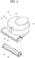
- FIG. 4 is a conceptual view showing the cleaner body 110 of FIG. 1 , and the supporting member 130 and the brush module 140 separated from the cleaner body 110.
- the supporting member 130 is inserted and mounted to the module mounting portion through the bottom part of the module mounting housing 112. And the supporting member 130 is separated and withdrawn from the module mounting portion through the bottom part of the module mounting housing 112.
- the brush module 140 is coupled to the supporting member 130, if the supporting member 130 is inserted and mounted to the module mounting portion, the brush module 140 is also inserted and mounted to the module mounting portion together with the supporting member 130. Likewise, if the supporting member 130 is separated and withdrawn from the module mounting portion, the brush module 140 is also separated and withdrawn from the module mounting portion together with the supporting member 130.
- the supporting member 130 and the brush module 140 are inserted and mounted to the module mounting portion in upper and lower directions. Accordingly, if the supporting member 130 and the brush module 140 are separated from the module mounting portion, they may be withdrawn from the module mounting portion by their weight without an external force.
- the brush module 140 is detachably coupled to the cleaner body 110 in a state that the supporting member 130 rotatably supports the brush module 140.
- the brush module 140 may be directly detachably coupled to the cleaner body 110 without the supporting member 130.
- a structure corresponding to the supporting member 130 may be provided at the module mounting portion of the cleaner body 110.
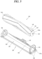
- FIG. 5 is a disassembled perspective view of the supporting member 130 and the brush module 140 shown in FIG. 4 .
- the supporting member 130 is formed to rotatably support the brush module 140.
- the supporting member 130 includes a first supporting portion 131, a second supporting portion 132, the first connection portion 133, and the second connection portion 134.
- the first and second supporting portions 131,132 enclose both ends of the rotation rod 141 so as to support the brush module 140 in a relatively rotatable manner. More specifically, the first supporting portion 131 encloses one end of the rotation rod 141, and the second supporting portion 132 encloses another end of the rotation rod 141.
- the hook 136 protrudes from an outer side surface of the first supporting portion 131. Once the supporting member 130 is inserted into the module mounting portion, the hook 136 is locked by a protrusion (not shown) formed on an inner side surface of the module mounting portion. With such a configuration, the hook 136 prevents any separation of the supporting member 130.
- a protruding portion 137 protruding in an insertion direction of the supporting member 130 is formed at a rear side of the second connection portion 134.
- the protruding portion 137 protrudes towards the inside of the module mounting portion.
- a groove (not shown) corresponding to the protruding portion 137 is formed on an inner side surface of the module mounting portion, and the protruding portion 137 is inserted into the groove.
- the protruding portion 137 protrudes in an insertion direction of the supporting member 130, and a moving direction of the robot cleaner crosses the insertion direction. Accordingly, the protruding portion 137 may fix a position of the second connection portion 134 by preventing a movement of the second connection portion 134 in right and left directions and in upper and lower directions. This may prevent damage of the second connection portion 134.
- the brush module 140 includes the rotation rod 141 and the brush 142.
- the rotation brush 141 is formed to extend in one direction.
- a rotation shaft of the rotation rod 141 may be disposed to be perpendicular to a forward driving direction of the cleaner body 110.
- the rotation rod 141 is configured to be connected to a rotation driving portion 110b (refer to FIG. 7 ) when mounted to the cleaner body 110, and to be rotatable in at least one direction.
- a rotation coupling member 141a is provided at one end of the rotation rod 141.
- the rotation coupling member 141a is exposed to the outside through one end of the rotation rod 141 in an axial direction.
- the rotation coupling member 141a is coupled to the rotation driving portion 110b (refer to FIG. 7 ). With such a configuration, when the rotation driving portion 110b is driven, the rotation coupling member 141a transmits a driving force to the rotation rod 141 from the rotation driving portion 110b.
- the separation distance between the first and second supporting portions 131, 132 is equal to the length of the rotation rod 141, it may be difficult to couple the brush module 140 to the supporting member 130 due to the rotation coupling member 141a.
- the reason is because the rotation coupling member 141a protrudes from one end of the rotation rod 141.
- the rotation coupling member 141a can be pressurized, a difficulty in coupling the brush module 140 and the supporting member 130 with each other may be solved.
- a rotation supporting portion 141c is installed at another end of the rotation rod 141.
- the rotation supporting portion 141c may have an outer circumferential surface formed as a curved surface so as to be rotatable in a restricted state to the second supporting portion 132 of the supporting member 130.
- the rotation supporting portion 141c may include a bearing 141c' (refer to FIG. 7 ).
- the rotation supporting portion 141c is supported by the second supporting portion 132 of the supporting member 130 so as to be relatively rotatable. More specifically, the outer circumferential surface of the rotation supporting portion 141c is enclosed by the second supporting portion 132. As the rotation supporting portion 141c is supported by the second supporting portion 132, the rotation shaft of the rotation rod 141 may be disposed to be aligned with a rotation shaft of the rotation driving portion 110b.
- a rotation supporting portion for rotatably supporting the rotation rod 141 may be additionally formed at the module mounting portion 110a.
- the rotation rod 141 may be rotatably mounted to the supporting member 130.
- the first supporting portion 131 is provided with a through hole for inserting the rotation rod 141, and the rotation coupling member 141a protrudes from one end of the rotation rod 141 exposed to the outside via the through hole.
- the brush 142 is coupled to an outer circumferential surface of the rotation rod 141.
- a groove 141' is formed at the outer circumferential surface of the rotation rod 141, and the brush 142 may be inserted into the groove 141' in a lengthwise direction of the rotation rod 141.
- the rotation driving portion 110b (refer to FIG. 7 ) is provided with the contact switch 110c at a contact position with the contact terminal 143. Accordingly, if the brush module 140 is mounted to the cleaner body 110 (refer to FIG. 1 ), the rotation coupling member 141a of the rotation rod 141 is inserted into the rotation driving portion 110b. And the contact terminal 143 formed on the surface of the rotation coupling member 141a naturally contacts the contact switch. The reason is because the rotation coupling member 141a receives an elastic force from the elastic member 141b (refer to FIG. 7 ).
- the controller of the robot cleaner may recognize a type of the cleaning module mounted to the module mounting portion, according to the number of the contact terminal 143 contacting the contact switch. For instance, FIG. 5 shows that the contact terminal 143 is provided in 3 in number, and FIG. 6 to be explained later shows that a contact terminal 153 is provided in 2 in number. Accordingly, if the number of the contact terminal contacting the contact switch is 3, the controller may recognize the cleaning module as the brush module 140. On the other hand, if the number of the contact terminal contacting the contact switch is 2, the controller may recognize the cleaning module as the mop module 150 (refer to FIG. 6 ).
- the mop module will be explained as another example of the cleaning module.
- Water discharge openings 151f communicated with the water accommodating portion 151d are formed on an outer circumference of the rotation rod 151. Water filled in the water accommodating portion 151d is discharged out through the water discharge openings 151f.
- the rotation rod 151 of the mop module 150 is provided with the contact terminal 153 on the same position as the rotation rod 141 of the brush module 140.
- the number of the contact terminals 153 provided at the rotation rod 151 of the mop module 150 is different from the number of the contact terminals 143 provided at the rotation rod 141 of the brush module. The reason is because the controller of the robot cleaner recognizes a type of the cleaning module based on the number of the contact terminal 153 contacting the contact switch 110c (refer to FIG. 7 ), which is explained with reference to the aforementioned FIG. 5 .
- An inclined surface 110d is formed at an inlet of the module mounting portion 110a.
- the position of the inclined surface 110d is a contact position with the rotation coupling member 141a in a process of mounting the brush module 140. Accordingly, in the process of mounting the brush module 140, the rotation coupling member 141a may slide along the inclined surface 1 10d to thus be pressurized towards the inside of the rotation rod 141.
- the hook coupling portion 138 includes a first part 138a, a second part 138b, a locking protrusion 138c and a manipulation portion 138d.
- the inclined surface 138c1 contacts the protrusion 110e during an insertion process of the supporting member 130, and is formed to be slidable along the surface of the protrusion 110e. With such a configuration, the inclined surface 138c1 contacts the protrusion 110e and passes through the protrusion 110e during an insertion process of the supporting member 130.
- the rotation coupling member 141a of the rotation rod 141 contacts the inclined surface 110d.
- the hook coupling portion 138 of the supporting member 130 contacts the protrusion 110e.
- the process of separating the brush module 140 from the cleaner body 110 may be understood to be opposite to the mounting process.
- the wheel cover 161c is formed to support the motor 161b.
- a space (not shown) for mounting the motor 161b is provided at the wheel cover 161c, and the motor 161b coupled to the main wheel 161a is inserted into the space.
- the sub connectors 161e, 161e', 161e” are configured to electrically connect various types of electronic components provided at the driving wheel 161 to the main connector 161f".
- Each of the sub connectors 161e, 161e', 161e” may include a cable (C) and a connection terminal (T).
- the cable (C) protrudes from the main connector 161f", and the connection terminal(T) is installed at the end of the cable (C).
- the wheel cover 161c may form an arrangement region of the cable (C), and may be provided with a cable holder (not shown) for fixing the cable (C).
- connection terminal 113a of the main PCB 113 is inserted into the main connector 161f' having a shape of a connection socket, resulting in electrically connecting the main PCB 113 to the driving wheel 161.
- the positions of the connection terminal 113a and the connection socket may be interchanged with each other.
- the coupling member (F) may be formed to couple the wheel cover 161c with the main housing 111.
- the main connector 112c of the module mounting housing 112 is also electrically connected to various electronic components of the module mounting housing 112 through a sub connector (not shown). If the module mounting housing 112 is mounted to the main housing 111, the main connector 112c of the module mounting housing 112 may be coupled to a connection terminal (not shown) of the main PCB 113.
- the driving wheel 161 the module mounting housing 112, or the like is physically coupled to the main housing 111, it is electrically connected to the main housing 111. This may facilitate an assembly between each module and the main housing 111, and may prevent a secondary inferiority by preventing an influence on other module or components when each module is disassembled from the main housing 111.
- the physical and electrical connection structure of the present invention is advantageous to a massive production by automation.
- a production process of a modernized robot cleaner is precisely performed by a robot which is operated mechanically, and a man's inaccurate intervention is excluded during the production process.
- an assembly between the main housing 111 and each module may be completed by a single automation process.
- the assembly means not only a physical connection, but also an electrical connection. Since the protruding direction of the main connector 161f" is the same as the insertion direction of the driving wheels 161, a physical coupling direction and an electrical coupling direction between modules may be understood to be the same. Accordingly, the structure of the present invention is very advantageous to an automation process excluding a man's intervention.
- Reference numeral 111b denotes a switch cover, and a power switch structure of the robot cleaner will be explained hereinafter.
- FIGS. 13 and 14 are conceptual views partially showing appearance of the main housing 111 to which the switch cover 111b is exposed
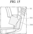
- FIG. 15 is a sectional view showing an inner structure of a power switch 111c and the switch cover 111b.
- the robot cleaner performs an autonomous cleaning operation while moving on a predetermined region according to a preset algorithm, it is not preferable to protrude a specific part of the switch cover 111b from the main housing 111. For instance, if the switch cover 11 1b protrudes from the main housing 111 excessively, the switch cover 111b may be locked to an object such as a wall or a door, while the robot cleaner is moving.
Landscapes
- Engineering & Computer Science (AREA)
- Mechanical Engineering (AREA)
- Nozzles For Electric Vacuum Cleaners (AREA)
- Electric Vacuum Cleaner (AREA)
Claims (12)
- Reinigungsvorrichtung (100), die Folgendes umfasst:einen Reinigungsvorrichtungskörper (110), der einen Modulmontageabschnitt (110a) aufweist;einen Drehantriebsabschnitt (110b), der an einer Seite des Modulmontageabschnitts (110a) vorgesehen ist;ein Tragelement (130), das durch einen unteren Teil des Reinigungsvorrichtungskörpers in den Modulmontageabschnitt (110a) eingesetzt und daran montiert ist und von dem Modulmontageabschnitt (110a) getrennt und daraus herausgezogen wird; undein Reinigungsmodul (120), das an das Tragelement (130) gekoppelt wird, um zusammen mit dem Tragelement (130) eingesetzt oder herausgezogen zu werden, wenn das Tragelement (130) eingesetzt oder herausgezogen wird,wobei das Reinigungsmodul (120) Folgendes enthält:einen Drehstab (141), der durch das Tragelement (130) drehbar getragen wird und an den Drehantriebsabschnitt (110b) gekoppelt wird, indem er in den Modulmontageabschnitt (110a) eingesetzt wird; undein Reinigungselement, das an eine Außenumfangsfläche des Drehstabs (141) gekoppelt ist und konfiguriert ist, einen Boden zu reinigen, indem es zusammen mit dem Drehstab (141) gedreht wird, wenn der Drehstab (141) durch eine Drehantriebskraft, die von dem Drehantriebsabschnitt (110b) übermittelt wird, gedreht wird;dadurch gekennzeichnet, dass der Drehstab (141) Folgendes enthält:ein Drehkopplungselement (141a), das durch ein Ende des Drehstabs (141) in einer axialen Richtung nach außen zeigt und derart gebildet ist, dass es in Richtung der Innenseite der Rotationsstange mit Druck beaufschlagt wird; undein elastisches Element (141b), das konfiguriert ist, eine elastische Kraft derart bereitzustellen, dass das Drehkopplungselement (141a), das in Richtung der Innenseite der Rotationsstange mit Druck beaufschlagt wird, in eine Anfangsposition zurückgebracht wird,wobei der Modulmontageabschnitt (110a) eine geneigte Oberfläche (110d) enthält, die an einer Kontaktposition mit dem Drehkopplungselement (141a) gebildet ist, während das Reinigungsmodul (120) derart montiert ist, dass das Drehkopplungselement (141a) auf einer schrägen Oberfläche gleitet, wobei die geneigte Oberfläche (110d) konfiguriert ist, das Drehkopplungselement (141a) in Richtung der Innenseite der Rotationsstange (141) allmählich mit Druck zu beaufschlagen, während das Reinigungsmodul (120) montiert wird.
- Reinigungsvorrichtung (100) nach Anspruch 1, wobei die geneigte Oberfläche (110d) derart gebildet ist, dass sie sich näher an dem Drehkopplungselement (141a) befindet, wenn sie sich in Richtung der Innenseite des Modulmontageabschnitts (110a) befindet.
- Reinigungsvorrichtung nach Anspruch 1, wobei der Drehantriebsabschnitt (110b) derart gebildet ist, dass er das Drehkopplungselement (141a) darin aufnimmt, und
wobei in einem Zustand, in dem das Reinigungsmodul (120) an dem Modulmontageabschnitt (110a) montiert ist, das Drehkopplungselement (141a) durch eine elastische Kraft, die von dem elastischen Element (141b) bereitgestellt wird, mit Druck beaufschlagt wird, um so in den Drehantriebsabschnitt (110b) eingesetzt zu werden. - Reinigungsvorrichtung (100) nach Anspruch 1, wobei der Drehantriebsabschnitt (110b) derart gebildet ist, dass er das Drehkopplungselement (141a) darin aufnimmt, und
wobei das Drehkopplungselement (141a), während das Reinigungsmodul (120) montiert wird, nacheinander die geneigte Oberfläche (110d) und eine innere Ebene des Modulmontageabschnitts (110a) durchläuft, und dann durch eine elastische Kraft, die von dem elastischen Element bereitgestellt wird, um so in den Drehantriebsabschnitt (110b) eingesetzt zu werden, auf eine anfängliche Position zurückgebracht wird. - Reinigungsvorrichtung (100) nach Anspruch 1, wobei das Tragelement (130) Folgendes enthält:einen ersten Tragabschnitt (131), der ein Ende des Drehstabs (141) umschließt, um den Drehstab (141) relativ drehbar zu tragen, und einen zweiten Tragabschnitt (132), der ein anderes Ende des Drehstabs (141) umschließt; undeinen ersten Verbindungsabschnitt (133) und einen zweiten Verbindungsabschnitt (134), die voneinander beabstandet sind, und konfiguriert sind, den ersten und den zweiten Tragabschnitt miteinander zu verbinden, undwobei das Reinigungselement zu einem Raum zwischen dem ersten und zweiten Verbindungsabschnitt (133, 134) hin frei liegt, um einen Boden zu reinigen.
- Reinigungsvorrichtung (100) nach Anspruch 5, wobei der Modulmontageabschnitt (110a) mit einem Vorsprung (110e) versehen ist, der in Richtung des Tragelements (130) vorsteht, und
wobei das Tragelement (130) mit einem Hakenkopplungsabschnitt (138) versehen ist, um zu verhindern, dass es von dem Modulmontageabschnitt (110a) getrennt wird. - Reinigungsvorrichtung (100) nach Anspruch 6, wobei der Hakenkopplungsabschnitt (138) Folgendes enthält:einen ersten Teil (138a), der von einem Ende des Tragelements (130) in Richtung der Innenseite des Modulmontageabschnitts (110a) vorsteht;einen zweiten Teil (138b), der von dem ersten Teil (138a) gebogen ist und in Richtung der Außenseite des Modulmontageabschnitts (110a) vorsteht;einen Handhabungsabschnitt (138d), der von einem Ende des zweiten Teils (138b) vorsteht, um den Hakenkopplungsabschnitt (138) handzuhaben; undeinen Verriegelungsvorsprung (138c), der von einem mittleren Bereich des zweiten Teils (138b) in Richtung des Vorsprungs (110e) vorsteht, um mit dem Vorsprung (110e) verriegelt zu werden, wenn das Tragelement (130) in den Modulmontageabschnitt (110a) eingesetzt wird.
- Reinigungsvorrichtung (100) nach Anspruch 7, wobei der Verriegelungsvorsprung (138c) Folgendes enthält:eine geneigte Oberfläche (138c1), die den Vorsprung (110e) berührt, während das Tragelement (130) eingesetzt wird, und gebildet ist, um entlang einer Oberfläche des Vorsprungs (110e) gleiten zu können; undeine Verriegelungsoberfläche (138c2), die an einer der geneigten Oberfläche (138c1) gegenüberliegenden Seite gebildet ist, und derart gebildet ist, dass sie den Vorsprung (110e) in einem Zustand, in dem das Tragelement (130) an dem Modulmontageabschnitt (110a) montiert ist, berührt.
- Reinigungsvorrichtung (100) nach Anspruch 7, wobei in einem Zustand, in dem das Tragelement (130) an dem Modulmontageabschnitt (110a) montiert ist, der Handhabungsabschnitt (138d) von dem Reinigungsvorrichtungskörper (110) beabstandet ist, um in Richtung des Reinigungsvorrichtungskörpers (110) mit Druck beaufschlagt zu werden.
- Reinigungsvorrichtung (100) nach Anspruch 9, wobei dann, wenn der Handhabungsabschnitt (138d) in einer axialen Richtung des Drehstabs (141) mit Druck beaufschlagt wird, ein gekoppelter Zustand zwischen dem Vorsprung (110e) und dem Verriegelungsvorsprung (138c) gelöst wird.
- Reinigungsvorrichtung (100) nach Anspruch 9, wobei der Hakenkopplungsabschnitt (138) ein einer dem Drehkopplungselement (141a) gegenüberliegenden Seite gebildet ist, und
wobei dann, wenn ein gekoppelter Zustand zwischen dem Vorsprung (110e) und dem Verriegelungsvorsprung (138c) gelöst wird, das Tragelement (130) und das Reinigungsmodul (120) auf der Grundlage des Drehkopplungselements (141a) verkippt werden, um so von dem Modulmontageabschnitt (110a) getrennt zu werden. - Reinigungsvorrichtung (100) nach Anspruch 1, wobei das Reinigungsmodul (120) ein Reinigungsmodul (140) vom ersten Typ und ein Reinigungsmodul (150) vom zweiten Typ enthält, die wahlweise an das Tragelement (130) montiert werden können,wobei ein Drehstab (141) des Reinigungsmoduls (140) vom ersten Typ und ein Drehstab des Reinigungsmoduls (150) vom zweiten Typ an derselben Position mit einer unterschiedlichen Zahl von Kontaktanschlüssen (143, 153) versehen sind,wobei der Drehantriebsabschnitt (110b) an einer Kontaktposition mit dem Kontaktanschluss (143, 153) mit einem Kontaktschalter (110c) versehen ist, undwobei eine Steuereinrichtung der Reinigungsvorrichtung (100) einen Typ des Reinigungsmoduls (120), das an dem Modulmontageabschnitt (110a) montiert ist, entsprechend der Zahl der Kontaktanschlüsse (143, 153), die den Kontaktschalter (110c) berühren, erkennt und einen Reinigungsalgorithmus der Reinigungsvorrichtung (100) basierend auf dem erkannten Typ des Reinigungsmoduls (120) auswählt.
Applications Claiming Priority (3)
| Application Number | Priority Date | Filing Date | Title |
|---|---|---|---|
| KR1020160184433 | 2016-12-30 | ||
| KR1020170134162A KR101961664B1 (ko) | 2017-10-16 | 2017-10-16 | 청소기 |
| PCT/KR2017/014559 WO2018124543A1 (ko) | 2016-12-30 | 2017-12-12 | 청소기 |
Publications (3)
| Publication Number | Publication Date |
|---|---|
| EP3536211A1 EP3536211A1 (de) | 2019-09-11 |
| EP3536211A4 EP3536211A4 (de) | 2020-07-22 |
| EP3536211B1 true EP3536211B1 (de) | 2024-07-10 |
Family
ID=62709177
Family Applications (2)
| Application Number | Title | Priority Date | Filing Date |
|---|---|---|---|
| EP17888909.3A Active EP3536211B1 (de) | 2016-12-30 | 2017-12-12 | Reiniger |
| EP17886726.3A Active EP3563747B1 (de) | 2016-12-30 | 2017-12-12 | Roboterreiniger |
Family Applications After (1)
| Application Number | Title | Priority Date | Filing Date |
|---|---|---|---|
| EP17886726.3A Active EP3563747B1 (de) | 2016-12-30 | 2017-12-12 | Roboterreiniger |
Country Status (6)
| Country | Link |
|---|---|
| US (1) | US10568482B2 (de) |
| EP (2) | EP3536211B1 (de) |
| CN (2) | CN110099596B (de) |
| AU (1) | AU2017385735B2 (de) |
| TW (1) | TWI657788B (de) |
| WO (1) | WO2018124543A1 (de) |
Families Citing this family (13)
| Publication number | Priority date | Publication date | Assignee | Title |
|---|---|---|---|---|
| GB2577888B (en) * | 2018-10-08 | 2021-09-08 | Dyson Technology Ltd | A cleaner head |
| CN109645893B (zh) | 2018-12-28 | 2021-07-06 | 云鲸智能科技(东莞)有限公司 | 一种清洁机器人 |
| USD947474S1 (en) * | 2019-08-28 | 2022-03-29 | Lg Electronics Inc. | Robotic vacuum cleaner |
| USD938677S1 (en) * | 2019-08-28 | 2021-12-14 | Lg Electronics Inc. | Robotic vacuum cleaner |
| USD935711S1 (en) * | 2019-08-28 | 2021-11-09 | Lg Electronics Inc. | Robotic vacuum cleaner |
| USD943227S1 (en) * | 2019-08-28 | 2022-02-08 | Lg Electronics Inc. | Robotic vacuum cleaner |
| FR3104018B1 (fr) * | 2019-12-09 | 2021-12-31 | Seb Sa | Tête de nettoyage équipée d’un élément de nettoyage amovible |
| USD1061840S1 (en) | 2020-11-27 | 2025-02-11 | Avalon Biomedical (Management) Limited | Air disinfection and sanitization device |
| CN115916268A (zh) * | 2020-01-26 | 2023-04-04 | 铠耀生物医药科技(管理)有限公司 | 消毒系统 |
| ES2875226A1 (es) * | 2020-05-04 | 2021-11-08 | Cecotec Res And Development | Aparato autonomo de limpieza de superficies con sistema de deteccion de rodillo central |
| CN111973083B (zh) * | 2020-08-27 | 2025-11-18 | 苏州三六零机器人科技有限公司 | 扫地机 |
| CN112197363A (zh) * | 2020-08-28 | 2021-01-08 | 南京涵铭置智能科技有限公司 | 一种智能空气净化设备及净化方法 |
| SE2250268A1 (en) * | 2022-02-28 | 2023-08-29 | Husqvarna Ab | Self-propelled Robotic Work Tool |
Family Cites Families (35)
| Publication number | Priority date | Publication date | Assignee | Title |
|---|---|---|---|---|
| US3790987A (en) * | 1972-10-20 | 1974-02-12 | Scott & Fetzer Co | Drive means for vacuum cleaner |
| CH663140A5 (de) * | 1982-04-21 | 1987-11-30 | Karl Weber | Behaelter zur aufnahme von gebrauchsgegenstaenden. |
| SE504223C2 (sv) * | 1995-04-26 | 1996-12-09 | Electrolux Ab | Anordning vid ett borstmunstycke för en dammsugare |
| TW321597B (en) * | 1996-07-09 | 1997-12-01 | Sanyo Electric Co | The sucking device for electric vacuum cleaner |
| DE19728380C1 (de) * | 1997-07-03 | 1999-01-14 | Kaercher Gmbh & Co Alfred | Bürstenwalze für ein Reinigungsgerät |
| DE19805900C1 (de) * | 1998-02-13 | 1999-07-29 | Duepro Ag | Saugreinigungswerkzeug mit ausschwenkbarer Bürstenwalze |
| DE19820628C1 (de) * | 1998-05-08 | 1999-09-23 | Kaercher Gmbh & Co Alfred | Kehrmaschine |
| KR100507928B1 (ko) * | 2003-07-24 | 2005-08-17 | 삼성광주전자 주식회사 | 로봇청소기 |
| GB2413942B (en) * | 2004-05-13 | 2007-07-18 | Dyson Ltd | Tool for a surface treating appliance |
| ES2346343T3 (es) | 2005-02-18 | 2010-10-14 | Irobot Corporation | Robot autonomo de limpieza de superficies para una limpieza en seco y en mojado. |
| KR100738886B1 (ko) * | 2005-10-26 | 2007-07-12 | 엘지전자 주식회사 | 청소용 이동로봇의 청소모듈 |
| EP2829939B1 (de) | 2005-12-02 | 2019-11-13 | iRobot Corporation | Roboternavigationssystem mit autonomer Abdeckung |
| US8584305B2 (en) | 2005-12-02 | 2013-11-19 | Irobot Corporation | Modular robot |
| KR101300492B1 (ko) | 2005-12-02 | 2013-09-02 | 아이로보트 코퍼레이션 | 커버리지 로봇 이동성 |
| EP2816434A3 (de) | 2005-12-02 | 2015-01-28 | iRobot Corporation | Roboter mit autonomem Wirkungsbereich |
| KR101457423B1 (ko) | 2008-06-17 | 2014-11-06 | 삼성전자주식회사 | 유량감지 유닛 및 그것을 구비한 청소장치 |
| KR101573742B1 (ko) * | 2010-10-25 | 2015-12-07 | 삼성전자주식회사 | 로봇청소기 |
| CN202076369U (zh) * | 2011-05-19 | 2011-12-14 | 中航锂电(洛阳)有限公司 | 一种锂电池防护盖及使用该防护盖的锂电池 |
| WO2013106762A2 (en) * | 2012-01-13 | 2013-07-18 | Kent Research Corporation | Surface cleaning machines and methods of use |
| GB2499213B (en) * | 2012-02-08 | 2016-10-19 | Dyson Technology Ltd | A cleaner-head for a vacuum cleaner |
| KR20150048490A (ko) * | 2013-10-28 | 2015-05-07 | 삼성전자주식회사 | 로봇청소기 |
| CN204049513U (zh) * | 2014-03-25 | 2014-12-31 | 莱克电气股份有限公司 | 多功能吸尘器地刷 |
| CN204091891U (zh) * | 2014-07-11 | 2015-01-14 | 刘向前 | 一种智能扫地机 |
| KR20160023120A (ko) | 2014-08-21 | 2016-03-03 | 삼성전자주식회사 | 로봇 청소기 |
| CN204133378U (zh) * | 2014-08-21 | 2015-02-04 | 深圳市宝乐机器人技术有限公司 | 一种在智能扫地机上具有多种清洁方式的装置 |
| CN104172993B (zh) * | 2014-08-21 | 2018-01-16 | 广东宝乐机器人股份有限公司 | 一种在智能扫地机上具有多种清洁方式的方法及其装置 |
| EP2992800B1 (de) * | 2014-09-03 | 2017-11-01 | Samsung Electronics Co., Ltd. | Staubsauger |
| CN104224059B (zh) * | 2014-09-09 | 2016-06-08 | 东南大学 | 一种室内近地除尘清洁装置 |
| KR102320204B1 (ko) | 2014-09-24 | 2021-11-02 | 삼성전자주식회사 | 로봇 청소기 및 이를 포함하는 로봇 청소기 시스템 |
| KR101641262B1 (ko) | 2014-12-01 | 2016-07-20 | 엘지전자 주식회사 | 로봇 청소기 |
| CN204436109U (zh) * | 2015-01-08 | 2015-07-01 | 温州云洁仓储设备有限公司 | 置物柜的易拆卸门体安装结构 |
| KR102452480B1 (ko) * | 2015-09-02 | 2022-10-11 | 삼성전자주식회사 | 진공 청소기 |
| CN205144443U (zh) * | 2015-11-04 | 2016-04-13 | 东莞市智科智能科技有限公司 | 清洁机器人 |
| CN205181246U (zh) * | 2015-11-23 | 2016-04-27 | 刘华 | 一种智能吸尘器 |
| CN105982611A (zh) | 2016-04-14 | 2016-10-05 | 北京小米移动软件有限公司 | 自主清洁设备 |
-
2017
- 2017-12-12 EP EP17888909.3A patent/EP3536211B1/de active Active
- 2017-12-12 AU AU2017385735A patent/AU2017385735B2/en active Active
- 2017-12-12 EP EP17886726.3A patent/EP3563747B1/de active Active
- 2017-12-12 WO PCT/KR2017/014559 patent/WO2018124543A1/ko not_active Ceased
- 2017-12-12 CN CN201780080171.1A patent/CN110099596B/zh active Active
- 2017-12-12 CN CN202111172023.7A patent/CN113854896B/zh active Active
- 2017-12-28 US US15/856,213 patent/US10568482B2/en active Active
- 2017-12-28 TW TW106146301A patent/TWI657788B/zh not_active IP Right Cessation
Also Published As
| Publication number | Publication date |
|---|---|
| CN113854896B (zh) | 2023-04-14 |
| AU2017385735A1 (en) | 2019-06-20 |
| WO2018124543A1 (ko) | 2018-07-05 |
| CN113854896A (zh) | 2021-12-31 |
| EP3563747A1 (de) | 2019-11-06 |
| CN110099596B (zh) | 2021-10-26 |
| EP3563747A4 (de) | 2020-03-04 |
| CN110099596A (zh) | 2019-08-06 |
| TWI657788B (zh) | 2019-05-01 |
| TW201828870A (zh) | 2018-08-16 |
| AU2017385735B2 (en) | 2021-03-25 |
| US10568482B2 (en) | 2020-02-25 |
| US20180184871A1 (en) | 2018-07-05 |
| EP3536211A4 (de) | 2020-07-22 |
| EP3563747B1 (de) | 2022-10-12 |
| EP3536211A1 (de) | 2019-09-11 |
Similar Documents
| Publication | Publication Date | Title |
|---|---|---|
| AU2017385735B2 (en) | Cleaner | |
| AU2017385736B2 (en) | Robot cleaner | |
| EP3245927B1 (de) | Reiniger | |
| EP2417894B1 (de) | Reinigungsroboter | |
| KR101223478B1 (ko) | 로봇청소기의 먼지통 착탈 감지 장치 | |
| EP2636350B1 (de) | Reiniger mit Bürstenwalze | |
| EP4241643A2 (de) | Reiniger | |
| KR102460609B1 (ko) | 청소기 | |
| EP4374761A2 (de) | Reinigungsstation | |
| KR100671897B1 (ko) | 스위치형 센서가 구비된 로봇 청소기 | |
| EP4085809B1 (de) | Vakuum-ladestation für roboter | |
| EP4023129B1 (de) | Reinigungseinheit mit rührer | |
| KR20080028219A (ko) | 분리형 로봇 청소기 | |
| KR102045462B1 (ko) | 로봇 청소기 | |
| EP3562368B1 (de) | Reiniger | |
| KR101208980B1 (ko) | 분리형 로봇 청소기 | |
| KR101961664B1 (ko) | 청소기 | |
| CN114173624A (zh) | 包括搅动器的清洁单元 | |
| CN121194730A (zh) | 吸尘器和吸尘器充电座 |
Legal Events
| Date | Code | Title | Description |
|---|---|---|---|
| STAA | Information on the status of an ep patent application or granted ep patent |
Free format text: STATUS: THE INTERNATIONAL PUBLICATION HAS BEEN MADE |
|
| PUAI | Public reference made under article 153(3) epc to a published international application that has entered the european phase |
Free format text: ORIGINAL CODE: 0009012 |
|
| STAA | Information on the status of an ep patent application or granted ep patent |
Free format text: STATUS: REQUEST FOR EXAMINATION WAS MADE |
|
| 17P | Request for examination filed |
Effective date: 20190607 |
|
| AK | Designated contracting states |
Kind code of ref document: A1 Designated state(s): AL AT BE BG CH CY CZ DE DK EE ES FI FR GB GR HR HU IE IS IT LI LT LU LV MC MK MT NL NO PL PT RO RS SE SI SK SM TR |
|
| AX | Request for extension of the european patent |
Extension state: BA ME |
|
| DAV | Request for validation of the european patent (deleted) | ||
| DAX | Request for extension of the european patent (deleted) | ||
| A4 | Supplementary search report drawn up and despatched |
Effective date: 20200623 |
|
| RIC1 | Information provided on ipc code assigned before grant |
Ipc: A47L 9/16 20060101AFI20200617BHEP |
|
| STAA | Information on the status of an ep patent application or granted ep patent |
Free format text: STATUS: EXAMINATION IS IN PROGRESS |
|
| 17Q | First examination report despatched |
Effective date: 20220512 |
|
| GRAP | Despatch of communication of intention to grant a patent |
Free format text: ORIGINAL CODE: EPIDOSNIGR1 |
|
| STAA | Information on the status of an ep patent application or granted ep patent |
Free format text: STATUS: GRANT OF PATENT IS INTENDED |
|
| INTG | Intention to grant announced |
Effective date: 20240220 |
|
| GRAS | Grant fee paid |
Free format text: ORIGINAL CODE: EPIDOSNIGR3 |
|
| GRAA | (expected) grant |
Free format text: ORIGINAL CODE: 0009210 |
|
| STAA | Information on the status of an ep patent application or granted ep patent |
Free format text: STATUS: THE PATENT HAS BEEN GRANTED |
|
| AK | Designated contracting states |
Kind code of ref document: B1 Designated state(s): AL AT BE BG CH CY CZ DE DK EE ES FI FR GB GR HR HU IE IS IT LI LT LU LV MC MK MT NL NO PL PT RO RS SE SI SK SM TR |
|
| REG | Reference to a national code |
Ref country code: CH Ref legal event code: EP |
|
| REG | Reference to a national code |
Ref country code: DE Ref legal event code: R096 Ref document number: 602017083277 Country of ref document: DE |
|
| REG | Reference to a national code |
Ref country code: LT Ref legal event code: MG9D |
|
| REG | Reference to a national code |
Ref country code: NL Ref legal event code: MP Effective date: 20240710 |
|
| PG25 | Lapsed in a contracting state [announced via postgrant information from national office to epo] |
Ref country code: PT Free format text: LAPSE BECAUSE OF FAILURE TO SUBMIT A TRANSLATION OF THE DESCRIPTION OR TO PAY THE FEE WITHIN THE PRESCRIBED TIME-LIMIT Effective date: 20241111 |
|
| REG | Reference to a national code |
Ref country code: AT Ref legal event code: MK05 Ref document number: 1701250 Country of ref document: AT Kind code of ref document: T Effective date: 20240710 |
|
| PG25 | Lapsed in a contracting state [announced via postgrant information from national office to epo] |
Ref country code: NL Free format text: LAPSE BECAUSE OF FAILURE TO SUBMIT A TRANSLATION OF THE DESCRIPTION OR TO PAY THE FEE WITHIN THE PRESCRIBED TIME-LIMIT Effective date: 20240710 |
|
| PG25 | Lapsed in a contracting state [announced via postgrant information from national office to epo] |
Ref country code: PT Free format text: LAPSE BECAUSE OF FAILURE TO SUBMIT A TRANSLATION OF THE DESCRIPTION OR TO PAY THE FEE WITHIN THE PRESCRIBED TIME-LIMIT Effective date: 20241111 Ref country code: NL Free format text: LAPSE BECAUSE OF FAILURE TO SUBMIT A TRANSLATION OF THE DESCRIPTION OR TO PAY THE FEE WITHIN THE PRESCRIBED TIME-LIMIT Effective date: 20240710 |
|
| PG25 | Lapsed in a contracting state [announced via postgrant information from national office to epo] |
Ref country code: NO Free format text: LAPSE BECAUSE OF FAILURE TO SUBMIT A TRANSLATION OF THE DESCRIPTION OR TO PAY THE FEE WITHIN THE PRESCRIBED TIME-LIMIT Effective date: 20241010 |
|
| PG25 | Lapsed in a contracting state [announced via postgrant information from national office to epo] |
Ref country code: FI Free format text: LAPSE BECAUSE OF FAILURE TO SUBMIT A TRANSLATION OF THE DESCRIPTION OR TO PAY THE FEE WITHIN THE PRESCRIBED TIME-LIMIT Effective date: 20240710 Ref country code: GR Free format text: LAPSE BECAUSE OF FAILURE TO SUBMIT A TRANSLATION OF THE DESCRIPTION OR TO PAY THE FEE WITHIN THE PRESCRIBED TIME-LIMIT Effective date: 20241011 Ref country code: PL Free format text: LAPSE BECAUSE OF FAILURE TO SUBMIT A TRANSLATION OF THE DESCRIPTION OR TO PAY THE FEE WITHIN THE PRESCRIBED TIME-LIMIT Effective date: 20240710 |
|
| PG25 | Lapsed in a contracting state [announced via postgrant information from national office to epo] |
Ref country code: BG Free format text: LAPSE BECAUSE OF FAILURE TO SUBMIT A TRANSLATION OF THE DESCRIPTION OR TO PAY THE FEE WITHIN THE PRESCRIBED TIME-LIMIT Effective date: 20240710 |
|
| PG25 | Lapsed in a contracting state [announced via postgrant information from national office to epo] |
Ref country code: LV Free format text: LAPSE BECAUSE OF FAILURE TO SUBMIT A TRANSLATION OF THE DESCRIPTION OR TO PAY THE FEE WITHIN THE PRESCRIBED TIME-LIMIT Effective date: 20240710 |
|
| PG25 | Lapsed in a contracting state [announced via postgrant information from national office to epo] |
Ref country code: IS Free format text: LAPSE BECAUSE OF FAILURE TO SUBMIT A TRANSLATION OF THE DESCRIPTION OR TO PAY THE FEE WITHIN THE PRESCRIBED TIME-LIMIT Effective date: 20241110 Ref country code: AT Free format text: LAPSE BECAUSE OF FAILURE TO SUBMIT A TRANSLATION OF THE DESCRIPTION OR TO PAY THE FEE WITHIN THE PRESCRIBED TIME-LIMIT Effective date: 20240710 |
|
| PG25 | Lapsed in a contracting state [announced via postgrant information from national office to epo] |
Ref country code: HR Free format text: LAPSE BECAUSE OF FAILURE TO SUBMIT A TRANSLATION OF THE DESCRIPTION OR TO PAY THE FEE WITHIN THE PRESCRIBED TIME-LIMIT Effective date: 20240710 |
|
| PG25 | Lapsed in a contracting state [announced via postgrant information from national office to epo] |
Ref country code: ES Free format text: LAPSE BECAUSE OF FAILURE TO SUBMIT A TRANSLATION OF THE DESCRIPTION OR TO PAY THE FEE WITHIN THE PRESCRIBED TIME-LIMIT Effective date: 20240710 Ref country code: RS Free format text: LAPSE BECAUSE OF FAILURE TO SUBMIT A TRANSLATION OF THE DESCRIPTION OR TO PAY THE FEE WITHIN THE PRESCRIBED TIME-LIMIT Effective date: 20241010 |
|
| PG25 | Lapsed in a contracting state [announced via postgrant information from national office to epo] |
Ref country code: RS Free format text: LAPSE BECAUSE OF FAILURE TO SUBMIT A TRANSLATION OF THE DESCRIPTION OR TO PAY THE FEE WITHIN THE PRESCRIBED TIME-LIMIT Effective date: 20241010 Ref country code: PL Free format text: LAPSE BECAUSE OF FAILURE TO SUBMIT A TRANSLATION OF THE DESCRIPTION OR TO PAY THE FEE WITHIN THE PRESCRIBED TIME-LIMIT Effective date: 20240710 Ref country code: NO Free format text: LAPSE BECAUSE OF FAILURE TO SUBMIT A TRANSLATION OF THE DESCRIPTION OR TO PAY THE FEE WITHIN THE PRESCRIBED TIME-LIMIT Effective date: 20241010 Ref country code: LV Free format text: LAPSE BECAUSE OF FAILURE TO SUBMIT A TRANSLATION OF THE DESCRIPTION OR TO PAY THE FEE WITHIN THE PRESCRIBED TIME-LIMIT Effective date: 20240710 Ref country code: IS Free format text: LAPSE BECAUSE OF FAILURE TO SUBMIT A TRANSLATION OF THE DESCRIPTION OR TO PAY THE FEE WITHIN THE PRESCRIBED TIME-LIMIT Effective date: 20241110 Ref country code: HR Free format text: LAPSE BECAUSE OF FAILURE TO SUBMIT A TRANSLATION OF THE DESCRIPTION OR TO PAY THE FEE WITHIN THE PRESCRIBED TIME-LIMIT Effective date: 20240710 Ref country code: GR Free format text: LAPSE BECAUSE OF FAILURE TO SUBMIT A TRANSLATION OF THE DESCRIPTION OR TO PAY THE FEE WITHIN THE PRESCRIBED TIME-LIMIT Effective date: 20241011 Ref country code: FI Free format text: LAPSE BECAUSE OF FAILURE TO SUBMIT A TRANSLATION OF THE DESCRIPTION OR TO PAY THE FEE WITHIN THE PRESCRIBED TIME-LIMIT Effective date: 20240710 Ref country code: ES Free format text: LAPSE BECAUSE OF FAILURE TO SUBMIT A TRANSLATION OF THE DESCRIPTION OR TO PAY THE FEE WITHIN THE PRESCRIBED TIME-LIMIT Effective date: 20240710 Ref country code: BG Free format text: LAPSE BECAUSE OF FAILURE TO SUBMIT A TRANSLATION OF THE DESCRIPTION OR TO PAY THE FEE WITHIN THE PRESCRIBED TIME-LIMIT Effective date: 20240710 Ref country code: AT Free format text: LAPSE BECAUSE OF FAILURE TO SUBMIT A TRANSLATION OF THE DESCRIPTION OR TO PAY THE FEE WITHIN THE PRESCRIBED TIME-LIMIT Effective date: 20240710 |
|
| REG | Reference to a national code |
Ref country code: DE Ref legal event code: R097 Ref document number: 602017083277 Country of ref document: DE |
|
| PG25 | Lapsed in a contracting state [announced via postgrant information from national office to epo] |
Ref country code: RO Free format text: LAPSE BECAUSE OF FAILURE TO SUBMIT A TRANSLATION OF THE DESCRIPTION OR TO PAY THE FEE WITHIN THE PRESCRIBED TIME-LIMIT Effective date: 20240710 Ref country code: SM Free format text: LAPSE BECAUSE OF FAILURE TO SUBMIT A TRANSLATION OF THE DESCRIPTION OR TO PAY THE FEE WITHIN THE PRESCRIBED TIME-LIMIT Effective date: 20240710 Ref country code: DK Free format text: LAPSE BECAUSE OF FAILURE TO SUBMIT A TRANSLATION OF THE DESCRIPTION OR TO PAY THE FEE WITHIN THE PRESCRIBED TIME-LIMIT Effective date: 20240710 |
|
| PG25 | Lapsed in a contracting state [announced via postgrant information from national office to epo] |
Ref country code: EE Free format text: LAPSE BECAUSE OF FAILURE TO SUBMIT A TRANSLATION OF THE DESCRIPTION OR TO PAY THE FEE WITHIN THE PRESCRIBED TIME-LIMIT Effective date: 20240710 |
|
| PG25 | Lapsed in a contracting state [announced via postgrant information from national office to epo] |
Ref country code: CZ Free format text: LAPSE BECAUSE OF FAILURE TO SUBMIT A TRANSLATION OF THE DESCRIPTION OR TO PAY THE FEE WITHIN THE PRESCRIBED TIME-LIMIT Effective date: 20240710 |
|
| PG25 | Lapsed in a contracting state [announced via postgrant information from national office to epo] |
Ref country code: IT Free format text: LAPSE BECAUSE OF FAILURE TO SUBMIT A TRANSLATION OF THE DESCRIPTION OR TO PAY THE FEE WITHIN THE PRESCRIBED TIME-LIMIT Effective date: 20240710 Ref country code: SK Free format text: LAPSE BECAUSE OF FAILURE TO SUBMIT A TRANSLATION OF THE DESCRIPTION OR TO PAY THE FEE WITHIN THE PRESCRIBED TIME-LIMIT Effective date: 20240710 |
|
| PLBE | No opposition filed within time limit |
Free format text: ORIGINAL CODE: 0009261 |
|
| STAA | Information on the status of an ep patent application or granted ep patent |
Free format text: STATUS: NO OPPOSITION FILED WITHIN TIME LIMIT |
|
| 26N | No opposition filed |
Effective date: 20250411 |
|
| PG25 | Lapsed in a contracting state [announced via postgrant information from national office to epo] |
Ref country code: MC Free format text: LAPSE BECAUSE OF FAILURE TO SUBMIT A TRANSLATION OF THE DESCRIPTION OR TO PAY THE FEE WITHIN THE PRESCRIBED TIME-LIMIT Effective date: 20240710 |
|
| REG | Reference to a national code |
Ref country code: CH Ref legal event code: PL |
|
| PG25 | Lapsed in a contracting state [announced via postgrant information from national office to epo] |
Ref country code: LU Free format text: LAPSE BECAUSE OF NON-PAYMENT OF DUE FEES Effective date: 20241212 |
|
| GBPC | Gb: european patent ceased through non-payment of renewal fee |
Effective date: 20241212 |
|
| PG25 | Lapsed in a contracting state [announced via postgrant information from national office to epo] |
Ref country code: SE Free format text: LAPSE BECAUSE OF FAILURE TO SUBMIT A TRANSLATION OF THE DESCRIPTION OR TO PAY THE FEE WITHIN THE PRESCRIBED TIME-LIMIT Effective date: 20240710 |
|
| REG | Reference to a national code |
Ref country code: BE Ref legal event code: MM Effective date: 20241231 |
|
| PG25 | Lapsed in a contracting state [announced via postgrant information from national office to epo] |
Ref country code: GB Free format text: LAPSE BECAUSE OF NON-PAYMENT OF DUE FEES Effective date: 20241212 Ref country code: BE Free format text: LAPSE BECAUSE OF NON-PAYMENT OF DUE FEES Effective date: 20241231 |
|
| PG25 | Lapsed in a contracting state [announced via postgrant information from national office to epo] |
Ref country code: FR Free format text: LAPSE BECAUSE OF NON-PAYMENT OF DUE FEES Effective date: 20241231 |
|
| PG25 | Lapsed in a contracting state [announced via postgrant information from national office to epo] |
Ref country code: CH Free format text: LAPSE BECAUSE OF NON-PAYMENT OF DUE FEES Effective date: 20241231 |
|
| PG25 | Lapsed in a contracting state [announced via postgrant information from national office to epo] |
Ref country code: IE Free format text: LAPSE BECAUSE OF NON-PAYMENT OF DUE FEES Effective date: 20241212 |
|
| PGFP | Annual fee paid to national office [announced via postgrant information from national office to epo] |
Ref country code: DE Payment date: 20251105 Year of fee payment: 9 |
|
| PG25 | Lapsed in a contracting state [announced via postgrant information from national office to epo] |
Ref country code: CY Free format text: LAPSE BECAUSE OF FAILURE TO SUBMIT A TRANSLATION OF THE DESCRIPTION OR TO PAY THE FEE WITHIN THE PRESCRIBED TIME-LIMIT Effective date: 20240710 |