EP3536274B1 - Dispositif de thérapie thermique haute fréquence - Google Patents
Dispositif de thérapie thermique haute fréquence Download PDFInfo
- Publication number
- EP3536274B1 EP3536274B1 EP17867185.5A EP17867185A EP3536274B1 EP 3536274 B1 EP3536274 B1 EP 3536274B1 EP 17867185 A EP17867185 A EP 17867185A EP 3536274 B1 EP3536274 B1 EP 3536274B1
- Authority
- EP
- European Patent Office
- Prior art keywords
- electrode
- terminal
- bridge
- passive
- active
- Prior art date
- Legal status (The legal status is an assumption and is not a legal conclusion. Google has not performed a legal analysis and makes no representation as to the accuracy of the status listed.)
- Active
Links
Images




Classifications
-
- A—HUMAN NECESSITIES
- A61—MEDICAL OR VETERINARY SCIENCE; HYGIENE
- A61B—DIAGNOSIS; SURGERY; IDENTIFICATION
- A61B18/00—Surgical instruments, devices or methods for transferring non-mechanical forms of energy to or from the body
- A61B18/04—Surgical instruments, devices or methods for transferring non-mechanical forms of energy to or from the body by heating
- A61B18/12—Surgical instruments, devices or methods for transferring non-mechanical forms of energy to or from the body by heating by passing a current through the tissue to be heated, e.g. high-frequency current
- A61B18/14—Probes or electrodes therefor
- A61B18/1492—Probes or electrodes therefor having a flexible, catheter-like structure, e.g. for heart ablation
-
- A—HUMAN NECESSITIES
- A61—MEDICAL OR VETERINARY SCIENCE; HYGIENE
- A61B—DIAGNOSIS; SURGERY; IDENTIFICATION
- A61B18/00—Surgical instruments, devices or methods for transferring non-mechanical forms of energy to or from the body
-
- A—HUMAN NECESSITIES
- A61—MEDICAL OR VETERINARY SCIENCE; HYGIENE
- A61B—DIAGNOSIS; SURGERY; IDENTIFICATION
- A61B18/00—Surgical instruments, devices or methods for transferring non-mechanical forms of energy to or from the body
- A61B18/04—Surgical instruments, devices or methods for transferring non-mechanical forms of energy to or from the body by heating
- A61B18/12—Surgical instruments, devices or methods for transferring non-mechanical forms of energy to or from the body by heating by passing a current through the tissue to be heated, e.g. high-frequency current
- A61B18/1206—Generators therefor
-
- A—HUMAN NECESSITIES
- A61—MEDICAL OR VETERINARY SCIENCE; HYGIENE
- A61B—DIAGNOSIS; SURGERY; IDENTIFICATION
- A61B18/00—Surgical instruments, devices or methods for transferring non-mechanical forms of energy to or from the body
- A61B18/04—Surgical instruments, devices or methods for transferring non-mechanical forms of energy to or from the body by heating
- A61B18/12—Surgical instruments, devices or methods for transferring non-mechanical forms of energy to or from the body by heating by passing a current through the tissue to be heated, e.g. high-frequency current
- A61B18/14—Probes or electrodes therefor
-
- A—HUMAN NECESSITIES
- A61—MEDICAL OR VETERINARY SCIENCE; HYGIENE
- A61B—DIAGNOSIS; SURGERY; IDENTIFICATION
- A61B18/00—Surgical instruments, devices or methods for transferring non-mechanical forms of energy to or from the body
- A61B2018/00005—Cooling or heating of the probe or tissue immediately surrounding the probe
-
- A—HUMAN NECESSITIES
- A61—MEDICAL OR VETERINARY SCIENCE; HYGIENE
- A61B—DIAGNOSIS; SURGERY; IDENTIFICATION
- A61B18/00—Surgical instruments, devices or methods for transferring non-mechanical forms of energy to or from the body
- A61B2018/00571—Surgical instruments, devices or methods for transferring non-mechanical forms of energy to or from the body for achieving a particular surgical effect
- A61B2018/00577—Ablation
-
- A—HUMAN NECESSITIES
- A61—MEDICAL OR VETERINARY SCIENCE; HYGIENE
- A61B—DIAGNOSIS; SURGERY; IDENTIFICATION
- A61B18/00—Surgical instruments, devices or methods for transferring non-mechanical forms of energy to or from the body
- A61B2018/00571—Surgical instruments, devices or methods for transferring non-mechanical forms of energy to or from the body for achieving a particular surgical effect
- A61B2018/00595—Cauterization
-
- A—HUMAN NECESSITIES
- A61—MEDICAL OR VETERINARY SCIENCE; HYGIENE
- A61B—DIAGNOSIS; SURGERY; IDENTIFICATION
- A61B18/00—Surgical instruments, devices or methods for transferring non-mechanical forms of energy to or from the body
- A61B2018/00636—Sensing and controlling the application of energy
- A61B2018/00696—Controlled or regulated parameters
- A61B2018/0072—Current
-
- A—HUMAN NECESSITIES
- A61—MEDICAL OR VETERINARY SCIENCE; HYGIENE
- A61B—DIAGNOSIS; SURGERY; IDENTIFICATION
- A61B18/00—Surgical instruments, devices or methods for transferring non-mechanical forms of energy to or from the body
- A61B2018/0091—Handpieces of the surgical instrument or device
- A61B2018/00916—Handpieces of the surgical instrument or device with means for switching or controlling the main function of the instrument or device
- A61B2018/00922—Handpieces of the surgical instrument or device with means for switching or controlling the main function of the instrument or device by switching or controlling the treatment energy directly within the hand-piece
-
- A—HUMAN NECESSITIES
- A61—MEDICAL OR VETERINARY SCIENCE; HYGIENE
- A61B—DIAGNOSIS; SURGERY; IDENTIFICATION
- A61B18/00—Surgical instruments, devices or methods for transferring non-mechanical forms of energy to or from the body
- A61B18/04—Surgical instruments, devices or methods for transferring non-mechanical forms of energy to or from the body by heating
- A61B18/12—Surgical instruments, devices or methods for transferring non-mechanical forms of energy to or from the body by heating by passing a current through the tissue to be heated, e.g. high-frequency current
- A61B18/1206—Generators therefor
- A61B2018/124—Generators therefor switching the output to different electrodes, e.g. sequentially
-
- A—HUMAN NECESSITIES
- A61—MEDICAL OR VETERINARY SCIENCE; HYGIENE
- A61B—DIAGNOSIS; SURGERY; IDENTIFICATION
- A61B18/00—Surgical instruments, devices or methods for transferring non-mechanical forms of energy to or from the body
- A61B18/04—Surgical instruments, devices or methods for transferring non-mechanical forms of energy to or from the body by heating
- A61B18/12—Surgical instruments, devices or methods for transferring non-mechanical forms of energy to or from the body by heating by passing a current through the tissue to be heated, e.g. high-frequency current
- A61B18/14—Probes or electrodes therefor
- A61B2018/1405—Electrodes having a specific shape
- A61B2018/1435—Spiral
-
- A—HUMAN NECESSITIES
- A61—MEDICAL OR VETERINARY SCIENCE; HYGIENE
- A61B—DIAGNOSIS; SURGERY; IDENTIFICATION
- A61B18/00—Surgical instruments, devices or methods for transferring non-mechanical forms of energy to or from the body
- A61B18/04—Surgical instruments, devices or methods for transferring non-mechanical forms of energy to or from the body by heating
- A61B18/12—Surgical instruments, devices or methods for transferring non-mechanical forms of energy to or from the body by heating by passing a current through the tissue to be heated, e.g. high-frequency current
- A61B18/14—Probes or electrodes therefor
- A61B2018/1405—Electrodes having a specific shape
- A61B2018/1435—Spiral
- A61B2018/1437—Spiral whereby the windings of the spiral touch each other such as to create a continuous surface
-
- A—HUMAN NECESSITIES
- A61—MEDICAL OR VETERINARY SCIENCE; HYGIENE
- A61B—DIAGNOSIS; SURGERY; IDENTIFICATION
- A61B18/00—Surgical instruments, devices or methods for transferring non-mechanical forms of energy to or from the body
- A61B18/04—Surgical instruments, devices or methods for transferring non-mechanical forms of energy to or from the body by heating
- A61B18/12—Surgical instruments, devices or methods for transferring non-mechanical forms of energy to or from the body by heating by passing a current through the tissue to be heated, e.g. high-frequency current
- A61B18/14—Probes or electrodes therefor
- A61B2018/1467—Probes or electrodes therefor using more than two electrodes on a single probe
-
- A—HUMAN NECESSITIES
- A61—MEDICAL OR VETERINARY SCIENCE; HYGIENE
- A61B—DIAGNOSIS; SURGERY; IDENTIFICATION
- A61B90/00—Instruments, implements or accessories specially adapted for surgery or diagnosis and not covered by any of the groups A61B1/00 - A61B50/00, e.g. for luxation treatment or for protecting wound edges
- A61B90/08—Accessories or related features not otherwise provided for
- A61B2090/0801—Prevention of accidental cutting or pricking
- A61B2090/08021—Prevention of accidental cutting or pricking of the patient or his organs
Definitions
- the present disclosure relates to a high-frequency thermal therapy device, and more particularly, to a high-frequency thermal therapy device capable of cauterizing a target lesion with an electrode inserted into a body.
- cancerous tissue, etc. in the body organ (liver, thyroid, etc.), it is treated by a surgical method and a non-surgical method.
- the non-surgical method is widely used as compared to the surgical method.
- transarterial chemoembolization percutaneous ethanol injection therapy, systemic anticancer chemotherapy, local thermal therapy, etc. are known, and among them, the local thermal therapy is the most effective method.
- the local thermal therapy includes high-frequency thermal therapy, microwave cauterization, laser cauterization, etc., and among them, the high-frequency thermal therapy is the most effective, such that physicians or patients have been much demanding the above-described method.
- Korean Patent Laid-Open Publication No. 10-2013-0128926 discloses a treatment device (hereinafter, referred to as a high-frequency thermal therapy device) used for the high-frequency thermal therapy.
- the conventional high-frequency thermal therapy device includes a radio frequency generator for generating a radio frequency current and an electrode for cauterizing a target lesion with the radio frequency current generated from the radio frequency generator.
- the conventional high-frequency thermal therapy device has the electrode inserted into the body to radiate a radio frequency energy, thereby cauterizing and necrotizing the target lesion such as a cancer tissue, or heats the target lesion of the blood vessel such as varicose veins to damage the intravenous wall and to cause fibrosis of the blood vessel, thereby removing swollen blood vessel.
- US 8 538 501 B2 discloses a switching assembly including four input terminals and four output terminals respectively connected to the four input terminals by four switches. That is, US 8 538 501 B2 discloses that a plurality of output terminals are connected to a plurality of input terminals by a plurality of switches, but fails to disclose or suggest a bridge selectively connects the input terminal to at least one of the plurality of output terminals so as to change a cauterization length of a target lesion.
- US 2015/196357 A1 discloses a multi-pole synchronous pulmonary artery radiofrequency ablation catheter.
- US 2002/111617 A1 discloses an adjustable trans-urethral radio-frequency ablation.
- US 6 129 724 A discloses systems and methods for forming elongated lesion patterns in body tissue using straight or curvilinear electrode elements.
- US 5 545 193 A discloses a helically wound radio-frequency emitting electrodes for creating lesions in body tissue.
- US 2013/096549 A1 discloses a method and apparatus for precisely controlling the size and shape of radio frequency ablations.
- EP 2 851 026 A1 discloses an overlapping bipolar electrode for high-frequency heat treatment.
- an object of the present disclosure is to provide a high-frequency thermal therapy device capable of adjusting the cauterization length of an electrode.
- the present disclosure provides a high-frequency thermal therapy device including an electrode for cauterizing a target lesion; a radio frequency generator for generating a radio frequency current; and a switch for opening and closing an electric circuit extending from the radio frequency generator to the electrode, and a cauterization length of the electrode is changed according to an operation of the switch.
- the electrode may include a body configured to extend in one direction; a first electrode disposed at one end portion of the body; and a second electrode disposed at another end portion of the body, and spaced apart from the first electrode.
- Each of the first electrode and the second electrode may be capable of cauterizing the target lesion.
- the first electrode may include a first active electrode wound in a spiral shape along an outer circumferential surface of the body at one end portion of the body; and a first passive electrode wound in a spiral shape along the outer circumferential surface of the body at the one end portion of the body, and wound in parallel with the first active electrode.
- the first electrode may be configured to cauterize by the radio frequency radiation between the first active electrode and the first passive electrode.
- the second electrode may include a second active electrode wound in a spiral shape along the outer circumferential surface of the body at another end portion of the body; and a second passive electrode wound in a spiral shape along the outer circumferential surface of the body at the another end portion of the body, and wound in parallel with the second active electrode.
- the second electrode may be configured to cauterize by the radio frequency radiation between the second active electrode and the second passive electrode.
- the first active electrode and the first passive electrode may be electrically connected to the radio frequency generator
- the second active electrode and the second passive electrode may also be electrically connected to the radio frequency generator
- the first active electrode, the first passive electrode, the second active electrode, and the second passive electrode may also be electrically connected to the radio frequency generator.
- the switch may include a first terminal extending from an active terminal of the radio frequency generator; a second terminal extending from a passive terminal of the radio frequency generator, and constituting a pair of input terminals with the first terminal; a third terminal extending from the first active electrode; a fourth terminal extending from the first passive electrode, and constituting a pair of first output terminals with the third terminal; a fifth terminal extending from the second active electrode; a sixth terminal extending from the second passive electrode, and constituting a pair of second output terminals with the fifth terminal; and a bridge for connecting the pair of input terminals to or blocking the pair of input terminals from the pair of first output terminals and the pair of second output terminals.
- the bridge may include a first bridge for connecting the input terminal with the first output terminal; a second bridge for connecting the input terminal with the second output terminal; and a third bridge for connecting the input terminal with the first output terminal and the second output terminal. Any one of the first bridge, the second bridge, and the third bridge may be activated to electrically connect the radio frequency generator to the electrode, or all of the first bridge, the second bridge, and the third bridge may be inactivated to be configured to electrically disconnect the radio frequency generator from the electrode.
- the first bridge may include a first active bridge for connecting the first terminal with the third terminal; and a first passive bridge for connecting the second terminal with the fourth terminal.
- the second bridge may include a second active bridge for connecting the first terminal with the fifth terminal; and a second passive bridge for connecting the second terminal with the sixth terminal.
- the third bridge may include a third active bridge for connecting the first terminal with the third terminal and the fifth terminal; and a third passive bridge for connecting the second terminal with the fourth terminal and the sixth terminal.
- the length of the first electrode may be configured differently from the length of the second electrode in the extending direction of the body.
- the electrode may include a plurality of electrode bodies capable of cauterizing the target lesion, each electrode body including an active electrode body and a passive electrode body facing each other to be configured such that a cauterization may be performed by the radio frequency radiation between the active electrode body and the passive electrode body, and may be configured such that at least one of the plurality of electrode bodies may be electrically connected to the radio frequency generator by the operation of the switch, and so that the cauterization length is changed according to the number of the electrode bodies electrically connected to the radio frequency generator among the plurality of electrode bodies.
- the active electrode body may be configured to have an annular shape
- the passive electrode body may be configured to have an annular shape parallel to the active electrode body
- the high-frequency thermal therapy device provides the electrode having the first electrode and the second electrode capable of cauterizing the target lesion, respectively, and according to the operation of the switch, the power may be applied to the first electrode, the power may be applied to the second electrode, or the power may be applied to both the first electrode and the second electrode, thereby adjusting the cauterization length of the electrode.
- the power may be applied to the first electrode, the power may be applied to the second electrode, or the power may be applied to both the first electrode and the second electrode, thereby adjusting the cauterization length of the electrode.
- FIG. 1 is a front diagram illustrating a high-frequency thermal therapy device according to an embodiment of the present disclosure
- FIG. 2 is a perspective diagram illustrating an electrode and a handle of FIG. 1
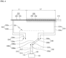
- FIG. 3 is a circuit diagram illustrating a state where a first electrode of FIG. 1 has been connected with the radio frequency generator
- FIG. 4 is a circuit diagram illustrating a state where a second electrode of FIG. 1 has been connected with the radio frequency generator
- FIG. 5 is a circuit diagram illustrating a state where the first electrode and the second electrode of FIG. 1 have been connected with the radio frequency generator
- FIG. 6 is a circuit diagram illustrating a state where the first electrode and the second electrode of FIG. 1 have been disconnected with the radio frequency generator.
- a high-frequency thermal therapy device may include a radio frequency generator 100 for generating a radio frequency current, an electrode 200 for cauterizing a target lesion with the radio frequency current generated from the radio frequency generator 100, and an electric circuit extending from the radio frequency generator 100 to the electrode 200.
- the high-frequency thermal therapy device may further include a cooling device 500 for cooling the electrode.
- the radio frequency generator 100 may be configured such that a radio frequency AC is supplied to the electrode 200 through an active terminal 110 and a passive terminal 120.
- the electrode 200 may be configured as a so-called oblique type bipolar electrode in which a heat generation range is configured to have a cylindrical shape, and may be configured such that heat may be generated from two portions thereof independently.
- the electrode 200 may include a body 210 configured to extend in one direction, a first electrode 220 disposed at one end portion of the body 210, and a second electrode 230 disposed at the other end portion of the body 210.
- the body 210 may be configured to have a needle shape in order to be easily inserted into a target lesion tissue.
- the first electrode 220 may include a first active electrode 222 that is wound in a spiral shape along the outer circumferential surface of the body 210 at one end portion of the body 210 and a first passive electrode 224 that is wound in a spiral shape along the outer circumferential surface of the body 210 at one end portion of the body 210 and wound in parallel with the first active electrode 222.
- the first active electrode 222 and the first passive electrode 224 may be configured by winding in two or more times in parallel at the same lead angle with each other. That is, the first passive electrode 224 is wound in a spiral shape between the first active electrode 222 wound in a spiral shape so that the first active electrode 222 and the first passive electrode 224 are alternately wound, and the alternating interval between the first active electrode 222 and the first passive electrode 224 may be constantly formed (i.e., the pitch P1 between the first active electrode 222 and the first passive electrode 224 may be constantly formed).
- the first active electrode 222 and the first passive electrode 224 may be configured such that the first active electrode 222 is connected to the active terminal 110 of the radio frequency generator 100, and the first passive electrode 224 is connected to the passive terminal 120 of the radio frequency generator 100 through the electric circuit.
- the target lesion may be cauterized by the radio frequency radiation generated between the first active electrode 222 and the first passive electrode 224.
- the first electrode 220 may provide heat generated around the intermediate point of the pitch P1 between the first active electrode 222 and the first passive electrode 224 at the time of radiating the radio frequency energy between the first active electrode 222 and the first passive electrode 224.
- the heat generation range may be formed to have a tubular shape surrounding the body 210, and since the pitch P1 between the first active electrode 222 and the first passive electrode 224 is constant, the heat generation range may be formed to have a cylindrical shape having a rectangular vertical section.
- the second electrode 230 may include a second active electrode 232 that is wound in a spiral shape along the outer circumferential surface of the body 210 at the other end portion of the body 210 and a second passive electrode 234 that is wound in a spiral shape along the outer circumferential surface of the body 210 at the other end portion of the body 210 and wound in parallel with the second active electrode 232.
- the second active electrode 232 and the second passive electrode 234 may be configured by winding in two or more times in parallel at the same lead angle with each other. That is, the second passive electrode 234 is wound in a spiral shape between the second active electrode 232 wound in a spiral shape so that the second active electrode 232 and the second passive electrode 234 are alternately wound, and the alternating interval between the second active electrode 232 and the second passive electrode 234 may be constantly formed (i.e., the pitch P2 between the second active electrode 232 and the second passive electrode 234 may be constantly formed).
- the lead angles and the pitches of the first electrode 220 and the second electrode 230 may be preferably configured at the same level entirely so that the quality of cauterization by the first electrode 220 and the quality of cauterization by the second electrode 230 become the same level as each other.
- the lead angle of the first active electrode 222, the lead angle of the first passive electrode 224, the lead angle of the second active electrode 232, and the lead angle of the second passive electrode 234 are configured to be the same as each other, and the pitch P1 between the first active electrode 222 and the first passive electrode 224, the pitch P2 between the second active electrode 232 and the second passive electrode 234, and the pitch P3 between the first electrode 220 and the second electrode 230 are configured to be the same as each other.
- the second active electrode 232 and the second passive electrode 234 may have the second active electrode 232 connected to the active terminal 110 of the radio frequency generator 100, and have the second passive electrode 234 connected to the passive terminal 120 of the radio frequency generator 100 through the electric circuit.
- the target lesion may be cauterized by the radio frequency radiation generated between the second active electrode 232 and the second passive electrode 234.
- the second electrode 230 may provide heat generated around the intermediate point of the pitch P2 between the second active electrode 232 and the second passive electrode 234 at the time of radiating the radio frequency energy between the second active electrode 232 and the second passive electrode 234.
- the heat generation range may be configured to have a tubular shape surrounding the body 210, and since the pitch P2 between the second active electrode 232 and the second passive electrode 234 are constant, the heat generation range may have a cylindrical shape having a rectangular vertical section.
- the second active electrode 232 and the second passive electrode 234 may be configured to be spaced apart from the first active electrode 222 and the first passive electrode 224 in the extending direction of the body 210 not to be contacted with the first active electrode 222 and the first passive electrode 224. That is, the first electrode 220 and the second electrode 230 may be configured such that the current received into the first active electrode 222 and the first passive electrode 224 does not flow into the second active electrode 232 and the second passive electrode 234, and the vice versa.
- the length L1 of the first electrode 220 may be configured differently from the length L2 of the second electrode 230 so that the cauterization length (i.e., the length in the extending direction of the body 210) by the first electrode 220 is different from the cauterization length (i.e., the length in the extending direction of the body 210) by the second electrode 230.
- the length L1 of the first electrode 220 may be configured at a level of about 3cm
- the length L2 of the second electrode 230 may be configured at a level of about 4cm.
- the electric circuit may include a lead-in wire 310 extending from the radio frequency generator 100, a lead-out wire 320 extending from the electrode 200, and a switch 330 for connecting and disconnecting the lead-in wire 310 and the lead-out wire 320.
- the switch 330 may be disposed at a handle 400 provided at one side of the electrode 200 (more accurately, the body 210), the lead-in wire 310 may be extended into the handle 400 from the radio frequency generator 100 to be connected with the switch 330, and the lead-out wire 320 may be extended from the switch 330 to be connected to the first electrode 220 and the second electrode 230 through the handle 400 and the body 210.
- the lead-in wire 310 may include an active lead-in wire 312 extending from the active terminal 110 of the radio frequency generator 100 and a passive lead-in wire 314 extending from the passive terminal 120 of the radio frequency generator 100.
- the lead-out wire 320 may include a first active lead-out wire 322a extending from the first active electrode 222; a first passive lead-out wire 322b extending from the first passive electrode 224, and constituting a pair of first lead-out wires 322 with the first active lead-out wire 322a; a second active lead-out wire 324a extending from the second active electrode 232; and a second passive lead-out wire 324b extending from the second passive electrode 234, and constituting a pair of second lead-out wires 324 with the second active lead-out wire 324a.
- the switch 330 may include a first terminal 332a connected with the active lead-in wire 312; a second terminal 332b connected with the passive lead-in wire 314, and constituting a pair of input terminals 332 with the first terminal 332a; a third terminal 334a connected with the first active lead-out wire 322a; a fourth terminal 334b connected with the first passive lead-out wire 322b, and constituting a pair of first output terminals 334 with the third terminal 334a; a fifth terminal 336b connected with the second active lead-out wire 324a; a sixth terminal 336a connected with the second passive lead-out wire 324b, and constituting a pair of second output terminals 336 with the fifth terminal 336b; and a bridge 338 for connecting and blocking the pair of input terminals 332 to the pair of first output terminals 334 and the pair of second output terminals 336.
- the bridge 338 may include a first bridge 338a for connecting the input terminal 332 with the first output terminal 334, a second bridge 338b for connecting the input terminal 332 with the second output terminal 336, and a third bridge 338c for connecting the input terminal 332 with the first output terminal 334 and the second output terminal 336.
- the first bridge 338a may include a first active bridge 338aa for connecting the first terminal 332a with the third terminal 334a and a first passive bridge 338ab for connecting the second terminal 332b with the fourth terminal 334b.
- the first active bridge 338aa and the first passive bridge 338ab may be configured to be interlocked with each other.
- the first active bridge 338aa and the first passive bridge 338ab may be configured such that when the first active bridge 338aa is activated (i.e., the first terminal 332a and the third terminal 334a are connected), the first passive bridge 338ab is also activated (i.e., the second terminal 332b and the fourth terminal 334b are connected), and when the first active bridge 338aa is inactivated (i.e., the first terminal 332a and the third terminal 334a are disconnected), the first passive bridge 338ab is also inactivated (i.e., the second terminal 332b and the fourth terminal 334b are disconnected).
- the second bridge 338b may include a second active bridge 338ba for connecting the first terminal 332a with the fifth terminal 336b and a second passive bridge 338bb for connecting the second terminal 332b with the sixth terminal 336a.
- the second active bridge 338ba and the second passive bridge 338bb may be configured to be interlocked with each other.
- the second active bridge 338ba and the second passive bridge 338bb may be configured such that when the second active bridge 338ba is activated (i.e., the first terminal 332a and the fifth terminal 336b are connected), the second passive bridge 338bb is also activated (i.e., the second terminal 332b and the sixth terminal 336a are connected), and when the second active bridge 338ba is inactivated (i.e., the first terminal 332a and the fifth terminal 336b are disconnected), the second passive bridge 338bb is also inactivated (i.e., the second terminal 332b and the sixth terminal 336a are disconnected).
- the third bridge 338c may include a third active bridge 338ca for connecting the first terminal 332a with the third terminal 334a and the fifth terminal 336b and a third passive bridge 338cb for connecting the second terminal 332b with the fourth terminal 334b and the sixth terminal 336a.
- the third active bridge 338ca may be branched to simultaneously connect the first terminal 332a with the third terminal 334a and the fifth terminal 336b
- the third passive bridge 338cb may be branched to simultaneously connect the second terminal 332b with the fourth terminal 334b and the sixth terminal 336a.
- the third active bridge 338ca and the third passive bridge 338cb may be configured to be interlocked with each other.
- the third active bridge 338ca and the third passive bridge 338cb may be configured such that when the third active bridge 338ca is activated (i.e., the first terminal 332a is connected with the third terminal 334a and the fifth terminal 336b), the third passive bridge 338cb is also activated (i.e., the second terminal 332b is connected with the fourth terminal 334b and the sixth terminal 336a), and when the third active bridge 338ca is inactivated (i.e., the first terminal 332a is disconnected with the third terminal 334a and the fifth terminal 336b), the third passive bridge 338cb is also inactivated (i.e., the second terminal 332b is disconnected with the fourth terminal 334b and the sixth terminal 336a).
- any one of the first bridge 338a, the second bridge 338b, and the third bridge 338c may be activated to supply the current generated from the radio frequency generator 100 to at least one of the first electrode 220 and the second electrode 230, or all of the first bridge 338a, the second bridge 338b, and the third bridge 338c may be inactivated to electrically disconnect the first electrode 220 and the second electrode 230 by the radio frequency generator 100.
- the electrode 200 may be inserted into the body of a patient in a state where all of the first bridge 338a, the second bridge 338b, and the third bridge 338c of the switch 330 are inactivated (an OFF state) so that the first electrode 220 or the second electrode 230 of the electrode 200 is disposed at the target lesion, and one of the first bridge 338a, the second bridge 338b, and the third bridge 338c of the switch 330 may be activated to cauterize the target lesion, and the cauterization length thereof may be changed.
- the first electrode 220 may be disposed at the target lesion, and as illustrated in FIG. 3 , when the first bridge 338a is activated, the target lesion may be cauterized at the length of approximately the same level as the length L1 of the first electrode 220 while the radio frequency radiation is generated between the first active electrode 222 to which a current is applied from the active terminal 110 of the radio frequency generator 100 through the active lead-in wire 312, the first terminal 332a, the first active bridge 338aa, the third terminal 334a, and the first active lead-out wire 322a, and the first passive electrode 224 to which a current is applied from the passive terminal 120 of the radio frequency generator 100 through the passive lead-in wire 314, the second terminal 332b, the first passive bridge 338ab, the fourth terminal 334b, and the first passive lead-out wire 322b.
- the cauterization cannot occur in the second electrode
- the second electrode 230 may be disposed at the target lesion, and as illustrated in FIG. 4 , when the second bridge 338b is activated, the target lesion may be cauterized at the length of approximately the same level as the length L2 of the second electrode 230 while the radio frequency radiation is generated between the second active electrode 232 to which a current is applied from the active terminal 110 of the radio frequency generator 100 through the active lead-in wire 312, the first terminal 332a, the second active bridge 338ba, the fifth terminal 336b, and the second active lead-out wire 324a, and the second passive electrode 234 to which a current is applied from the passive terminal 120 of the radio frequency generator 100 through the passive lead-in wire 314, the second terminal 332b, the second passive bridge 338bb, the sixth terminal 336a, and the second passive lead-out wire 324b.
- the cauterization cannot occur in the first electrode 220
- the first electrode 220 and the second electrode 230 may be disposed at the target lesion, and as illustrated in FIG. 5 , when the third bridge 338c is activated, heat is generated from both the first electrode 220 and the second electrode 230 so that the target lesion may be cauterized at the length of approximately the same level as the sum of the length L1 of the first electrode 220 and the length L2 of the second electrode 230.
- a current applied to the active lean-in wire 312 and the first terminal 332a from the active terminal 110 of the radio frequency generator 100 may be branched to the third terminal 334a and the fifth terminal 336b by the third active bridge 338ca, a current branched to the third terminal 334a may be applied to the first active electrode 222 through the first active lead-out wire 322a, and a current branched to the fifth terminal 336b may be applied to the second active electrode 232 through the second active lead-out wire 324a.
- a current applied to the passive lead-in wire 314 and the second terminal 332b from the passive terminal 120 of the radio frequency generator 100 may be branched to the fourth terminal 334b and the sixth terminal 336a by the third passive bridge 338cb, a current branched to the fourth terminal 334b may be applied to the first passive electrode 224 through the first passive lead-out wire 322b, and a current branched to the sixth terminal 336a may be applied to the second passive electrode 234 through the second passive lead-out wire 324b.
- one side of the target lesion may be cauterized at the length of the same level as the length L1 of the first electrode 220 while the radio frequency radiation is generated between the first active electrode 222 and the first passive electrode 224.
- the other side of the target lesion may be cauterized at the length of the same level as the length L2 of the second electrode 230 while the radio frequency radiation is generated between the second active electrode 232 and the second passive electrode 234. Therefore, the entire cauterization length of the target lesion may be the same level as the sum of the length L1 of the first electrode 220 and the length L2 of the second electrode 230.
- the switch 330 may be inactivated (i.e., all of the first bridge 338a, the second bridge 338b, and the third bridge 338c are inactivated), and then the electrode 200 may be drawn out of the patient's body, thereby completing the treatment.
- the high-frequency thermal therapy device of the present embodiment provides the first electrode 220 and the second electrode 230 capable of cauterizing the target lesion, respectively, on the electrode 200, and according to an operation of the switch 330, a power may be applied to the first electrode 220, a power may be applied to the second electrode 230, or a power may be applied to both the first electrode 220 and the second electrode 230, thereby adjusting the cauterization length of the electrode 200.
- the lead angle of the first electrode 220 may be configured to be the same level as the lead angle of the second electrode 230
- the pitch P1 of the first electrode 220 may be configured to be the same level as the pitch P2 of the second electrode 230 so that the cauterization radius by the first electrode 220 and the cauterization radius by the second electrode 230 become the same level.
- the lead angle of the first electrode 220 may be configured to be a level differently from the lead angle of the second electrode 230
- the pitch P1 of the first electrode 220 may also be configured to be a level differently from the pitch P2 of the second electrode 230 so that the cauterization radius by the first electrode 220 and the cauterization radius by the second electrode 230 become a level differently from each other.
- the distance between the first electrode 220 and the second electrode 230 may be configured at the same level as the pitch P1 of the first electrode 220 and the pitch P2 of the second electrode 230 so that the cauterization area by the first electrode 220 and the cauterization area of the second electrode 230 may be connected to each other, and the first electrode 220 and the second electrode 230 may be configured such that the opposite polarities are opposite to each other (e.g., the second passive electrode 234 is configured opposite to the first active electrode 222, or the second active electrode 232 is configured opposite to the first passive electrode 224 at the area where the first electrode 220 and the second electrode 230 are adjacent to each other).
- the distance between the first electrode 220 and the second electrode 230 may be configured longer than the pitch P1 of the first electrode 220 and the pitch P2 of the second electrode 230, and the first electrode 220 and the second electrode 230 may also be configured such that the same polarities are opposite to each other (e.g., the second active electrode 232 is configured opposite to the first active electrode 222, or the second passive electrode 234 is configured opposite to the first passive electrode 224 at the area where the first electrode 220 and the second electrode 230 are adjacent to each other).
- the switch 330 provides all of the first bridge 338a, the second bridge 338b, and the third bridge 338c, and any one of the first bridge 338a, the second bridge 338b, and the third bridge 338c may be activated, or may be all inactivated according to a button operation of the switch 330.
- the present embodiment is not limited thereto, and various embodiments for the switch 330 may be present within the range in which when the cauterization is performed, a current is applied to at least one of the first electrode 220 and the second electrode 230, and when the cauterization is not performed, a current is blocked to both the first electrode 220 and the second electrode 230.
- the electrode 200 is configured as an oblique type bipolar electrode, but although not illustrated separately, it may be configured as an annular bipolar electrode. That is, the electrode may include a plurality of electrode bodies, each electrode may include an active electrode body and a passive electrode body parallel to each other, and the active electrode body and the passive electrode body may be configured to have an annular shape, respectively. Then, the plurality of electrode bodies may be applied with a power through an electric circuit and a switch, and the power may be applied to at least one of the plurality of electrode bodies according to the operation of the switch, thereby adjusting the cauterization length.
- the present disclosure provides the high-frequency thermal therapy device capable of adjusting the cauterization length of the electrode.
Landscapes
- Health & Medical Sciences (AREA)
- Surgery (AREA)
- Life Sciences & Earth Sciences (AREA)
- Engineering & Computer Science (AREA)
- Molecular Biology (AREA)
- General Health & Medical Sciences (AREA)
- Otolaryngology (AREA)
- Veterinary Medicine (AREA)
- Public Health (AREA)
- Biomedical Technology (AREA)
- Heart & Thoracic Surgery (AREA)
- Medical Informatics (AREA)
- Nuclear Medicine, Radiotherapy & Molecular Imaging (AREA)
- Animal Behavior & Ethology (AREA)
- Physics & Mathematics (AREA)
- Plasma & Fusion (AREA)
- Cardiology (AREA)
- Surgical Instruments (AREA)
- Electrotherapy Devices (AREA)
Claims (4)
- Appareil de thermothérapie à hautes fréquences, comprenant:une poignée (400);un corps allongé (210) s'étendant à partir de la poignée (400);une première électrode (220) disposée au niveau d'une partie du corps (210) pour cautériser une lésion cible et comportant une première électrode active (222) et une première électrode passive (224) enroulées en forme de spirale de manière parallèle l'une à l'autre le long d'une surface circonférentielle extérieure du corps (210);une deuxième électrode (230) disposée au niveau d'une autre partie du corps (210) pour cautériser la lésion cible et comportant une deuxième électrode active (232) et une deuxième électrode passive (234) enroulées en forme de spirale de manière parallèle l'une à l'autre le long de la surface circonférentielle extérieure du corps (210);un générateur de radiofréquence (100) destiné à générer un courant de radiofréquence;un circuit électrique destiné à connecter le générateur de radiofréquence (100) aux première (220) et deuxième (230) électrodes; etun commutateur (330) comprenant un premier pont (338a), un deuxième pont (338b) et un troisième pont (338c) disposés sur la poignée (400) pour ouvrir ou fermer le circuit électrique,dans lequel une longueur de la première électrode (220) est différente d'une longueur de la deuxième électrode (230) dans la direction d'extension du corps (210),dans lequel le commutateur (330) comporte:une paire de bornes d'entrée (332) connectées au générateur de radiofréquence (100);une paire de premières bornes de sortie (334) connectées respectivement à la première électrode active (222) et à la première électrode passive (224);une paire de deuxièmes bornes de sortie (336) connectées respectivement à 1a deuxième électrode active (232) et à la deuxième électrode passive (234);les ponts (338a, 338b, 338c) sont configurés pour connecter sélectivement la paire de bornes d'entrée (332) à la paire de premières bornes de sortie (334), à la paire de deuxièmes bornes de sortie (336), ou aux deux, à l'aide respectivement du premier pont (338a), du deuxième pont (338b) et du troisième pont (338c), de manière à modifier une longueur de cautérisation de la lésion cible;dans lequel chaque pont (338a, 338b, 338c) comporte un pont actif et un pont passif qui sont configurés pour être inter-verrouillés l'un avec l'autre de sorte que, lorsque leur pont actif est activé pour connecter l'une de la paire de bornes d'entrée (332) à l'une de la paire de premières bornes de sortie (334) et/ou à l'une de la paire de deuxièmes bornes de sortie (336), le pont passif est également activé pour connecter l'autre de la paire de bornes d'entrée (332) à l'autre de la paire de premières bornes de sortie (334) et/ou à l'autre de la paire de deuxièmes bornes de sortie (336) et, lorsque le pont actif est désactivé pour déconnecter l'une de la paire de bornes d'entrée (332) de l'une de la paire de premières bornes de sortie (334) et/ou de l'une de la paire de deuxièmes bornes de sortie (336), le pont passif est également désactivé pour déconnecter l'autre de la paire de bornes d'entrée (332) de l'autre de la paire de premières bornes de sortie (334) et/ou de l'autre de la paire de deuxièmes bornes de sortie (336).
- Appareil de thermothérapie à hautes fréquences selon la revendication 1,dans lequel, selon le fonctionnement du commutateur (330),la première électrode active (222) et la première électrode passive (224) sont connectées électriquement au générateur de radiofréquence (100);la deuxième électrode active (232) et la deuxième électrode passive (234) sont connectées électriquement au générateur de radiofréquence (100); oula première électrode active (222), la première électrode passive (224), la deuxième électrode active (232) et la deuxième électrode passive (234) sont connectées électriquement au générateur de radiofréquence (100).
- Dispositif de thermothérapie à hautes fréquences selon la revendication 2,
dans lequel le commutateur (330) comprend:une première borne (332a) s'étendant à partir d'une borne active (110) du générateur de radiofréquence (100);une deuxième borne (332b) s'étendant à partir d'une borne passive (120) du générateur de radiofréquence (100), et constituant la paire de bornes d'entrée (332) avec la première borne (332a);une troisième borne (334a) s'étendant à partir de la première électrode active (222);une quatrième borne (334b) s'étendant à partir de la première électrode passive (224) et constituant la paire de premières bornes de sortie (334) avec la troisième borne (334a);une cinquième borne (336b) s'étendant à partir de la deuxième électrode active (232);une sixième borne (336a) s'étendant à partir de la deuxième électrode passive (234) et constituant la paire de deuxièmes bornes de sortie (336) avec la cinquième borne (336b); etdans lequel le pont (338) est configuré pour connecter la paire de bornes d'entrée (332) à ou pour bloquer la paire de bornes d'entrée (332) de la paire de premières bornes de sortie (334) et de la paire de deuxièmes bornes de sortie (336). - Dispositif de thermothérapie à hautes fréquences selon la revendication 4,
dans lequel le premier pont (338a) comprend:un premier pont actif (338aa) destiné à connecter la première borne (332a) au troisième borne (334a); etun premier pont passif (338ab) destiné à connecter la deuxième borne (332b) au quatrième borne (334b),dans lequel le deuxième pont (338b) comprend:un deuxième pont actif (338ba) destiné à connecter la première borne (332a) à la cinquième borne (336b); etun deuxième pont passif (338bb) destiné à connecter la deuxième borne (332b) à la sixième borne (336a), etdans lequel le troisième pont (338c) comprend:un troisième pont actif (338ca) destiné à connecter la première borne (332a) à la troisième borne (334a) et à la cinquième borne (336b); etun troisième pont passif (338cb) destiné à connecter la deuxième borne (332b) à la quatrième borne (334b) et à la sixième borne (336a).
Applications Claiming Priority (2)
| Application Number | Priority Date | Filing Date | Title |
|---|---|---|---|
| KR1020160146450A KR101963621B1 (ko) | 2016-11-04 | 2016-11-04 | 고주파 열 치료 장치 |
| PCT/KR2017/011305 WO2018084445A1 (fr) | 2016-11-04 | 2017-10-13 | Dispositif de thérapie thermique haute fréquence |
Publications (3)
| Publication Number | Publication Date |
|---|---|
| EP3536274A1 EP3536274A1 (fr) | 2019-09-11 |
| EP3536274A4 EP3536274A4 (fr) | 2020-07-22 |
| EP3536274B1 true EP3536274B1 (fr) | 2024-07-31 |
Family
ID=62075559
Family Applications (1)
| Application Number | Title | Priority Date | Filing Date |
|---|---|---|---|
| EP17867185.5A Active EP3536274B1 (fr) | 2016-11-04 | 2017-10-13 | Dispositif de thérapie thermique haute fréquence |
Country Status (7)
| Country | Link |
|---|---|
| US (1) | US20200085490A1 (fr) |
| EP (1) | EP3536274B1 (fr) |
| JP (1) | JP6850042B2 (fr) |
| KR (1) | KR101963621B1 (fr) |
| CN (1) | CN109890307B (fr) |
| ES (1) | ES2990146T3 (fr) |
| WO (1) | WO2018084445A1 (fr) |
Families Citing this family (2)
| Publication number | Priority date | Publication date | Assignee | Title |
|---|---|---|---|---|
| CN111067617A (zh) * | 2019-12-27 | 2020-04-28 | 苏州恒瑞宏远医疗科技有限公司 | 射频闭合导管及其制作方法 |
| KR102655015B1 (ko) | 2023-06-07 | 2024-04-05 | (주)알에프메디컬 | 갑상선 고주파 소작용 전극 |
Citations (3)
| Publication number | Priority date | Publication date | Assignee | Title |
|---|---|---|---|---|
| US5562720A (en) * | 1992-05-01 | 1996-10-08 | Vesta Medical, Inc. | Bipolar/monopolar endometrial ablation device and method |
| US6356790B1 (en) * | 1996-03-11 | 2002-03-12 | Medtronic, Inc. | Apparatus for R-F ablation |
| US20160022353A1 (en) * | 2014-07-28 | 2016-01-28 | Boston Scientific Scimed, Inc. | Multiple lead electrode probe for controlled tissue ablation |
Family Cites Families (16)
| Publication number | Priority date | Publication date | Assignee | Title |
|---|---|---|---|---|
| US6129724A (en) * | 1993-10-14 | 2000-10-10 | Ep Technologies, Inc. | Systems and methods for forming elongated lesion patterns in body tissue using straight or curvilinear electrode elements |
| US5545193A (en) * | 1993-10-15 | 1996-08-13 | Ep Technologies, Inc. | Helically wound radio-frequency emitting electrodes for creating lesions in body tissue |
| US6117131A (en) * | 1995-06-09 | 2000-09-12 | Engineering & Research Associates, Inc. | Multi-electrode probe for thermal ablation |
| US5697925A (en) * | 1995-06-09 | 1997-12-16 | Engineering & Research Associates, Inc. | Apparatus and method for thermal ablation |
| US6251107B1 (en) * | 1998-06-25 | 2001-06-26 | Cardima, Inc. | Ep catheter |
| US6743226B2 (en) * | 2001-02-09 | 2004-06-01 | Cosman Company, Inc. | Adjustable trans-urethral radio-frequency ablation |
| WO2009089415A1 (fr) * | 2008-01-09 | 2009-07-16 | Mayo Foundation For Medical Education And Research | Système de cartographie et de cathéter d'ablation |
| US8241222B2 (en) * | 2008-07-31 | 2012-08-14 | Medtronic, Inc. | Monitoring hemodynamic status based on intracardiac or vascular impedance |
| KR101125857B1 (ko) * | 2009-08-04 | 2012-04-12 | 유한철 | 고주파 치료 장치 및 그 제어방법 |
| GB2477350B (en) * | 2010-02-01 | 2015-09-09 | Gyrus Medical Ltd | Electrosurgical system |
| KR20120126706A (ko) * | 2011-05-12 | 2012-11-21 | (주) 태웅메디칼 | 고주파 열치료용 비대칭 바이폴라 전극침 |
| ES2703556T3 (es) * | 2011-10-15 | 2019-03-11 | Diros Tech Inc | Aparato para controlar con precisión el tamaño y la forma de ablaciones por radiofrecuencia |
| KR101415900B1 (ko) * | 2012-05-18 | 2014-07-08 | 신경민 | 고주파 열치료용 중첩형 바이폴라 전극 |
| KR101415902B1 (ko) * | 2012-05-18 | 2014-07-08 | 신경민 | 소작 겸용 스텐트 시술장치 |
| US9827036B2 (en) * | 2012-11-13 | 2017-11-28 | Pulnovo Medical (Wuxi) Co., Ltd. | Multi-pole synchronous pulmonary artery radiofrequency ablation catheter |
| KR101645273B1 (ko) * | 2014-06-09 | 2016-08-05 | 주식회사 스타메드 | 고주파 열 치료용 바이폴라 전극 |
-
2016
- 2016-11-04 KR KR1020160146450A patent/KR101963621B1/ko active Active
-
2017
- 2017-10-13 WO PCT/KR2017/011305 patent/WO2018084445A1/fr not_active Ceased
- 2017-10-13 EP EP17867185.5A patent/EP3536274B1/fr active Active
- 2017-10-13 ES ES17867185T patent/ES2990146T3/es active Active
- 2017-10-13 CN CN201780065828.7A patent/CN109890307B/zh active Active
- 2017-10-13 JP JP2019522503A patent/JP6850042B2/ja active Active
- 2017-10-13 US US16/347,158 patent/US20200085490A1/en not_active Abandoned
Patent Citations (3)
| Publication number | Priority date | Publication date | Assignee | Title |
|---|---|---|---|---|
| US5562720A (en) * | 1992-05-01 | 1996-10-08 | Vesta Medical, Inc. | Bipolar/monopolar endometrial ablation device and method |
| US6356790B1 (en) * | 1996-03-11 | 2002-03-12 | Medtronic, Inc. | Apparatus for R-F ablation |
| US20160022353A1 (en) * | 2014-07-28 | 2016-01-28 | Boston Scientific Scimed, Inc. | Multiple lead electrode probe for controlled tissue ablation |
Also Published As
| Publication number | Publication date |
|---|---|
| EP3536274A4 (fr) | 2020-07-22 |
| WO2018084445A1 (fr) | 2018-05-11 |
| CN109890307A (zh) | 2019-06-14 |
| JP2019533522A (ja) | 2019-11-21 |
| KR101963621B1 (ko) | 2019-04-01 |
| EP3536274A1 (fr) | 2019-09-11 |
| US20200085490A1 (en) | 2020-03-19 |
| KR20180050448A (ko) | 2018-05-15 |
| CN109890307B (zh) | 2021-11-30 |
| ES2990146T3 (es) | 2024-11-29 |
| JP6850042B2 (ja) | 2021-03-31 |
Similar Documents
| Publication | Publication Date | Title |
|---|---|---|
| US20240189016A1 (en) | Method and Apparatus for Precisely Controlling the Size and Shape of Radiofrequency Ablations | |
| JP7075922B2 (ja) | 双極型組織切除装置及びその使用方法 | |
| US20060167448A1 (en) | Electrophysiology catheter with ablation electrode | |
| EP3634289B1 (fr) | Instrument électrochirurgical pour effectuer une ablation ou une électroporation de tissu biologique | |
| US9770293B2 (en) | Systems and methods for treating tissue of a passageway within a body | |
| JP2015521873A (ja) | 電気外科用切除器具 | |
| KR101415900B1 (ko) | 고주파 열치료용 중첩형 바이폴라 전극 | |
| JP2010505552A (ja) | 電気外科的装置 | |
| JP2021531837A (ja) | 電気手術器具 | |
| EP3326561B1 (fr) | Bipolar electrode for radio frequency ablation | |
| CN108013931A (zh) | 一种低温等离子体手术电极 | |
| EP3536274B1 (fr) | Dispositif de thérapie thermique haute fréquence | |
| KR101489197B1 (ko) | 고주파 치료용 카테터 전극 | |
| HK1244650A1 (en) | Electrosurgical resection instrument | |
| HK1208329B (en) | Electrosurgical resection instrument |
Legal Events
| Date | Code | Title | Description |
|---|---|---|---|
| STAA | Information on the status of an ep patent application or granted ep patent |
Free format text: STATUS: THE INTERNATIONAL PUBLICATION HAS BEEN MADE |
|
| PUAI | Public reference made under article 153(3) epc to a published international application that has entered the european phase |
Free format text: ORIGINAL CODE: 0009012 |
|
| STAA | Information on the status of an ep patent application or granted ep patent |
Free format text: STATUS: REQUEST FOR EXAMINATION WAS MADE |
|
| 17P | Request for examination filed |
Effective date: 20190502 |
|
| AK | Designated contracting states |
Kind code of ref document: A1 Designated state(s): AL AT BE BG CH CY CZ DE DK EE ES FI FR GB GR HR HU IE IS IT LI LT LU LV MC MK MT NL NO PL PT RO RS SE SI SK SM TR |
|
| AX | Request for extension of the european patent |
Extension state: BA ME |
|
| RIN1 | Information on inventor provided before grant (corrected) |
Inventor name: SHIN, KYUNG HOON Inventor name: LIM, HYUK |
|
| DAV | Request for validation of the european patent (deleted) | ||
| DAX | Request for extension of the european patent (deleted) | ||
| A4 | Supplementary search report drawn up and despatched |
Effective date: 20200624 |
|
| RIC1 | Information provided on ipc code assigned before grant |
Ipc: A61B 18/12 20060101ALI20200618BHEP Ipc: A61B 18/00 20060101ALI20200618BHEP Ipc: A61B 18/14 20060101AFI20200618BHEP |
|
| STAA | Information on the status of an ep patent application or granted ep patent |
Free format text: STATUS: EXAMINATION IS IN PROGRESS |
|
| 17Q | First examination report despatched |
Effective date: 20230817 |
|
| GRAP | Despatch of communication of intention to grant a patent |
Free format text: ORIGINAL CODE: EPIDOSNIGR1 |
|
| STAA | Information on the status of an ep patent application or granted ep patent |
Free format text: STATUS: GRANT OF PATENT IS INTENDED |
|
| INTG | Intention to grant announced |
Effective date: 20240223 |
|
| GRAS | Grant fee paid |
Free format text: ORIGINAL CODE: EPIDOSNIGR3 |
|
| GRAA | (expected) grant |
Free format text: ORIGINAL CODE: 0009210 |
|
| STAA | Information on the status of an ep patent application or granted ep patent |
Free format text: STATUS: THE PATENT HAS BEEN GRANTED |
|
| AK | Designated contracting states |
Kind code of ref document: B1 Designated state(s): AL AT BE BG CH CY CZ DE DK EE ES FI FR GB GR HR HU IE IS IT LI LT LU LV MC MK MT NL NO PL PT RO RS SE SI SK SM TR |
|
| REG | Reference to a national code |
Ref country code: CH Ref legal event code: EP Ref country code: GB Ref legal event code: FG4D |
|
| REG | Reference to a national code |
Ref country code: DE Ref legal event code: R096 Ref document number: 602017083762 Country of ref document: DE |
|
| REG | Reference to a national code |
Ref country code: IE Ref legal event code: FG4D |
|
| REG | Reference to a national code |
Ref country code: LT Ref legal event code: MG9D |
|
| REG | Reference to a national code |
Ref country code: ES Ref legal event code: FG2A Ref document number: 2990146 Country of ref document: ES Kind code of ref document: T3 Effective date: 20241129 |
|
| REG | Reference to a national code |
Ref country code: NL Ref legal event code: MP Effective date: 20240731 |
|
| PG25 | Lapsed in a contracting state [announced via postgrant information from national office to epo] |
Ref country code: PT Free format text: LAPSE BECAUSE OF FAILURE TO SUBMIT A TRANSLATION OF THE DESCRIPTION OR TO PAY THE FEE WITHIN THE PRESCRIBED TIME-LIMIT Effective date: 20241202 |
|
| REG | Reference to a national code |
Ref country code: AT Ref legal event code: MK05 Ref document number: 1707755 Country of ref document: AT Kind code of ref document: T Effective date: 20240731 |
|
| PG25 | Lapsed in a contracting state [announced via postgrant information from national office to epo] |
Ref country code: PT Free format text: LAPSE BECAUSE OF FAILURE TO SUBMIT A TRANSLATION OF THE DESCRIPTION OR TO PAY THE FEE WITHIN THE PRESCRIBED TIME-LIMIT Effective date: 20241202 |
|
| PG25 | Lapsed in a contracting state [announced via postgrant information from national office to epo] |
Ref country code: NO Free format text: LAPSE BECAUSE OF FAILURE TO SUBMIT A TRANSLATION OF THE DESCRIPTION OR TO PAY THE FEE WITHIN THE PRESCRIBED TIME-LIMIT Effective date: 20241031 |
|
| PG25 | Lapsed in a contracting state [announced via postgrant information from national office to epo] |
Ref country code: NL Free format text: LAPSE BECAUSE OF FAILURE TO SUBMIT A TRANSLATION OF THE DESCRIPTION OR TO PAY THE FEE WITHIN THE PRESCRIBED TIME-LIMIT Effective date: 20240731 Ref country code: GR Free format text: LAPSE BECAUSE OF FAILURE TO SUBMIT A TRANSLATION OF THE DESCRIPTION OR TO PAY THE FEE WITHIN THE PRESCRIBED TIME-LIMIT Effective date: 20241101 Ref country code: PL Free format text: LAPSE BECAUSE OF FAILURE TO SUBMIT A TRANSLATION OF THE DESCRIPTION OR TO PAY THE FEE WITHIN THE PRESCRIBED TIME-LIMIT Effective date: 20240731 Ref country code: FI Free format text: LAPSE BECAUSE OF FAILURE TO SUBMIT A TRANSLATION OF THE DESCRIPTION OR TO PAY THE FEE WITHIN THE PRESCRIBED TIME-LIMIT Effective date: 20240731 |
|
| PG25 | Lapsed in a contracting state [announced via postgrant information from national office to epo] |
Ref country code: BG Free format text: LAPSE BECAUSE OF FAILURE TO SUBMIT A TRANSLATION OF THE DESCRIPTION OR TO PAY THE FEE WITHIN THE PRESCRIBED TIME-LIMIT Effective date: 20240731 |
|
| PG25 | Lapsed in a contracting state [announced via postgrant information from national office to epo] |
Ref country code: LV Free format text: LAPSE BECAUSE OF FAILURE TO SUBMIT A TRANSLATION OF THE DESCRIPTION OR TO PAY THE FEE WITHIN THE PRESCRIBED TIME-LIMIT Effective date: 20240731 |
|
| PG25 | Lapsed in a contracting state [announced via postgrant information from national office to epo] |
Ref country code: IS Free format text: LAPSE BECAUSE OF FAILURE TO SUBMIT A TRANSLATION OF THE DESCRIPTION OR TO PAY THE FEE WITHIN THE PRESCRIBED TIME-LIMIT Effective date: 20241130 Ref country code: AT Free format text: LAPSE BECAUSE OF FAILURE TO SUBMIT A TRANSLATION OF THE DESCRIPTION OR TO PAY THE FEE WITHIN THE PRESCRIBED TIME-LIMIT Effective date: 20240731 |
|
| PG25 | Lapsed in a contracting state [announced via postgrant information from national office to epo] |
Ref country code: HR Free format text: LAPSE BECAUSE OF FAILURE TO SUBMIT A TRANSLATION OF THE DESCRIPTION OR TO PAY THE FEE WITHIN THE PRESCRIBED TIME-LIMIT Effective date: 20240731 |
|
| PG25 | Lapsed in a contracting state [announced via postgrant information from national office to epo] |
Ref country code: RS Free format text: LAPSE BECAUSE OF FAILURE TO SUBMIT A TRANSLATION OF THE DESCRIPTION OR TO PAY THE FEE WITHIN THE PRESCRIBED TIME-LIMIT Effective date: 20241031 |
|
| PG25 | Lapsed in a contracting state [announced via postgrant information from national office to epo] |
Ref country code: RS Free format text: LAPSE BECAUSE OF FAILURE TO SUBMIT A TRANSLATION OF THE DESCRIPTION OR TO PAY THE FEE WITHIN THE PRESCRIBED TIME-LIMIT Effective date: 20241031 Ref country code: PL Free format text: LAPSE BECAUSE OF FAILURE TO SUBMIT A TRANSLATION OF THE DESCRIPTION OR TO PAY THE FEE WITHIN THE PRESCRIBED TIME-LIMIT Effective date: 20240731 Ref country code: NO Free format text: LAPSE BECAUSE OF FAILURE TO SUBMIT A TRANSLATION OF THE DESCRIPTION OR TO PAY THE FEE WITHIN THE PRESCRIBED TIME-LIMIT Effective date: 20241031 Ref country code: NL Free format text: LAPSE BECAUSE OF FAILURE TO SUBMIT A TRANSLATION OF THE DESCRIPTION OR TO PAY THE FEE WITHIN THE PRESCRIBED TIME-LIMIT Effective date: 20240731 Ref country code: LV Free format text: LAPSE BECAUSE OF FAILURE TO SUBMIT A TRANSLATION OF THE DESCRIPTION OR TO PAY THE FEE WITHIN THE PRESCRIBED TIME-LIMIT Effective date: 20240731 Ref country code: IS Free format text: LAPSE BECAUSE OF FAILURE TO SUBMIT A TRANSLATION OF THE DESCRIPTION OR TO PAY THE FEE WITHIN THE PRESCRIBED TIME-LIMIT Effective date: 20241130 Ref country code: HR Free format text: LAPSE BECAUSE OF FAILURE TO SUBMIT A TRANSLATION OF THE DESCRIPTION OR TO PAY THE FEE WITHIN THE PRESCRIBED TIME-LIMIT Effective date: 20240731 Ref country code: GR Free format text: LAPSE BECAUSE OF FAILURE TO SUBMIT A TRANSLATION OF THE DESCRIPTION OR TO PAY THE FEE WITHIN THE PRESCRIBED TIME-LIMIT Effective date: 20241101 Ref country code: FI Free format text: LAPSE BECAUSE OF FAILURE TO SUBMIT A TRANSLATION OF THE DESCRIPTION OR TO PAY THE FEE WITHIN THE PRESCRIBED TIME-LIMIT Effective date: 20240731 Ref country code: BG Free format text: LAPSE BECAUSE OF FAILURE TO SUBMIT A TRANSLATION OF THE DESCRIPTION OR TO PAY THE FEE WITHIN THE PRESCRIBED TIME-LIMIT Effective date: 20240731 Ref country code: AT Free format text: LAPSE BECAUSE OF FAILURE TO SUBMIT A TRANSLATION OF THE DESCRIPTION OR TO PAY THE FEE WITHIN THE PRESCRIBED TIME-LIMIT Effective date: 20240731 |
|
| PG25 | Lapsed in a contracting state [announced via postgrant information from national office to epo] |
Ref country code: RO Free format text: LAPSE BECAUSE OF FAILURE TO SUBMIT A TRANSLATION OF THE DESCRIPTION OR TO PAY THE FEE WITHIN THE PRESCRIBED TIME-LIMIT Effective date: 20240731 Ref country code: SM Free format text: LAPSE BECAUSE OF FAILURE TO SUBMIT A TRANSLATION OF THE DESCRIPTION OR TO PAY THE FEE WITHIN THE PRESCRIBED TIME-LIMIT Effective date: 20240731 Ref country code: DK Free format text: LAPSE BECAUSE OF FAILURE TO SUBMIT A TRANSLATION OF THE DESCRIPTION OR TO PAY THE FEE WITHIN THE PRESCRIBED TIME-LIMIT Effective date: 20240731 |
|
| PG25 | Lapsed in a contracting state [announced via postgrant information from national office to epo] |
Ref country code: EE Free format text: LAPSE BECAUSE OF FAILURE TO SUBMIT A TRANSLATION OF THE DESCRIPTION OR TO PAY THE FEE WITHIN THE PRESCRIBED TIME-LIMIT Effective date: 20240731 |
|
| PG25 | Lapsed in a contracting state [announced via postgrant information from national office to epo] |
Ref country code: CZ Free format text: LAPSE BECAUSE OF FAILURE TO SUBMIT A TRANSLATION OF THE DESCRIPTION OR TO PAY THE FEE WITHIN THE PRESCRIBED TIME-LIMIT Effective date: 20240731 |
|
| PG25 | Lapsed in a contracting state [announced via postgrant information from national office to epo] |
Ref country code: SK Free format text: LAPSE BECAUSE OF FAILURE TO SUBMIT A TRANSLATION OF THE DESCRIPTION OR TO PAY THE FEE WITHIN THE PRESCRIBED TIME-LIMIT Effective date: 20240731 |
|
| REG | Reference to a national code |
Ref country code: DE Ref legal event code: R097 Ref document number: 602017083762 Country of ref document: DE |
|
| REG | Reference to a national code |
Ref country code: CH Ref legal event code: PL |
|
| PLBE | No opposition filed within time limit |
Free format text: ORIGINAL CODE: 0009261 |
|
| STAA | Information on the status of an ep patent application or granted ep patent |
Free format text: STATUS: NO OPPOSITION FILED WITHIN TIME LIMIT |
|
| PG25 | Lapsed in a contracting state [announced via postgrant information from national office to epo] |
Ref country code: MC Free format text: LAPSE BECAUSE OF FAILURE TO SUBMIT A TRANSLATION OF THE DESCRIPTION OR TO PAY THE FEE WITHIN THE PRESCRIBED TIME-LIMIT Effective date: 20240731 |
|
| 26N | No opposition filed |
Effective date: 20250501 |
|
| PG25 | Lapsed in a contracting state [announced via postgrant information from national office to epo] |
Ref country code: BE Free format text: LAPSE BECAUSE OF NON-PAYMENT OF DUE FEES Effective date: 20241031 Ref country code: LU Free format text: LAPSE BECAUSE OF NON-PAYMENT OF DUE FEES Effective date: 20241013 |
|
| PG25 | Lapsed in a contracting state [announced via postgrant information from national office to epo] |
Ref country code: CH Free format text: LAPSE BECAUSE OF NON-PAYMENT OF DUE FEES Effective date: 20241031 |
|
| REG | Reference to a national code |
Ref country code: BE Ref legal event code: MM Effective date: 20241031 |
|
| PG25 | Lapsed in a contracting state [announced via postgrant information from national office to epo] |
Ref country code: SE Free format text: LAPSE BECAUSE OF FAILURE TO SUBMIT A TRANSLATION OF THE DESCRIPTION OR TO PAY THE FEE WITHIN THE PRESCRIBED TIME-LIMIT Effective date: 20240731 |
|
| PG25 | Lapsed in a contracting state [announced via postgrant information from national office to epo] |
Ref country code: IE Free format text: LAPSE BECAUSE OF NON-PAYMENT OF DUE FEES Effective date: 20241013 |
|
| PGFP | Annual fee paid to national office [announced via postgrant information from national office to epo] |
Ref country code: DE Payment date: 20251002 Year of fee payment: 9 |
|
| PGFP | Annual fee paid to national office [announced via postgrant information from national office to epo] |
Ref country code: GB Payment date: 20251024 Year of fee payment: 9 |
|
| PGFP | Annual fee paid to national office [announced via postgrant information from national office to epo] |
Ref country code: IT Payment date: 20251030 Year of fee payment: 9 |
|
| PGFP | Annual fee paid to national office [announced via postgrant information from national office to epo] |
Ref country code: FR Payment date: 20251024 Year of fee payment: 9 |
|
| PG25 | Lapsed in a contracting state [announced via postgrant information from national office to epo] |
Ref country code: CY Free format text: LAPSE BECAUSE OF FAILURE TO SUBMIT A TRANSLATION OF THE DESCRIPTION OR TO PAY THE FEE WITHIN THE PRESCRIBED TIME-LIMIT; INVALID AB INITIO Effective date: 20171013 |
|
| PGFP | Annual fee paid to national office [announced via postgrant information from national office to epo] |
Ref country code: ES Payment date: 20251103 Year of fee payment: 9 |
|
| PG25 | Lapsed in a contracting state [announced via postgrant information from national office to epo] |
Ref country code: HU Free format text: LAPSE BECAUSE OF FAILURE TO SUBMIT A TRANSLATION OF THE DESCRIPTION OR TO PAY THE FEE WITHIN THE PRESCRIBED TIME-LIMIT; INVALID AB INITIO Effective date: 20171013 |