EP3536603B1 - Bodenplatten und fussbodensysteme für ein fahrzeug und verfahren zur installation - Google Patents
Bodenplatten und fussbodensysteme für ein fahrzeug und verfahren zur installation Download PDFInfo
- Publication number
- EP3536603B1 EP3536603B1 EP19158756.7A EP19158756A EP3536603B1 EP 3536603 B1 EP3536603 B1 EP 3536603B1 EP 19158756 A EP19158756 A EP 19158756A EP 3536603 B1 EP3536603 B1 EP 3536603B1
- Authority
- EP
- European Patent Office
- Prior art keywords
- floor
- panels
- floor panel
- floor panels
- panel
- Prior art date
- Legal status (The legal status is an assumption and is not a legal conclusion. Google has not performed a legal analysis and makes no representation as to the accuracy of the status listed.)
- Active
Links
Images




Classifications
-
- B—PERFORMING OPERATIONS; TRANSPORTING
- B32—LAYERED PRODUCTS
- B32B—LAYERED PRODUCTS, i.e. PRODUCTS BUILT-UP OF STRATA OF FLAT OR NON-FLAT, e.g. CELLULAR OR HONEYCOMB, FORM
- B32B3/00—Layered products comprising a layer with external or internal discontinuities or unevennesses, or a layer of non-planar shape; Layered products comprising a layer having particular features of form
- B32B3/10—Layered products comprising a layer with external or internal discontinuities or unevennesses, or a layer of non-planar shape; Layered products comprising a layer having particular features of form characterised by a discontinuous layer, i.e. formed of separate pieces of material
- B32B3/12—Layered products comprising a layer with external or internal discontinuities or unevennesses, or a layer of non-planar shape; Layered products comprising a layer having particular features of form characterised by a discontinuous layer, i.e. formed of separate pieces of material characterised by a layer of regularly- arranged cells, e.g. a honeycomb structure
-
- B—PERFORMING OPERATIONS; TRANSPORTING
- B64—AIRCRAFT; AVIATION; COSMONAUTICS
- B64C—AEROPLANES; HELICOPTERS
- B64C1/00—Fuselages; Constructional features common to fuselages, wings, stabilising surfaces or the like
- B64C1/18—Floors
-
- B—PERFORMING OPERATIONS; TRANSPORTING
- B32—LAYERED PRODUCTS
- B32B—LAYERED PRODUCTS, i.e. PRODUCTS BUILT-UP OF STRATA OF FLAT OR NON-FLAT, e.g. CELLULAR OR HONEYCOMB, FORM
- B32B3/00—Layered products comprising a layer with external or internal discontinuities or unevennesses, or a layer of non-planar shape; Layered products comprising a layer having particular features of form
- B32B3/02—Layered products comprising a layer with external or internal discontinuities or unevennesses, or a layer of non-planar shape; Layered products comprising a layer having particular features of form characterised by features of form at particular places, e.g. in edge regions
- B32B3/06—Layered products comprising a layer with external or internal discontinuities or unevennesses, or a layer of non-planar shape; Layered products comprising a layer having particular features of form characterised by features of form at particular places, e.g. in edge regions for securing layers together; for attaching the product to another member, e.g. to a support, or to another product, e.g. groove/tongue, interlocking
-
- B—PERFORMING OPERATIONS; TRANSPORTING
- B32—LAYERED PRODUCTS
- B32B—LAYERED PRODUCTS, i.e. PRODUCTS BUILT-UP OF STRATA OF FLAT OR NON-FLAT, e.g. CELLULAR OR HONEYCOMB, FORM
- B32B33/00—Layered products characterised by particular properties or particular surface features, e.g. particular surface coatings; Layered products designed for particular purposes not covered by another single class
-
- B—PERFORMING OPERATIONS; TRANSPORTING
- B61—RAILWAYS
- B61D—BODY DETAILS OR KINDS OF RAILWAY VEHICLES
- B61D17/00—Construction details of vehicle bodies
- B61D17/04—Construction details of vehicle bodies with bodies of metal; with composite, e.g. metal and wood body structures
- B61D17/10—Floors
-
- B—PERFORMING OPERATIONS; TRANSPORTING
- B62—LAND VEHICLES FOR TRAVELLING OTHERWISE THAN ON RAILS
- B62D—MOTOR VEHICLES; TRAILERS
- B62D25/00—Superstructure or monocoque structure sub-units; Parts or details thereof not otherwise provided for
- B62D25/20—Floors or bottom sub-units
-
- B—PERFORMING OPERATIONS; TRANSPORTING
- B63—SHIPS OR OTHER WATERBORNE VESSELS; RELATED EQUIPMENT
- B63B—SHIPS OR OTHER WATERBORNE VESSELS; EQUIPMENT FOR SHIPPING
- B63B3/00—Hulls characterised by their structure or component parts
- B63B3/14—Hull parts
- B63B3/48—Decks
-
- B—PERFORMING OPERATIONS; TRANSPORTING
- B63—SHIPS OR OTHER WATERBORNE VESSELS; RELATED EQUIPMENT
- B63B—SHIPS OR OTHER WATERBORNE VESSELS; EQUIPMENT FOR SHIPPING
- B63B3/00—Hulls characterised by their structure or component parts
- B63B3/14—Hull parts
- B63B3/68—Panellings; Linings, e.g. for insulating purposes
-
- B—PERFORMING OPERATIONS; TRANSPORTING
- B64—AIRCRAFT; AVIATION; COSMONAUTICS
- B64C—AEROPLANES; HELICOPTERS
- B64C1/00—Fuselages; Constructional features common to fuselages, wings, stabilising surfaces or the like
- B64C1/18—Floors
- B64C1/20—Floors specially adapted for freight
-
- B—PERFORMING OPERATIONS; TRANSPORTING
- B64—AIRCRAFT; AVIATION; COSMONAUTICS
- B64F—GROUND OR AIRCRAFT-CARRIER-DECK INSTALLATIONS SPECIALLY ADAPTED FOR USE IN CONNECTION WITH AIRCRAFT; DESIGNING, MANUFACTURING, ASSEMBLING, CLEANING, MAINTAINING OR REPAIRING AIRCRAFT, NOT OTHERWISE PROVIDED FOR; HANDLING, TRANSPORTING, TESTING OR INSPECTING AIRCRAFT COMPONENTS, NOT OTHERWISE PROVIDED FOR
- B64F5/00—Designing, manufacturing, assembling, cleaning, maintaining or repairing aircraft, not otherwise provided for; Handling, transporting, testing or inspecting aircraft components, not otherwise provided for
- B64F5/10—Manufacturing or assembling aircraft, e.g. jigs therefor
-
- E—FIXED CONSTRUCTIONS
- E04—BUILDING
- E04F—FINISHING WORK ON BUILDINGS, e.g. STAIRS, FLOORS
- E04F15/00—Flooring
- E04F15/02—Flooring or floor layers composed of a number of similar elements
-
- B—PERFORMING OPERATIONS; TRANSPORTING
- B32—LAYERED PRODUCTS
- B32B—LAYERED PRODUCTS, i.e. PRODUCTS BUILT-UP OF STRATA OF FLAT OR NON-FLAT, e.g. CELLULAR OR HONEYCOMB, FORM
- B32B2605/00—Vehicles
- B32B2605/18—Aircraft
Definitions
- the present disclosure generally relates to floor panels, and more particularly to, interlocking floor panels that can enable relative motion to occur between adjacent floor panels.
- Cabin floors for commercial and military aircraft can typically include a structural sub-floor with a thin laminate covering and a top floor covering sealed to the thin laminate covering.
- a moisture barrier tape can be provided along seams of the sub-floor as well.
- double back tape is laid down on the entire sub-floor area, to which the rigid laminate sections are laid and sealed. Then, a second layer of double back tape is laid over the laminate sections, followed by panels of the top floor covering.
- At least some known conventional flooring for use in buildings such as hardwood or solid, hard flooring (e.g., tile or laminate) may not be practical for use on an aircraft because the aircraft flooring described above is configured to withstand certain vertical loads (e.g., about three times gravity) that hard flooring used in buildings does not experience.
- a sub-floor on an aircraft or other vehicle is configured to move (i.e., shift with respect to a structural component and/or flex), which can make traditional hardwood or solid flooring impractical.
- hardwood flooring used in buildings can be relatively heavy, causing unnecessary extra weight on the aircraft.
- air pockets in adhesives can expand and/or contract over time making a surface un-level when the aircraft is at cruise altitude (e.g., lower pressure).
- hardwood flooring for use in buildings generally does not absorb noise as well as carpet, and spills can create a slip hazard on hard flooring types for use in buildings.
- Embodiments of the non-planar composite panel comprise: a first sheet including a first outer surface and a first inner surface; a second sheet spaced apart from the first sheet and including a second outer surface and a second inner surface; a stiffening core element disposed between the first and second sheets and defining a plurality of cells; a rigid foam reinforcing material disposed in the cells; and a mirrored third sheet adhered to the first outer surface of the first concave sheet.
- Document WO 2010/078822 in accordance with its abstract, relates to a wooden composite honeycomb floor including a metal honeycomb, a wooden sheet and a bond, wherein at least one surface of the top and bottom surfaces of the metal honeycomb is bonded to the wooden sheet by the bond, and the periphery of the metal honeycomb is filled with fillers or embedded with edge sealing strips.
- the composite honeycomb floor can reduce the consumption of wood and save energy.
- Document US 2011/006562 in accordance with its abstract, relates to a modular floor system comprising at least one floor panel for use in a vehicle.
- the floor panel is comprised of a top surface material and an interlocking subfloor having one or more interlocking pieces.
- the top surface material and the interlocking subfloor are affixed to one another.
- Another aspect of the invention is a method of making a modular floor panel. The method comprises obtaining a top surface material, obtaining an interlocking subfloor having one or more interlocking pieces, and affixing the top surface material and the interlocking subfloor to one another.
- the top surface material and the interlocking subfloor are preferably affixed to one another by bonding.
- Document GB 2 256 023 in accordance with its abstract, relates to a joint between the adjoining side edges of two similar panels in which one panel has a channel-section recess open towards the front face and the other panel has a rib facing towards the rear face for reception in the recess to restrict separation of the panels to provide a predetermined expansion gap between the adjacent side edges.
- the panels may be tongue and groove boards in the construction of a door.
- Document US 2008/209841 in accordance with its abstract, relates to panels that can be interlinked without using glue. In the interlinked state of the panels, a cord runs along the upper side of and between the panels. Said cord widens downwards and rests on the upper side of a spring that forms the coupling element of a panel.
- the widening is preferably asymmetric.
- the inventive panels especially allow to provide a wall covering or a ceiling covering in an especially simple manner.
- the cord consists of a compressible material and prevents water from entering the gap between the panels.
- the design also compensates for effects related to expansion and shrinkage.
- Document US 6 675 544 in accordance with its abstract, relates to a composite wood panel having a first and second longitudinal edge, wherein the first edge includes a groove and the second edge includes a tongue for interlocking and engaging the complementary edges of an adjacent tongue and groove wood panel.
- the groove has two sides and a base transverse thereto, and the tongue has two side walls and a head extending outward from the second longitudinal edge, thereby forming a juncture between the side walls of the tongue and the second longitudinal edge.
- a shoulder is located at the juncture between one side wall of the tongue and the second longitudinal edge.
- a flooring system for a passenger vehicle is defined by the features according to claim 1.
- a flooring system in a passenger vehicle is described.
- the flooring system comprises a first set of floor panels including panels rigidly attached to a structure of the passenger vehicle, and a second set of floor panels.
- Each floor panel of the second set of floor panels has an interlocking feature for slidably engaging an adjacent floor panel, and the interlocking feature is configured to enable lateral relative motion to occur and restrict vertical relative motion between panels of the second set of floor panels and a respective adjacent floor panel.
- the second set of floor panels are positioned to define a space between a respective floor panel of the second set of floor panels and the respective adjacent floor panel to enable the lateral relative motion to occur between panels of the second set of floor panels and the respective adjacent floor panel, and each floor panel of the second set of floor panels is positioned to engage at least one adjacent floor panel of the first set of floor panels.
- a method according to claim 10 for installing a flooring system in a passenger vehicle comprises attaching a first set of floor panels to a structure of the passenger vehicle at locations distributed throughout an area of the passenger vehicle, and positioning a second set of floor panels such that each floor panel of the second set of floor panels is positioned to engage at least one adjacent floor panel of the first set of floor panels.
- Each floor panel of the second set of floor panels has an interlocking feature for slidably engaging an adjacent floor panel, and the interlocking feature is configured to enable lateral relative motion to occur and restrict vertical relative motion between panels of the second set of floor panels and a respective adjacent floor panel.
- the second set of floor panels are positioned to define a space between a respective floor panel of the second set of floor panels and the respective adjacent floor panel to enable the lateral relative motion to occur between panels of the second set of floor panels and the respective adjacent floor panel; and filling the space with a sealant or an elastomer insert.
- components for interior cabin of a passenger vehicle such as an aircraft, train, or ship, and specifically to floor coverings for passenger vehicles, are described.
- a passenger vehicle such as an aircraft, train, or ship
- floor coverings for passenger vehicles are described.
- the examples described herein can provide a look and feel of hardwood flooring on an aircraft, taking the above and other factors into consideration.
- the floor structure described herein can reduce installation time, provide increased reliability and repeatability of installation, allow for improved aesthetics, increased durability, and/or provide the ability to replace individual panels.
- Figure 1 is a top view of an example floor panel 100 for a flooring system in an aircraft, according to an example.
- Figure 2 is a top view of the floor panel 100 showing a partial cross-section.
- the floor panel 100 includes a top sheet 102, a bottom sheet 104 opposite the top sheet 102, and a body 106 situated between the top sheet 102 and the bottom sheet 104.
- the floor panel 100 also includes an interlocking feature 108 that extends outward from the body 106 for slidably engaging an adjacent floor panel.
- the interlocking feature 108 is formed via an outward extension 109 of the bottom sheet 104 beyond the top sheet 102 such that the top sheet 102 is raised with respect to the interlocking feature 108 to create a seat 110 configured for engaging the adjacent floor panel.
- the body 106 comprises a plurality of cells 112 each having a cavity therein, such as cavity 114. Further description of the body 106 is below with reference to Figure 4 .
- the interlocking feature 108 is configured to enable the floor panel 100 to slidably engage an adjacent floor panel during installation, as is more fully described below.
- the seat 110 is configured for engaging the adjacent floor panel 124, and the seat 110 includes the interlocking feature 108 abutting the top sheet 102 at about a 90° angle.
- the interlocking feature 108 can abut the top sheet 102 at any suitable angle that can enable the floor panel 100 to engage the adjacent floor panel 124.
- the top sheet 102, the bottom sheet 104, the body 106, and the interlocking feature 108 are a single piece construction.
- the floor panel 100 is an integral piece manufactured using additive manufacturing or three-dimensional (3D) printing techniques.
- the top sheet 102, the bottom sheet 104, the body 106, and the interlocking feature 108 includes a composite material resulting in a non-textile floor covering, for example.
- the floor panel 100 includes an integral, single piece construction of multi-material layers, where a material used for the bottom sheet 104 differs from a material used for the top sheet 102.
- the floor panel 100 can be manufactured to have a specific pattern embossed thereon to match a specific location in the aircraft (e.g., around doors/galleys).
- Figure 3 is a bottom view of the floor panel 100 showing another partial cross-section, according to an example.
- the bottom sheet 104 is not shown, and thus, the plurality of cells 112 of the body 106 are shown.
- the plurality of cells 112 are each internal to the body 106, and a respective cavity is defined between the top sheet 102, the bottom sheet 104, and first and second internal walls 116, 118 of the body 106.
- the internal walls 116, 118 are oriented perpendicular to each other to create the internal cellular structure of the body 106.
- Many internal walls are included to create a number of rows and columns of cells, for example.
- the first internal walls 116 can be at any suitable orientation to the second internal walls 118 rather than perpendicular.
- the plurality of cells 112 of the body 106 each have a cavity (e.g., shown in Figure 4 as cavity 114) and can allow the floor panel 100 to be lightweight, as compared to floor panels having a solid structure.
- Using composite materials for the floor panel 100 with the cellular structure can enable a high weight-to-stiffness ratio in comparison to use of solid materials, for example.
- Figure 4 is a transparent view of a portion of the floor panel 100 to show an example of the plurality of cells 112.
- each cell of the plurality of cells 112 has a volume that defines a cavity, such as the cavity 114 of a particular cell. Holes, such as hole 120, are included in each cell 112 based on a manufacturing technique and to allow for further weight reduction, for example.
- the plurality of cells 112 can include rectangular or square-like structures arranged in rows and columns as shown in Figure 4 ; however, each cell 112 can have any suitable shape that is configured to enable the body 106 to function as described herein.
- Figure 5 is a side view of the floor panel 100.
- the seat 110 is shown more clearly in Figure 5 as the interlocking feature 108 abutting the top sheet 102 at about a 90° angle.
- the seat 110 can be configured at other angles including greater than a 90° angle or less than a 90° angle to provide alternate interlocking mechanisms, for example.
- the interlocking feature 108 includes a lip that extends outward from the body 106 of the floor panel 100 to engage an adjacent floor panel during installation.
- Figure 6 is another side view of the floor panel 100.
- a surface 122 is positioned on the top sheet 102.
- the surface 122 may be a grip surface (e.g., rubber material), a decorative surface (e.g., a pattern resembling wood grain embossed in a substrate, or texture of wood grain printed into a substrate with a rubberized surface on top of the embossed and/or printed substrate for grip surface), and/or any other aesthetic desired.
- the surface 122 is a surface on which passengers of the aircraft walk, and thus, a non-slip surface is desired.
- Figure 7 is a side view of another example of another floor panel 124.
- the floor panel 124 is substantially the same as the floor panel 100 and includes the top sheet 102, the bottom sheet 104, the body 106, the interlocking feature 108, and the seat 110.
- the floor panel 124 is configured such that the interlocking feature 108 fits into a corresponding interlocking feature 108 of the floor panel 100.
- the floor panel 100 may be considered to be configured in a male or female format, and the floor panel 124 is considered in the opposite format such that the floor panels 100 and 124 interlock to one another.
- the interlocking feature 108 extends along at least a portion of a perimeter of the body 106.
- the perimeter includes two opposing sides 111 and 113 and two opposing ends 115 and 117 of the floor panel 100.
- the interlocking feature 108 extends along both sides 111 and 113 and both ends 115 and 117 of the floor panel 100.
- the interlocking feature 108 extends along one of the sides 111 and 113 or both ends 115 and 117 of the body 106, but not along the other side 111/113 of the body 106.
- Figure 8 is another top view of an example of the floor panel 100, according to an example implementation.
- the interlocking feature 108 extends along one entire side 113, but only partially along an opposing side 111 of the floor panel 100, and then also only along one end 117 of the floor panel 100.
- the floor panel 100 is to be configured in many different configurations to fit a number of different floor covering areas on an aircraft 150 or other passenger vehicle, and the interlocking feature 108 can be included on one or both sides 111 and 113 of the body 106, one or both ends 115 and 117 of the body 106, or any combination of sides and ends of the body 106, for example.
- the floor panel 100 can also be configured in a number of different sizes with different lengths and widths. In some examples, the floor panel 100 may be five feet (1.52 meters) long for a floor covering along a walkway in an aircraft 150.
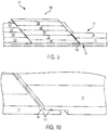
- FIG 9 illustrates an example flooring system 130 in an aircraft 150, according to an example implementation.
- the flooring system 130 includes a first set 132 of floor panels 124 including floor panels 124 attached or rigidly attached to a structure 134 of the aircraft. More specifically, the floor panels 124 of the first set 132 are rigidly attached to the structure 134 by permanent adhesive, screws, bolts, snap-fit, etc.
- the flooring system 130 also includes a second set 136 of floor panels 100, and each floor panel 100 of the second set 136 of floor panels has the interlocking feature 108 for slidably engaging an adjacent floor panel 124 of the first set 132 (further shown in Figure 10 ).
- the interlocking feature 108 is configured to enable lateral relative motion to occur and restrict vertical relative motion between panels 100 of the second set 136 of floor panels 100 and a respective adjacent floor panel 124, for example (described more fully below).
- the second set 136 of floor panels are positioned to define a space 138 between the floor panel 100 and the respective adjacent floor panel 124 to enable the lateral relative motion to occur between panels 100 of the second set of 136 floor panels and the respective adjacent floor panel 124.
- Each floor panel 100 of the second set 136 of floor panels is positioned to engage at least one adjacent floor panel 124 of the first set 132 of floor panels.
- the first set 132 of floor panels is attached to the structure 134 of the aircraft.
- the first set 132 of floor panels can be attached directly to the structure 134 of the aircraft 150 using screws, bolts, snap-fit, and/or any other suitable mechanical fastening device(s).
- Each panel of the first set 132 of floor panels is configured as the floor panel 124 shown in Figure 7
- each panel of the second set 136 of floor panels is configured as the floor panel 100 shown in Figure 1
- a panel of the second set 136 of floor panels has the interlocking feature 108 for slidably engaging an adjacent floor panel 124, which may be a floor panel of the first set 132 of floor panels, as shown in Figure 9 (although other installation configurations exist as described below).
- the flooring system 130 includes the first set 132 of floor panels and the second set 136 of floor panels arranged in alternating rows. Additional configurations of the flooring system 130 are possible and are described below (with reference to Figure 14 ).
- Figure 10 illustrates a magnified view of a portion of the flooring system 130, according to an example implementation.
- the interlocking feature 108 is configured to enable lateral relative motion to occur between panels of the second set 136 of floor panels and a respective adjacent floor panel due to the space 138.
- the panels 100 and 124 move toward and away from each other such that the width of the space 138 changes, for example.
- the interlocking feature 108 is also configured to restrict vertical relative motion between panels of the second set 136 of floor panels and a respective adjacent floor panel due to the interlocking feature 108 of the panel 100 abutting the interlocking feature 108 of the panel 124.
- the flooring system 130 can enable the floor panels 100 of the second set 136 of floor panels to be capable of floating (e.g., free to move with respect to a fixed structure) on the aircraft subfloor (e.g., the structure 134 of the aircraft).
- the floor panel 100 has the interlocking feature 108 that fits with an adjacent floor panel 124 such that the floor panel 100 can float laterally, but the interlocking feature 108 prevents the floor panel 100 from lifting off the subfloor, such as the structure 134.
- the flooring system 130 is configured to withstand determined forces (e.g., about three times the weight of the flooring system 130 of applied force pulling up on the flooring system 130 and about nine times the weight of the flooring system 130 of applied force pulling forward on the flooring system 130).
- the flooring system 130 thus can enable compliance with the mechanics of dynamic loads experienced in the aircraft 150 (e.g., flight loads and thermal contraction at altitude) while maintaining respective floor panels 100, 124 substantially in place (e.g., movable only within an area of the space 138) with respect to each other and the structure 134.
- the flooring system 130 By allowing the floor panels 100 to move relative to adjacent floor panels 124, the flooring system 130 remain substantially in place, but has components that are allowed to float laterally to reduce stress on the flooring system 130 caused by mechanics of aircraft operation.
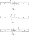
- Figure 11 is a side view of a portion of the flooring system 130 showing the floor panel 100 interlocked with an adjacent floor panel 124.
- the space 138 is present when the two floor panels are interlocked.
- the interlocking feature 108 of each respective floor panel 100, 124 is configured to restrict the vertical relative motion between the floor panel 100 and the floor panel 124 by preventing the floor panel 100 from moving in a direction perpendicular to a surface of the floor panel 100, for example.
- the interlocking feature 108 i.e., a lip
- the interlocking feature 108 i.e., a lip
- Figure 12 is another side view of a portion of the flooring system 130 showing the floor panel 100 interlocked with an adjacent floor panel 124.
- a sealant 142 is positioned into the space 138.
- the sealant 142 may be compressed allowing for the relative lateral motion between the floor panel 100 and the floor panel 124.
- the sealant 142 fills all or substantially all of a volume of the space 138 to prevent any foreign materials or substance from being lodged into the space 138, and to provide a smooth and uniform exterior surface onto which the surface 122 can be positioned.
- Figure 13 is another side view of a portion of the flooring system 130 showing the floor panel 100 interlocked with an adjacent floor panel 124.
- an elastomer insert 144 is positioned into the space 138.
- the elastomer insert 144 may be an extruded rubber piece, for example.
- the elastomer insert 144 may be configured in a "P-shape" (i.e., a shape having a relatively linear portion with a substantially arcuate portion attached to the relatively linear portion) such that a portion (i.e., the relatively linear portion) of the elastomer insert 144 slides underneath the interlocking feature 108 of the floor panel 124 and another portion (i.e., the substantially arcuate portion) of the elastomer insert 144 fills or substantially fills the volume of the space 138.
- the surface 122 is then positioned onto the floor panels 100 and 124 over the elastomer insert 144.
- the relative motion of the floor panels 100 between anchor points (e.g., locations where the floor panels 124 are attached to the structure 134) of the first set 132 of floor panels is absorbed by joints between adjacent panels that can be filled with the sealant 142 (e.g., rubberized sealant) or the elastomer insert 144.
- the sealant 142 e.g., rubberized sealant
- the elastomer insert 144 e.g., rubberized sealant
- Figure 14 illustrates a schematic layout of the flooring system 130 in a portion of an aircraft 150 or another passenger vehicle, according to an example implementation.
- various areas of the aircraft 150 are shown including galley areas and seating areas.
- Figure 14 illustrates a specific layout for a specific aircraft design in which the floor panel 124 is distributed throughout the area in a manner such that all of the floor panels 100 contact and are adjacent to at least one of the floor panels 124 along at least one side or one end. In this way, the floor panel 100 abuts at least one floor panel 124 that is rigidly attached to the structure 134 of the aircraft 150.
- some floor panels 100 of the second set 136 of floor panels are positioned to engage both a respective floor panel 124 of the first set 132 of floor panels and a respective floor panel 100 of the second set 136 of floor panels. This may occur, for example, using a configuration of the floor panel 100 shown in Figure 8 or other specifically configured panels with associated interlocking features 108 in a male/female format as needed.
- FIG 14 some of the floor panels 124 of the first set 132 of floor panels are anchored to the structure 134 of the aircraft 150 at a perimeter area 152 of the aircraft 150. In addition, some of the floor panels 124 of the first set 132 of floor panels are anchored to the structure 134 of the aircraft 150 at one or more door interfaces of the aircraft 150. Locations where the floor panels 124 are attached to the structure 134 can be referred to as "anchor points”. A specific arrangement and location of the floor panels 124 can depend on a design of the aircraft 150.
- the second set 136 of floor panels can be positioned to define the space 138 between the floor panels 100 and the respective adjacent floor panels 124 provided along a perimeter of the second set 136 of floor panels to enable the relative motion to occur both laterally and longitudinally.
- the second set 136 of floor panels can be positioned to define the space 138 between the floor panels 100 and the respective adjacent floor panels 124 provided along one of both sides 111 and 113 of the second set 136 of floor panels or both ends 115 and 117 of the second set 136 of floor panels to enable the relative motion to occur either laterally and longitudinally.
- the interlocking feature 108 of each floor panel 100, 124 is configured to enable relative longitudinal motion to occur between panels 100 of the second set 136 of floor panels and the respective adjacent floor panel 124.
- the space 138 may be in a range of about 0.1 inches (2.54 millimeters) to about 0.2 inches (5.08 millimeters). However, a size of the space 138 can be different from the previously-mentioned range due to a size of the floor panel being used. Further, during use the size of the space 138 can vary as the floor panels 100, 124 move relative to each other.
- Figure 15 shows a flowchart of an example method 200 for installing the flooring system 130 in the aircraft 150, according to an example implementation.
- Method 200 shown in Figure 15 presents an example of a method that could be used with the floor panel 100 and the floor panel 124 shown in Figures 1-8 , and/or the flooring system 130 shown in Figures 9-14 , for example.
- components and/or apparatuses may be configured to be used in the functions such that the components are actually configured and structured to enable such performance.
- components and/or apparatuses may be arranged to be adapted to, capable of, or suited for performance of the functions.
- Method 200 includes one or more operations, functions, or actions as illustrated by one or more of blocks 202-210. Although the blocks are illustrated in a sequential order, these blocks may also be performed in parallel, and/or in a different order than those described herein. Also, the various blocks may be combined into fewer blocks, divided into additional blocks, and/or removed based upon the desired implementation.
- the method 200 includes attaching the first set 132 of floor panels to the structure 134 of the aircraft 150 at locations distributed throughout an area of the aircraft 150.
- the floor panels 124 of the first set 132 are rigidly attached to the structure 134 by permanent adhesive, screws, bolts, snap fit, or bonding or being adhered to the structure 134 in a suitable fashion.
- the method 200 includes positioning the second set 136 of floor panels such that each floor panel of the second set 136 of floor panels is positioned to engage at least one adjacent floor panel of the first set 132 of floor panels.
- Each floor panel of the second set 136 of floor panels has the interlocking feature 108 that slidably engages an adjacent floor panel.
- the interlocking feature 108 is configured to enable lateral relative motion to occur and restrict vertical relative motion between panels of the second set 136 of floor panels and a respective adjacent floor panel.
- the second set 136 of floor panels are positioned to define the space 138 between a respective floor panel 100 of the second set 136 of floor panels and the respective adjacent floor panel 100/124 to enable the lateral relative motion to occur between panels of the second set 136 of floor panels and the respective adjacent floor panel.
- the method can include engaging the floor panels 100 with the adjacent floor panels 124 by interlocking the interlocking features 108 of each respective floor panel so that the interlocking features 108 of respective floor panels abut each other.
- the method 200 includes filling the space 138 with the sealant 142 or the elastomer insert 144.
- the method 200 can include installing a surface 122 onto the first set 132 of floor panels and the second set 136 of floor panels.
- Figure 16 shows a flowchart of additional functions that may be used with or after implementation of the method 200 in Figure 15 .
- additional functions include removing a respective floor panel 100 (or subset of panels) of the second set 136 of floor panels.
- removing a subset of panels can include removing all panels of the flooring system 130 and replacing the removed panels with new floor panels for a new flooring system 130 to change a floor of the passenger vehicle.
- additional functions can include removing a respective floor panel 124 of the first set 132 of floor panels by detaching the respective floor panel 124 from the structure 134.
- additional functions include replacing the respective floor panel 100 of the second set 136 of floor panels with a new floor panel.
- Replacing the respective floor panel 100 can include inserting a new floor panel 100 (or group of panels) into an opening left by removing the respective floor panel 100 (or subset of panels). The insertion of the new floor panel 100 can be made due to the space 138 present between respective panels in the flooring system 130, and by engaging respective interlocking features 108 of the new floor panel 100 with an existing panel in the flooring system 130.
- additional functions can include replacing a respective floor panel 124 of the first set 132 of floor panels with a new floor panel by reattaching the new floor panel to the structure 134.
- Example processes illustrated in the flowcharts in Figure 15 may be performed or carried out manually by a system integrator, a maintenance/repair/overhaul company, other third party, and/or an operator (e.g., an airline or other transport company).
- the example processes illustrated in the flowcharts in Figure 15 can enable a reduced installation time of flooring panels due to less installation materials required and lack of rigid attachment of each individual floor panel of the flooring system 130 to the structure 134 of the aircraft 150. Rather, only panels in the first set 132 of floor panels can be attached to the structure 134 of the aircraft 150.
- the example processes illustrated in the flowcharts in Figure 15 also can enable increased reliability and repeatability of installation, as well as improved aesthetics and customer satisfaction. Furthermore, the example processes illustrated in the flowcharts in Figure 15 can enable increased durability and ability to replace individual panels because the floor panels are not bonded to each other in a permanent manner.
- a non-textile flooring system 130 in commercial passenger aircraft or other vehicle, such as in galley areas of a passenger vehicle, can enable customized aesthetic floor coverings in contrast to the use of generic floor mats.
- examples described herein can avoid issues of buckling of floor coverings because the floor panels are allowed to move relative to each other.
- floor panels of the flooring system 130 described herein may not telegraph, buckle, or blister because the interlocking feature 108 of the floor panels 100 will allow relative lateral motion to occur between the floor panels while ensuring that the floor panels 100 do not lift when an upward load is applied.
- a thin laminate layer is not required over the aircraft subfloor. Rather, floor panels of the flooring system 130 can be directly attached to the structure 134 of the aircraft 150, within examples.
- first, second, etc. are used herein merely as labels, and are not intended to impose ordinal, positional, or hierarchical requirements on the items to which these terms refer. Moreover, reference to, e.g., a “second” item does not require or preclude the existence of, e.g., a "first” or lower-numbered item, and/or, e.g., a "third" or higher-numbered item.
Landscapes
- Engineering & Computer Science (AREA)
- Mechanical Engineering (AREA)
- Architecture (AREA)
- Aviation & Aerospace Engineering (AREA)
- Chemical & Material Sciences (AREA)
- Combustion & Propulsion (AREA)
- Manufacturing & Machinery (AREA)
- Transportation (AREA)
- Structural Engineering (AREA)
- Civil Engineering (AREA)
- Life Sciences & Earth Sciences (AREA)
- Wood Science & Technology (AREA)
- Ocean & Marine Engineering (AREA)
- Floor Finish (AREA)
- Body Structure For Vehicles (AREA)
Claims (12)
- Fußbodensystem (130) für ein Passagierfahrzeug, wobei das Fußbodensystem (130) aufweist:einen ersten Satz (132) von Bodenpaneelen (124) mit Bodenpaneelen (124), die fest mit einer Struktur (134) des Passagierfahrzeugs verbunden sind; und wobei jedes Bodenpaneel (124) aufweisteine Oberplatte (102);eine Bodenplatte (104) entgegengesetzt zu der Oberplatte (102);einen Körper (106), der zwischen der Oberplatte (102) und der Bodenplatte (104) angeordnet ist, mit einem Umfang, der zwei entgegengesetzte Seiten (111, 113) und zwei entgegengesetzte Enden (115, 117) des Bodenpaneels (124) aufweist; undeinem Verschlussmerkmal (108), das sich nach außen von dem Körper (106) erstreckt und das eine Lippe aufweist, die sich nach außen von dem Körper (106) des jeweiligen Bodenpaneels (124) erstreckt,einem zweiten Satz (136) von Bodenpaneelen (100), wobei jedes Bodenpaneel (100) des zweiten Satzes (136) von Bodenpaneelen (100) aufweist:wobei die Lippe der Verschlussmerkmale (108) des Bodenpaneels (124) des ersten Satzes (132) mittels einer Nach-Außen-Erstreckung (109) der Oberplatte (102) über die Bodenplatte (104) ausgebildet ist, so dass die Bodenplatte (104) in Bezug auf das Verschlussmerkmal (108) vorsteht, um einen Sitz (110) zum gleitenden Ineinandergreifen des benachbarten Bodenpaneels (100) und der Lippe der Verschlussmerkmale (108) des Bodenpaneels (100) des zweiten Satzes (136) mittels einer Nach-Außen-Erstreckung (109) der Bodenplatte (104) über die Oberplatte (102) hinaus zu erzeugen, so dass die Oberplatte (102) in Bezug auf das Verschlussmerkmal (108) erhaben ist, um einen Sitz (110) zu erzeugen, der dazu konfiguriert ist, mit dem benachbarten Bodenpaneel (124) ineinanderzugreifen; wobei das Verschlussmerkmal (108) der Bodenpaneele (100, 124) sich auf eine kontinuierliche und ebene Weise entlang zumindest einem Abschnitt eines Umfangs des Körpers (106) entlang beider Seiten (111, 113) und beider Enden (115, 117) des Bodenpaneels (100, 124) erstreckt oder entlang einer der Seiten (111, 113) oder beider Enden (115, 117) des Körpers (106) aber nicht entlang der anderen Seite (113, 111) des Körpers (106) erstreckt;eine Oberplatte (102);eine Bodenplatte (104) entgegengesetzt zu der Oberplatte (102);einen Körper (106), der zwischen der Oberplatte (102) und der Bodenplatte (104) angeordnet ist, mit einem Umfang, der zwei entgegengesetzte Seiten (111, 113) und zwei entgegengesetzte Enden (115, 117) des Bodenpaneels (100) aufweist; undeinem Verschlussmerkmal (108), das sich nach außen von dem Körper (106) erstreckt und das eine Lippe aufweist, die sich nach außen von dem Körper (106) des jeweiligen Bodenpaneels (100) erstreckt,
wobei das Verschlussmerkmal (108) dazu konfiguriert ist, das Auftreten einer lateralen relativen Bewegung zu ermöglichen und eine vertikale relative Bewegung zwischen Paneelen (100) des zweiten Satzes (136) der Bodenpaneele (100) und dem jeweiligen benachbarten Bodenpaneel (124) des ersten Satzes (132) zu beschränken,
wobei im Betrieb der zweite Satz (136) der Bodenpaneele (100) positioniert ist, um einen Zwischenraum (138) zwischen einem jeweiligen Bodenpaneel (100) des zweiten Satzes (136) der Bodenpaneele (100) und dem jeweiligen benachbarten Bodenpaneel (124) des ersten Satzes (132) zu definieren, um die laterale relative Bewegung zu ermöglichen, dass die laterale relative Bewegung zwischen Paneelen (100) des zweiten Satzes (136) von Bodenpaneelen (100) und dem jeweiligen benachbarten Bodenpaneel (124) des ersten Satzes (132) auftritt, und
wobei jedes Bodenpaneel (100) des zweiten Satzes (136) von Bodenpaneelen (100) positioniert ist, um mit zumindest einem benachbarten Bodenpaneel (124) des ersten Satzes (132) von Bodenpaneelen (100) ineinanderzugreifen. - Fußbodensystem (130) nach Anspruch 1, wobei einige Bodenpaneele (100) des zweiten Satzes (136) von Bodenpaneelen (100) positioniert sind, um sowohl ein jeweiliges Paneel (124) des ersten Satzes (132) von Bodenpaneelen (124) und ein jeweiliges Bodenpaneel (100) des zweiten Satzes (136) von Bodenpaneelen (100) ineinanderzugreifen.
- Fußbodensystem (130) nach Anspruch 1 oder 2, wobei das Verschlussmerkmal (108) dazu konfiguriert ist, die vertikale relative Bewegung zwischen Paneelen (100) des zweiten Satzes (136) der Bodenpaneele (100) und dem jeweiligen benachbarten Bodenpaneel (124) zu beschränken, indem vermieden wird, dass die Paneele (100) des zweiten Satzes (136) von Bodenpaneelen (100) sich in eine Richtung senkrecht zu einer Oberfläche (122) der Paneele (100) des zweiten Satzes (136) der Bodenpaneele (100) bewegen.
- Fußbodensystem (130) nach einem der Ansprüche 1-3, wobei das Verschlussmerkmal (108) dazu konfiguriert ist, zu ermöglichen, dass eine relative longitudinale Bewegung zwischen Paneelen (100) des zweiten Satzes (136) von Bodenpaneelen und dem jeweiligen benachbarten Bodenpaneel (124) des ersten Satzes (132) auftritt.
- Fußbodensystem (130) nach Anspruch 1, wobei die Lippe des Bodenpaneels (100) des zweiten Satzes (136) in Anlage eine Lippe des benachbarten Bodenpaneels (124) des ersten Satzes (132) kontaktiert.
- Fußbodensystem (130) nach einem der Ansprüche 1-5, wobei Paneele (124) des ersten Satzes (132) von Bodenpaneelen (124) an der Struktur (134) des Passagierfahrzeugs an einem Bereichsumfang des Passagierfahrzeugs verankert sind.
- Fußbodensystem (130) nach einem der Ansprüche 1-6, wobei Paneele (124) des ersten Satzes (132) von Bodenpaneelen (124) an der Struktur (134) des Passagierfahrzeugs an ein oder mehreren Türschnittstellen des Passagierfahrzeugs verankert sind.
- Fußbodensystem (130) nach einem der Ansprüche 1-7, wobei ein Dichtmittel (142) oder ein Elastomereinsatz (144) in dem Zwischenraum (138) positioniert ist, der zwischen einem jeweiligen Bodenpaneel (100) des zweiten Satzes (136) von Bodenpaneelen (100) und dem jeweiligen benachbarten Bodenpaneel (124) des ersten Satzes (132) definiert ist.
- Fußbodensystem (130) nach einem der Ansprüche 1-8, wobei der Körper (106) von jedem Bodenpaneel (124) des ersten Satzes (132) und jedem Bodenpaneel (100) des zweiten Satzes (136) eine Mehrzahl von Zellen (112) aufweist, die jeweils ein Hohlraum (114) darin aufweisen, der Körper (106).
- Verfahren (200) zum Installieren eines Fußbodensystems in einem Passagierfahrzeug gemäß einem oder mehreren der Ansprüche 1-9, wobei das Verfahren (200) aufweist:Anbringen (202) des ersten Satzes (132) von Bodenpaneelen (124) an einer Struktur des Passagierfahrzeugs an Orten, die durch einen Bereich des Passagierfahrzeugs verteilt sind;Positionieren (204) eines zweiten Satzes (136) von Bodenpaneelen (100), so dass jedes Bodenpaneel des zweiten Satzes (136) von Bodenpaneelen (100) positioniert ist, mit mindestens einem benachbarten Bodenpaneel (124) des ersten Satzes (132) von Bodenpaneelen (124) ineinanderzugreifen, wobei jedes Bodenpaneel (100) des zweiten Satzes (100) von Bodenpaneelen ein Verschlussmerkmal (108) zum gleitenden Ineinandergreifen mit einem benachbarten Bodenpaneel (124) aufweist, wobei das Verschlussmerkmal (108) dazu konfiguriert ist, zu ermöglichen, dass eine laterale relative Bewegung auftritt und eine vertikale relative Bewegung zwischen Bodenpaneelen (100) des zweiten Satzes (136) von Bodenpaneelen und einem jeweiligen benachbarten Bodenpaneel (124) des ersten Satzes (132) zu beschränken, wobei der zweite Satz (136) von Bodenpaneelen (100) positioniert ist, einen Zwischenraum (138) zwischen einem jeweiligen Bodenpaneel (100) des zweiten Satzes (136) von Bodenpaneelen und dem jeweiligen benachbarten Bodenpaneel (124) zu definieren, um zu ermöglichen, dass die laterale relative Bewegung zwischen Paneelen des zweiten Satzes (136) von Bodenpaneelen und dem jeweiligen benachbarten Bodenpaneel auftritt; undFüllen (208) des Zwischenraums mit einem Dichtmittel (142) oder einem Elastomereinsatz (144).
- Verfahren (200) nach Anspruch 10, des Weiteren mit:
Installieren (210) einer Oberfläche auf den ersten Satz (132) von Bodenpaneelen (124) und dem zweiten Satz (136) von Bodenpaneelen (100), wobei die Oberfläche mindestens eines von einer Haftoberfläche und einer Dekoroberfläche aufweist. - Verfahren (200) nach Anspruch 10 oder 11, des Weiteren mit:
In-Eingriff-Bringen (206) vom jedem Bodenpaneel des zweiten Satzes (136) von Bodenpaneelen (100) mit dem mindestens einen benachbarten Bodenpaneel des ersten Satzes (132) von Bodenpaneelen (124) durch Verschließen des Verschlussmerkmals (108) von jedem Bodenpaneel des zweiten Satzes (136) von Bodenpaneelen (100) mit einem Verschlussmerkmal (108) von dem mindestens einen benachbarten Bodenpaneel (124), so dass jeweilige Verschlussmerkmale aneinander anliegen.
Applications Claiming Priority (1)
| Application Number | Priority Date | Filing Date | Title |
|---|---|---|---|
| US15/915,732 US10919612B2 (en) | 2018-03-08 | 2018-03-08 | Floor panels and flooring systems for a passenger vehicle, and methods for installation |
Publications (2)
| Publication Number | Publication Date |
|---|---|
| EP3536603A1 EP3536603A1 (de) | 2019-09-11 |
| EP3536603B1 true EP3536603B1 (de) | 2021-07-07 |
Family
ID=65598429
Family Applications (1)
| Application Number | Title | Priority Date | Filing Date |
|---|---|---|---|
| EP19158756.7A Active EP3536603B1 (de) | 2018-03-08 | 2019-02-22 | Bodenplatten und fussbodensysteme für ein fahrzeug und verfahren zur installation |
Country Status (3)
| Country | Link |
|---|---|
| US (2) | US10919612B2 (de) |
| EP (1) | EP3536603B1 (de) |
| CN (2) | CN117922814A (de) |
Families Citing this family (8)
| Publication number | Priority date | Publication date | Assignee | Title |
|---|---|---|---|---|
| US10919612B2 (en) | 2018-03-08 | 2021-02-16 | The Boeing Company | Floor panels and flooring systems for a passenger vehicle, and methods for installation |
| WO2020072518A1 (en) * | 2018-10-01 | 2020-04-09 | TECHNO-COATINGS, INC. dba TECHNO AEROSPACE | Floating floor attachment system |
| US11225313B2 (en) | 2019-01-28 | 2022-01-18 | Techno-Coatings, Inc. | Spacer assembly for aircraft flooring |
| WO2020160039A1 (en) | 2019-01-28 | 2020-08-06 | Techno-Coatings, Inc. d/b/a Techno Aerospace | Magnetic perimeter attachment for an aircraft flooring section |
| US11518492B2 (en) * | 2019-01-28 | 2022-12-06 | Techno-Coatings, Inc. | Aircraft flooring architecture |
| US11292573B2 (en) * | 2019-04-17 | 2022-04-05 | The Boeing Company | Floor covering systems in a passenger vehicle and methods for installation |
| US20210094621A1 (en) * | 2019-09-26 | 2021-04-01 | International Truck Intellectual Property Company, Llc | Vehicle floor |
| CN113619628B (zh) * | 2020-05-09 | 2022-11-22 | 中车唐山机车车辆有限公司 | 轨道列车的地板系统及轨道列车 |
Family Cites Families (23)
| Publication number | Priority date | Publication date | Assignee | Title |
|---|---|---|---|---|
| US2199938A (en) | 1938-02-10 | 1940-05-07 | Haskelite Mfg Corp | Floor panel for aircraft |
| GB2256023A (en) | 1991-05-18 | 1992-11-25 | Magnet Holdings Ltd | Joint |
| US6675544B1 (en) | 2000-11-28 | 2004-01-13 | J.M. Huber Corporation | Composite wood panels having tongue and groove edges |
| DE10115009C2 (de) * | 2001-03-27 | 2003-05-28 | Lothar Zimmermann | Aufbau eines befahrbaren Industriebodens oder einer Fahrbahn Verfahren zur Herstellung eines befahrbaren Industriebodens oder einer Fahrbahn |
| DE10349790A1 (de) * | 2003-10-24 | 2005-05-25 | Petec S.A. | Bauelement zur Herstellung von Boden- oder Wandverkleidungen |
| DE102004029879B4 (de) | 2004-05-08 | 2023-12-14 | Xylo Technologies Ag | Paneele mit Umrandung insbesondere für Wände und Decken |
| FR2891325B1 (fr) | 2005-09-28 | 2007-10-26 | Airbus France Sas | Dispositif pour la fixation d'un panneau leger sur un support |
| US20110223372A1 (en) | 2006-10-16 | 2011-09-15 | Csp Systems, Inc. | Non-Planar Composite Structural Panel |
| WO2010078822A1 (zh) | 2009-01-06 | 2010-07-15 | Wu Jiamin | 复合金属蜂窝地板 |
| ES2388644T3 (es) * | 2009-01-16 | 2012-10-17 | Flooring Technologies Ltd. | Panel, en particular panel de suelo |
| CA2759394A1 (en) * | 2009-04-27 | 2010-11-11 | Mohawk Carpet Corporation | Flooring systems and methods of making and using same |
| US20110006562A1 (en) * | 2009-07-08 | 2011-01-13 | Specialty Manufacturing, Inc. | Modular floor system for vehicles |
| EP2528736B1 (de) * | 2010-01-28 | 2014-09-17 | Havco Wood Products LLC | Flexible, überlappende verbundstoffverbindung für anhängerböden |
| DE102011111864A1 (de) * | 2011-08-31 | 2013-02-28 | Airbus Operations Gmbh | Abdecksystem für einen Innenraum eines Fahrzeugs, Verfahren zum Abdecken eines Bereichs eines Innenraums eines Fahrzeugs und Fahrzeug mit einem Innenraum, der zumindest bereichsweise durch das Abdecksystem abgedeckt ist |
| US10760283B2 (en) * | 2012-02-23 | 2020-09-01 | Admiral Composite Technologies, Inc. | Deck system and components |
| DE102012204713A1 (de) * | 2012-03-23 | 2013-09-26 | Ford-Werke Gmbh | Ladeboden sowie Profilelement für einen Ladeboden |
| US9539958B2 (en) * | 2012-04-23 | 2017-01-10 | Global Ip Holdings, Llc | Assembly including a compression-molded, composite panel having a cellulose-based core and a hinged mounting flange |
| US9981446B2 (en) * | 2013-09-03 | 2018-05-29 | The Boeing Company | Structural inserts for honeycomb structures |
| EP3060470B1 (de) * | 2013-10-21 | 2020-06-03 | B/E Aerospace, Inc. | Modulares anpassungssystem für bodenschienen in flugzeugen |
| WO2016120755A1 (en) * | 2015-01-30 | 2016-08-04 | Bombardier Inc. | Conductive sealing member |
| DE102015104230B4 (de) * | 2015-03-20 | 2017-07-13 | Telair International Gmbh | Montageeinrichtung |
| CN107640311A (zh) * | 2016-07-21 | 2018-01-30 | 江苏辛巴地板有限公司 | 一种航天用塑木复合地板 |
| US10919612B2 (en) | 2018-03-08 | 2021-02-16 | The Boeing Company | Floor panels and flooring systems for a passenger vehicle, and methods for installation |
-
2018
- 2018-03-08 US US15/915,732 patent/US10919612B2/en active Active
-
2019
- 2019-02-22 CN CN202410126040.4A patent/CN117922814A/zh active Pending
- 2019-02-22 EP EP19158756.7A patent/EP3536603B1/de active Active
- 2019-02-22 CN CN201910132558.8A patent/CN110239703B/zh active Active
-
2021
- 2021-01-28 US US17/160,972 patent/US11524763B2/en active Active
Non-Patent Citations (1)
| Title |
|---|
| None * |
Also Published As
| Publication number | Publication date |
|---|---|
| US20190276133A1 (en) | 2019-09-12 |
| US11524763B2 (en) | 2022-12-13 |
| CN110239703B (zh) | 2024-02-27 |
| US20210147059A1 (en) | 2021-05-20 |
| EP3536603A1 (de) | 2019-09-11 |
| US10919612B2 (en) | 2021-02-16 |
| BR102019004389A2 (pt) | 2019-10-01 |
| CN117922814A (zh) | 2024-04-26 |
| CN110239703A (zh) | 2019-09-17 |
Similar Documents
| Publication | Publication Date | Title |
|---|---|---|
| EP3536603B1 (de) | Bodenplatten und fussbodensysteme für ein fahrzeug und verfahren zur installation | |
| EP3725670B1 (de) | Bodenbelagssysteme in einem flugzeug und verfahren zur installation | |
| US8534023B2 (en) | Self locking flooring panels and related methods | |
| US8984838B2 (en) | Kit and assembly for compensating for coefficients of thermal expansion of decorative mounted panels | |
| US8037656B2 (en) | Flooring boards with press down locking mechanism | |
| JP4642781B2 (ja) | 床用のカバー及びロッキングシステム、及び、例えば床板を製造する装置 | |
| EP1971736B1 (de) | Feuchtigkeitsbeständiger Satz von Bodenplatten und Fußboden | |
| US10392811B2 (en) | Building element in plate shape, in particular floor covering panel, as well as floor covering formed by using said building elements, and method for their arrangement | |
| EP3243649A1 (de) | Verfahren und vorrichtung zur kopplung eines dekorativen verbundstoffs mit einer verstärkungsschicht an eine platte | |
| US9556620B2 (en) | Floor panel for forming a floor covering, floor covering formed of such floor panels, and method for manufacturing such floor panels | |
| US20100281810A1 (en) | Overlap System For A Flooring System | |
| US20150113908A1 (en) | Floating floor system, floor panel, and installation method for the same | |
| US9518393B2 (en) | Kit and assembly for compensating for coefficients of thermal expansion of decorative mounted panels | |
| CA2453599A1 (en) | Floor panels with sealing means | |
| CN113356508A (zh) | 镶板 | |
| EP3243656A1 (de) | Verfahren und vorrichtung zum verbinden einer dekorschicht mit einer platte über eine klebeschicht mit hoher bindung | |
| US20130048785A1 (en) | Covering system for an interior space of a vehicle, a method for covering a region of an interior space of a vehicle, and a vehicle with an interior space, which is covered by the covering system in at least some regions | |
| CA3164422A1 (en) | Panel comprising coupling parts | |
| EP4341151B1 (de) | Überlagerungsboden für kraftfahrzeuge | |
| CN111186559A (zh) | 飞行器地板结构 | |
| WO2020160036A1 (en) | Spacer assembly for aircraft flooring | |
| BR102019004389B1 (pt) | Sistema de pavimentação, e, método para instalar um sistema de pavimentação | |
| EP3243977A2 (de) | Harte fussboden- oder wandpaneelplanke | |
| JP2025027974A (ja) | 航空機内の床材用敷居 | |
| CA2589586A1 (en) | Surface covering systems |
Legal Events
| Date | Code | Title | Description |
|---|---|---|---|
| PUAI | Public reference made under article 153(3) epc to a published international application that has entered the european phase |
Free format text: ORIGINAL CODE: 0009012 |
|
| STAA | Information on the status of an ep patent application or granted ep patent |
Free format text: STATUS: REQUEST FOR EXAMINATION WAS MADE |
|
| STAA | Information on the status of an ep patent application or granted ep patent |
Free format text: STATUS: EXAMINATION IS IN PROGRESS |
|
| 17P | Request for examination filed |
Effective date: 20190222 |
|
| AK | Designated contracting states |
Kind code of ref document: A1 Designated state(s): AL AT BE BG CH CY CZ DE DK EE ES FI FR GB GR HR HU IE IS IT LI LT LU LV MC MK MT NL NO PL PT RO RS SE SI SK SM TR |
|
| AX | Request for extension of the european patent |
Extension state: BA ME |
|
| 17Q | First examination report despatched |
Effective date: 20190820 |
|
| GRAP | Despatch of communication of intention to grant a patent |
Free format text: ORIGINAL CODE: EPIDOSNIGR1 |
|
| STAA | Information on the status of an ep patent application or granted ep patent |
Free format text: STATUS: GRANT OF PATENT IS INTENDED |
|
| INTG | Intention to grant announced |
Effective date: 20201204 |
|
| GRAJ | Information related to disapproval of communication of intention to grant by the applicant or resumption of examination proceedings by the epo deleted |
Free format text: ORIGINAL CODE: EPIDOSDIGR1 |
|
| STAA | Information on the status of an ep patent application or granted ep patent |
Free format text: STATUS: EXAMINATION IS IN PROGRESS |
|
| GRAJ | Information related to disapproval of communication of intention to grant by the applicant or resumption of examination proceedings by the epo deleted |
Free format text: ORIGINAL CODE: EPIDOSDIGR1 |
|
| GRAP | Despatch of communication of intention to grant a patent |
Free format text: ORIGINAL CODE: EPIDOSNIGR1 |
|
| GRAS | Grant fee paid |
Free format text: ORIGINAL CODE: EPIDOSNIGR3 |
|
| INTC | Intention to grant announced (deleted) | ||
| GRAS | Grant fee paid |
Free format text: ORIGINAL CODE: EPIDOSNIGR3 |
|
| STAA | Information on the status of an ep patent application or granted ep patent |
Free format text: STATUS: GRANT OF PATENT IS INTENDED |
|
| GRAP | Despatch of communication of intention to grant a patent |
Free format text: ORIGINAL CODE: EPIDOSNIGR1 |
|
| INTG | Intention to grant announced |
Effective date: 20210514 |
|
| GRAA | (expected) grant |
Free format text: ORIGINAL CODE: 0009210 |
|
| STAA | Information on the status of an ep patent application or granted ep patent |
Free format text: STATUS: THE PATENT HAS BEEN GRANTED |
|
| AK | Designated contracting states |
Kind code of ref document: B1 Designated state(s): AL AT BE BG CH CY CZ DE DK EE ES FI FR GB GR HR HU IE IS IT LI LT LU LV MC MK MT NL NO PL PT RO RS SE SI SK SM TR |
|
| REG | Reference to a national code |
Ref country code: GB Ref legal event code: FG4D |
|
| REG | Reference to a national code |
Ref country code: AT Ref legal event code: REF Ref document number: 1408361 Country of ref document: AT Kind code of ref document: T Effective date: 20210715 |
|
| REG | Reference to a national code |
Ref country code: DE Ref legal event code: R096 Ref document number: 602019005812 Country of ref document: DE |
|
| REG | Reference to a national code |
Ref country code: IE Ref legal event code: FG4D |
|
| REG | Reference to a national code |
Ref country code: LT Ref legal event code: MG9D |
|
| REG | Reference to a national code |
Ref country code: NL Ref legal event code: MP Effective date: 20210707 |
|
| REG | Reference to a national code |
Ref country code: AT Ref legal event code: MK05 Ref document number: 1408361 Country of ref document: AT Kind code of ref document: T Effective date: 20210707 |
|
| PG25 | Lapsed in a contracting state [announced via postgrant information from national office to epo] |
Ref country code: BG Free format text: LAPSE BECAUSE OF FAILURE TO SUBMIT A TRANSLATION OF THE DESCRIPTION OR TO PAY THE FEE WITHIN THE PRESCRIBED TIME-LIMIT Effective date: 20211007 Ref country code: AT Free format text: LAPSE BECAUSE OF FAILURE TO SUBMIT A TRANSLATION OF THE DESCRIPTION OR TO PAY THE FEE WITHIN THE PRESCRIBED TIME-LIMIT Effective date: 20210707 Ref country code: LT Free format text: LAPSE BECAUSE OF FAILURE TO SUBMIT A TRANSLATION OF THE DESCRIPTION OR TO PAY THE FEE WITHIN THE PRESCRIBED TIME-LIMIT Effective date: 20210707 Ref country code: NL Free format text: LAPSE BECAUSE OF FAILURE TO SUBMIT A TRANSLATION OF THE DESCRIPTION OR TO PAY THE FEE WITHIN THE PRESCRIBED TIME-LIMIT Effective date: 20210707 Ref country code: PT Free format text: LAPSE BECAUSE OF FAILURE TO SUBMIT A TRANSLATION OF THE DESCRIPTION OR TO PAY THE FEE WITHIN THE PRESCRIBED TIME-LIMIT Effective date: 20211108 Ref country code: NO Free format text: LAPSE BECAUSE OF FAILURE TO SUBMIT A TRANSLATION OF THE DESCRIPTION OR TO PAY THE FEE WITHIN THE PRESCRIBED TIME-LIMIT Effective date: 20211007 Ref country code: HR Free format text: LAPSE BECAUSE OF FAILURE TO SUBMIT A TRANSLATION OF THE DESCRIPTION OR TO PAY THE FEE WITHIN THE PRESCRIBED TIME-LIMIT Effective date: 20210707 Ref country code: RS Free format text: LAPSE BECAUSE OF FAILURE TO SUBMIT A TRANSLATION OF THE DESCRIPTION OR TO PAY THE FEE WITHIN THE PRESCRIBED TIME-LIMIT Effective date: 20210707 Ref country code: SE Free format text: LAPSE BECAUSE OF FAILURE TO SUBMIT A TRANSLATION OF THE DESCRIPTION OR TO PAY THE FEE WITHIN THE PRESCRIBED TIME-LIMIT Effective date: 20210707 Ref country code: ES Free format text: LAPSE BECAUSE OF FAILURE TO SUBMIT A TRANSLATION OF THE DESCRIPTION OR TO PAY THE FEE WITHIN THE PRESCRIBED TIME-LIMIT Effective date: 20210707 Ref country code: FI Free format text: LAPSE BECAUSE OF FAILURE TO SUBMIT A TRANSLATION OF THE DESCRIPTION OR TO PAY THE FEE WITHIN THE PRESCRIBED TIME-LIMIT Effective date: 20210707 |
|
| PG25 | Lapsed in a contracting state [announced via postgrant information from national office to epo] |
Ref country code: PL Free format text: LAPSE BECAUSE OF FAILURE TO SUBMIT A TRANSLATION OF THE DESCRIPTION OR TO PAY THE FEE WITHIN THE PRESCRIBED TIME-LIMIT Effective date: 20210707 Ref country code: LV Free format text: LAPSE BECAUSE OF FAILURE TO SUBMIT A TRANSLATION OF THE DESCRIPTION OR TO PAY THE FEE WITHIN THE PRESCRIBED TIME-LIMIT Effective date: 20210707 Ref country code: GR Free format text: LAPSE BECAUSE OF FAILURE TO SUBMIT A TRANSLATION OF THE DESCRIPTION OR TO PAY THE FEE WITHIN THE PRESCRIBED TIME-LIMIT Effective date: 20211008 |
|
| REG | Reference to a national code |
Ref country code: DE Ref legal event code: R097 Ref document number: 602019005812 Country of ref document: DE |
|
| PG25 | Lapsed in a contracting state [announced via postgrant information from national office to epo] |
Ref country code: DK Free format text: LAPSE BECAUSE OF FAILURE TO SUBMIT A TRANSLATION OF THE DESCRIPTION OR TO PAY THE FEE WITHIN THE PRESCRIBED TIME-LIMIT Effective date: 20210707 |
|
| PLBE | No opposition filed within time limit |
Free format text: ORIGINAL CODE: 0009261 |
|
| STAA | Information on the status of an ep patent application or granted ep patent |
Free format text: STATUS: NO OPPOSITION FILED WITHIN TIME LIMIT |
|
| PG25 | Lapsed in a contracting state [announced via postgrant information from national office to epo] |
Ref country code: SM Free format text: LAPSE BECAUSE OF FAILURE TO SUBMIT A TRANSLATION OF THE DESCRIPTION OR TO PAY THE FEE WITHIN THE PRESCRIBED TIME-LIMIT Effective date: 20210707 Ref country code: SK Free format text: LAPSE BECAUSE OF FAILURE TO SUBMIT A TRANSLATION OF THE DESCRIPTION OR TO PAY THE FEE WITHIN THE PRESCRIBED TIME-LIMIT Effective date: 20210707 Ref country code: RO Free format text: LAPSE BECAUSE OF FAILURE TO SUBMIT A TRANSLATION OF THE DESCRIPTION OR TO PAY THE FEE WITHIN THE PRESCRIBED TIME-LIMIT Effective date: 20210707 Ref country code: EE Free format text: LAPSE BECAUSE OF FAILURE TO SUBMIT A TRANSLATION OF THE DESCRIPTION OR TO PAY THE FEE WITHIN THE PRESCRIBED TIME-LIMIT Effective date: 20210707 Ref country code: CZ Free format text: LAPSE BECAUSE OF FAILURE TO SUBMIT A TRANSLATION OF THE DESCRIPTION OR TO PAY THE FEE WITHIN THE PRESCRIBED TIME-LIMIT Effective date: 20210707 Ref country code: AL Free format text: LAPSE BECAUSE OF FAILURE TO SUBMIT A TRANSLATION OF THE DESCRIPTION OR TO PAY THE FEE WITHIN THE PRESCRIBED TIME-LIMIT Effective date: 20210707 |
|
| 26N | No opposition filed |
Effective date: 20220408 |
|
| PG25 | Lapsed in a contracting state [announced via postgrant information from national office to epo] |
Ref country code: IT Free format text: LAPSE BECAUSE OF FAILURE TO SUBMIT A TRANSLATION OF THE DESCRIPTION OR TO PAY THE FEE WITHIN THE PRESCRIBED TIME-LIMIT Effective date: 20210707 |
|
| PG25 | Lapsed in a contracting state [announced via postgrant information from national office to epo] |
Ref country code: MC Free format text: LAPSE BECAUSE OF FAILURE TO SUBMIT A TRANSLATION OF THE DESCRIPTION OR TO PAY THE FEE WITHIN THE PRESCRIBED TIME-LIMIT Effective date: 20210707 |
|
| REG | Reference to a national code |
Ref country code: CH Ref legal event code: PL |
|
| REG | Reference to a national code |
Ref country code: BE Ref legal event code: MM Effective date: 20220228 |
|
| PG25 | Lapsed in a contracting state [announced via postgrant information from national office to epo] |
Ref country code: LU Free format text: LAPSE BECAUSE OF NON-PAYMENT OF DUE FEES Effective date: 20220222 |
|
| PG25 | Lapsed in a contracting state [announced via postgrant information from national office to epo] |
Ref country code: LI Free format text: LAPSE BECAUSE OF NON-PAYMENT OF DUE FEES Effective date: 20220228 Ref country code: IE Free format text: LAPSE BECAUSE OF NON-PAYMENT OF DUE FEES Effective date: 20220222 Ref country code: CH Free format text: LAPSE BECAUSE OF NON-PAYMENT OF DUE FEES Effective date: 20220228 |
|
| PG25 | Lapsed in a contracting state [announced via postgrant information from national office to epo] |
Ref country code: BE Free format text: LAPSE BECAUSE OF NON-PAYMENT OF DUE FEES Effective date: 20220228 |
|
| P01 | Opt-out of the competence of the unified patent court (upc) registered |
Effective date: 20230516 |
|
| PG25 | Lapsed in a contracting state [announced via postgrant information from national office to epo] |
Ref country code: MK Free format text: LAPSE BECAUSE OF FAILURE TO SUBMIT A TRANSLATION OF THE DESCRIPTION OR TO PAY THE FEE WITHIN THE PRESCRIBED TIME-LIMIT Effective date: 20210707 Ref country code: CY Free format text: LAPSE BECAUSE OF FAILURE TO SUBMIT A TRANSLATION OF THE DESCRIPTION OR TO PAY THE FEE WITHIN THE PRESCRIBED TIME-LIMIT Effective date: 20210707 |
|
| PG25 | Lapsed in a contracting state [announced via postgrant information from national office to epo] |
Ref country code: HU Free format text: LAPSE BECAUSE OF FAILURE TO SUBMIT A TRANSLATION OF THE DESCRIPTION OR TO PAY THE FEE WITHIN THE PRESCRIBED TIME-LIMIT; INVALID AB INITIO Effective date: 20190222 |
|
| PG25 | Lapsed in a contracting state [announced via postgrant information from national office to epo] |
Ref country code: MT Free format text: LAPSE BECAUSE OF FAILURE TO SUBMIT A TRANSLATION OF THE DESCRIPTION OR TO PAY THE FEE WITHIN THE PRESCRIBED TIME-LIMIT Effective date: 20210707 |
|
| PG25 | Lapsed in a contracting state [announced via postgrant information from national office to epo] |
Ref country code: TR Free format text: LAPSE BECAUSE OF FAILURE TO SUBMIT A TRANSLATION OF THE DESCRIPTION OR TO PAY THE FEE WITHIN THE PRESCRIBED TIME-LIMIT Effective date: 20210707 |
|
| PGFP | Annual fee paid to national office [announced via postgrant information from national office to epo] |
Ref country code: GB Payment date: 20260227 Year of fee payment: 8 |
|
| PGFP | Annual fee paid to national office [announced via postgrant information from national office to epo] |
Ref country code: DE Payment date: 20260227 Year of fee payment: 8 |
|
| PGFP | Annual fee paid to national office [announced via postgrant information from national office to epo] |
Ref country code: FR Payment date: 20260225 Year of fee payment: 8 |