EP3536612A1 - Drone doté d'un coussin de sécurité gonflable - Google Patents
Drone doté d'un coussin de sécurité gonflable Download PDFInfo
- Publication number
- EP3536612A1 EP3536612A1 EP17868210.0A EP17868210A EP3536612A1 EP 3536612 A1 EP3536612 A1 EP 3536612A1 EP 17868210 A EP17868210 A EP 17868210A EP 3536612 A1 EP3536612 A1 EP 3536612A1
- Authority
- EP
- European Patent Office
- Prior art keywords
- airbag
- drone
- inflation
- central mounting
- things
- Prior art date
- Legal status (The legal status is an assumption and is not a legal conclusion. Google has not performed a legal analysis and makes no representation as to the accuracy of the status listed.)
- Granted
Links
Images









Classifications
-
- B—PERFORMING OPERATIONS; TRANSPORTING
- B60—VEHICLES IN GENERAL
- B60R—VEHICLES, VEHICLE FITTINGS, OR VEHICLE PARTS, NOT OTHERWISE PROVIDED FOR
- B60R21/00—Arrangements or fittings on vehicles for protecting or preventing injuries to occupants or pedestrians in case of accidents or other traffic risks
- B60R21/34—Protecting non-occupants of a vehicle, e.g. pedestrians
- B60R21/36—Protecting non-occupants of a vehicle, e.g. pedestrians using airbags
-
- B—PERFORMING OPERATIONS; TRANSPORTING
- B64—AIRCRAFT; AVIATION; COSMONAUTICS
- B64D—EQUIPMENT FOR FITTING IN OR TO AIRCRAFT; FLIGHT SUITS; PARACHUTES; ARRANGEMENT OR MOUNTING OF POWER PLANTS OR PROPULSION TRANSMISSIONS IN AIRCRAFT
- B64D45/00—Aircraft indicators or protectors not otherwise provided for
- B64D45/04—Landing aids; Safety measures to prevent collision with earth's surface
-
- B—PERFORMING OPERATIONS; TRANSPORTING
- B60—VEHICLES IN GENERAL
- B60R—VEHICLES, VEHICLE FITTINGS, OR VEHICLE PARTS, NOT OTHERWISE PROVIDED FOR
- B60R21/00—Arrangements or fittings on vehicles for protecting or preventing injuries to occupants or pedestrians in case of accidents or other traffic risks
- B60R21/02—Occupant safety arrangements or fittings, e.g. crash pads
- B60R21/16—Inflatable occupant restraints or confinements designed to inflate upon impact or impending impact, e.g. air bags
- B60R21/23—Inflatable members
- B60R21/237—Inflatable members characterised by the way they are folded
-
- B—PERFORMING OPERATIONS; TRANSPORTING
- B64—AIRCRAFT; AVIATION; COSMONAUTICS
- B64C—AEROPLANES; HELICOPTERS
- B64C27/00—Rotorcraft; Rotors peculiar thereto
- B64C27/006—Safety devices
-
- B—PERFORMING OPERATIONS; TRANSPORTING
- B64—AIRCRAFT; AVIATION; COSMONAUTICS
- B64C—AEROPLANES; HELICOPTERS
- B64C39/00—Aircraft not otherwise provided for
- B64C39/02—Aircraft not otherwise provided for characterised by special use
-
- B—PERFORMING OPERATIONS; TRANSPORTING
- B64—AIRCRAFT; AVIATION; COSMONAUTICS
- B64D—EQUIPMENT FOR FITTING IN OR TO AIRCRAFT; FLIGHT SUITS; PARACHUTES; ARRANGEMENT OR MOUNTING OF POWER PLANTS OR PROPULSION TRANSMISSIONS IN AIRCRAFT
- B64D45/00—Aircraft indicators or protectors not otherwise provided for
- B64D45/04—Landing aids; Safety measures to prevent collision with earth's surface
- B64D45/06—Landing aids; Safety measures to prevent collision with earth's surface mechanical
-
- B—PERFORMING OPERATIONS; TRANSPORTING
- B64—AIRCRAFT; AVIATION; COSMONAUTICS
- B64U—UNMANNED AERIAL VEHICLES [UAV]; EQUIPMENT THEREFOR
- B64U20/00—Constructional aspects of UAVs
- B64U20/30—Constructional aspects of UAVs for safety, e.g. with frangible components
-
- B—PERFORMING OPERATIONS; TRANSPORTING
- B64—AIRCRAFT; AVIATION; COSMONAUTICS
- B64U—UNMANNED AERIAL VEHICLES [UAV]; EQUIPMENT THEREFOR
- B64U70/00—Launching, take-off or landing arrangements
- B64U70/80—Vertical take-off or landing, e.g. using rockets
- B64U70/83—Vertical take-off or landing, e.g. using rockets using parachutes, balloons or the like
-
- B—PERFORMING OPERATIONS; TRANSPORTING
- B64—AIRCRAFT; AVIATION; COSMONAUTICS
- B64D—EQUIPMENT FOR FITTING IN OR TO AIRCRAFT; FLIGHT SUITS; PARACHUTES; ARRANGEMENT OR MOUNTING OF POWER PLANTS OR PROPULSION TRANSMISSIONS IN AIRCRAFT
- B64D2201/00—Airbags mounted in aircraft for any use
-
- B—PERFORMING OPERATIONS; TRANSPORTING
- B64—AIRCRAFT; AVIATION; COSMONAUTICS
- B64D—EQUIPMENT FOR FITTING IN OR TO AIRCRAFT; FLIGHT SUITS; PARACHUTES; ARRANGEMENT OR MOUNTING OF POWER PLANTS OR PROPULSION TRANSMISSIONS IN AIRCRAFT
- B64D25/00—Emergency apparatus or devices, not otherwise provided for
-
- B—PERFORMING OPERATIONS; TRANSPORTING
- B64—AIRCRAFT; AVIATION; COSMONAUTICS
- B64D—EQUIPMENT FOR FITTING IN OR TO AIRCRAFT; FLIGHT SUITS; PARACHUTES; ARRANGEMENT OR MOUNTING OF POWER PLANTS OR PROPULSION TRANSMISSIONS IN AIRCRAFT
- B64D45/00—Aircraft indicators or protectors not otherwise provided for
-
- B—PERFORMING OPERATIONS; TRANSPORTING
- B64—AIRCRAFT; AVIATION; COSMONAUTICS
- B64U—UNMANNED AERIAL VEHICLES [UAV]; EQUIPMENT THEREFOR
- B64U10/00—Type of UAV
- B64U10/10—Rotorcrafts
- B64U10/13—Flying platforms
- B64U10/14—Flying platforms with four distinct rotor axes, e.g. quadcopters
-
- B—PERFORMING OPERATIONS; TRANSPORTING
- B64—AIRCRAFT; AVIATION; COSMONAUTICS
- B64U—UNMANNED AERIAL VEHICLES [UAV]; EQUIPMENT THEREFOR
- B64U30/00—Means for producing lift; Empennages; Arrangements thereof
- B64U30/20—Rotors; Rotor supports
Definitions
- the present invention relates to a drone with an airbag. More particularly, the present invention relates to a drone with an airbag in which the airbag can be inflated before the drone collides with the other things such as a person or an initially inflated airbag is provided, in such a manner as to effectively prevent such a danger that the drone injures the person in the case that the drone collides with the other things such as the person or a building structure, when the drone during the flight becomes an uncontrollable state under the influence of a trouble in an air frame, an abnormal weather or a radio disturbance and is crashed.
- the drone in which an arm part is protruded from a central mounting part accommodating a camera therein, and a rotary vane is provided at a front side position of the arm part, the drone may be crashed by the trouble of the air frame such as a breakage of a motor rotating the rotary vane and a deterioration of a battery, or may be crashed under the influence of the abnormal weather such as blast, and may be further crushed by the radio disturbance in the case that the drone is affected by any noise or flies to an area where the radio wave does not reach, that is, the drone may be crashed due to various causes (patent literature 1 and patent literature 2).
- the present invention is developed by taking into consideration the conventional problems mentioned above, and an object of the present invention is to provide a drone with an airbag which can effectively prevent such the danger that the drone during the flight is crashed due to the unexpected occurrence such as the trouble in the air fame, the abnormal weather and the radio wave, and the crashed drone collides with the other things such as the person or the building structure and injures the person.
- the present invention employs the following means.
- the drone provided with a rotary vane generating a lift force is provided with the airbag which absorbs a shock generated when the drone is crashed and collides with the other things, and is provided with an inflation control device which controls inflation of the airbag, the airbag can inflate by the gas supplied on the basis of a control by the inflation control device, and the inflation is carried out by the control before the drone collides with the other things.
- the airbag includes a second airbag which absorbs the shock generated when the drone is crashed and collides with the other things, and is provided with a second inflation control device which controls the inflation of the second airbag.
- the second airbag can inflate by the gas supplied on the basis of the control by the second inflation control device, the inflation is carried out by the control before the drone collides with the other things, and the inflating second airbag surrounds the drone like a ring in a vertical plane.
- the drone provided with a rotary vane generating a lift force is provided with a first airbag which absorbs a shock generated when the drone is crashed and collides with the other things, and is provided with a first inflation control device which controls inflation of the first airbag, the first airbag can inflate by the gas supplied on the basis of a control by the first inflation control device, the inflation is carried out by the control before the drone collides with the other things, and the inflating first airbag surrounds the drone in a horizontal plane.
- the drone with the airbag is provided with a second airbag which absorbs the shock generated when the drone is crashed and collides with the other things, and is provided with a second inflation control device which controls the inflation of the second airbag.
- the second airbag can inflate by the gas supplied by the control of the second inflation control device, the inflation is carried out by the control before the drone collides with the other things, and the inflating second airbag surrounds the drone like a ring in a vertical plane.
- the drone provided with a rotary vane generating a lift force is provided with a first airbag which absorbs a shock generated when the drone is crashed and collides with the other things, and is provided with a first inflation control device which controls inflation of the first airbag.
- the drone is provided with an arm part which is protruded from a central mounting part in a radial pattern, or one arm part or a plurality of arm parts which are protruded in each of right and left sides of the central mounting part, and the rotary vane generating the lift force by rotation thereof is provided at a front side position of the arm part.
- the first airbag is held by a first holding part which is substantially provided in the central mounting part, the first holding part is provided in a folded state with the first airbag which can inflate by the gas supplied by the control of the first inflation control device, and the inflating first airbag is adapted to inflate outward from the first holding part as seen in the horizontal plane. Further, the inflation is carried out by the control before the drone collides with the other things, and the inflating first airbag surrounds the drone in the horizontal plate while putting the central mounting part in the center.
- the drone with the airbag is provided with a second airbag which absorbs the shock generated when the drone is crashed and collides with the other things, and is provided with a second inflation control device which controls inflation of the second airbag, and the second airbag is held by a second holding part which is substantially provided in the central mounting part.
- the second holding part is provided in a folded state with the second airbag which can inflate by the gas supplied by the control of the second inflation control device, the inflating second airbag is adapted to inflate so as to protrude outward from the second holding part as seen in the vertical plane, the inflation is carried out by the control before the drone collides with the other things, and the inflating second airbag surrounds the drone like a ring in the vertical plane while putting the central mounting part in the center.
- a fourth aspect of the drone with the airbag according to the present invention is the second aspect mentioned above, wherein the first airbag surrounds the drone like a ring within the horizontal plane while putting the central mounting part in the center.
- a fifth aspect of the drone with the airbag according to the present invention is the third aspect, wherein the first airbag surrounds the drone like a ring in the horizontal plane while putting the central mounting part in the center.
- the drone provided with a rotary vane generating a lift force is provided with a first airbag which absorbs a shock generated when the drone is crashed and collides with the other things, and is provided with a first inflation control device which controls inflation of the first airbag, the drone is provided with an arm part which is protruded from a central mounting part in a radial pattern, or one arm part or a plurality of arm parts which are protruded in each of right and left sides of the central mounting part, and the rotary vane generating the lift force by rotation thereof is provided at a front side position of the arm part.
- the first airbag is held by a first holding part which is substantially provided in the central mounting part.
- the first holding part is provided in a folded state with the first airbag which can inflate by the gas supplied by the control of the first inflation control device, the inflating first airbag is adapted to inflate so as to protrude outward from the first holding part as seen in the horizontal plane, the inflation is carried out by the control before the drone collides with the other things, and the inflating first airbag surrounds the drone in the horizontal plane while putting the central mounting part in the center.
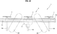
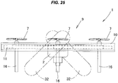
- the drone with the airbag is additionally provided with a second airbag which absorbs the shock when the drone is crashed and collides with the other things, and is provided with a second inflation control device which controls inflation of the second airbag, the second airbag is constructed by two second airbags, these two second airbags can inflate in such a manner as to pinch the central mounting part in a crossing state, and each of the second airbags is held by a second holding part which is substantially provided in the central mounting part.
- the second holding part is provided in a folded state with the second airbag which can inflate by the gas supplied by the control of the second inflation control device, the inflating second airbag is adapted to pinch the central mounting part in the crossing state, the inflation is carried out by the control before the drone collides with the other things, and the inflating second airbag pinches the central mounting part in the crossing state.
- a seventh aspect of the drone with the airbag according to the present invention is the drone with the airbag according to any one of the second to sixth aspects, wherein the first airbag is adapted to inflate so as to protrude long upward and/or downward at the same time as inflating so as to protrude outward as seen in the horizontal plane by the supply of the gas.
- An eighth aspect of the drone with the airbag according to the present invention is the drone with the air bag according to any one of the second to sixth aspects, wherein the first airbag is adapted to inflate so as to protrude long at least downward at the same time as inflating so as to protrude outward as seen in the horizontal plane by the supply of the gas.
- a ninth aspect of the drone with the airbag according to the present invention is the drone with the air bag according to any one of the first to fifth aspects, wherein the second airbag is adapted to inflate so as to protrude long to one side and/or the other side as seen in the surface which is orthogonal to the vertical plane, at the same time as inflating so as to protrude outward as seen in the vertical plane by the supply of the gas.
- a tenth aspect of the drone with the airbag according to the present invention is the drone with the air bag according to the third or sixth aspect, wherein the first holding part is connected to a front end part of a first support part which is protruded in the central mounting part, and the first holding part is thereby provided substantially in the central mounting part.
- An eleventh aspect of the drone with the airbag according to the present invention is the drone with the air bag according to the third or sixth aspect, wherein the first holding part is connected to a first support part serving as a protective frame which surrounds the rotary vane for protecting the rotary vane, and the first holding part is thereby provided substantially in the central mounting part.
- a twelfth aspect of the drone with the airbag according to the present invention is the drone with the air bag according to the third or sixth aspect, wherein the first holding part is connected to a first support part serving as a protective frame which surrounds the rotary vane in its outer side, and the first holding part is thereby provided substantially in the central mounting part.
- the drone with the airbag according to the present invention it is possible to effectively prevent the danger that the drone injures the person in the case that the drone collides with the other things such as the person or the building structure, when the drone during the flight becomes an uncontrollable state under the influence of the trouble in the air frame, the abnormal weather or the radio disturbance and is crashed.
- a drone with airbag 1 is structured such that a drone 9 having rotary vanes 7 generating lift force is provided with an airbag 8 which absorbs a shock when the drone 9 is crashed and collides with the other things such as a person and a building structure, and an inflation control device controlling inflation of the airbag 8 is provided.
- the airbag 8 can be inflated by gas supplied on the basis of a control by the inflation control device, and the inflation is carried out before the drone 9 collides with the other things according to the control.
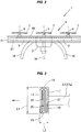
- the drone 9 is structured such that arm parts 3 are protruded out of a central mounting part 2 in a radial pattern, and the rotary vane 7 which can rotate around a vertical axis 6 ( Fig. 2 ) is provided in a front side position 5 of each of the arm parts 3.
- a first holding part 10 is provided in such a manner as to surround the drone 9 while putting the central mounting part 2 at the center.
- a first airbag 11 (one aspect of the airbag 8) which can be inflated by the supplied gas is attached to the first holding part 10 in a folded state, as shown in Figs. 2 to 3 .
- the first airbag 11 is adapted to be inflated so as to protrude out toward an outer side (a direction shown by an arrow in Fig. 3 ) of the first holding part 10 as seen in a horizontal plane. Further, the first airbag 11 can be inflated by the gas supplied according to the control by a first inflation control device (one aspect of the inflation control device), and the inflation according to the control is adapted to be carried out before the drone 9 collides with the other things such as the person.
- the inflated first airbag 11 is adapted to surround the drone 9 in the horizontal plane while putting the central mounting part 2 at the center.
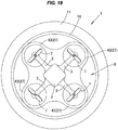
- the drone 9 is structured, more specifically as shown in Figs. 1 to 2 , such that four arms parts 3, 3, 3 and 3 are provided in a protruding manner in a radial pattern at an approximately 90 degree angle pitch in the horizontal plane, on an outer surface part 13 of the central mounting part 2 in which an inflator (not shown) for supplying the gas to the first airbag 11 and a trigger device (not shown) thereof are accommodated.
- Lengths of the arm parts 3 are set to be approximately the same length
- the rotary vane 7 which can rotate around the vertical axis 6 is provided in a front side position 5 of each of the arm parts 3, and the lift force is generated by the rotation of the rotary vane 7.
- a leg part 16 fixed its upper end to a base part 14 ( Fig. 1 ) of the arm part 3 is provided in a protruding manner so as to protrude out downward in a lower side of each of the arm parts 3.
- the first holding part 10 is formed into a circular ring shape existing in the horizontal plane as shown in Fig. 1 in the present embodiment, and is bent in a direction that upper and lower end parts 19 and 19 of a base plate part 17 formed into a circular ring shape face each other, and an accommodation part 20 is formed in an inner part thereof.
- the first airbag 11 in a small folded state is accommodated in the accommodation part 20 as shown in Fig. 3 , and a base part 21 thereof is fixed to a bottom part 22 of the accommodation part 20.
- the first holding part 10 is set its vertical length L1 to about 15 to 30 mm, for example, about 30 mm, and is set its width L2 in a horizontal direction to about 10 to 15 mm, for example, about 10 mm.
- the circular ring-shaped first holding part 10 having the structure mentioned above is structured, as shown in Fig. 1 in the present embodiment, such that a center 23 thereof is approximately in conformity to a center 25 of the central mounting part 2, and an inner peripheral surface part 26 thereof is positioned somewhat in an outer side of the four rotary vanes 7, 7, 7 and 7.
- the first holding part 10 is arranged via a first support part 27 protruded from the central mounting part 2 as shown in Fig. 1 in the present embodiment, and is substantially provided in the central mounting part 2. Further, the first support part 27 is constructed as an arm-shaped support part 27a for supporting the first holding part 10, in the present embodiment.
- the arm-shaped support part 27a is provided in a protruding manner on the outer surface part 13 of the central mounting part 2 between the arm parts 3 and 3 which are adjacent in the horizontal plane, and a front end part (a front end in the present embodiment) 30 of each of the arm-shaped support parts 27a is connected to the inner peripheral surface part 26 of the first holding part 10.
- the connection can be achieved by using a known means such as welding, screw fixing and various engaging means. Accordingly, the first holding part 10 is substantially provided in the central mounting part 2 via the first support part 27 as mentioned above.
- the first airbag 11 is constructed by using a resin raw material which is soft and has a desired strength, such as polyurethane, vinyl chloride, and nylon, the first airbag 11 in a folded state is housed in the accommodation part 20 as mentioned above, and a base part 21 thereof is fixed to the bottom part 22 of the accommodation part 20.
- a resin raw material which is soft and has a desired strength, such as polyurethane, vinyl chloride, and nylon
- the gas flows from the inflator via an opening part (not shown) into the first airbag 11 in the folded state as mentioned above, and the first airbag 11 is rapidly inflated.
- a state in which the first airbag 11 is inflated is shown in Figs. 4 to 6 .
- the first airbag 11 inflated as mentioned above is structured, as shown in Fig. 6 , such that the first airbag 11 is inflated in such a manner as to protrude outward from a front end edge 28 of the first holding part 10 in a state in which the base part 21 of the first airbag 11 is kept being fixed to the bottom part 22 of the accommodation part 20.
- the first airbag 11 is adapted to be inflated so as to protrude outward, for example, at about 30 to 50 mm.
- An amount of protrusion is appropriately set according to a shape and a size of the drone in such a manner as to effectively prevent the danger that the drone 1 injures the person in the case that the drone 1 collides with the other things such as the person as mentioned later
- the first inflation control device is provided with a detecting means (not shown) which automatically detects the fact that the drone 9 during the flight becomes uncontrollable under the influence of a trouble in the air frame, the abnormal weather or the radio disturbance, and an actuating means (not shown) which actuates the inflator on the basis of a detection signal of the detecting means before the collision with the other things such as to the person.
- the detecting means automatically detects the fact, and actuates the inflator on the basis of the detection signal of the detecting means before the collision with the other things such as the person, and the gas supplied from the inflator inflates the first airbag 11 via a gas piping (not shown) as mentioned above.
- the drone 9 comes to a state in which the drone 9 is surrounded in the horizontal plane by the first airbag 11 in the inflated state shown in Figs. 4 to 7 while putting the central mounting part 2 at the center.
- the uncontrollable drone 9 tends to be crashed in a state in which the first airbag 11 is in an approximately horizontal state or an inclined state
- the first airbag 11 in the inflated state achieves a good buffer action even in the case that the crashed drone 9 collides with the other things such as the person. Therefore, it is possible to effectively prevent the danger that the drone 1 injures the person in the case that the drone 1 collides with the other things such as the person.
- the drone with airbag 1 shown in Figs. 7 to 8 is provided with a second airbag (one aspect of the airbag 8) 32 in addition to the first airbag 11, and is provided with a second inflation control device (one aspect of the inflation control device) which controls inflation of the second airbag 32.
- the second inflation control device is provided with a detecting means (not shown) which automatically detects the fact that the drone 9 during the flight becomes uncontrollable under the influence of the trouble in the air frame, the abnormal weather or the radio disturbance, and an actuating means (not shown) which actuates the inflator mentioned above on the basis of a detection signal of the detecting means before the collision with the other things such as the person, in the same manner as the embodiment mentioned above.
- a second holding part 33 is provided in such a manner as to surround the drone 9 in the vertical plane while putting the central mounting part 2 at the center, and the second airbag 32 which can be inflated so as to protrude outward by the supplied gas is attached to the second holding part 33 in a folded state as shown in Fig. 11 .
- the second holding part 33 is formed into a circular ring shape or an oval ring shape existing in the vertical plane, and is arranged between the adjacent arm parts 3 and 3 in the present embodiment as shown in Figs. 9 to 10 .[
- the second holding part 33 is formed into an oval ring shape which is long in a horizontal direction and is comparatively short in a vertical direction, as seen in a vertical plane including an axis F of the arm-shaped support parts 27a and 27a which are arranged linearly between the arm parts 3 and 3, as shown in Figs. 9 to 10 .
- the central mounting part 2 is adapted to be received in an inner side of the oval ring-shaped second holding part 33.
- a lower end of the leg part 16 is made somewhat protrude downward in the second holding part 33 in such a manner that a lower end 34 of the leg part 16 in the drone 9 can ground on a ground plane 44 in a front view shown in Fig. 10 .
- the second holding part 33 is arranged via a second support part 40 which is provided in a protruding manner on the outer surface part 13 of the central mounting part 2, as shown in Fig. 10 .
- the second support part 40 is constructed as an arm-shaped support part 40a which is provided in a protruding manner vertically in the outer surface part 13 in the central mounting part 2, and a front end part (a front end in the present embodiment) 41 of each of the arm-shaped support parts 40a is connected to an inner peripheral surface part of the second holding part 33.
- the second holding part 33 is substantially provided in the central mounting part 2 via the second support part 40.
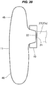
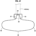
- the second holding part 33 is bent in a direction that right and left end parts 36 and 36 of a base plate part 35 formed into an oval ring shape face each other, as seen in a surface which is orthogonal to the vertical plane, and an accommodation part 37 is formed in an inner part thereof, as shown in Fig. 11 . Further, the second airbag 32 in the small folded state is accommodated in the accommodation part 37 as shown in Fig. 11 , and the base part 34 thereof is fixed to a bottom part 39 of the accommodation part 37.
- the second holding part 33 is set its lateral width L3 to about 15 to 30 mm, for example, about 20 mm, and set its width L3 in an internal direction thereof (a direction toward the central mounting part 2) to about 10 to 15 mm, for example, about 10 mm, in Fig. 11 .
- the second holding part 33 formed into the oval ring shape according to the structure mentioned above is substantially provided in the central mounting part 2.
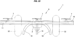
- the second airbag 32 held in the folded state by the second holding part 33 having the structure mentioned above can be inflated by the gas supplied on the basis of the control according to the second inflation control device (one aspect of the inflation control device). Further, the inflation is carried out before the drone 9 collides with the other things such as the person according to the control. Further, as shown in Figs. 12 and 7 to 8 , the inflated second airbag 32 is adapted to surround the drone 9 in the vertical plane while putting the central mounting part 2 at the center.
- the second airbag 32 is constructed by using the resin raw material which is soft and has the desired strength such as the polyurethane, the vinyl chloride or the nylon, in the same manner as that in the first airbag 11, the second airbag 32 in the folded state is accommodated in the accommodation part 37 ( Fig. 11 ), and the base part 34 thereof is fixed to the bottom part 39 of the accommodation part 37.
- the resin raw material which is soft and has the desired strength such as the polyurethane, the vinyl chloride or the nylon
- the gas flows from the inflator (not shown) into the second airbag 32 in the folded state as mentioned above through an opening part (not shown), and the second airbag 32 is adapted to be rapidly inflated.
- the state in which the second airbag 32 is inflated is shown in Figs. 7 , 8 and 12 , and the second airbag 32 is inflated in such a manner as to protrude outward from the second support part 40.
- the second airbag 32 is adapted to be inflated in such a manner as to protrude outward, for example, about 30 to 50 mm.
- An amount of protrusion is appropriately set according to the shape and the size of the drone, in such a manner as to effectively prevent the danger that the drone 1 injures the person in the case that the drone 1 collides with the other things such as the person, as mentioned later.
- the second inflation control device is provided with a detecting means (not shown) which automatically detects the fact that the drone 9 during the flight becomes uncontrollable under the influence of the trouble in the air frame, the abnormal weather or the radio disturbance, and the actuating means (not shown) which actuates the same inflator as mentioned above on the basis of the detection signal of the detecting means before the collision with the other things such as to the person.
- the detecting means of the first inflation control device and the detecting means of the second inflation control device automatically detect the fact, and actuate the inflator on the basis of the detection signals of the detecting means before the collision with the other things such as the person, and the gas supplied from the inflator inflates the first airbag 11 and the second airbag 32 via the gas piping (not shown) as mentioned above.
- the drone 9 comes to a state in which the drone 9 is surrounded in the horizontal plane by the first airbag 11 in the inflated state shown in Figs. 4 to 6 while putting the central mounting part 2 at the center. Further, the drone 9 comes to a state in which the drone 9 is surrounded in the vertical plane by the second airbag 32 in the inflated state while putting the central mounting part 2 at the center, as shown in Figs. 7 to 8 and 12 .
- the first airbag 11 and the second airbag 32 in the inflated state achieve a good buffer action.
- the buffer action can be achieved in the horizontal direction and the vertical direction. Therefore, it is possible to more effectively prevent the danger that the drone 9 collides with the person and injures the person.
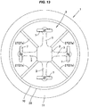
- the drone with airbag 1 shown in Fig. 13 is structured such that the first airbag 11 having the same structure as mentioned above is attached to the first holding part 10 in the drone with airbag 1 shown in the embodiment 1, and the first airbag 11 is in an inflated state from the beginning by the supplied gas.
- the first airbag 11 is provided in such a manner as to surround the drone 9 in the horizontal plane (for example, in such a manner as to surround in the horizontal plane while putting the central mounting part at the center) in the same manner as mentioned above.
Landscapes
- Engineering & Computer Science (AREA)
- Aviation & Aerospace Engineering (AREA)
- Mechanical Engineering (AREA)
- Remote Sensing (AREA)
- Business, Economics & Management (AREA)
- Emergency Management (AREA)
- Air Bags (AREA)
- Toys (AREA)
Applications Claiming Priority (3)
| Application Number | Priority Date | Filing Date | Title |
|---|---|---|---|
| JP2016216367 | 2016-11-04 | ||
| JP2017073725A JP6217054B1 (ja) | 2016-11-04 | 2017-04-03 | エアバッグ付きドローン |
| PCT/JP2017/039219 WO2018084125A1 (fr) | 2016-11-04 | 2017-10-31 | Drone doté d'un coussin de sécurité gonflable |
Publications (3)
| Publication Number | Publication Date |
|---|---|
| EP3536612A1 true EP3536612A1 (fr) | 2019-09-11 |
| EP3536612A4 EP3536612A4 (fr) | 2020-06-24 |
| EP3536612B1 EP3536612B1 (fr) | 2025-08-06 |
Family
ID=60156742
Family Applications (1)
| Application Number | Title | Priority Date | Filing Date |
|---|---|---|---|
| EP17868210.0A Active EP3536612B1 (fr) | 2016-11-04 | 2017-10-31 | Drone doté d'un coussin de sécurité gonflable |
Country Status (6)
| Country | Link |
|---|---|
| US (1) | US11772597B2 (fr) |
| EP (1) | EP3536612B1 (fr) |
| JP (1) | JP6217054B1 (fr) |
| CN (2) | CN109715496A (fr) |
| TW (1) | TWI686328B (fr) |
| WO (1) | WO2018084125A1 (fr) |
Families Citing this family (29)
| Publication number | Priority date | Publication date | Assignee | Title |
|---|---|---|---|---|
| JP6217054B1 (ja) * | 2016-11-04 | 2017-10-25 | 株式会社松屋アールアンドディ | エアバッグ付きドローン |
| US20230012473A1 (en) * | 2016-12-20 | 2023-01-19 | Nippon Kayaku Kabushiki Kaisha | Airbag device for aircraft |
| CN107933944A (zh) * | 2018-01-17 | 2018-04-20 | 安徽翼讯飞行安全技术有限公司 | 一种仪器仪表的保护装置 |
| JP6385604B1 (ja) * | 2018-01-22 | 2018-09-05 | 株式会社松屋アールアンドディ | エアバッグ付きドローンの制御方法及びエアバッグ付きドローン |
| CN108622426B (zh) * | 2018-04-26 | 2019-11-08 | 合肥职业技术学院 | 一种无人机撞击保护设备 |
| EP3802317B1 (fr) * | 2018-06-05 | 2024-01-31 | Flirtey Holdings, Inc. | Système de sécurité passif |
| JP7226629B2 (ja) * | 2018-06-08 | 2023-02-21 | カシオ計算機株式会社 | 飛行装置、飛行方法及びプログラム |
| JP7102958B2 (ja) * | 2018-06-08 | 2022-07-20 | カシオ計算機株式会社 | 飛行装置、飛行方法及びプログラム |
| CN109050949A (zh) * | 2018-06-29 | 2018-12-21 | 河南聚合科技有限公司 | 一种可漂浮100米空中的无人值守边防警戒云平台 |
| WO2020026448A1 (fr) * | 2018-08-03 | 2020-02-06 | 楽天株式会社 | Élément de protection pour objet volant |
| JP7022341B2 (ja) * | 2018-08-20 | 2022-02-18 | 豊田合成株式会社 | ドローン用エアバッグ |
| CN110155351B (zh) * | 2019-04-24 | 2020-10-09 | 台州学院 | 一种带气囊的无人机 |
| JP6761150B1 (ja) * | 2019-07-29 | 2020-09-23 | 楽天株式会社 | 無人飛行装置 |
| CN110834735A (zh) * | 2019-10-31 | 2020-02-25 | 绍兴文理学院元培学院 | 一种无人机坠落保护装置 |
| CN111038718A (zh) * | 2020-01-07 | 2020-04-21 | 中铁第五勘察设计院集团有限公司 | 一种无人机 |
| JP7276197B2 (ja) * | 2020-02-28 | 2023-05-18 | 豊田合成株式会社 | ドローン用保護装置 |
| JP7287363B2 (ja) * | 2020-08-13 | 2023-06-06 | Jfeスチール株式会社 | ドローン拘束状態離脱装置、ドローンおよびドローン拘束状態離脱方法 |
| CN112061408B (zh) * | 2020-09-17 | 2022-05-24 | 广州鼎奥科技有限公司 | 一种带有气囊保护装置的无人机 |
| CN112373681A (zh) * | 2020-11-20 | 2021-02-19 | 河南城建学院 | 一种航空遥感测绘无人机减震装置 |
| US12012208B2 (en) * | 2020-12-23 | 2024-06-18 | Osmose Utilities Services, Inc. | Systems and methods for inspecting structures with an unmanned aerial vehicle |
| CN113060294B (zh) * | 2021-04-07 | 2025-06-06 | 同济大学 | 一种多功能气囊旋翼无人机系统及控制方法 |
| CN113044226B (zh) * | 2021-05-10 | 2022-05-13 | 陕西星汉智维科技有限公司 | 一种可用于丛林拍摄的无人机 |
| CN114379800A (zh) * | 2021-12-31 | 2022-04-22 | 池州学院 | 一种无人机飞行防撞装置 |
| US11794882B1 (en) | 2022-08-14 | 2023-10-24 | SURVICE Engineering Company LLC | Shock absorption system for an unmanned aerial vehicle |
| CN115675931B (zh) * | 2022-10-25 | 2025-07-22 | 上海宇航系统工程研究所 | 一种可重复使用气囊缓冲着陆机构及深空探测器 |
| CN116552844B (zh) * | 2023-05-26 | 2025-06-27 | 浙江经纬测绘有限公司 | 一种无人机 |
| CN116714800B (zh) * | 2023-07-01 | 2025-10-10 | 台州学院 | 一种旋翼无人机的水平气囊保护装置及保护方法 |
| CN119453167A (zh) * | 2024-12-06 | 2025-02-18 | 山西省关帝山国有林管理局白虎岭林场 | 林业病虫害治理用农药喷洒装置 |
| CN119975850A (zh) * | 2025-04-14 | 2025-05-13 | 北京凌空天行科技有限责任公司 | 一种用于航天飞行器回收的浮力气囊组件、回收系统和航天飞行器 |
Family Cites Families (34)
| Publication number | Priority date | Publication date | Assignee | Title |
|---|---|---|---|---|
| JPS5857326B2 (ja) | 1979-02-19 | 1983-12-20 | 善一 今川 | レツカ−車 |
| US7201346B2 (en) * | 2003-04-25 | 2007-04-10 | Brad C Hansen | Circular fixed wing VTOL aircraft |
| KR101260370B1 (ko) * | 2011-01-20 | 2013-05-07 | 건국대학교 산학협력단 | 회전익 비행체 로봇 보호용 복합 구조 |
| US20130233964A1 (en) * | 2012-03-07 | 2013-09-12 | Aurora Flight Sciences Corporation | Tethered aerial system for data gathering |
| CN202802770U (zh) * | 2012-09-05 | 2013-03-20 | 汕头市博迪科技有限公司 | 多轴飞行器玩具 |
| CN203060835U (zh) * | 2013-01-19 | 2013-07-17 | 汕头市亨迪实业有限公司 | 一种抗撞能力强的遥控飞行玩具 |
| CN203227299U (zh) * | 2013-05-20 | 2013-10-09 | 汕头市亨迪实业有限公司 | 一种可贴壁飞行的遥控飞行玩具 |
| CN110626510A (zh) * | 2014-02-27 | 2019-12-31 | 深圳市大疆创新科技有限公司 | 撞击保护设备 |
| US20160272333A1 (en) | 2014-03-31 | 2016-09-22 | Sharper Shape Oy | Autonomous airbag system for unmanned aerial vehicles |
| US9613539B1 (en) * | 2014-08-19 | 2017-04-04 | Amazon Technologies, Inc. | Damage avoidance system for unmanned aerial vehicle |
| US20160114958A1 (en) * | 2014-10-24 | 2016-04-28 | David A. Busche | Chemotaxis Antibacterial Film and Package |
| EP3034407B1 (fr) * | 2014-12-16 | 2017-09-06 | Airbus (S.A.S.) | Système de protection à airbag |
| JP2016165987A (ja) * | 2015-03-09 | 2016-09-15 | 幸明 十田 | 無人マルチローター型ヘリコプターの機体ガード装置 |
| KR101558178B1 (ko) * | 2015-04-06 | 2015-10-08 | (주)하이레벤 | 에어백 시스템을 구비한 무인 항공기 촬영 시스템 |
| CN106458324B (zh) | 2015-04-18 | 2020-12-15 | Adtex公司 | 无人飞行物体及其控制装置 |
| US20160332739A1 (en) * | 2015-05-15 | 2016-11-17 | Disney Enterprises, Inc. | Impact absorption apparatus for unmanned aerial vehicle |
| CN104943872A (zh) * | 2015-06-10 | 2015-09-30 | 刘亚敏 | 一种无人驾驶飞行器及其保护方法 |
| JP5875093B1 (ja) | 2015-06-17 | 2016-03-02 | 浩平 中村 | 浮揚型飛行体 |
| US9611045B2 (en) | 2015-06-19 | 2017-04-04 | Indemnis, Inc. | Inflatable parachute airbag system |
| JP6169671B2 (ja) * | 2015-11-26 | 2017-07-26 | 株式会社オプティム | 無人航空機、無人航空機制御方法、及び無人航空機制御プログラム |
| CN105292505B (zh) * | 2015-12-03 | 2017-11-21 | 天津经天航空科技有限公司 | 一种多旋翼无人机着陆保护装置 |
| KR101630207B1 (ko) * | 2015-12-30 | 2016-06-24 | 장석훈 | 무인 비행체 회수 장치 및 그 방법 |
| CN205499330U (zh) * | 2016-02-04 | 2016-08-24 | 普宙飞行器科技(深圳)有限公司 | 一种具有自救气囊的无人机 |
| CN205396561U (zh) * | 2016-03-04 | 2016-07-27 | 广州市海葱科技有限公司 | 一种有防撞气囊的飞行器 |
| WO2018009254A2 (fr) * | 2016-03-24 | 2018-01-11 | Rhombus Systems Group, Inc. | Système d'airbag destiné à être utilisé avec des aéronefs sans pilote |
| JP6813997B2 (ja) * | 2016-09-02 | 2021-01-13 | 株式会社ダイセル | エアバッグ装置を備えた小型飛行体 |
| JP6217054B1 (ja) * | 2016-11-04 | 2017-10-25 | 株式会社松屋アールアンドディ | エアバッグ付きドローン |
| JP7034091B2 (ja) * | 2016-12-20 | 2022-03-11 | 日本化薬株式会社 | 飛行体用のエアバッグ装置 |
| JP7086083B2 (ja) * | 2017-08-24 | 2022-06-17 | 日本化薬株式会社 | 飛行体用安全装置および飛行体 |
| JP6905445B2 (ja) * | 2017-10-16 | 2021-07-21 | 日本化薬株式会社 | 墜落検知装置、飛行体の墜落を検知する方法、パラシュートまたはパラグライダーの展開装置、およびエアバッグ装置 |
| US11046443B2 (en) * | 2017-11-07 | 2021-06-29 | Intel Corporation | Safety systems for unmanned vehicles |
| CN111344227A (zh) * | 2017-11-10 | 2020-06-26 | 日本化药株式会社 | 飞行体用安全装置以及飞行体 |
| JP6385604B1 (ja) * | 2018-01-22 | 2018-09-05 | 株式会社松屋アールアンドディ | エアバッグ付きドローンの制御方法及びエアバッグ付きドローン |
| USD867207S1 (en) * | 2018-02-16 | 2019-11-19 | Spin Master Ltd. | Drone |
-
2017
- 2017-04-03 JP JP2017073725A patent/JP6217054B1/ja active Active
- 2017-10-31 CN CN201780057843.7A patent/CN109715496A/zh active Pending
- 2017-10-31 WO PCT/JP2017/039219 patent/WO2018084125A1/fr not_active Ceased
- 2017-10-31 CN CN202211286285.0A patent/CN115535274A/zh active Pending
- 2017-10-31 EP EP17868210.0A patent/EP3536612B1/fr active Active
- 2017-10-31 US US16/339,816 patent/US11772597B2/en active Active
- 2017-11-03 TW TW106138158A patent/TWI686328B/zh active
Also Published As
| Publication number | Publication date |
|---|---|
| CN109715496A (zh) | 2019-05-03 |
| JP6217054B1 (ja) | 2017-10-25 |
| US11772597B2 (en) | 2023-10-03 |
| JP2018079911A (ja) | 2018-05-24 |
| CN115535274A (zh) | 2022-12-30 |
| WO2018084125A1 (fr) | 2018-05-11 |
| US20200039466A1 (en) | 2020-02-06 |
| TW201823107A (zh) | 2018-07-01 |
| EP3536612A4 (fr) | 2020-06-24 |
| TWI686328B (zh) | 2020-03-01 |
| EP3536612B1 (fr) | 2025-08-06 |
Similar Documents
| Publication | Publication Date | Title |
|---|---|---|
| US11772597B2 (en) | Drone with airbag | |
| EP3744639A1 (fr) | Procédé de commande pour drone doté d'un coussin de sécurité gonflable, et drone doté d'un coussin de sécurité gonflable | |
| EP2960116B1 (fr) | Dispositif d'airbag latéral d'extrémité | |
| EP2960117B1 (fr) | Dispositif d'airbag lateral | |
| KR20150128051A (ko) | 에어백 모듈 | |
| KR20160045489A (ko) | 차량의 커튼 에어백 | |
| US6561538B2 (en) | Annular air bag and driver side air bag module | |
| WO2019069796A1 (fr) | Dispositif de coussin de sécurité gonflable | |
| EP3300957A1 (fr) | Coussin de sécurité gonflable avec lien de retenue | |
| JP2006500268A (ja) | エアバッグ | |
| JP2008137638A (ja) | 側突用エアバッグ、側突用エアバッグ装置、車両用シート | |
| KR101867065B1 (ko) | 자동차의 운전석 에어백 장치 | |
| JP4836494B2 (ja) | エアバッグ装置 | |
| KR20150130843A (ko) | 차량의 에어백 | |
| JP2005119510A (ja) | サイドエアバッグ装置 | |
| JP2009023437A (ja) | エアバッグ装置 | |
| US8474866B1 (en) | Airbag with zones of less elastic material | |
| JPH10287195A (ja) | 側突用エアバッグ | |
| JP2005247188A (ja) | エアバッグ装置 | |
| JPH09263206A (ja) | エアバッグ装置のエアバッグ | |
| JP5044439B2 (ja) | エアバック装置 | |
| KR101685491B1 (ko) | 차량용 테더클립 | |
| KR20090048916A (ko) | 조수석 에어백 도어 구조 | |
| JP2012148638A (ja) | カーテンエアバッグ装置 | |
| KR20210000906A (ko) | 루프 에어백 장치 |
Legal Events
| Date | Code | Title | Description |
|---|---|---|---|
| STAA | Information on the status of an ep patent application or granted ep patent |
Free format text: STATUS: THE INTERNATIONAL PUBLICATION HAS BEEN MADE |
|
| PUAI | Public reference made under article 153(3) epc to a published international application that has entered the european phase |
Free format text: ORIGINAL CODE: 0009012 |
|
| STAA | Information on the status of an ep patent application or granted ep patent |
Free format text: STATUS: REQUEST FOR EXAMINATION WAS MADE |
|
| 17P | Request for examination filed |
Effective date: 20190320 |
|
| AK | Designated contracting states |
Kind code of ref document: A1 Designated state(s): AL AT BE BG CH CY CZ DE DK EE ES FI FR GB GR HR HU IE IS IT LI LT LU LV MC MK MT NL NO PL PT RO RS SE SI SK SM TR |
|
| AX | Request for extension of the european patent |
Extension state: BA ME |
|
| DAV | Request for validation of the european patent (deleted) | ||
| DAX | Request for extension of the european patent (deleted) | ||
| A4 | Supplementary search report drawn up and despatched |
Effective date: 20200526 |
|
| RIC1 | Information provided on ipc code assigned before grant |
Ipc: B64D 25/00 20060101ALI20200518BHEP Ipc: B64C 27/08 20060101ALI20200518BHEP Ipc: B64D 45/00 20060101ALI20200518BHEP Ipc: B64C 39/02 20060101AFI20200518BHEP |
|
| RAP1 | Party data changed (applicant data changed or rights of an application transferred) |
Owner name: MATSUYA R&D CO., LTD |
|
| STAA | Information on the status of an ep patent application or granted ep patent |
Free format text: STATUS: EXAMINATION IS IN PROGRESS |
|
| 17Q | First examination report despatched |
Effective date: 20210316 |
|
| GRAP | Despatch of communication of intention to grant a patent |
Free format text: ORIGINAL CODE: EPIDOSNIGR1 |
|
| GRAJ | Information related to disapproval of communication of intention to grant by the applicant or resumption of examination proceedings by the epo deleted |
Free format text: ORIGINAL CODE: EPIDOSDIGR1 |
|
| GRAP | Despatch of communication of intention to grant a patent |
Free format text: ORIGINAL CODE: EPIDOSNIGR1 |
|
| STAA | Information on the status of an ep patent application or granted ep patent |
Free format text: STATUS: GRANT OF PATENT IS INTENDED |
|
| INTG | Intention to grant announced |
Effective date: 20250317 |
|
| GRAS | Grant fee paid |
Free format text: ORIGINAL CODE: EPIDOSNIGR3 |
|
| GRAA | (expected) grant |
Free format text: ORIGINAL CODE: 0009210 |
|
| STAA | Information on the status of an ep patent application or granted ep patent |
Free format text: STATUS: THE PATENT HAS BEEN GRANTED |
|
| P01 | Opt-out of the competence of the unified patent court (upc) registered |
Free format text: CASE NUMBER: APP_28098/2025 Effective date: 20250612 |
|
| AK | Designated contracting states |
Kind code of ref document: B1 Designated state(s): AL AT BE BG CH CY CZ DE DK EE ES FI FR GB GR HR HU IE IS IT LI LT LU LV MC MK MT NL NO PL PT RO RS SE SI SK SM TR |
|
| REG | Reference to a national code |
Ref country code: GB Ref legal event code: FG4D |
|
| REG | Reference to a national code |
Ref country code: CH Ref legal event code: EP |
|
| REG | Reference to a national code |
Ref country code: IE Ref legal event code: FG4D |
|
| REG | Reference to a national code |
Ref country code: DE Ref legal event code: R096 Ref document number: 602017091082 Country of ref document: DE |
|
| REG | Reference to a national code |
Ref country code: NL Ref legal event code: MP Effective date: 20250806 |
|
| PG25 | Lapsed in a contracting state [announced via postgrant information from national office to epo] |
Ref country code: IS Free format text: LAPSE BECAUSE OF FAILURE TO SUBMIT A TRANSLATION OF THE DESCRIPTION OR TO PAY THE FEE WITHIN THE PRESCRIBED TIME-LIMIT Effective date: 20251206 |
|
| PGFP | Annual fee paid to national office [announced via postgrant information from national office to epo] |
Ref country code: DE Payment date: 20251029 Year of fee payment: 9 |
|
| PG25 | Lapsed in a contracting state [announced via postgrant information from national office to epo] |
Ref country code: NO Free format text: LAPSE BECAUSE OF FAILURE TO SUBMIT A TRANSLATION OF THE DESCRIPTION OR TO PAY THE FEE WITHIN THE PRESCRIBED TIME-LIMIT Effective date: 20251106 |
|
| REG | Reference to a national code |
Ref country code: LT Ref legal event code: MG9D |
|
| PG25 | Lapsed in a contracting state [announced via postgrant information from national office to epo] |
Ref country code: PT Free format text: LAPSE BECAUSE OF FAILURE TO SUBMIT A TRANSLATION OF THE DESCRIPTION OR TO PAY THE FEE WITHIN THE PRESCRIBED TIME-LIMIT Effective date: 20251209 |
|
| PG25 | Lapsed in a contracting state [announced via postgrant information from national office to epo] |
Ref country code: FI Free format text: LAPSE BECAUSE OF FAILURE TO SUBMIT A TRANSLATION OF THE DESCRIPTION OR TO PAY THE FEE WITHIN THE PRESCRIBED TIME-LIMIT Effective date: 20250806 |
|
| PG25 | Lapsed in a contracting state [announced via postgrant information from national office to epo] |
Ref country code: NL Free format text: LAPSE BECAUSE OF FAILURE TO SUBMIT A TRANSLATION OF THE DESCRIPTION OR TO PAY THE FEE WITHIN THE PRESCRIBED TIME-LIMIT Effective date: 20250806 Ref country code: HR Free format text: LAPSE BECAUSE OF FAILURE TO SUBMIT A TRANSLATION OF THE DESCRIPTION OR TO PAY THE FEE WITHIN THE PRESCRIBED TIME-LIMIT Effective date: 20250806 |
|
| PGFP | Annual fee paid to national office [announced via postgrant information from national office to epo] |
Ref country code: FR Payment date: 20251024 Year of fee payment: 9 |
|
| PG25 | Lapsed in a contracting state [announced via postgrant information from national office to epo] |
Ref country code: GR Free format text: LAPSE BECAUSE OF FAILURE TO SUBMIT A TRANSLATION OF THE DESCRIPTION OR TO PAY THE FEE WITHIN THE PRESCRIBED TIME-LIMIT Effective date: 20251107 |
|
| PG25 | Lapsed in a contracting state [announced via postgrant information from national office to epo] |
Ref country code: SE Free format text: LAPSE BECAUSE OF FAILURE TO SUBMIT A TRANSLATION OF THE DESCRIPTION OR TO PAY THE FEE WITHIN THE PRESCRIBED TIME-LIMIT Effective date: 20250806 |
|
| PG25 | Lapsed in a contracting state [announced via postgrant information from national office to epo] |
Ref country code: LV Free format text: LAPSE BECAUSE OF FAILURE TO SUBMIT A TRANSLATION OF THE DESCRIPTION OR TO PAY THE FEE WITHIN THE PRESCRIBED TIME-LIMIT Effective date: 20250806 |
|
| PG25 | Lapsed in a contracting state [announced via postgrant information from national office to epo] |
Ref country code: BG Free format text: LAPSE BECAUSE OF FAILURE TO SUBMIT A TRANSLATION OF THE DESCRIPTION OR TO PAY THE FEE WITHIN THE PRESCRIBED TIME-LIMIT Effective date: 20250806 Ref country code: PL Free format text: LAPSE BECAUSE OF FAILURE TO SUBMIT A TRANSLATION OF THE DESCRIPTION OR TO PAY THE FEE WITHIN THE PRESCRIBED TIME-LIMIT Effective date: 20250806 |
|
| PG25 | Lapsed in a contracting state [announced via postgrant information from national office to epo] |
Ref country code: RS Free format text: LAPSE BECAUSE OF FAILURE TO SUBMIT A TRANSLATION OF THE DESCRIPTION OR TO PAY THE FEE WITHIN THE PRESCRIBED TIME-LIMIT Effective date: 20251106 |
|
| PG25 | Lapsed in a contracting state [announced via postgrant information from national office to epo] |
Ref country code: ES Free format text: LAPSE BECAUSE OF FAILURE TO SUBMIT A TRANSLATION OF THE DESCRIPTION OR TO PAY THE FEE WITHIN THE PRESCRIBED TIME-LIMIT Effective date: 20250806 |
|
| REG | Reference to a national code |
Ref country code: AT Ref legal event code: MK05 Ref document number: 1821582 Country of ref document: AT Kind code of ref document: T Effective date: 20250806 |
|
| PG25 | Lapsed in a contracting state [announced via postgrant information from national office to epo] |
Ref country code: RO Free format text: LAPSE BECAUSE OF FAILURE TO SUBMIT A TRANSLATION OF THE DESCRIPTION OR TO PAY THE FEE WITHIN THE PRESCRIBED TIME-LIMIT Effective date: 20250806 |
|
| PG25 | Lapsed in a contracting state [announced via postgrant information from national office to epo] |
Ref country code: SM Free format text: LAPSE BECAUSE OF FAILURE TO SUBMIT A TRANSLATION OF THE DESCRIPTION OR TO PAY THE FEE WITHIN THE PRESCRIBED TIME-LIMIT Effective date: 20250806 |
|
| PG25 | Lapsed in a contracting state [announced via postgrant information from national office to epo] |
Ref country code: DK Free format text: LAPSE BECAUSE OF FAILURE TO SUBMIT A TRANSLATION OF THE DESCRIPTION OR TO PAY THE FEE WITHIN THE PRESCRIBED TIME-LIMIT Effective date: 20250806 |
|
| PG25 | Lapsed in a contracting state [announced via postgrant information from national office to epo] |
Ref country code: AT Free format text: LAPSE BECAUSE OF FAILURE TO SUBMIT A TRANSLATION OF THE DESCRIPTION OR TO PAY THE FEE WITHIN THE PRESCRIBED TIME-LIMIT Effective date: 20250806 |
|
| PG25 | Lapsed in a contracting state [announced via postgrant information from national office to epo] |
Ref country code: IT Free format text: LAPSE BECAUSE OF FAILURE TO SUBMIT A TRANSLATION OF THE DESCRIPTION OR TO PAY THE FEE WITHIN THE PRESCRIBED TIME-LIMIT Effective date: 20250806 |
|
| PG25 | Lapsed in a contracting state [announced via postgrant information from national office to epo] |
Ref country code: CZ Free format text: LAPSE BECAUSE OF FAILURE TO SUBMIT A TRANSLATION OF THE DESCRIPTION OR TO PAY THE FEE WITHIN THE PRESCRIBED TIME-LIMIT Effective date: 20250806 |
|
| PG25 | Lapsed in a contracting state [announced via postgrant information from national office to epo] |
Ref country code: EE Free format text: LAPSE BECAUSE OF FAILURE TO SUBMIT A TRANSLATION OF THE DESCRIPTION OR TO PAY THE FEE WITHIN THE PRESCRIBED TIME-LIMIT Effective date: 20250806 Ref country code: SK Free format text: LAPSE BECAUSE OF FAILURE TO SUBMIT A TRANSLATION OF THE DESCRIPTION OR TO PAY THE FEE WITHIN THE PRESCRIBED TIME-LIMIT Effective date: 20250806 |