EP3536643B1 - Machine de bobinage sur tourelle à fixation électrostatique du début de bande - Google Patents
Machine de bobinage sur tourelle à fixation électrostatique du début de bande Download PDFInfo
- Publication number
- EP3536643B1 EP3536643B1 EP19157709.7A EP19157709A EP3536643B1 EP 3536643 B1 EP3536643 B1 EP 3536643B1 EP 19157709 A EP19157709 A EP 19157709A EP 3536643 B1 EP3536643 B1 EP 3536643B1
- Authority
- EP
- European Patent Office
- Prior art keywords
- winding
- web material
- winding core
- web
- turret
- Prior art date
- Legal status (The legal status is an assumption and is not a legal conclusion. Google has not performed a legal analysis and makes no representation as to the accuracy of the status listed.)
- Active
Links
Images
Classifications
-
- B—PERFORMING OPERATIONS; TRANSPORTING
- B65—CONVEYING; PACKING; STORING; HANDLING THIN OR FILAMENTARY MATERIAL
- B65H—HANDLING THIN OR FILAMENTARY MATERIAL, e.g. SHEETS, WEBS, CABLES
- B65H19/00—Changing the web roll
- B65H19/22—Changing the web roll in winding mechanisms or in connection with winding operations
- B65H19/28—Attaching the leading end of the web to the replacement web-roll core or spindle
-
- B—PERFORMING OPERATIONS; TRANSPORTING
- B65—CONVEYING; PACKING; STORING; HANDLING THIN OR FILAMENTARY MATERIAL
- B65H—HANDLING THIN OR FILAMENTARY MATERIAL, e.g. SHEETS, WEBS, CABLES
- B65H19/00—Changing the web roll
- B65H19/22—Changing the web roll in winding mechanisms or in connection with winding operations
- B65H19/2207—Changing the web roll in winding mechanisms or in connection with winding operations the web roll being driven by a winding mechanism of the centre or core drive type
- B65H19/2215—Turret-type with two roll supports
-
- B—PERFORMING OPERATIONS; TRANSPORTING
- B65—CONVEYING; PACKING; STORING; HANDLING THIN OR FILAMENTARY MATERIAL
- B65H—HANDLING THIN OR FILAMENTARY MATERIAL, e.g. SHEETS, WEBS, CABLES
- B65H2301/00—Handling processes for sheets or webs
- B65H2301/40—Type of handling process
- B65H2301/41—Winding, unwinding
- B65H2301/413—Supporting web roll
- B65H2301/4134—Both ends type arrangement
- B65H2301/41346—Both ends type arrangement separate elements engaging each end of the roll (e.g. chuck)
-
- B—PERFORMING OPERATIONS; TRANSPORTING
- B65—CONVEYING; PACKING; STORING; HANDLING THIN OR FILAMENTARY MATERIAL
- B65H—HANDLING THIN OR FILAMENTARY MATERIAL, e.g. SHEETS, WEBS, CABLES
- B65H2301/00—Handling processes for sheets or webs
- B65H2301/40—Type of handling process
- B65H2301/41—Winding, unwinding
- B65H2301/414—Winding
- B65H2301/41419—Starting winding process
- B65H2301/41421—Starting winding process involving electrostatic means
-
- B—PERFORMING OPERATIONS; TRANSPORTING
- B65—CONVEYING; PACKING; STORING; HANDLING THIN OR FILAMENTARY MATERIAL
- B65H—HANDLING THIN OR FILAMENTARY MATERIAL, e.g. SHEETS, WEBS, CABLES
- B65H2301/00—Handling processes for sheets or webs
- B65H2301/50—Auxiliary process performed during handling process
- B65H2301/51—Modifying a characteristic of handled material
- B65H2301/515—Cutting handled material
- B65H2301/5151—Cutting handled material transversally to feeding direction
-
- B—PERFORMING OPERATIONS; TRANSPORTING
- B65—CONVEYING; PACKING; STORING; HANDLING THIN OR FILAMENTARY MATERIAL
- B65H—HANDLING THIN OR FILAMENTARY MATERIAL, e.g. SHEETS, WEBS, CABLES
- B65H2404/00—Parts for transporting or guiding the handled material
- B65H2404/40—Shafts, cylinders, drums, spindles
- B65H2404/43—Rider roll construction
-
- B—PERFORMING OPERATIONS; TRANSPORTING
- B65—CONVEYING; PACKING; STORING; HANDLING THIN OR FILAMENTARY MATERIAL
- B65H—HANDLING THIN OR FILAMENTARY MATERIAL, e.g. SHEETS, WEBS, CABLES
- B65H2408/00—Specific machines
- B65H2408/20—Specific machines for handling web(s)
- B65H2408/23—Winding machines
- B65H2408/231—Turret winders
- B65H2408/2315—Turret winders specified by number of arms
- B65H2408/23152—Turret winders specified by number of arms with two arms
Definitions
- the invention relates to a turret winding machine for winding up an essentially insulating web material with electrostatic fixing of the beginning of the web on a winding core.
- Web materials are wound up into a roll, in particular directly after they have been produced, broken down into narrower webs, printed or further processed into bags, sacks or other packaging materials.
- Spiral winding machines in particular are used for this. These have a rotatable winding core carrier on which several winding cores are rotatably mounted. By rotating the winding core carrier, the winding cores are shifted one after the other into a winding-on position for winding on a beginning of the web and into a winding-up position for further winding up of the web material.
- the web material When the roll is fully wound in the winding position, the web material is severed by means of a cutting blade between the winding-on position and the winding-up position, and the following beginning of the web is wound onto the winding core in the winding-on position.
- the fully wound roll is removed from the winding core support and replaced with an unwound winding core.
- the winding core support is rotated until the winding core that has just been wound has reached the winding position and the still unwound winding core has reached the initial winding position, and the process begins again.
- sleeves eg made of metal or cardboard
- special adhesive tapes are used as winding cores, which fix the beginning of the web on the circumference of the sleeves. Gluing the beginning of the web limits the process speed, is expensive because of the adhesive tapes and is problematic for web materials for food.
- adhesive-free initial winding refers to the fixing of the beginning of the web on a winding core during initial winding by means of electrostatic charging.
- the web material When processing a web material that is essentially insulating, the web material can become highly electrostatically charged, in particular as a result of movement, deflection, friction, stretching and the use of electrostatic printing aids (ESA).
- ESA electrostatic printing aids
- the charges are stored in the material wound into a roll in a manner similar to that in a wound capacitor.
- voltage flashovers can occur during further processing of the web material, which endangers workers. Therefore, devices for unloading the continuous web material are known.
- the EP 3 222 421 A1 proposes a take-up device with a device for transferring electrical charges to the web material on the take-up roll and/or during deflection onto the take-up roll, which is connected to at least one electrical high-voltage source of positive or negative polarity, to compensate for unwanted charges. Also EP 0 183 135 A1 proposes a turret winder with a device for transferring electrical charges to fix the beginning of the web to the take-up roll.
- the invention is based on the object of creating a turret winding machine for winding up an essentially insulating web material with electrostatic fixation of the beginning of the web with more favorable manufacturing and operating properties.
- the turret winding machine with the same device for transferring electrical charges to the start of the web, charge is applied to fix it on the winding core in the initial winding position, and during further winding onto the same winding core, the charge required to compensate for charging during the production or processing of the web material is applied to the web material .
- This is done by arranging the means of transmission electrical charges between the pressure roller, which can be displaced towards the winding core in the initial winding position, and the displacement path of the cutting blade when the web material is cut open.
- both undesired charge of the web material before winding onto the winding core in the winding position can be compensated and after the web material has been severed, the following beginning of the web can be provided with a suitable charge for fixing on the winding core in the winding position.
- the charging of the beginning of the web before fixing can be controlled in such a way that, despite the web material being charged during its production or further processing, adequate fixing on the winding core is achieved. Due to the fact that the device for transferring electrical charges takes over both the fixing of the beginning of the web and the compensation of electrical charges on the web material, components are saved and the space required is reduced. As a result, the outlay for production and operation can be reduced.
- the high voltage electrical source supplies high electrical voltages of different polarity.
- the electric control device controls which of the electric high voltages with different polarity are applied to the electric charge transfer device. If the device for transferring electrical charges is designed as a needle electrode, a high voltage of different polarity can be applied to different rows of needles or a high voltage of a specific polarity can be applied to one row of needles and ground can be applied to another row of needles. In the case of a needle electrode with only a single row of needles, a high voltage of a certain polarity can be applied to this row of needles and the housing to ground. For loading the beginning of the web for fixing to the winding core a high voltage of the same polarity can be applied to one or two rows of needles of a needle electrode.
- the electrical high-voltage source supplies at least one adjustable high voltage to the device for transferring electrical charges onto the web material.
- the high voltage By adjusting the high voltage, it is possible to optimize the charge supplied to the web material to compensate for charging of the web material. Furthermore, the charge supplied to the start of the web for fixing the web material to the winding core can be optimized.
- the electrical control device is designed in such a way that it applies at least one electrical voltage to the device for transferring electrical charges with a level and/or polarity that causes the beginning of the web to be charged, which depends on the charging of the supplied web material.
- the level and/or polarity of the charge for fixing the beginning of the web on the winding core can be set depending on the level and/or polarity of the charge to compensate for the charging of the web material, e.g. according to a table based on empirical values.
- At least one field strength measuring device is arranged in such a way that it detects the web material fed to the turret winding machine, preferably when it is deflected onto the winding core or onto the winding core, with the field strength measuring device determining the charge that the web material has and being connected to the electrical control device , which is designed to apply a high voltage with a level and/or polarity to the device for transferring electrical charges that is determined by the charge of the web material measured by the field strength measuring device depends.
- the electrical control device can determine the high voltage required to compensate for the charging and/or the high voltage required to charge the beginning of the web for fixing it on the winding core, taking into account the measured charging.
- the electrical control device is designed in such a way that when the web material is being wound onto the winding core, it applies a high voltage to the device for transferring electrical charges with a level and/or polarity which causes minimal charging of the web material wound onto the winding core. This minimizes the risk of voltage flashovers.
- the means for imparting electrical charges to the sheet material is a charging electrode arranged so that the sheet material passes through the effective range of the charging electrode. Since the charging electrode can act on the web material from a distance, it is possible to position and/or relocate the charging electrode so that it does not collide with moving parts. In addition, by arranging the charging electrode at a distance from the web material, changes in the course of the web material can be bridged to a limited extent, for example due to the increase in the roll diameter when the web material is wound onto the winding core.
- the effective area of the charging electrode is defined as the area in which the field strength of the electric field generated by the charging electrode is at least 1% of the maximum field strength of this field, preferably at least 5%, preferably at least 10%, more preferably at least 20%. , preferably at least 50%.
- the charging electrode when the beginning of the web is fixed on the winding core, the charging electrode is arranged in such a way that its effective area covers the outer circumference of the winding core arranged in the winding station. This is particularly advantageous for fixing the beginning of the web on the winding core.
- the charging electrode is arranged on the same side of the web material as this pressure roller, next to the pressure roller that can be moved onto the winding core in the winding station.
- the charging electrode is directed with its effective area through the web material onto the outer circumference of the winding core in the winding station.
- the charging electrode is aligned with its effective area tangentially to the pressure roller that can be displaced on the winding core in the winding station. According to a further embodiment, the charging electrode is aligned radially to the winding core in the winding station when the web material is cut through.
- the charging electrode is a bar-shaped charging electrode.
- the charging electrode is a needle electrode.
- the charging electrode is preferably designed like a charging electrode that is used for the " top-loading " of impression rollers in electrostatic printing aids (ESA).
- ESA electrostatic printing aids
- the charging electrode is a bar-shaped needle electrode designed as shown in FIG EP 1 640 160 B1 described, in particular as the needle electrode according to 1 to 10 or 11 to 14 of this specification.
- the needle electrode has two parallel rows of needles.
- the same voltage can be applied to both rows of needles to charge the beginning of the web.
- the effective area is aligned axially in the direction of the needles.
- the effective area can be characterized by the course of the field lines. These are lines of constant field strength.
- the course of the field lines is elliptical, with the main axes of the ellipses being aligned in the direction of the needles and the secondary axes being perpendicular thereto.
- the cutting device is designed in such a way that the displacement path of the cutting knife when cutting the web material runs between the winding core in the initial winding position and the axis of rotation of the winding core support.
- the displacement path of the cutting blade preferably runs at a distance from the winding core in the winding-on position which is less than half the distance of this winding core from the axis of rotation of the winding core carrier.
- the web material is separated at a short distance from the winding core in the winding-on position, so that the beginning of the following web wraps around the winding core in the winding-on position.
- the wrapping and fixing is achieved by the electrical charging of the beginning of the web and, if necessary, the winding core.
- the device for transferring electrical charges and the pressure roller arranged next to the winding position are fixed to the same supporting structure. This is advantageous for positioning the device for transferring electrical charges, so that the start of the web is securely fixed on the winding core in the initial winding position.
- the support structure can be moved into and out of the area between the side parts by means of an infeed device. By shifting the support structure out of the area between the two side parts, it is possible to rotate the winding core carrier without colliding with the support structure and the components attached to it.
- the electrical control device is connected to the infeed device and is designed in such a way that the support structure with the pressure roller mounted on it is moved out of the area between the two side parts after the beginning of the web has been wound and after the winding core on which the web material is wound has been rotated is shifted from the winding-up position to the winding-up position in the position adjacent to the unwound winding core rotated into the winding-up position.
- the web material When the support structure is shifted out of the area between the two side parts, the web material continues to run over the pressure roller mounted thereon onto the winding core in the initial winding position. Here, the web material continues to be guided past the device for transferring electrical charges, which is attached to the support structure. This also compensates for charging of the web material when the supporting structure is shifted out of the area between the side parts. Even when the winding core carrier rotates the winding core from the initial winding position to the winding position, the web material is guided past the device for transferring electrical charges, so that the compensation of charges can be continued.
- the supporting structure with the pressure roller is shifted between the side parts next to the still unwound winding core in the winding-on position.
- the device for transferring electrical charges remains in the vicinity of the web material passing through, so that it can continue to compensate for charges on the same.
- a high voltage is transmitted to the device for transferring electrical charges in order to fix the beginning of the web on the winding core in the initial winding position.
- the turret winding machine comprises a blowing device which has at least one air outlet opening which is directed towards the web material between the pressure roller, which can be displaced towards the winding core in the initial winding position, and the displacement path of the cutting blade when the web material is cut open, and which is directed to a compressed air source connectable or connected.
- the blowing device supports the positioning and fixing of the beginning of the web on the winding core arranged in the initial winding position.
- the blowing device is bar-shaped with a compressed air duct which can be connected or connected to a compressed air source and has at least one air outlet opening, preferably at least one row of air outlet openings, on one side, with each air outlet opening being connected to the compressed air duct.
- the bar-shaped blowing device is aligned with the at least one air outlet hole on the web material and preferably perpendicular to the running direction of the web material.
- the blowing device is integrated into or attached to the device for transferring electrical charges.
- the device for transferring electrical charges with an integrated blowing device is a needle electrode with one or two rows of needles, which has a compressed air duct and a series of air outlet openings which are connected to the compressed air duct. This is a particularly space-saving design.
- the air outlet openings are arranged between two rows of needles.
- the compressed air channel is connected to a connecting piece for compressed air, which protrudes from one end of the needle electrode.
- the device for transferring electrical charges is a bar-shaped needle electrode with one or two rows of needles
- the blowing device is a bar-shaped blowing device which is attached to the side of the bar-shaped needle electrode and, as described above, has a compressed air duct and at least one air outlet opening connected to it.
- the blowing device is connected to a switchable valve (switching valve) which is connected or can be connected to the compressed air source.
- the blowing device can be connected to the compressed air source via the switchable valve when the web material is being cut open, in order to support the initial winding process. When winding up further, the blowing device can be separated from the compressed air source via the switchable valve.
- the switchable valve is connected to a compressed air duct of the blowing device, which in turn is connected to the at least one air outlet opening.
- the electrical control device is connected to the switchable valve and is designed to open the switchable valve when the web material is severed, so that compressed air can flow through the at least an air outlet opening of the blowing device exits, which moves the beginning of the web to the winding core in the initial winding position.
- the electrical control device simultaneously applies the electrical high voltage for fixing the beginning of the web to the device for transferring electrical charges and switches on the switchable valve which connects the blowing device to the compressed air source.
- the electrical control device is designed to close the switchable valve after the beginning of the web has been wound onto the winding core in the winding-on position.
- the electrical control device switches off the high voltage for fixing the beginning of the web and the blowing device at the same time.
- the cutting device is designed in such a way that the cutting blade, in the starting position before it runs through the path for severing the web material, is arranged on the same side of the web material as the device for transferring electrical charges. This makes it possible to bring the cutting device with the cutting blade to the web material from the same side as the device for transferring electrical charges. This is advantageous for a space-saving construction.
- the cutting device comprises a displacement device which is designed to displace the cutting blade in a direction that cuts the web material in order to sever the web material.
- the displacement device is designed to displace the cutting knife out of the area between the two side parts and into the area between the two side parts.
- the cutting knife If the cutting knife shifted out of the area between the side parts, it does not hinder the rotation of the winding core support. To cut through the web material, the cutting blade is moved into the area between the side parts.
- the displacement device is a separate device from the delivery device.
- the cutting blade has a cutting edge which extends over the entire width of the web material. As a result, the strip material is cut off in a straight line and wound up evenly on the winding core.
- the side parts of the winding core carrier are disks, in particular circular disks.
- the side parts each have support arms which protrude radially with respect to the axis of rotation and on which the holding devices are arranged. Free spaces are preferably present between the support arms.
- the side parts can be formed exclusively by the support arms.
- the electrical control device is designed in such a way that while the web material is being separated by means of the cutting device and/or a defined period of time before the web material is severed by means of the cutting device of the device for transferring electrical charge, it does not apply any high electrical voltage to compensate for charging of the web material feeds more and instead feeds an electrical high voltage to the device for transferring electrical charge in order to fix the beginning of the web on the winding core in the winding-on position. This ensures that charges are fed to the beginning of the web for fixing on the winding core in the initial winding position.
- charges for fixing the web material are fed in before the cutting knife cuts through, charges are also fed to the leading end of the web, the level of which, however, is so low that it does not cause any voltage flashovers from the roll that could endanger the worker.
- these charges can fix the end of the web on the finished roll.
- the period of time during which the corresponding charges are fed before the web material is separated can be determined as a function of the throughput speed, the charges required to fix the beginning of the web on the winding core in the winding position and the charges that can be fed to the end of the web without the risk of voltage flashovers endangering the work personnel become.
- the electrical control device is designed in such a way that it supplies the web material with the electrical high voltage for fixing the beginning of the web on the winding core in the initial winding position for a specific period of time.
- This period of time is preferably selected in such a way that it is sufficient for the web material to be securely fixed to the winding core and the charges fed to the roll in this way do not cause any voltage flashovers that could endanger the work personnel.
- the essentially insulating web materials are in particular plastic films or composite films containing a plastic or web materials made from plastic films or composite films.
- Composite films can contain the plastic, for example, in the form of a plastic film, an extruded layer or applied plastic films. In addition, they include, for example, a metal foil, a paper web, a cardboard web or another plastic film. In addition, the composite film can comprise a combination of any one or more of the aforementioned components.
- the web material can in particular be a printing material.
- the web material can in particular be a printing material printed in a printing machine. This can in particular be a packaging material.
- the turret winding machine is part of a rotary printing machine or a web-fed printing machine. According to a further embodiment, it is a gravure printing press, flexographic printing press, offset printing press, letterpress printing press, planographic printing press or screen printing press.
- the turret winding machine is part of a slitting machine.
- the turret winding machine is part of a film extrusion machine.
- the turret winding machine is part of a laminating machine.
- the turret winding machine according to the invention can be used in other areas of application in which web material made from essentially electrically insulating material is wound up into a roll.
- Embodiments of the turret winding machine are specified in the dependent claims and in the above description.
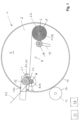
- a turret winding machine 1 has a winding core carrier 2 with two circular disc-shaped side parts 3, one of which is shown.
- the two side parts 3 are arranged at a distance from one another, parallel to one another and with their center on the same axis of rotation 4 .
- the side parts 3 On the sides facing one another, the side parts 3 have holding devices 5, 6 for the detachable holding and rotatable mounting of winding cores 7, 8.
- the holding devices 5, 6 are pins, for example with a cylindrical shape.
- the winding cores 7, 8 are sleeves, in the ends of which the pins 5, 6 can be inserted.
- the sleeves and the pins have a tongue and groove connection 9, 10, 11, 12.
- the holding devices 5, 6 are each coupled to a winding drive device in order to rotate the winding cores 7, 8 about winding axes which are parallel to the axis of rotation 4.
- the winding core carrier 2 is coupled to a drive device 13 in order to rotate the winding core carrier 2 about its axis of rotation 4 optionally with one holding device 5 into the winding position at the same time as the other holding devices 6 in the winding position and vice versa.
- the drive device 13 and the winding core carrier 2 have toothed rims 14, 15 on their circumferences, which mesh.
- a pressure roller 16 is arranged parallel to the winding core 7 next to the initial winding position.
- the pressure roller 16 is mounted on a support structure 17 in the form of a beam. In the winding-on position shown, there is a gap between the winding core 7 arranged in the winding-on position and the pressure roller 16 .
- the support structure 17 can be moved by means of an infeed device from the position shown at a distance from the winding core 7 to the winding core 7, so that it bears against the latter and rolls on it.
- the infeed device is designed in such a way that the support structure 17 with the pressure roller 16 can be pulled out of the area between the side parts 3 in order to enable the winding core carrier 2 to rotate.
- a further pressure roller 18 is arranged between the two side parts 3 next to the winding core 8 in the winding position.
- the additional pressure roller 18 can be advanced radially towards this winding core 8 by means of an infeed device 10 .
- This device for feeding 19 can in particular be a device which presses the further pressure roller 18 against the circumference of the winding core 8 under pretension.
- a web material 20 is guided on the winding core 7 side in the winding position over the circumference of the pressure roller 16 onto the winding core 8 in the winding position.
- the web material 20 When being wound onto the winding core 8 in the winding position, the web material 20 can be pressed against the winding core 8 by the additional pressure roller 18 .
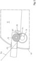
- a device for transferring electrical charges 21 is fixed at the end of the support structure 17, this being a bar-shaped charging electrode which is designed as a needle electrode.
- the area of action of the charging electrode 21 is characterized by elliptical field lines 22 .
- the charging electrode is aligned with its effective area in such a way that it touches the pressure roller 16 and hits the winding core 7 radially in the initial winding position.
- the charging electrode is electrically connected to a high-voltage electrical source 23 .
- a blowing device is integrated into the needle electrode 21 .
- This comprises a compressed air channel directed in the longitudinal direction of the needle electrode, a connecting piece for compressed air at one end of the needle electrode and a row of air outlet openings on the side of the needle electrode on which it has the needles from which the field lines emanate.
- a cutting knife 24 of a cutting device 25 is arranged further away from the winding station in the direction of passage of the web material 20 than the Device for transferring electrical charges 21. Charging electrode and cutting knife 24 are on the same side of the web material 20.
- the cutting device 25 comprises a displacement device which is designed to move the cutting knife 24 perpendicular to the web material 20 into the area between the initial winding position and the winding position in order to to cut through the web material 20.
- the electrical high-voltage supply 23, the drive device 13 for the winding core support 2, the winding drive devices, the infeed device for the pressure roller 16 and the charging electrode 21 and the displacement device of the cutting device 25 are connected to an electrical control device 26.
- the electrical control device 26 controls the drives so that the movable components change the position of 1 assume.
- the electrical high-voltage supply 23 controls it in such a way that the charging electrode 21 compensates for charging of the web material 20 as a result of a previous production and/or processing operation. This avoids that charges are stored in the roll 27 on the winding core 8 .
- the control device 26 controls the cutting device 25 so that the cutting knife 24 cuts through the web material 20 .
- the control device 26 controls the high-voltage supply 23 in such a way that the charging electrode 21 no longer compensates for the charging of the web material 20 .
- the applied high voltage generates an electrical field which causes the start of the web behind the cut on the winding core 7 in the initial winding position fixed.
- the pressure roller 16 can be pressed against the winding core 7 from the outside.
- control device 26 connects the blowing device to a high-pressure source via a switchable valve, so that the beginning of the web is additionally pressed against the winding core 7 by the compressed air emerging from the air outlet openings. As a result, the start of the web is wound onto the winding core 7 .
- the support structure 17 is moved out of the area between the side parts 3 by means of the infeed device. Furthermore, the cutting knife 24 is shifted out of the area between the two side parts 3 by means of the shifting device.
- the web material 20 continues to be guided over the pressure roller 16 onto the winding core 7 and wound up. Here, the web material 20 continues to run past the charging electrode 21 . As a result, charging of the web material 20 can continue to be compensated for by the charging electrode 21 .
- the winding core support 2 is rotated by the drive device 13 so that the unwound winding core 2 reaches the winding-on position and the partially wound winding core 7 moves into the winding-up position. During this process, further web material 20 is continuously wound onto the winding core 7 .
- the pressure roller 16 and the charging electrode 21 are moved back into the area between the side parts 3 by means of the infeed device and the cutting knife 24 by means of the displacement device. Then they take the in again figure 1 and 2 shown position next to the winding position, which is occupied by the unwound winding core 8.
Landscapes
- Replacement Of Web Rolls (AREA)
- Winding Of Webs (AREA)
- Manufacture Of Motors, Generators (AREA)
- Registering, Tensioning, Guiding Webs, And Rollers Therefor (AREA)
Claims (20)
- Machine de bobinage sur tourelle pour le bobinage d'un matériau en bande essentiellement isolant avec fixation électrostatique du début de bande sur un noyau de bobinage, comportant :un support de noyau de bobinage (2) monté de façon rotative autour d'un axe de rotation, avec deux parties latérales (3) disposées à distance l'une de l'autre et présentant respectivement des dispositifs de maintien (5, 6) sur les côtés tournés l'un vers l'autre à différentes positions circonférentielles pour le maintien détachable aux deux extrémités d'un noyau de bobinage (7, 8) et le montage rotatif de celui-ci autour d'un axe de bobinage parallèle à l'axe de rotation (4),un dispositif d'entraînement (13) accouplé au support de noyau de bobinage (2), pour le déplacement du support de noyau de bobinage (2) avec les premiers dispositifs de maintien (5) et le noyau de bobinage (7) maintenu par ceux-ci vers une position d'amorce de bobinage et simultanément avec les autres dispositifs de maintien (6) et le noyau de bobinage (8) maintenu par ceux-ci vers une position de bobinage,des cylindres de pression (16, 18) montés de façon rotative, parmi lesquels l'un est déplaçable entre les deux parties latérales (3) dans la direction radiale sur le noyau de bobinage (7) dans la position d'amorce de bobinage et l'autre est déplaçable entre les deux parties latérales (3) dans la direction radiale sur le noyau de bobinage (8) dans la position de bobinage,un dispositif de coupe (25) doté d'une lame de coupe (24) et d'un dispositif de déplacement permettant de déplacer la lame de coupe (24) entre les deux parties latérales (3) dans la région d'espacement entre la position d'amorce de bobinage et la position de bobinage, pour ainsi séparer un matériau en bande (20) alimenté vers le noyau de bobinage (8) dans la position de bobinage par le biais du cylindre de pression (16) à côté de la position d'amorce de bobinage sur le côté tourné vers le noyau de bobinage (7) dans la position d'amorce de bobinage,un dispositif de transmission de charges électriques (21) au matériau en bande (20), lequel est disposé entre le cylindre de pression (16) déplaçable vers la position d'amorce de bobinage sur le noyau de bobinage (7) et le trajet de déplacement de la lame de coupe (24) lors de la séparation du matériau en bande (20),au moins une source de haute tension électrique (23) reliée au dispositif de transmission de charges électriques (21) etun dispositif de commande électrique (26) conçu pour appliquer au moins une tension électrique présentant un niveau et/ou une polarité adaptés pour compenser des charges présentes sur le matériau en bande (20) au dispositif de transmission de charges électriques (21) lors du bobinage du matériau en bande (20) sur le noyau de bobinage (7), et pour appliquer au moins une tension électrique présentant un niveau et/ou une polarité adaptés pour délivrer une charge permettant de fixer le début de bande sur le noyau de bobinage (7) dans la position d'amorce de bobinage au début de bande consécutif à l'extrémité de bande séparée, au dispositif de transmission de charges électriques (21) lors de la séparation du matériau en bande (20).
- Machine de bobinage sur tourelle selon la revendication 1, dans laquelle la source de haute tension électrique (23) fournit des hauts tensions de polarités différentes.
- Machine de bobinage sur tourelle selon la revendication 1 ou 2, dans laquelle la source de haute tension électrique (23) fournit au moins une haute tension réglable.
- Machine de bobinage sur tourelle selon l'une des revendications 1 à 3, dans laquelle le dispositif de commande électrique (26) est conçu de manière à appliquer au moins une haute tension électrique, dont le niveau et/ou la polarité dépend de la charge du matériau en bande (20) alimenté vers la machine de bobinage sur tourelle (1), au dispositif de transmission de charges électriques (21).
- Machine de bobinage sur tourelle selon l'une des revendications 1 à 4, comportant au moins un dispositif de mesure d'intensité de champ, lequel est disposé de manière à détecter le matériau en bande (20) alimenté vers la machine de bobinage sur tourelle (1), de préférence pendant la déviation vers le noyau de bobinage (7) ou sur le noyau de bobinage (7), le dispositif de mesure d'intensité de champ déterminant la charge du matériau en bande (20), et auquel est relié le dispositif de commande électrique (26), lequel est conçu pour appliquer une haute tension présentant un niveau et/ou une polarité dépendant de la charge du matériau en bande (20) mesurée par le dispositif de mesure d'intensité de champ, au dispositif de transmission de charges électriques (21).
- Machine de bobinage sur tourelle selon l'une des revendications 1 à 5, dans laquelle le dispositif de commande électrique (26) est conçu de manière à appliquer une haute tension présentant un niveau et/ou une polarité générant une charge minimale du matériau en bande (20) bobiné sur le noyau de bobinage (7), au dispositif de transmission de charges électriques (21), pendant le bobinage du matériau en bande (20) sur le noyau de bobinage (7).
- Machine de bobinage sur tourelle selon l'une des revendications 1 à 6, dans laquelle le dispositif de transmission de charges électriques (21) au matériau en bande (20) est une électrode de charge disposée de telle façon que le matériau en bande (20) traverse la région active de l'électrode de charge (21).
- Machine de bobinage sur tourelle selon la revendication 7, dans laquelle l'électrode de charge (21) est une électrode à aiguilles, de préférence une électrode de charge dotée de deux rangées d'aiguilles.
- Machine de bobinage sur tourelle selon l'une des revendications 1 à 8, dans laquelle l'électrode de charge (21) est orientée avec sa région active tangentiellement au cylindre de pression (16) à côté de la station d'amorce de bobinage et radialement au noyau de bobinage (7) dans la station d'amorce de bobinage lors de la séparation du matériau en bande (20).
- Machine de bobinage sur tourelle selon l'une des revendications 1 à 9, dans laquelle le dispositif de coupe (25) est conçu de telle façon que le trajet de déplacement de la lame de coupe (24) s'étend entre le noyau de bobinage (7) dans la position d'amorce de bobinage et l'axe de rotation (4) du support de noyau de bobinage (2) pendant la séparation du matériau en bande, dans laquelle le trajet de déplacement de la lame de coupe (24) s'étend de préférence à une distance du noyau de bobinage (7) dans la position d'amorce de bobinage, laquelle est inférieure à la moitié de la distance de ce noyau de bobinage (7) par rapport à l'axe de rotation (4) du support de noyau de bobinage (2).
- Machine de bobinage sur tourelle selon l'une des revendications 1 à 10, dans laquelle le dispositif de coupe (25) est conçu de telle façon que dans la position de départ, avant d'avoir parcouru le trajet pour la séparation du matériau en bande (20), la lame de coupe (24) est disposée sur le même côté du matériau en bande (20) que le dispositif de transmission de charges électriques (21).
- Machine de bobinage sur tourelle selon l'une des revendications 1 à 11, dans laquelle le dispositif de transmission de charges électriques (21) et le cylindre de pression (16) disposé à côté de la position d'amorce de bobinage sont fixés à la même structure de support (17).
- Machine de bobinage sur tourelle selon l'une des revendications 1 à 12, dans laquelle, pendant la séparation du matériau en bande (20) au moyen du dispositif de coupe (25) et/ou pendant une durée définie avant la séparation du matériau en bande (20) au moyen du dispositif de coupe (25), le dispositif de commande électrique (26) est conçu de manière à ne plus délivrer de haute tension électrique destinée à compenser une charge du matériau en bande (20) au dispositif de transmission de charges électriques (21), et le dispositif de transmission de charges électriques (21) délivre à la place une haute tension électrique destinée à fixer le début de bande sur le noyau de bobinage (7) dans la position d'amorce de bobinage.
- Machine de bobinage sur tourelle selon l'une des revendications 1 à 13, dans laquelle le dispositif de commande électrique (26) est conçu de manière à délivrer la haute tension électrique destinée à fixer le début de bande sur le noyau de bobinage (7) dans la position d'amorce de bobinage au matériau en bande (20) pendant une durée déterminée.
- Machine de bobinage sur tourelle selon l'une des revendications 1 à 14, laquelle fait partie d'une presse rotative ou d'une presse à rouleaux ou d'une machine de coupe à rouleaux ou d'une extrudeuse de feuilles ou d'une machine de laminage.
- Machine de bobinage sur tourelle selon l'une des revendications 1 à 15, comportant un dispositif de soufflage doté d'au moins une ouverture de sortie d'air, lequel est orienté vers le matériau en bande entre le cylindre de pression (16) susceptible d'être rapproché du noyau de bobinage (7) dans la position d'amorce de bobinage et le trajet de déplacement de la lame de coupe (24), et lequel peut être raccordé ou est raccordé à une source d'air comprimé.
- Machine de bobinage sur tourelle selon la revendication 16, dans laquelle le dispositif de soufflage est intégré dans le dispositif de transmission de charges électriques (21) ou monté sur celui-ci.
- Machine de bobinage sur tourelle selon la revendication 16 ou 17, dans laquelle le dispositif de soufflage est relié à une soupape commutable, laquelle est reliée ou peut être reliée à la source d'air comprimé.
- Machine de bobinage sur tourelle selon la revendication 18, dans laquelle le dispositif de commande électrique (26) est couplé à la soupape commutable et conçu pour ouvrir la soupape commutable lors de la séparation du matériau en bande (20), de telle façon que de l'air comprimé sort du dispositif de soufflage pour déplacer le début de bande vers le noyau de bobinage (7) dans la position d'amorce de bobinage.
- Machine de bobinage sur tourelle selon la revendication 19, dans laquelle le dispositif de commande électrique (26) est conçu pour fermer la soupape commutable après l'amorce de bobinage du début de bande sur le noyau de bobinage (7) dans la position d'amorce de bobinage, de telle façon qu'aucun air comprimé ne sort de l'au moins une ouverture de sortie d'air.
Applications Claiming Priority (1)
| Application Number | Priority Date | Filing Date | Title |
|---|---|---|---|
| DE202018101356.4U DE202018101356U1 (de) | 2018-03-09 | 2018-03-09 | Wendewickelmaschine mit elektrostatischer Fixierung des Bahnanfanges |
Publications (2)
| Publication Number | Publication Date |
|---|---|
| EP3536643A1 EP3536643A1 (fr) | 2019-09-11 |
| EP3536643B1 true EP3536643B1 (fr) | 2023-04-19 |
Family
ID=65493892
Family Applications (1)
| Application Number | Title | Priority Date | Filing Date |
|---|---|---|---|
| EP19157709.7A Active EP3536643B1 (fr) | 2018-03-09 | 2019-02-18 | Machine de bobinage sur tourelle à fixation électrostatique du début de bande |
Country Status (4)
| Country | Link |
|---|---|
| EP (1) | EP3536643B1 (fr) |
| DE (1) | DE202018101356U1 (fr) |
| ES (1) | ES2950128T3 (fr) |
| PL (1) | PL3536643T3 (fr) |
Citations (2)
| Publication number | Priority date | Publication date | Assignee | Title |
|---|---|---|---|---|
| GB2255770A (en) * | 1991-05-15 | 1992-11-18 | Kampf Gmbh & Co Maschf | Winding webs |
| EP0697007B1 (fr) * | 1993-05-05 | 1998-11-18 | Kohler Coating Machinery Corporation | Procede et mecanisme de transfert de bande destines a un enrouleur continu |
Family Cites Families (6)
| Publication number | Priority date | Publication date | Assignee | Title |
|---|---|---|---|---|
| JPS61130164A (ja) * | 1984-11-30 | 1986-06-18 | Mitsubishi Heavy Ind Ltd | フイルム等帯状物の自動切断巻取装置 |
| DE4414003C2 (de) * | 1994-04-22 | 2000-04-13 | Kampf Gmbh & Co Maschf | Vorrichtung zum Aufwickeln von Warenbahnen, insbesondere Kunststoffolien in einer zwei Drehscheiben aufweisenden Mehrfach-Wendewickelmaschine |
| US7124979B2 (en) * | 2003-12-10 | 2006-10-24 | New Era Converting Machinery, Inc. | Winder with constant packing roll |
| DE102004032067A1 (de) * | 2004-07-01 | 2006-01-19 | Eltex-Elektrostatik Gmbh | Wickelvorrichtung |
| DE202004014952U1 (de) | 2004-09-25 | 2006-02-02 | Dettke, Christa | Elektrode für eine Rotationsdruckmaschine und elektrostatische Druckhilfe |
| DE202016101601U1 (de) | 2016-03-23 | 2017-06-27 | Christa Dettke | Aufwickelvorrichtung zum Aufwickeln eines im Wesentlichen isolierenden Bahnmaterials |
-
2018
- 2018-03-09 DE DE202018101356.4U patent/DE202018101356U1/de active Active
-
2019
- 2019-02-18 ES ES19157709T patent/ES2950128T3/es active Active
- 2019-02-18 EP EP19157709.7A patent/EP3536643B1/fr active Active
- 2019-02-18 PL PL19157709.7T patent/PL3536643T3/pl unknown
Patent Citations (2)
| Publication number | Priority date | Publication date | Assignee | Title |
|---|---|---|---|---|
| GB2255770A (en) * | 1991-05-15 | 1992-11-18 | Kampf Gmbh & Co Maschf | Winding webs |
| EP0697007B1 (fr) * | 1993-05-05 | 1998-11-18 | Kohler Coating Machinery Corporation | Procede et mecanisme de transfert de bande destines a un enrouleur continu |
Also Published As
| Publication number | Publication date |
|---|---|
| PL3536643T3 (pl) | 2023-08-21 |
| ES2950128T3 (es) | 2023-10-05 |
| DE202018101356U1 (de) | 2019-06-12 |
| EP3536643A1 (fr) | 2019-09-11 |
Similar Documents
| Publication | Publication Date | Title |
|---|---|---|
| EP1433730B1 (fr) | Dispositif pour enrouler et méthode pour changer un mandarin d'enroulage dans une enrouleuse | |
| DE10035894B4 (de) | Wickeleinrichtung für Bandmaterial | |
| EP1247773A2 (fr) | Dispositif pour enrouler et méthode pour changer un rouleau dans une enrouleuse | |
| DE10052015A1 (de) | Bewegbarer Falzapparat und Falztrichteranordnung | |
| EP3222421B1 (fr) | Enrouleur avec stockage d'une charge électrique d'un matériau en bande | |
| EP1116560B1 (fr) | Dispofitif de coupe à longueur réglable | |
| EP3536643B1 (fr) | Machine de bobinage sur tourelle à fixation électrostatique du début de bande | |
| DE2241525A1 (de) | Vorrichtung zum anbringen von fensterflecken an umschlagrohlingen | |
| DE102016225980A1 (de) | Vorrichtung zum Abschneiden einer an einer durch die Vorrichtung zu führenden Materialbahn hängenden Materialbahnfahne, Rollendruckmaschine sowie Verfahren zum Herstellen eines Produktes mit einer Rollendruckmaschine | |
| EP3880592B1 (fr) | Procédé et dispositif d'enroulement successif d'un film continu ainsi que rouleau de film | |
| EP3072689B1 (fr) | Presse rotative comprenant des dispositifs destines a reduire le chargement du support d'impression | |
| WO2005075197A1 (fr) | Procede et dispositif pour inserer une bande de matiere | |
| DE102004055734A1 (de) | Verfahren und Vorrichtung zum rechts- und linksdrehenden Aufwickeln von Materialbahnen | |
| EP3725715B1 (fr) | Station d'enroulement et procédé d'enroulement d'une pluralité de bandes métalliques sur une pluralité de rouleaux de bande | |
| EP2319788A1 (fr) | Plieuse dotée d'un dispositif d'extraction | |
| WO2023006802A1 (fr) | Enrouleur pour enrouler une bande de matériau | |
| DE102011003735A1 (de) | Rollen-Rotationsdruckmaschine und ein Verfahren zum Verbinden einer ersten Materialbahn mit einer zweiten Materiealbahn in einer Rollen-Rotationsdruckmaschine | |
| EP0873940B1 (fr) | Machine de coupe de rouleaux avec dispositif d'emballage | |
| EP1657194B1 (fr) | Dispositif d'enroulage de bobines et procédé pour l'enroulement de bobines | |
| EP1849730B1 (fr) | Appareil de pliage | |
| DE102014109516B4 (de) | Slitter zum Schneiden eines Cordbandes | |
| EP2017088B1 (fr) | Agrafeuse | |
| EP3398891B1 (fr) | Dispositif de production de collections d'imprimés en forme de feuilles, et appareil correspondant de pliage de collections d'imprimés en forme de feuilles | |
| DE3240581A1 (de) | Falzmaschine fuer rotationsdruckpressen | |
| EP2149528A2 (fr) | Dispositif d'enroulement, notamment dispositif d'enroulement de cylindres d'appui |
Legal Events
| Date | Code | Title | Description |
|---|---|---|---|
| PUAI | Public reference made under article 153(3) epc to a published international application that has entered the european phase |
Free format text: ORIGINAL CODE: 0009012 |
|
| STAA | Information on the status of an ep patent application or granted ep patent |
Free format text: STATUS: THE APPLICATION HAS BEEN PUBLISHED |
|
| AK | Designated contracting states |
Kind code of ref document: A1 Designated state(s): AL AT BE BG CH CY CZ DE DK EE ES FI FR GB GR HR HU IE IS IT LI LT LU LV MC MK MT NL NO PL PT RO RS SE SI SK SM TR |
|
| AX | Request for extension of the european patent |
Extension state: BA ME |
|
| STAA | Information on the status of an ep patent application or granted ep patent |
Free format text: STATUS: REQUEST FOR EXAMINATION WAS MADE |
|
| 17P | Request for examination filed |
Effective date: 20200228 |
|
| RBV | Designated contracting states (corrected) |
Designated state(s): AL AT BE BG CH CY CZ DE DK EE ES FI FR GB GR HR HU IE IS IT LI LT LU LV MC MK MT NL NO PL PT RO RS SE SI SK SM TR |
|
| GRAP | Despatch of communication of intention to grant a patent |
Free format text: ORIGINAL CODE: EPIDOSNIGR1 |
|
| STAA | Information on the status of an ep patent application or granted ep patent |
Free format text: STATUS: GRANT OF PATENT IS INTENDED |
|
| INTG | Intention to grant announced |
Effective date: 20221223 |
|
| GRAS | Grant fee paid |
Free format text: ORIGINAL CODE: EPIDOSNIGR3 |
|
| GRAA | (expected) grant |
Free format text: ORIGINAL CODE: 0009210 |
|
| STAA | Information on the status of an ep patent application or granted ep patent |
Free format text: STATUS: THE PATENT HAS BEEN GRANTED |
|
| AK | Designated contracting states |
Kind code of ref document: B1 Designated state(s): AL AT BE BG CH CY CZ DE DK EE ES FI FR GB GR HR HU IE IS IT LI LT LU LV MC MK MT NL NO PL PT RO RS SE SI SK SM TR |
|
| REG | Reference to a national code |
Ref country code: GB Ref legal event code: FG4D Free format text: NOT ENGLISH |
|
| REG | Reference to a national code |
Ref country code: DE Ref legal event code: R096 Ref document number: 502019007469 Country of ref document: DE |
|
| REG | Reference to a national code |
Ref country code: CH Ref legal event code: EP |
|
| REG | Reference to a national code |
Ref country code: IE Ref legal event code: FG4D Free format text: LANGUAGE OF EP DOCUMENT: GERMAN |
|
| REG | Reference to a national code |
Ref country code: AT Ref legal event code: REF Ref document number: 1561049 Country of ref document: AT Kind code of ref document: T Effective date: 20230515 |
|
| REG | Reference to a national code |
Ref country code: CH Ref legal event code: PK Free format text: BERICHTIGUNGEN |
|
| RAP4 | Party data changed (patent owner data changed or rights of a patent transferred) |
Owner name: DETTKE, HUBERTUS Owner name: DETTKE, CHRISTOPH Owner name: DETTKE, CHRISTA |
|
| RIN2 | Information on inventor provided after grant (corrected) |
Inventor name: DETTKE, HUBERTUS Inventor name: DETTKE, CHRISTOPH Inventor name: DETTKE, CHRISTA |
|
| REG | Reference to a national code |
Ref country code: NL Ref legal event code: FP |
|
| REG | Reference to a national code |
Ref country code: LT Ref legal event code: MG9D |
|
| REG | Reference to a national code |
Ref country code: ES Ref legal event code: FG2A Ref document number: 2950128 Country of ref document: ES Kind code of ref document: T3 Effective date: 20231005 |
|
| PG25 | Lapsed in a contracting state [announced via postgrant information from national office to epo] |
Ref country code: SE Free format text: LAPSE BECAUSE OF FAILURE TO SUBMIT A TRANSLATION OF THE DESCRIPTION OR TO PAY THE FEE WITHIN THE PRESCRIBED TIME-LIMIT Effective date: 20230419 Ref country code: PT Free format text: LAPSE BECAUSE OF FAILURE TO SUBMIT A TRANSLATION OF THE DESCRIPTION OR TO PAY THE FEE WITHIN THE PRESCRIBED TIME-LIMIT Effective date: 20230821 Ref country code: NO Free format text: LAPSE BECAUSE OF FAILURE TO SUBMIT A TRANSLATION OF THE DESCRIPTION OR TO PAY THE FEE WITHIN THE PRESCRIBED TIME-LIMIT Effective date: 20230719 |
|
| REG | Reference to a national code |
Ref country code: SK Ref legal event code: T3 Ref document number: E 42210 Country of ref document: SK |
|
| PG25 | Lapsed in a contracting state [announced via postgrant information from national office to epo] |
Ref country code: RS Free format text: LAPSE BECAUSE OF FAILURE TO SUBMIT A TRANSLATION OF THE DESCRIPTION OR TO PAY THE FEE WITHIN THE PRESCRIBED TIME-LIMIT Effective date: 20230419 Ref country code: LV Free format text: LAPSE BECAUSE OF FAILURE TO SUBMIT A TRANSLATION OF THE DESCRIPTION OR TO PAY THE FEE WITHIN THE PRESCRIBED TIME-LIMIT Effective date: 20230419 Ref country code: LT Free format text: LAPSE BECAUSE OF FAILURE TO SUBMIT A TRANSLATION OF THE DESCRIPTION OR TO PAY THE FEE WITHIN THE PRESCRIBED TIME-LIMIT Effective date: 20230419 Ref country code: IS Free format text: LAPSE BECAUSE OF FAILURE TO SUBMIT A TRANSLATION OF THE DESCRIPTION OR TO PAY THE FEE WITHIN THE PRESCRIBED TIME-LIMIT Effective date: 20230819 Ref country code: HR Free format text: LAPSE BECAUSE OF FAILURE TO SUBMIT A TRANSLATION OF THE DESCRIPTION OR TO PAY THE FEE WITHIN THE PRESCRIBED TIME-LIMIT Effective date: 20230419 Ref country code: GR Free format text: LAPSE BECAUSE OF FAILURE TO SUBMIT A TRANSLATION OF THE DESCRIPTION OR TO PAY THE FEE WITHIN THE PRESCRIBED TIME-LIMIT Effective date: 20230720 |
|
| PG25 | Lapsed in a contracting state [announced via postgrant information from national office to epo] |
Ref country code: FI Free format text: LAPSE BECAUSE OF FAILURE TO SUBMIT A TRANSLATION OF THE DESCRIPTION OR TO PAY THE FEE WITHIN THE PRESCRIBED TIME-LIMIT Effective date: 20230419 |
|
| REG | Reference to a national code |
Ref country code: DE Ref legal event code: R097 Ref document number: 502019007469 Country of ref document: DE |
|
| PG25 | Lapsed in a contracting state [announced via postgrant information from national office to epo] |
Ref country code: SM Free format text: LAPSE BECAUSE OF FAILURE TO SUBMIT A TRANSLATION OF THE DESCRIPTION OR TO PAY THE FEE WITHIN THE PRESCRIBED TIME-LIMIT Effective date: 20230419 Ref country code: RO Free format text: LAPSE BECAUSE OF FAILURE TO SUBMIT A TRANSLATION OF THE DESCRIPTION OR TO PAY THE FEE WITHIN THE PRESCRIBED TIME-LIMIT Effective date: 20230419 Ref country code: EE Free format text: LAPSE BECAUSE OF FAILURE TO SUBMIT A TRANSLATION OF THE DESCRIPTION OR TO PAY THE FEE WITHIN THE PRESCRIBED TIME-LIMIT Effective date: 20230419 Ref country code: DK Free format text: LAPSE BECAUSE OF FAILURE TO SUBMIT A TRANSLATION OF THE DESCRIPTION OR TO PAY THE FEE WITHIN THE PRESCRIBED TIME-LIMIT Effective date: 20230419 |
|
| PLBE | No opposition filed within time limit |
Free format text: ORIGINAL CODE: 0009261 |
|
| STAA | Information on the status of an ep patent application or granted ep patent |
Free format text: STATUS: NO OPPOSITION FILED WITHIN TIME LIMIT |
|
| 26N | No opposition filed |
Effective date: 20240122 |
|
| PG25 | Lapsed in a contracting state [announced via postgrant information from national office to epo] |
Ref country code: SI Free format text: LAPSE BECAUSE OF FAILURE TO SUBMIT A TRANSLATION OF THE DESCRIPTION OR TO PAY THE FEE WITHIN THE PRESCRIBED TIME-LIMIT Effective date: 20230419 |
|
| PG25 | Lapsed in a contracting state [announced via postgrant information from national office to epo] |
Ref country code: SI Free format text: LAPSE BECAUSE OF FAILURE TO SUBMIT A TRANSLATION OF THE DESCRIPTION OR TO PAY THE FEE WITHIN THE PRESCRIBED TIME-LIMIT Effective date: 20230419 |
|
| PG25 | Lapsed in a contracting state [announced via postgrant information from national office to epo] |
Ref country code: MC Free format text: LAPSE BECAUSE OF FAILURE TO SUBMIT A TRANSLATION OF THE DESCRIPTION OR TO PAY THE FEE WITHIN THE PRESCRIBED TIME-LIMIT Effective date: 20230419 |
|
| PG25 | Lapsed in a contracting state [announced via postgrant information from national office to epo] |
Ref country code: LU Free format text: LAPSE BECAUSE OF NON-PAYMENT OF DUE FEES Effective date: 20240218 |
|
| PG25 | Lapsed in a contracting state [announced via postgrant information from national office to epo] |
Ref country code: LU Free format text: LAPSE BECAUSE OF NON-PAYMENT OF DUE FEES Effective date: 20240218 |
|
| PG25 | Lapsed in a contracting state [announced via postgrant information from national office to epo] |
Ref country code: BG Free format text: LAPSE BECAUSE OF FAILURE TO SUBMIT A TRANSLATION OF THE DESCRIPTION OR TO PAY THE FEE WITHIN THE PRESCRIBED TIME-LIMIT Effective date: 20230419 |
|
| PG25 | Lapsed in a contracting state [announced via postgrant information from national office to epo] |
Ref country code: BG Free format text: LAPSE BECAUSE OF FAILURE TO SUBMIT A TRANSLATION OF THE DESCRIPTION OR TO PAY THE FEE WITHIN THE PRESCRIBED TIME-LIMIT Effective date: 20230419 |
|
| PG25 | Lapsed in a contracting state [announced via postgrant information from national office to epo] |
Ref country code: IE Free format text: LAPSE BECAUSE OF NON-PAYMENT OF DUE FEES Effective date: 20240218 |
|
| PG25 | Lapsed in a contracting state [announced via postgrant information from national office to epo] |
Ref country code: IE Free format text: LAPSE BECAUSE OF NON-PAYMENT OF DUE FEES Effective date: 20240218 |
|
| PGFP | Annual fee paid to national office [announced via postgrant information from national office to epo] |
Ref country code: DE Payment date: 20250410 Year of fee payment: 7 |
|
| PG25 | Lapsed in a contracting state [announced via postgrant information from national office to epo] |
Ref country code: CY Free format text: LAPSE BECAUSE OF FAILURE TO SUBMIT A TRANSLATION OF THE DESCRIPTION OR TO PAY THE FEE WITHIN THE PRESCRIBED TIME-LIMIT; INVALID AB INITIO Effective date: 20190218 |
|
| PG25 | Lapsed in a contracting state [announced via postgrant information from national office to epo] |
Ref country code: HU Free format text: LAPSE BECAUSE OF FAILURE TO SUBMIT A TRANSLATION OF THE DESCRIPTION OR TO PAY THE FEE WITHIN THE PRESCRIBED TIME-LIMIT; INVALID AB INITIO Effective date: 20190218 |
|
| REG | Reference to a national code |
Ref country code: CH Ref legal event code: U11 Free format text: ST27 STATUS EVENT CODE: U-0-0-U10-U11 (AS PROVIDED BY THE NATIONAL OFFICE) Effective date: 20260301 |
|
| PGFP | Annual fee paid to national office [announced via postgrant information from national office to epo] |
Ref country code: NL Payment date: 20260218 Year of fee payment: 8 |
|
| PGFP | Annual fee paid to national office [announced via postgrant information from national office to epo] |
Ref country code: GB Payment date: 20260219 Year of fee payment: 8 |
|
| PGFP | Annual fee paid to national office [announced via postgrant information from national office to epo] |
Ref country code: ES Payment date: 20260319 Year of fee payment: 8 |
|
| PGFP | Annual fee paid to national office [announced via postgrant information from national office to epo] |
Ref country code: AT Payment date: 20260216 Year of fee payment: 8 |
|
| PGFP | Annual fee paid to national office [announced via postgrant information from national office to epo] |
Ref country code: BE Payment date: 20260218 Year of fee payment: 8 Ref country code: IT Payment date: 20260227 Year of fee payment: 8 |
|
| PGFP | Annual fee paid to national office [announced via postgrant information from national office to epo] |
Ref country code: FR Payment date: 20260219 Year of fee payment: 8 |
|
| PGFP | Annual fee paid to national office [announced via postgrant information from national office to epo] |
Ref country code: TR Payment date: 20260213 Year of fee payment: 8 |
|
| PGFP | Annual fee paid to national office [announced via postgrant information from national office to epo] |
Ref country code: CZ Payment date: 20260206 Year of fee payment: 8 Ref country code: CH Payment date: 20260301 Year of fee payment: 8 |
|
| PGFP | Annual fee paid to national office [announced via postgrant information from national office to epo] |
Ref country code: PL Payment date: 20260107 Year of fee payment: 8 |
|
| PGFP | Annual fee paid to national office [announced via postgrant information from national office to epo] |
Ref country code: SK Payment date: 20260217 Year of fee payment: 8 |