EP3536986A1 - Ancrage expansible doté de la douille expansible à languettes différentes - Google Patents
Ancrage expansible doté de la douille expansible à languettes différentes Download PDFInfo
- Publication number
- EP3536986A1 EP3536986A1 EP18159869.9A EP18159869A EP3536986A1 EP 3536986 A1 EP3536986 A1 EP 3536986A1 EP 18159869 A EP18159869 A EP 18159869A EP 3536986 A1 EP3536986 A1 EP 3536986A1
- Authority
- EP
- European Patent Office
- Prior art keywords
- anchor
- expansion
- tongue
- free
- slope
- Prior art date
- Legal status (The legal status is an assumption and is not a legal conclusion. Google has not performed a legal analysis and makes no representation as to the accuracy of the status listed.)
- Withdrawn
Links
- 210000002105 tongue Anatomy 0.000 title description 137
- 230000007480 spreading Effects 0.000 claims abstract description 22
- 238000006073 displacement reaction Methods 0.000 claims description 12
- 230000037431 insertion Effects 0.000 claims 1
- 238000003780 insertion Methods 0.000 claims 1
- 238000004519 manufacturing process Methods 0.000 description 10
- 230000001154 acute effect Effects 0.000 description 2
- 238000004873 anchoring Methods 0.000 description 2
- 230000004323 axial length Effects 0.000 description 2
- 230000015572 biosynthetic process Effects 0.000 description 2
- 210000000078 claw Anatomy 0.000 description 2
- 238000005516 engineering process Methods 0.000 description 2
- 206010024453 Ligament sprain Diseases 0.000 description 1
- 208000010040 Sprains and Strains Diseases 0.000 description 1
- 238000005452 bending Methods 0.000 description 1
- 230000001419 dependent effect Effects 0.000 description 1
- 238000000605 extraction Methods 0.000 description 1
- 230000002349 favourable effect Effects 0.000 description 1
- 230000003993 interaction Effects 0.000 description 1
- 230000007246 mechanism Effects 0.000 description 1
- 239000007769 metal material Substances 0.000 description 1
- 238000000034 method Methods 0.000 description 1
- 230000008569 process Effects 0.000 description 1
- 239000000758 substrate Substances 0.000 description 1
- 238000004804 winding Methods 0.000 description 1
Images

Classifications
-
- F—MECHANICAL ENGINEERING; LIGHTING; HEATING; WEAPONS; BLASTING
- F16—ENGINEERING ELEMENTS AND UNITS; GENERAL MEASURES FOR PRODUCING AND MAINTAINING EFFECTIVE FUNCTIONING OF MACHINES OR INSTALLATIONS; THERMAL INSULATION IN GENERAL
- F16B—DEVICES FOR FASTENING OR SECURING CONSTRUCTIONAL ELEMENTS OR MACHINE PARTS TOGETHER, e.g. NAILS, BOLTS, CIRCLIPS, CLAMPS, CLIPS OR WEDGES; JOINTS OR JOINTING
- F16B13/00—Dowels or other devices fastened in walls or the like by inserting them in holes made therein for that purpose
- F16B13/04—Dowels or other devices fastened in walls or the like by inserting them in holes made therein for that purpose with parts gripping in the hole or behind the reverse side of the wall after inserting from the front
- F16B13/06—Dowels or other devices fastened in walls or the like by inserting them in holes made therein for that purpose with parts gripping in the hole or behind the reverse side of the wall after inserting from the front combined with expanding sleeve
- F16B13/063—Dowels or other devices fastened in walls or the like by inserting them in holes made therein for that purpose with parts gripping in the hole or behind the reverse side of the wall after inserting from the front combined with expanding sleeve by the use of an expander
Definitions
- the invention relates to an expansion anchor according to the preamble of claim 1.
- Such an expansion anchor is equipped with an expansion sleeve and an anchor bolt for spreading the expansion sleeve when moving the anchor bolt relative to the expansion sleeve to the rear.
- the WO15067578 A1 shows an expansion anchor, in the expansion body closed towards the front furrows are introduced, which reduce the contact area between the spreader and the expansion sleeve.
- the EP2848825 A1 describes an expansion anchor whose expansion sleeve has inwardly projecting, axially extending webs. When spreading the expansion sleeve, the webs partially reach the expansion region of the expansion anchor and are urged radially outward by the expansion region.
- the WO12126700 A1 describes an expansion anchor whose expansion body has axially extending webs in one end region.
- the EP2309138 A2 describes an expansion anchor whose expansion body has corners in cross section.
- the object of the invention is to provide a spreader, which is particularly powerful at particularly low production costs and is particularly versatile.
- An expansion anchor according to the invention is characterized in that the expansion sleeve has at least one expansion tongue with a free spreader tongue end and at least one anchor tongue with a free anchor tongue end, wherein the free expansion end and the free anchor tongue end are configured differently.
- a basic idea of the invention can be seen to provide differently configured tongues on the same expansion sleeve, wherein in particular the free ends of the tongues, which regularly come into contact first with the surrounding borehole wall, and thus significantly influence the anchoring behavior, are configured differently.
- additional structural degrees of freedom can be made available, which allow to resolve the partially conflicting requirements that are placed on the expansion sleeve.
- the expansion tongue and the anchor tongue can each be optimized for different functional tasks.
- the expansion tongue can be provided for the support of the expansion sleeve especially during the initial spreading by the anchor bolt.
- the anchor tongue can be spread with a delay - only after a certain anchoring is ensured by first spreading the spreading tongue - to produce a relatively large undercut in the concrete.
- This undercut can cause a larger external friction coefficient. Increasing internal and external friction makes it possible to increase the maximum pull-out value. In addition, this can be reduced sleeve displacement. In general, a particularly efficient and / or versatile expansion anchor can be obtained with little effort.
- the end of the spreading tongue that comes to rest on the surrounding borehole wall during normal operation can be understood as the free spreader end.
- the free end of the tongue can be understood to mean, in particular, that end of the anchor tongue which comes into contact with the surrounding borehole wall during normal operation.
- the free Spreizzonneende advantageously extends over an axial length of a maximum of 10%, 5% or 2% of the total length of Spreizzunge.
- the free anchor tongue end advantageously extends over an axial length of at most 10%, 5% or 2% of the total length of the anchor tongue.
- the expansion tongue and anchor tongue can also differ in other areas, but they do not have to.
- the expansion sleeve surrounds the anchor bolt.
- the expansion sleeve preferably forms an open ring, ie a C-shape, in which or in which the anchor bolt is accommodated, which allows a simple production by winding a board around the anchor bolt.
- the anchor bolt can radially displace the expansion tongue and the anchor tongue when the anchor bolt is displaced axially rearward relative to the expansion sleeve.
- the expansion sleeve and the anchor bolt can be arranged coaxially.
- the anchor bolt can be made in several parts and consist for example of an anchor rod and a bolted to the anchor rod spreader, which is responsible for spreading at least the expansion tongue, preferably also the anchor tongue. But it is particularly preferred that the anchor bolt is integrally formed and that in particular the spreader, which is responsible for spreading at least the expansion tongue, preferably also the anchor tongue, is integrally disposed on the anchor bolt. In both cases, the expansion body is arranged tensile strength on the anchor bolt so that tensile forces can be transmitted to the expansion sleeve via the expansion body.
- the expansion sleeve and / or the anchor bolt, in particular its expansion body at least partially made of a metal material.
- the expansion body may be formed as an expansion cone.
- the anchor bolt may have a load engagement structure.
- the load application structure serves to introduce tensile forces in the anchor bolts.
- the load application structure may be, for example, an external thread or an internal thread. In another embodiment, the load application structure may also be a head that forms a cross-sectional maximum.
- the axial direction the circumferential direction and the radial direction is mentioned, this should refer in particular to the longitudinal axis of the anchor bolt, which may in particular coincide with the longitudinal axis of the expansion anchor.
- the various angles of inclination should also relate in particular to the longitudinal axis of the anchor bolt.
- the longitudinal axis of the anchor bolt extends in particular in the mounting direction, ie in the direction in which the anchor bolt is inserted when properly installed in a borehole.
- the directional indications "front” and “rear” or “rearward” are to be used uniformly here, in particular as far as these directions are used in connection with the anchor bolt and the expansion sleeve. In particular, the directions should refer to the axial direction.
- the free Spreizzenedende and the free anchor tongue end on the radial outer side of the expansion sleeve are configured differently. Since the contact with the borehole wall takes place on the radial outer side of the expansion sleeve, the different configuration can be particularly effective in the case of a sleeve-outside arrangement.
- the free Spreizzenedende and the free anchor tongue end preferably at least on the radial outer side of the expansion sleeve, have different shapes, preferably different longitudinal sectional shapes.
- the different configuration of the tongues accordingly includes different geometries, in particular on the radial outer side of the expansion sleeve. This can further simplify the production.
- different longitudinal sectional shapes can be provided, that is to say forms in longitudinal sectional planes, wherein a longitudinal sectional plane can be understood in the usual manner as a plane which contains the longitudinal axis.
- the radial outer side of the expansion sleeve jumps radially outwards at the free end of the armature tongue, ie away from the anchor bolt and / or its longitudinal axis.
- the radial outer side of the expansion sleeve projects radially outwards in relation to areas of the armature tongue lying further back.
- a radially outwardly projecting projection is formed at the free anchor tongue end so a radially outwardly projecting projection is formed.
- the anchor tongue can form a radially outwardly curved claw at its free anchor tongue end.
- the radial outer side of the expansion sleeve is set back radially inward, ie towards the anchor bolt and / or its longitudinal axis, at the free end of the expansion.
- the radial outer side of the expansion sleeve opposite back further areas of the expansion tongue preferably stepwise, set back radially inwards.
- a radial recess is thus provided on the sleeve outer side.
- a step structure which surrounds the longitudinal axis and / or a shoulder which surrounds the longitudinal axis can be provided at the free expansion end.
- the depression can be open in a longitudinal section in a stepped manner and / or towards the front.
- the spreader tongue and the anchor tongue may point in the same direction, especially either both forward or both backward.
- the bending direction of the two tongues during radial displacement can be the same. This can be advantageous, inter alia, with regard to the flow of force and / or further reduce the production outlay.
- both the expansion tongue and the anchor tongue pointing forward which may in particular include that the free Spreizzonneende front of the expansion tongue and the free anchor tongue end is located on the front of the anchor tongue. This can be advantageous in terms of spreading behavior.
- both the expansion tongue and the anchor tongue project forward on the expansion sleeve.
- the production cost can be particularly low, especially because both the Spreizzunge and the anchor tongue can be formed by slots extending axially from the end face of the expansion sleeve in the expansion sleeve.
- a particularly deep load introduction into the borehole can be made possible, which may be advantageous with regard to the load values.
- an embodiment may be provided in which the expansion tongue and the anchor tongue are arranged in the circumferential direction about the longitudinal axis next to each other.
- the expansion tongue and the anchor tongue can end with their free ends at the same axial height, that is, the free ends of the two tongues can be axially adjacent. This can have manufacturing advantages. However, it may be particularly preferred that the expansion tongue and the anchor tongue protrude differently far forwards. In particular, the spreader tongue can extend further forward than the anchor tongue. As a result, the behavior of the expansion anchor in a structurally particularly simple way can be better adapted to its environment.
- the anchor bolt has a rearwardly pointing expansion bevel for radially displacing the expansion tongue and a rearwardly facing anchor slope for radially displacing the anchor tongue.
- the anchor slope is at least partially steeper than the expansion slope.
- the two tongues are not only configured differently, but are spread by the anchor bolt with different spread angles.
- the at least partially “steeper” arrangement of the armature bevel compared to the expansion be understood in particular that the anchor slope at least partially has a greater acute angle to the longitudinal axis of the anchor bolt than the expansion bevel, this measured in particular in a longitudinal axis of the anchor bolt containing longitudinal section plane.
- “Steeper” should therefore in particular "steeper relative to the longitudinal axis" include.
- the expansion bevel and the anchor slope are arranged tensile strength on the anchor bolt, so that backward tensile forces can be transmitted via these bevels from the anchor bolt to the tongues.
- the spreading tongue for spreading slope and the anchor tongue to the anchor slope are in particular arranged at least in some areas in front of the expansion tongue.
- the anchor slope is arranged in particular at least partially in front of the anchor tongue.
- the anchor bolt can displace the two tongues with its bevels radially when the anchor bolt is offset axially to the rear relative to the expansion sleeve.
- the expansion bevel serves for the radial displacement of the expansion tongue in the axial displacement of the expansion bevel relative to the expansion tongue to the rear and serves the anchor slope for radial displacement of the anchor tongue in the axial displacement of the anchor slope relative to the anchor tongue to the rear.
- the two bevels both point to the rear, in particular with respect to the longitudinal axis of the anchor bolt, which may in particular include that the anchor bolt behind the two slopes each have a free space.
- both the expansion slope and the anchor slope approach towards the rear to the longitudinal axis of the anchor bolt.
- the anchor slope may have a maximum angle of inclination with the longitudinal axis, which is in the range of 36 ° to 70 °. This allows a particularly good anchorage.
- the spreading bevel may for example have a maximum angle of inclination with the longitudinal axis of about 30 °.
- the anchor slope in a rear region of the anchor slope is less steep than in a front region of the anchor slope. It is particularly preferred that the anchor slope in a rear region of the anchor slope is less steep than the expansion slope, and that the anchor slope in a front region of the anchor slope is steeper than the spreading slope. This can be achieved in a particularly simple manner that at low load in the anchor bolt first the spreading tongue is activated, and the anchor tongue is activated only at higher load, but this then particularly intense for a particularly good anchorage. The anchor tongue is thus initially less far radially displaced when the rearward displacement of the anchor bolt relative to the expansion sleeve than the expansion tongue.
- the anchor tongue is then displaced further radially than the expansion tongue, in particular undercut formation on the anchor tongue.
- this allows a particularly good load behavior to be achieved.
- the internal friction at the beginning of the assembly process can be kept particularly small, which can counteract an undesirable early extraction of the expansion anchor particularly efficient.
- the anchor slope completely covers the free end of the anchor tongue, viewed in the circumferential direction of the anchor bolt.
- the angular range, which spans the anchor slope about the longitudinal axis of the anchor bolt is equal to or greater than the angular range, which spans the free end of the anchor tongue about the longitudinal axis of the anchor bolt, and the angular range, the free end of the anchor tongue to the Spanned over the longitudinal axis of the anchor bolt, is within the angular range, which spans the anchor ramp about the longitudinal axis of the anchor bolt.
- a further preferred embodiment of the invention is that the anchor slope is formed on a trough arranged in the anchor bolt.
- This trough extends radially into the anchor bolt.
- the bottom of the trough may be the rear portion of the anchor slope and a front wall delimiting the trough may form the forward portion of the anchor slope.
- This embodiment allows a particularly simple production of an inventive Expansion anchor.
- the trough can preferably be arranged in the possibly present expansion body of the anchor bolt.
- the anchor slope and the expansion slope overlap axially.
- the anchor bolt as already indicated above, on an expansion body, wherein at least the expansion bevel, preferably both the anchor slope and the expansion bevel, is formed on the expansion body.
- the expansion body can preferably be made in one piece with the rest of the anchor bolt, in particular in one piece with an anchor rod of the anchor bolt.
- the spreader could also be carried out separately from the anchor rod, but then coupled tensile strength with the anchor rod.
- the expansion body may in particular be an expansion cone.
- the expansion sleeve has a plurality of expansion tongues and / or a plurality of anchor tongues. This may be advantageous in view of a particularly homogeneous introduction of force into the surrounding borehole wall, to the avoidance of voltage peaks and thus to particularly good load values.
- a plurality of expansion tongues and / or a plurality of anchor tongues are provided, these may preferably be formed as described herein in connection with a spreader tongue or an anchor tongue.
- the invention also relates to the intended use of an inventive expansion anchor.
- the invention relates to the use of an inventive expansion anchor, in which the anchor bolt is displaced relative to, in particular in a borehole, expansion sleeve is displaced to the rear, and thereby radially displaced the expansion tongue, preferably from the expansion slope, and the anchor tongue, preferably from the anchor slope become.
- the armature tongue initially relatively less radially displaced during displacement of the anchor bolt relative to the expansion sleeve to the rear than the expansion tongue. This can be achieved by a less steep design in the rear region of the anchor slope compared to the expansion bevel. Later, the anchor tongue is preferably further displaced radially than the expansion tongue, which can be achieved by a steeper in the front region embodiment of the anchor slope compared with the expansion bevel.
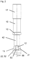
- FIGS. 1 to 4 show an embodiment of an inventive expansion anchor.
- the expansion anchor has an anchor bolt 10 with a longitudinal axis 99 and an expansion sleeve 30, wherein the expansion sleeve 30 surrounds the anchor bolt 10 in an annular manner.
- the anchor bolt 10 has a neck region 14 with at least approximately constant cross section. Following the neck region 14, the anchor bolt 10 in front of the neck region 14, in the front end region of the anchor bolt 10, an expansion body 15 for the expansion sleeve 30, which is here exemplified integrally with the rest of the anchor bolt 10.
- the anchor bolt 10 widens on its outer surface starting from the neck region 14 towards the front, that is to say the expansion body 15 converges on its outside toward the rear.
- the expansion sleeve 30 surrounds the neck region 14 of the anchor bolt 10.
- the expansion body 15 is arranged for the most part in front of the expansion sleeve 30.
- the anchor bolt 10 further includes a sleeve stopper 13, for example designed as a circular ring, which limits an axial movement of the expansion sleeve 30 towards the rear end of the anchor bolt 10, that is to say an axial movement of the expansion sleeve 30 away from the expansion body 15.
- a sleeve stopper 13 for example designed as a circular ring, which limits an axial movement of the expansion sleeve 30 towards the rear end of the anchor bolt 10, that is to say an axial movement of the expansion sleeve 30 away from the expansion body 15.
- the anchor bolt 10 has a load-engaging structure 17, here represented for example as an external thread, for introducing tensile forces into the anchor bolt 10.
- a nut On this external thread, a nut, not shown, may be arranged with a corresponding internal thread.
- the expansion sleeve 30 has expansion tongues 31 and anchor tongues 32, which are arranged on the front side of the expansion sleeve 30. Both the expansion tongues 31 and the anchor tongues 32 point axially forward.
- the expansion tongues 31 are a bit further forward as the anchor tongues 32, that is, the free Spreizzacheenden 33 are a bit far in front of the free anchor tongue ends 34. But also a flush arrangement or an arrangement in which the anchor tongues 32 further forward than the Spreizzache 31, is possible.
- Adjacent tongues 31, 32 are separated by slots 42 which, starting from the front end side of the expansion sleeve 30, which faces the expansion body 15, extend axially rearwardly into the expansion sleeve 30.
- the expansion tongues 31 and the anchor tongues 32 are free at their respective front and at their respective longitudinal sides and connected to each other at their respective rear sides.
- the armature tongues 32 each have a projection 36 which projects radially outwardly a small distance compared to the adjacent region of the respective armature tongue 32, and which is deflected radially by a bend of the free armature tongue end 34 of the respective armature tongue 32 outside is formed.
- Each of the projections 36 forms a radially outwardly facing claw of the respective anchor tongue 32.
- the projections 36 are given in particular in longitudinal section.
- the expansion tongues 31 on their outer side each have a step-shaped in longitudinal section, radially reaching into the expansion tongue 31 recess 35.
- the recess is open axially forward and backward through a shoulder of the limited expansion sprain, wherein the shoulder forms the riser of the stepped recess 35.
- Behind the recess 35 in the present embodiment on the radial outer side of the expansion sleeve 30 is still a radially extending into the expansion sleeve 30, extending in the circumferential direction groove 39 is provided.
- Sp St Dretti bevels 21 are formed on the expansion body 15 for the expansion tongues 31, which are arranged in front of the expansion tongues 31 axially. At this spreading bevels 21, the cross section of the anchor bolt 10 increases towards the front.
- the expansion bevels 21 can urge the expansion tongues 31 radially outwards when the anchor bolt 10 is displaced to the rear relative to the expansion sleeve 30 and the expansion tongues 31 accumulate on the expansion slopes 21.
- the spreading bevels 21 here form sections of a cone sheath.
- anchor slopes 22 are formed for the anchor tongues 32.
- the anchor slopes 22 may urge the anchor tongue 32 disposed in the associated trough 12 radially outward when the anchor bolt 10 is displaced rearwardly relative to the expansion sleeve 30 and the anchor tongues 32 thereby run onto the anchor slopes 22.
- the anchor slopes 22 are arranged in their respective rear portion 52 less steeply to the longitudinal axis 99 than in their respective front portion 53, that is, the anchor slopes 22 close with the longitudinal axis 99 of the anchor bolt 10 in their respective front portion 53 a larger maximum acute angle than
- the anchor slopes 22 in their respective front portion 53 are steeper to the longitudinal axis 99 than the Sp Schwarzschrägen 21, and arranged in their respective rear portion 52 less steeply to the longitudinal axis 99 than the Sp
- the expansion tongues 31 are initially primarily displaced radially. As the anchorage progresses, however, the anchor tongue 32 impinge on the steeper front region 53 of the respective armature bevel 22 and are then also reinforced radially displaced.
Landscapes
- Engineering & Computer Science (AREA)
- General Engineering & Computer Science (AREA)
- Mechanical Engineering (AREA)
- Dowels (AREA)
Priority Applications (2)
| Application Number | Priority Date | Filing Date | Title |
|---|---|---|---|
| EP18159869.9A EP3536986A1 (fr) | 2018-03-05 | 2018-03-05 | Ancrage expansible doté de la douille expansible à languettes différentes |
| PCT/EP2019/054930 WO2019170505A1 (fr) | 2018-03-05 | 2019-02-28 | Système d'ancrage à expansion comprenant une douille à expansion dotée de différentes languettes |
Applications Claiming Priority (1)
| Application Number | Priority Date | Filing Date | Title |
|---|---|---|---|
| EP18159869.9A EP3536986A1 (fr) | 2018-03-05 | 2018-03-05 | Ancrage expansible doté de la douille expansible à languettes différentes |
Publications (1)
| Publication Number | Publication Date |
|---|---|
| EP3536986A1 true EP3536986A1 (fr) | 2019-09-11 |
Family
ID=61563249
Family Applications (1)
| Application Number | Title | Priority Date | Filing Date |
|---|---|---|---|
| EP18159869.9A Withdrawn EP3536986A1 (fr) | 2018-03-05 | 2018-03-05 | Ancrage expansible doté de la douille expansible à languettes différentes |
Country Status (2)
| Country | Link |
|---|---|
| EP (1) | EP3536986A1 (fr) |
| WO (1) | WO2019170505A1 (fr) |
Families Citing this family (1)
| Publication number | Priority date | Publication date | Assignee | Title |
|---|---|---|---|---|
| EP4074990A1 (fr) * | 2021-04-13 | 2022-10-19 | Hilti Aktiengesellschaft | Ancrage d'expansion |
Citations (9)
| Publication number | Priority date | Publication date | Assignee | Title |
|---|---|---|---|---|
| DE2256822A1 (de) | 1972-11-20 | 1974-06-06 | Manfred Dipl Ing Jost | Anker, insbesondere duebel |
| DE2701510A1 (de) * | 1977-01-15 | 1978-07-20 | Upat Max Langensiepen Kg | Duebel mit huelse und spreizkoerper |
| EP0019782A2 (fr) * | 1979-05-31 | 1980-12-10 | Albert Berner GmbH & Co KG | Cheville métallique creuse |
| CH688061A5 (de) * | 1992-12-07 | 1997-04-30 | Mungo Befestigungstech Ag | Ankerbolzen. |
| JP2007154914A (ja) * | 2005-11-30 | 2007-06-21 | Nippon Eisei Center:Kk | 耐震拡開アンカー |
| EP2309138A2 (fr) | 2009-10-06 | 2011-04-13 | HILTI Aktiengesellschaft | Piton à expansion |
| WO2012126700A1 (fr) | 2011-03-23 | 2012-09-27 | Hilti Aktiengesellschaft | Boulon d'ancrage et procédé de fabrication |
| EP2848825A1 (fr) | 2013-09-16 | 2015-03-18 | HILTI Aktiengesellschaft | Ancre extensible |
| WO2015067578A1 (fr) | 2013-11-06 | 2015-05-14 | Hilti Aktiengesellschaft | Cheville expansible munie de stries sur le cône expansible |
-
2018
- 2018-03-05 EP EP18159869.9A patent/EP3536986A1/fr not_active Withdrawn
-
2019
- 2019-02-28 WO PCT/EP2019/054930 patent/WO2019170505A1/fr not_active Ceased
Patent Citations (9)
| Publication number | Priority date | Publication date | Assignee | Title |
|---|---|---|---|---|
| DE2256822A1 (de) | 1972-11-20 | 1974-06-06 | Manfred Dipl Ing Jost | Anker, insbesondere duebel |
| DE2701510A1 (de) * | 1977-01-15 | 1978-07-20 | Upat Max Langensiepen Kg | Duebel mit huelse und spreizkoerper |
| EP0019782A2 (fr) * | 1979-05-31 | 1980-12-10 | Albert Berner GmbH & Co KG | Cheville métallique creuse |
| CH688061A5 (de) * | 1992-12-07 | 1997-04-30 | Mungo Befestigungstech Ag | Ankerbolzen. |
| JP2007154914A (ja) * | 2005-11-30 | 2007-06-21 | Nippon Eisei Center:Kk | 耐震拡開アンカー |
| EP2309138A2 (fr) | 2009-10-06 | 2011-04-13 | HILTI Aktiengesellschaft | Piton à expansion |
| WO2012126700A1 (fr) | 2011-03-23 | 2012-09-27 | Hilti Aktiengesellschaft | Boulon d'ancrage et procédé de fabrication |
| EP2848825A1 (fr) | 2013-09-16 | 2015-03-18 | HILTI Aktiengesellschaft | Ancre extensible |
| WO2015067578A1 (fr) | 2013-11-06 | 2015-05-14 | Hilti Aktiengesellschaft | Cheville expansible munie de stries sur le cône expansible |
Also Published As
| Publication number | Publication date |
|---|---|
| WO2019170505A1 (fr) | 2019-09-12 |
Similar Documents
| Publication | Publication Date | Title |
|---|---|---|
| EP2309138B1 (fr) | Piton à expansion | |
| EP3047162B1 (fr) | Ancre extensible | |
| EP3060816B1 (fr) | Ancrage expansible doté d'une douille expansible haute résistance sur certaines zones | |
| EP3274596B1 (fr) | Cheville à expansion | |
| EP3074644A1 (fr) | Élément d'ancrage expansible à coefficient de frottement anisotrope | |
| DE3124823A1 (de) | Spreizduebel | |
| EP3365565A1 (fr) | Procédé de fixation d'un élément d'ancrage à expansion sur un substrat, selon lequel une matière durcissable est introduite dans l'espace annulaire autour l'élément d'ancrage à expansion | |
| WO2014166787A1 (fr) | Système d'ancrage comprenant une partie expansible et un filetage coupant | |
| EP3728871B1 (fr) | Élément d'ancrage à expansion pourvu d'une rainure annulaire élargie au niveau de la douille à expansion | |
| DE3006480C2 (fr) | ||
| EP3762622A1 (fr) | Élément d'ancrage extensible avec corps d'expansion supplémentaire | |
| EP3536986A1 (fr) | Ancrage expansible doté de la douille expansible à languettes différentes | |
| EP3762623B1 (fr) | Ancrage expansible ayant différents angles d'expansion | |
| DE19848704A1 (de) | Hinterschnittdübel | |
| DE102007036349A1 (de) | Montageeinheit, Befestigereinheit und Verfahren zur Herstellung einer Montageeinheit | |
| EP3728872B1 (fr) | Élément d'ancrage à expansion pourvu d'une rainure annulaire adaptée à une douille à expansion | |
| WO2019166256A1 (fr) | Élément d'ancrage à expansion à douille d'ancrage en expansion vers l'arrière | |
| DE102011087548A1 (de) | Spreizanker | |
| WO2022089872A1 (fr) | Ancrage en contre-dépouille | |
| DE102011087549A1 (de) | Spreizanker |
Legal Events
| Date | Code | Title | Description |
|---|---|---|---|
| PUAI | Public reference made under article 153(3) epc to a published international application that has entered the european phase |
Free format text: ORIGINAL CODE: 0009012 |
|
| AK | Designated contracting states |
Kind code of ref document: A1 Designated state(s): AL AT BE BG CH CY CZ DE DK EE ES FI FR GB GR HR HU IE IS IT LI LT LU LV MC MK MT NL NO PL PT RO RS SE SI SK SM TR |
|
| AX | Request for extension of the european patent |
Extension state: BA ME |
|
| STAA | Information on the status of an ep patent application or granted ep patent |
Free format text: STATUS: THE APPLICATION IS DEEMED TO BE WITHDRAWN |
|
| 18D | Application deemed to be withdrawn |
Effective date: 20200312 |