EP3537108B1 - Référence de données de vol multiples pour une sélection spécifique sur un affichage vertical et latéral - Google Patents
Référence de données de vol multiples pour une sélection spécifique sur un affichage vertical et latéral Download PDFInfo
- Publication number
- EP3537108B1 EP3537108B1 EP19160659.9A EP19160659A EP3537108B1 EP 3537108 B1 EP3537108 B1 EP 3537108B1 EP 19160659 A EP19160659 A EP 19160659A EP 3537108 B1 EP3537108 B1 EP 3537108B1
- Authority
- EP
- European Patent Office
- Prior art keywords
- flight
- display
- section
- flight parameter
- vsd
- Prior art date
- Legal status (The legal status is an assumption and is not a legal conclusion. Google has not performed a legal analysis and makes no representation as to the accuracy of the status listed.)
- Active
Links
Images



Classifications
-
- G—PHYSICS
- G01—MEASURING; TESTING
- G01C—MEASURING DISTANCES, LEVELS OR BEARINGS; SURVEYING; NAVIGATION; GYROSCOPIC INSTRUMENTS; PHOTOGRAMMETRY OR VIDEOGRAMMETRY
- G01C23/00—Combined instruments indicating more than one navigational value, e.g. for aircraft; Combined measuring devices for measuring two or more variables of movement, e.g. distance, speed or acceleration
-
- G—PHYSICS
- G01—MEASURING; TESTING
- G01C—MEASURING DISTANCES, LEVELS OR BEARINGS; SURVEYING; NAVIGATION; GYROSCOPIC INSTRUMENTS; PHOTOGRAMMETRY OR VIDEOGRAMMETRY
- G01C23/00—Combined instruments indicating more than one navigational value, e.g. for aircraft; Combined measuring devices for measuring two or more variables of movement, e.g. distance, speed or acceleration
- G01C23/005—Flight directors
-
- G—PHYSICS
- G08—SIGNALLING
- G08G—TRAFFIC CONTROL SYSTEMS
- G08G5/00—Traffic control systems for aircraft
- G08G5/20—Arrangements for acquiring, generating, sharing or displaying traffic information
- G08G5/21—Arrangements for acquiring, generating, sharing or displaying traffic information located onboard the aircraft
-
- G—PHYSICS
- G08—SIGNALLING
- G08G—TRAFFIC CONTROL SYSTEMS
- G08G5/00—Traffic control systems for aircraft
- G08G5/30—Flight plan management
-
- G—PHYSICS
- G08—SIGNALLING
- G08G—TRAFFIC CONTROL SYSTEMS
- G08G5/00—Traffic control systems for aircraft
- G08G5/30—Flight plan management
- G08G5/34—Flight plan management for flight plan modification
-
- G—PHYSICS
- G08—SIGNALLING
- G08G—TRAFFIC CONTROL SYSTEMS
- G08G5/00—Traffic control systems for aircraft
- G08G5/50—Navigation or guidance aids
- G08G5/53—Navigation or guidance aids for cruising
-
- G—PHYSICS
- G08—SIGNALLING
- G08G—TRAFFIC CONTROL SYSTEMS
- G08G5/00—Traffic control systems for aircraft
- G08G5/50—Navigation or guidance aids
- G08G5/55—Navigation or guidance aids for a single aircraft
-
- G—PHYSICS
- G08—SIGNALLING
- G08G—TRAFFIC CONTROL SYSTEMS
- G08G5/00—Traffic control systems for aircraft
- G08G5/70—Arrangements for monitoring traffic-related situations or conditions
- G08G5/72—Arrangements for monitoring traffic-related situations or conditions for monitoring traffic
- G08G5/723—Arrangements for monitoring traffic-related situations or conditions for monitoring traffic from the aircraft
Definitions
- the present invention generally relates to mobile platform display systems, and more particularly relates to methods and systems that generate multiple flight data references for a specific selected section on a vertical and lateral display.
- VSD vertical situation display
- ND lateral navigation display
- the user wishes to analyze multiple flight data (or specific flight parameters) along the selected section, but this flight data is either not available, or is not displayed in a useful manner.
- this flight data is either not available, or is not displayed in a useful manner.
- the user may have to spend additional time visually mapping a portion of the flight plan on the VSD and then finding corresponding information on the ND.
- this exercise requires navigating through multiple modes and window range sizes, which adds to head down time and increases cognitive demand.
- Desired display systems and methods respond to user selections of a section of a flight plan, those user selections being made on either the VSD or the ND.
- the desired display systems and methods provide multiple specific flight data (i.e., flight parameter information) for the selected section.
- EP2362289A2 disclose systems and methods for presenting operating information for an aircraft in a vertical profile displayed on a display device associated with the aircraft.
- the vertical profile graphically depicts at least a portion of a flight plan for the aircraft, wherein the portion of the flight plan includes a plurality of reference points.
- the method involves calculating, for each reference point of the plurality of reference points, a predicted value of a first operating parameter for the aircraft at the respective reference point based at least in part on current status information for the aircraft, resulting in predicted values for the first operating parameter, and displaying the predicted values for the first operating parameter in the vertical profile.
- US20160078770A1 discloses a method of graphical manipulation of the trajectory of an aircraft comprising the steps of receiving an indication of a deformation point associated with the trajectory of the aircraft; determining a zone of local modification of the trajectory of the aircraft as a function of the deformation point; computing a modified trajectory and graphically restoring the modified trajectory.
- a parameter associated with the indication of the deformation point notably a speed and/or acceleration value (for example of the contact point on the touch-sensitive interface, or else of a cursor), is received or determined.
- a modified trajectory is computed by selecting a computation algorithm from among a plurality of faster or slower predefined algorithms; the selection being performed as a function of the parameter.
- US20100332123A1 discloses a method of assisting the piloting of an aircraft at low altitude over terrain, in which method, during a first stage, a framework is constructed from at least one main segment and during a second stage a setpoint flight path is constructed. More precisely, during the first stage, said main segment is subdivided automatically into a plurality of secondary segments, each of said secondary segments being situated at the same setpoint height above the highest point of the underlying terrain, with two adjacent secondary segments being in alignment or connected together by a bar that extends vertically in a vertical section
- a flight display system for an aircraft comprises: a display system configured to render thereon a viewing segment defined as at least a portion of a flight plan for the aircraft, the viewing segment, when rendered, being concurrently presented on (i) a vertical situation display (VSD), and (ii) a lateral navigation display (ND); and a control module comprising a processor and a memory, the control module operationally coupled to the display system and configured to, receive a user input that selects a section of the viewing segment, the user input being received on a first display, the first display being one of the VSD and the ND; visually distinguish the section from the remaining portion of the viewing segment on the VSD and the ND; visually demark a starting point of the section and an ending point of the section on (i) an X axis and (ii) a Y axis, of the VSD; generate a flight parameters window based on the starting point of the section and the ending point of the section, the flight parameters window including, for a first flight parameter:
- a method for a flight display system comprising: at a control module, obtaining current navigation data and current aircraft status data; commanding a vertical situation display (VSD) and a lateral navigation display (ND) to render, concurrently, a viewing segment of a flight plan; receiving a user input selecting a section of the viewing segment, the user input being received on only one of the VSD and the ND; commanding, concurrently, the VSD and the ND to visually distinguish the section; demarking the section with a starting point and an ending point on the VSD; and for a flight parameter, (a) determining which display among the VSD and the ND is appropriate for the rendering of flight parameter information; (b) generating flight system comprising: a display system configured to render thereon a viewing segment defined as at least a portion of a flight plan for the aircraft, the viewing segment, when rendered, being concurrently presented on (i) a vertical situation display (VSD), and (ii) a lateral navigation display (ND); and a control module comprising
- Exemplary embodiments of the novel disclosed flight display system provide a technologically improved flight display system and method that generates and displays multiple flight data (i.e., values for specific flight parameters) for a specific selected section of a flight plan on the VSD and ND.
- the disclosed flight display system 102 accepts a user selection on either the VSD or ND, and concurrently visually distinguishes and labels the selected section on both the VSD and the ND.
- the disclosed flight display system 102 can further provide for multiple selected flight parameters, any combination of: accurate values with respect to an X and a Y axis, value changes, and rates of change, along the selected section.
- the enhancement provided by the disclosed flight display system 102 provides technologic effects, such as allowing a user to quickly view:
- the flight display system 102 (also referred to herein as "system” 102 ) is generally located in a mobile platform 100.
- the mobile platform 100 is an aircraft, and is referred to as aircraft 100.
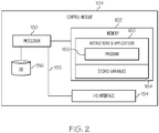
- the flight display system 102 embodies a control module 104.
- the control module 104 may be separate from, or integrated within, a preexisting mobile platform management system, avionics system, cockpit display system (CDS), flight controls system (FCS), aircraft flight management system (FMS), or electronic flight bag (EFB).
- CDS cockpit display system
- FCS flight controls system
- FMS aircraft flight management system
- EFB electronic flight bag
- control module 104 performs the functions of identifying a user selected segment on a first display, concurrently visually distinguishing the user selected segment on the first and a second display, and providing flight parameter information associated with the selected segment.
- control module 104 may be operatively coupled to any combination of the following aircraft systems: a navigation system 110, one or more avionics systems 112, one or more on-board sensor systems 114, a user interface 116, a display system 118, a communications system 120, and one or more data storage elements (DB 1) 122.
- DB 1 data storage elements
- control module 104 is coupled to the navigation system 110, which, as used herein, comprises a flight management system FMS and a flight plan database.
- the navigation system 110 comprises a flight management system FMS and a flight plan database.
- current is interchangeable with real-time and instantaneous.
- the navigation system 110 is configured to provide current navigational data and/or information regarding operation of the aircraft 100, including current flight guidance for aircraft 100.
- the navigation system 110 may be realized as including a global positioning system (GPS), inertial reference system (IRS), or a radio-based navigation system (e.g., VHF omni-directional radio range (VOR) or long range aid to navigation (LORAN)), and may include one or more navigational radios or other sensors suitably configured to support operation of the navigation system 110, as will be appreciated in the art.
- GPS global positioning system
- IRS inertial reference system
- LORAN long range aid to navigation
- the navigation system 110 is capable of obtaining and/or determining the current position of the aircraft 100, that is, (i) the instantaneous location of the aircraft 100 (e.g., the latitude and longitude) and (ii) the instantaneous altitude (or above ground level) for the aircraft 100.
- the navigation system 110 is also capable of obtaining or otherwise determining the instantaneous heading of the aircraft 100 (i.e., the direction the aircraft is traveling in relative to some reference), and to compare the instantaneous position of the aircraft 100 with an intended flight plan for the aircraft 100.
- the various data, information, and guidance, determined by the navigation system 110 are referred to herein as navigation data or as current aircraft status data, and may comprise current phase of flight information.
- Navigation data is made available such that one or more of the other onboard systems 112, 114, 116, 118, 120, and the control module 104, may further process and/or handle the navigation data.
- the avionics system(s) 112 include numerous systems for obtaining and/or providing current flight-related data and information.
- avionics systems 112 may include any combination of: a weather system, an air traffic management system, a radar system, a traffic avoidance system, an autopilot system, an auto thrust system, a flight control system, hydraulics systems, pneumatics systems, environmental systems, electrical systems, engine systems, trim systems, lighting systems, crew alerting systems, electronic checklist systems, an electronic flight bag and/or another suitable avionics system.
- Each of these avionics systems 112 generates respective data; the entirety of data from the avionics system(s) 112 is referred to herein as avionics data.
- Current avionics data is made available such that one or more of the other onboard systems 110, 114, 116, 118, 120, and the control module 104, may further process and/or handle the avionics data.
- the onboard sensor system(s) 114 generally represent the component(s) of the aircraft 100 that sense, detect, or otherwise identify a respective status of various aircraft systems and subsystems.
- the onboard sensor system(s) 114 may sense status of a specific avionics system 112, subsystem, surface, component, line replacement unit (LRU), or the like.
- the sensor system(s) 114 provides sensor data including real-time system status data to one or more of the other onboard systems 110, 112, 116, 118, 120.
- the sensor system(s) 114 also provide a respective status of objects or regions of interest in the vicinity of the aircraft 100.
- an onboard sensor system 114 may be realized as a weather radar system or other weather sensing system that measures, senses, or otherwise detects meteorological conditions in the vicinity of the aircraft 100.
- the sensor data therefore, comprises current data for aircraft systems, objects, and weather.
- the sensor system(s) 114 provides sensor data such that one or more of the other onboard systems 110, 112, 116, 118, 120, and control module 104 may further process and/or handle the sensor data.
- the user interface may include a user input device 130.
- the user input device 130 is coupled to the control module 104, and the user input device 130 and the control module 104 are cooperatively configured to allow a user (e.g., a pilot, co-pilot, or crew member) to interact with the display devices in the display system 118 and/or other elements of the flight display system 102, as described in greater detail below.
- the user input device 130 may be realized as a keypad, touchpad, keyboard, mouse, touch panel (or touchscreen), joystick, knob, line select key or another suitable device adapted to receive input from a user.
- the user input device 130 is configured as a touchpad or touchscreen, it may be integrated with the display system 118.
- the control module 104 may be coupled to a communications system 120, which is configured to support communications between external source(s) 140 and the aircraft 100 via the communications link 143.
- External source(s) 140 may comprise air traffic control (ATC), neighboring aircraft, sources of weather information, and other suitable command centers and ground locations.
- ATC air traffic control
- Non-limiting examples of data received from the external source(s) 140 include, for example, instantaneous (i.e., real time or current) air traffic control (ATC) communications, traffic collision and avoidance system (TCAS) data from other aircraft, automatic dependent surveillance broadcast (ADS-B) data, and weather communications.
- an external data source 140 may be used to load or program a flight plan into the system 102 (generally, into a flight plan database in the navigation system 110 ).
- the communications system 120 and communications link 143 may include a data link system, automatic dependent surveillance broadcast system (ADS-B), a communication management function (CMF) uplink, a terminal wireless local area network (LAN) unit (TWLU), or any other suitable radio communication system that supports communications between the aircraft 100 and the various external source(s) 140.
- ADS-B automatic dependent surveillance broadcast system
- CMS communication management function
- TWLU terminal wireless local area network unit
- the communications system 120 may allow the aircraft 100 to receive information that would otherwise be unavailable to the pilot and/or co-pilot using the onboard systems 110, 112, 114, 116.
- any combination of the navigation system 110, avionics system(s) 112, onboard sensor system(s) 114, and communications system 120 may be coupled to the display system 118 such that the display system 118 may generate or render, on a display device, real-time information associated with the respective components. Coupled in this manner, the navigation system 110, avionics system(s) 112, onboard sensor system(s) 114, and communications system 120 are configured to support navigation, flight planning, and other aircraft control functions in a conventional manner, as well as to provide real-time data and/or information regarding the operational status of the aircraft 100 to the control module 104.
- the renderings of the display system 118 may be processed by a graphics system, components of which may be integrated into the display system 118 and/or be integrated within the control module 104.
- Display methods include various types of computer generated symbols, text, and graphic information representing, for example, pitch, heading, flight path, airspeed, altitude, runway information, waypoints, targets, obstacles, terrain, and required navigation performance (RNP) data in an integrated, multi-color or monochrome form. Display methods also include various techniques for visually distinguishing objects.
- the control module 104 is said to display various images herein.
- control module 104 generates display commands, and responsive to receiving the display commands from the control module 104, the display system 118 displays, renders, or otherwise visually conveys on a display device, one or more graphical representations or images associated with operation of the aircraft 100, and specifically, the multi-function display (MFD) 40 described in greater detail below.
- MFD multi-function display
- the MFD 40 is realized on one or more electronic display devices configured as a combination of a vertical situation display (VSD) and a lateral navigation display (ND).
- VSD vertical situation display
- ND lateral navigation display
- the VSD renders a graphical representation of the aircraft 100 and one or more of the airspace, air traffic, navigational reference points, and a vertical flight plan associated with a flight plan of the aircraft 100.
- the ND renders a top down graphical representation of the aircraft 100 and one or more of the terrain, meteorological conditions, airspace, air traffic, navigational reference points, and a route associated with a lateral flight plan of the aircraft 100.
- Each of the VSD and ND are responsive to display commands from the control module 104 and/or display system 118.
- the control module 104 and the display system 118 are cooperatively configured to generate the display commands for the MFD 40, including the various user interface elements, such as menus and buttons, described below.
- the data storage element or database DB 122 may maintain information regarding terrain and airports and/or other potential landing locations (or destinations) for the aircraft 100.
- the DB 122 maintains an association between a respective airport, its geographic location, runways (and their respective orientations and/or directions), instrument procedures (e.g., approaches, arrival routes, and the like), airspace restrictions, and/or other information or attributes associated with the respective airport (e.g., widths and/or weight limits of taxi paths, the type of surface of the runways or taxi path, and the like).
- the DB 122 also maintains airport status data for the runways and/or taxi paths at the airport indicating whether or not a particular runway and/or taxi path is currently operational along with directional information for the taxi paths (or portions thereof).
- control module 104 performs the functions of the system 102.
- module refers to any hardware, software, firmware, electronic control component, processing logic, and/or processor device, individually or in any combination, configured as a means for facilitating communications and/or interaction between the elements of the flight display system 102 and performing additional processes, tasks and/or functions to support operation of the flight display system 102, as described herein.
- the control module FIG. 1
- 1 , 104) may be implemented or realized with a general purpose processor (shared, dedicated, or group) controller, microprocessor, or microcontroller, and memory that executes one or more software or firmware programs; a content addressable memory; a digital signal processor; an application specific integrated circuit (ASIC), a field programmable gate array (FPGA); any suitable programmable logic device; combinational logic circuit including discrete gates or transistor logic; discrete hardware components and memory devices; and/or any combination thereof, designed to perform the functions described herein.
- a general purpose processor shared, dedicated, or group
- microprocessor or microcontroller
- memory that executes one or more software or firmware programs
- a content addressable memory a digital signal processor
- ASIC application specific integrated circuit
- FPGA field programmable gate array
- any suitable programmable logic device combinational logic circuit including discrete gates or transistor logic; discrete hardware components and memory devices; and/or any combination thereof, designed to perform the functions described herein.
- a processor 150 and a memory 152 form a novel processing engine or unit that performs the processing activities of the system 102.
- the processor 150 may comprise any type of processor or multiple processors, single integrated circuits such as a microprocessor, or any suitable number of integrated circuit devices and/or circuit boards working in cooperation to carry out the described operations, tasks, and functions by manipulating electrical signals representing data bits at memory locations in the system memory, as well as other processing of signals.
- the memory 152 maintains data bits and may be utilized by the processor 150 as storage and/or a scratch pad.
- the memory 152 may be located on and/or co-located on the same computer chip as the processor 150.
- the memory 152 stores instructions and applications 160 and one or more configurable variables in stored variables 164.
- Information in the memory 152 may be organized and/or imported from an external data source 140 during an initialization step of a process; it may also be programmed via a user input device 130.
- a novel program 162 is embodied in the memory 152 (e.g., RAM memory, ROM memory, flash memory, registers, a hard disk, or the like) or another suitable non-transitory short or long term storage media capable of storing computer-executable programming instructions or other data for execution.
- the program 162 includes rules and instructions which, when executed, cause the flight display system 102 to perform the functions, techniques, and processing tasks associated with the operation of the flight display system 102 described herein.
- the processor 150 loads and executes one or more programs, algorithms and rules embodied as instructions and applications 160 contained within the memory 152 and, as such, controls the general operation of the control module 104 as well as the system 102. In executing the process described herein, the processor 150 specifically loads and executes the instructions embodied in the program 162.
- the processor 150 is configured to, in accordance with the program 162: process received inputs (selectively, any combination of input from the set including: external data sources 140, the navigation system 110, avionics system(s) 112, on-board sensor system(s) 114, the user interface 116, the display system 118, and the communications system 120); reference any of the databases; determine various flight parameters; and, generate display commands that command and control the display system 118.
- process received inputs (selectively, any combination of input from the set including: external data sources 140, the navigation system 110, avionics system(s) 112, on-board sensor system(s) 114, the user interface 116, the display system 118, and the communications system 120); reference any of the databases; determine various flight parameters; and, generate display commands that command and control the display system 118.
- the processor/memory unit of the control module 104 may be communicatively coupled (via a bus 155 ) to an input/output (I/O) interface 154, and a database 156.
- the bus 155 serves to transmit programs, data, status and other information or signals between the various components of the control module 104.
- the bus 155 can be any suitable physical or logical means of connecting computer systems and components. This includes, but is not limited to, direct hard-wired connections, fiber optics, infrared and wireless bus technologies.
- the I/O interface 154 enables communications between the control module 104 and other system 102 components, as well as with other external data sources 140 not already addressed herein, and as well as within the control module 104, can include one or more network interfaces to communicate with other systems or components.
- the I/O interface 154 can be implemented using any suitable method and apparatus.
- the I/O interface 154 supports communication from a system driver and/or another computer system.
- the I/O interface 154 obtains data from external data source(s) 140 directly.
- the I/O interface 154 may also include one or more network interfaces to communicate with technicians, and/or one or more storage interfaces for direct connection to storage apparatuses, such as the database 156.
- the database 156 may include an aircraft-specific parameters database (comprising aircraft-specific parameters for a variety of aircrafts) and parameters and instructions for processing user inputs and rendering images on the MFD 40, as described herein.
- the database 156 is part of the memory 152.
- the database 156 and the database 122 are integrated, either within the control module 104 or external to the control module 104.
- the images displayed on the MFD 40 are understood to be based on current aircraft status data for the aircraft 100 and to be dynamically updated based on continuously obtaining the current aircraft status data.
- a "viewing segment" is at least a portion of a flight plan for the aircraft 100; each MFD 40 image depicts the same viewing segment on each of the VSD and ND.
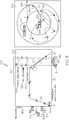
- FIG. 3 depicts a MFD image 300 that may be generated in accordance with various embodiments.
- MFD image 300 includes viewing segment 20 rendered on the VSD 302 image and viewing segment 22 rendered on the ND 304 image, wherein viewing segment 20 and viewing segment 22 each provide different views of the same portion of the flight plan (in this example, the entire flight plan from origin to destination).
- Aircraft 100 is depicted on each of the VSD 302 (at 306 ) and ND 304 (at 308 ) to provide reference for the respective viewing segment.
- FIG. 3 depicts a user input on the VSD 302, selecting a section 310 of the viewing segment.
- section 310 is a portion of the viewing segment in which the aircraft is to be descending toward its destination.
- the control module 104 determines the corresponding section on the second display, which is section 312, and concurrently visually distinguishes the section 310 from the remaining portion of the viewing segment on the VSD 302 and the section 312 from the remaining portion of the viewing segment on the ND 304.
- Techniques for visually distinguishing sections may include highlighting, changing line widths, changing colors, and the like.
- control module 104 also, responsive thereto, visually demarks, with an alphanumeric value, a starting point of the section 310 and an ending point of the section 310; these points are, respectively, (i) an X axis ( 314 , 316 ) and (ii) a Y axis ( 320 , 18 ), of the VSD 302.
- control module 104 also determines and displays a delta distance 322 ( 316 - 314 ) and a delta altitude 324 ( 320-318 ), along the respective axis, on the VSD 302. For example, in FIG. 3 , the delta distance 322 is 110 nautical miles, and the delta altitude is 12,100 feet.
- Flight parameter information may include (1) a predicted change in the flight parameter value from the starting point to the ending point, and/or (2) a rate of change of the flight parameter from the starting point to the ending point. Any combination of the below flight parameters may be selected.
- the below table presents a non limiting example of flight parameters that the user may select for display. Table 1.
- Flight Parameters Flight Parameters Calibrated Air Speed (in Knots) Total Fuel Remaining (in LBS) Gross weight (in LBs) Time / ETA (in HH:MM) Fuel weight (in LBS) Mach Speed Target (in Knots) Fuel Flow (in LBS / Hour) Flight Path Angle (In Degrees) Drag (in Newton) Lift (in Newton) Minimum Calibrated Air Speed (in Knots) Maximum Calibrated Air Speed (in Knots) Speed Brake Position ISA Deviation (in Deg Celsius) Minimum envelope Altitude (in Feet) Maximum Envelope Altitude (in Feet) Wind (in Knots) Ferry Fuel Tank Fuel Quantity (in LBS) Current Temperature (in Deg Celsius)
- the selected flight parameters are: total fuel remaining 326, time/estimated time of arrival (ETA) 328, and a speed target (in Knots) 330.
- the control module 104 processes each selected flight parameter with the novel rules embedded in the program 162, and user selections, to determine whether to generate flight parameter information comprising a rate of change or values along the section ( 310, 312 ), and then generates the flight parameter information for the selected flight parameter.
- the control module 104 provides the generated flight parameter information in a flight parameters window 350.
- the flight parameter window 350 includes, for each selected flight parameter, an alphanumeric label, and a graphical representation of the rate of change or values along the selected section, for each of the selected flight parameters. Flight parameters window 350 is overlaid on the VSD 302 such that it is near the viewing segment 20, but not obscuring the viewing segment.
- the control module 104 aligns the flight parameter window 350 and its information with the selected section 310 on the X axis (as can be seen in FIG. 3 , the graphical representations of the values of each of the flight parameters are aligned to begin at the starting point 314 of the section 310 and end at the ending point 316 of the section 310 ).
- control module 104 continually (i) commands the display system 118 to overlay, on the VSD 302, the flight parameters window 350; (ii) obtains current aircraft status data for the aircraft 100; and (iii) dynamically updates the VSD 302, the ND 304, and the flight parameters window 350 based on continuously obtaining the current aircraft status data for the aircraft 100.
- values for one or more flight parameters along the selected section 312 are also determined by the control module 104 and displayed, alphanumerically, on the ND 304.
- the starting point is 352, having associated therewith an alphanumeric value for a banking angle 354 (310 degrees), and the ending point is 356, having associated therewith a banking angle 358 (276 degrees).
- Other parameters that may be displayed or overlaid on the ND 304 include the course of the wind at the starting point 352 and at the ending point 356.
- the flight parameters selected for display on the VSD 302 or ND 304 may be selected in a variety of ways.
- a user interface element such as a menu, buttons, or the like
- the control module 104 generates and displays a flight data menu 402 on the MFD 40.
- the user views the flight data menu 402, and selects or adds (for display) or deselects or deletes (to remove from display) one or more flight parameters.
- the control module processes the user selection and dynamically updates the images on the MFD 40 responsive thereto.
- FIG. 4 a user interface element (such as a menu, buttons, or the like) is used for prompting a user to perform an action such as to add or delete a flight parameter.
- the control module 104 generates and displays a flight data menu 402 on the MFD 40.
- the user views the flight data menu 402, and selects or adds (for display) or deselects or deletes (to remove from display) one or more flight parameters.
- the control module processes the user selection
- total fuel remaining 404, time/ETA 406 and speed target 408 is shown selected.
- the total fuel remaining is shown as a generally linear rate of change from 2000 to 1150 pounds along the section 310 at 326
- the Time/ETA is shown at 328 with a lateral dashed line connecting 15:22 and 16:05
- the speed target in Knots is shown at 330 as 280 at the starting point 314, the rate of change shown as dropping to 220 at some point prior to the ending point 316.
- buttons 502, 504 to individually add and delete flight parameters on the MFD 40.
- Buttons 502 are shown aligned laterally, one per displayed flight parameter ( 326, 328, 330 ), allowing a user to delete the respective flight parameter ( 326, 328, 330 ).
- Button 504 allows the user to selectively choose additional flight parameters to display in the flight parameters window 350.
- a graphical user interface element is displayed and used for prompting a user to perform at least one action from the set including, (i) add a flight parameter to the flight parameters window, and (ii) delete a flight parameter from the flight parameters window.
- the program 162 comprises rules determining whether to render a flight parameter on the VSD 302 or the ND 304.
- the rules take into account the display area of the ND 304 and the nature of the flight parameter; based thereon, the control module 104 processes each user selected flight parameter and determines whether to render it on the VSD 302 or the ND 304.
- flight parameters determined to be displayed on the ND 304 are overlaid on the ND 304 such that it is near the viewing segment 22, but not obscuring the viewing segment.
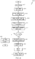
- the flight display system 102 may be used to implement a method 600, as shown in the flow chart of FIG. 6 .
- method 600 may refer to elements mentioned above in connection with FIGS. 1-2 .
- portions of method 600 may be performed by different components of the described system.
- method 600 may include any number of additional or alternative tasks, the tasks shown in FIG. 6 need not be performed in the illustrated order, and method 600 may be incorporated into a more comprehensive procedure or method having additional functionality not described in detail herein.
- one or more of the tasks shown in FIG. 6 could be omitted from an embodiment of the method 600 as long as the intended overall functionality remains intact.
- Initialization generally comprises uploading or updating instructions and applications as required for operation of the flight display system 102. This may include: the executable program 162; the DB 122; and, any associated stored variables 164.
- the control module 104 receives current aircraft status data for the aircraft 100.
- a viewing segment is rendered on MFD 40.
- the viewing segment is rendered as a vertical view in VSD 302 and as a lateral view, as ND 304.
- the method 600 identifies a user input that selects a section of the viewing segment.
- the user input is received on a first display, the first display being one of the VSD 302 and the ND 304.
- the section is visually distinguished from the remaining portion of the viewing segment on the VSD 302 and the ND 304; this is regardless of which display the user input is received from.
- a starting point of the section 310 and an ending point of the section 310 are visually demarked on (i) an X axis and (ii) a Y axis, of the VSD 302.
- the method 600 may also determine and display a delta distance 322 ( 316-314 ) and a delta altitude 324 ( 320-318 ), along the respective axis, on the VSD 302.
- the method 600 proceeds to 616 to continually update the VSD 302 and the ND 304 during aircraft operation or until receiving another user input at 608.
- the method 600 removes or deletes any visual distinctions or parameter selections from the previous user selection.
- the method 600 proceeds to 618 to obtain the relevant avionics data and/or sensor data.
- the method 600 determines which display is appropriate for the display of the selected FP information; this determination may be based on display dimensions and the nature of the FP (i.e., some flight parameters naturally lend themselves to a vertical display and others to a lateral display).
- the FP information is generated based on the relevant avionics data and/or sensor data, and the determined appropriate display.
- the FP information for display on the VSD 302 includes: the flight parameters window 350 is generated based on the starting point 314 of the section 310 and the ending point 316 of the section 310, the flight parameters window 350 including, for a flight parameter, (a) a respective alphanumeric value at the starting point 314 of the section 310, (b) a graphical representation of a rate of change (or values) between the starting point 314 of the section 310 and the ending point 316 of the section 310, and (c) an alphanumeric value at the ending point 316 of the section 310.
- the FP information for display on the ND 304 includes (a) a respective alphanumeric value at the starting point 352 of the section 312, and (c) an alphanumeric value at the ending point 316 of the section 310.
- the FP information generated at 622 is overlaid on the respective display (i.e., the VSD 302 or the ND 304 ) as described herein.
- a user may interact with the flight display system 102 and add (i.e., select additional) FPs, or delete FPs.
- the method 600 repeats 618, 620, and 622 for each FP, accumulating each of the generated FP information in memory 152.
- the control module commands the display system 118 to overlay, on the respective display, the FP information. Multiple FPs are displayed on the VSD 302 such that each is aligned within the FP window 350 as described herein. Subsequent to overlaying the FP information on the respective display at 624, the method 600 proceeds to 616 to continually update the VSD 302 and the ND 304 during aircraft operation or until receiving another user input at 608.
- the exemplary embodiments discussed above provide a technologically improved flight display system 102 and method that generates multiple flight data for a specific selected section of a flight plan on the VSD and ND.
- the disclosed flight display system 102 accepts a user selection on either the VSD or ND, and concurrently visually distinguishes and labels the selected section on both the VSD and the ND.
- the disclosed flight display system 102 allows a user to select desired flight parameters to display, and displays, for each selected parameter, any combination of: accurate values with respect to an X and a Y axis, value changes, and rates of change, along the selected section.
Landscapes
- Engineering & Computer Science (AREA)
- Aviation & Aerospace Engineering (AREA)
- Physics & Mathematics (AREA)
- General Physics & Mathematics (AREA)
- Radar, Positioning & Navigation (AREA)
- Remote Sensing (AREA)
- Traffic Control Systems (AREA)
- Navigation (AREA)
Claims (8)
- Système d'affichage de vol (102) pour un aéronef (100) comprenant :un système d'affichage (118) configuré pour restituer sur celui-ci un segment de visualisation défini comme au moins une partie d'un plan de vol pour l'aéronef, le segment de visualisation, lorsqu'il est restitué, étant présenté simultanément sur (i) un affichage de situation vertical (VSD) (20) et (ii) un affichage de navigation latéral (ND) (22) ; etun module de commande (104) comprenant un processeur (150) et une mémoire (152), le module de commande (104) étant couplé opérationnellement au système d'affichage et configuré pour,recevoir une entrée utilisateur qui sélectionne une section du segment de visualisation (310), l'entrée utilisateur étant reçue sur un premier affichage, le premier affichage étant seulement un élément parmi le VSD (20) ou le ND (22) ;distinguer visuellement la section (310) de la partie restante du segment de visualisation sur chacun des VSD (20) et ND (22) simultanément ;marquer visuellement un point de départ (352) de la section (310) et un point d'arrivée (356) de la section (310) sur (i) un axe X représentant un axe de distance et (ii) un axe Y représentant un axe d'altitude, du VSD :générer une fenêtre de paramètres de vol (350) basée sur le point de départ (352) de la section (310) et le point d'arrivée (356) de la section (310), la fenêtre de paramètres de vol (350) comprenant, pour un premierparamètre de vol (326, 328, 330) ;
une valeur alphanumérique au point de départ de la section, une représentation graphique d'un taux de variation entre le point de départ de la section et le point d'arrivée de la section et une valeur alphanumérique au point d'arrivée de la section ;commander au système d'affichage de superposer, sur le VSD, la fenêtre de paramètres de vol (350) ;obtenir des données de navigation actuelles et des données d'état d'aéronef pour l'aéronef ;mettre à jour simultanément le VSD (20), le ND et la fenêtre de paramètres de vol (350) sur la base de l'obtention continue des données d'état actuel de l'aéronef ;commander au système d'affichage de restituer un élément d'interface utilisateur graphique (402, 502, 504) sur le VSD pour inviter un utilisateur à effectuer sélectivement au moins une action parmi l'ensemble comprenant (i) l'ajout d'un paramètre de vol et (ii) la suppression d'un paramètre de vol ;dans lequel le module de commande (104) est en outre configuré pour recevoir un second paramètre de vol ajouté par l'utilisateur ;déterminer l'affichage qui est approprié pour l'affichage d'informations de paramètres de vol pour le second paramètre de vol ;générer des informations de paramètres de vol pour le second paramètre de vol ; etsuperposer les informations de paramètres de vol pour le second paramètre de vol sur l'affichage déterminé comme approprié pour l'affichage des informations de second paramètre de vol. - Système d'affichage de vol selon la revendication 1, dans lequel le premier paramètre de vol est un paramètre parmi une pluralité de paramètres de vol et dans lequel le module de commande (104) est en outre configuré pour :générer la fenêtre de paramètres de vol (350), de telle sorte qu'elle comprenne,pour chaque paramètre de vol de la pluralité de paramètres de vol :
une valeur alphanumérique au point de départ (352) de la section (310), une représentation graphique d'un taux de variation entre le point de départ (352) de la section et le point d'arrivée (356) de la section (310) et une valeur alphanumérique au point d'arrivée (356) de la section (310). - Système d'affichage de vol selon la revendication 1, dans lequel le module de commande (104) est configuré pour déterminer l'affichage qui est approprié sur la base d'un ou plusieurs des éléments suivants : dimensions d'affichage, données aéronefiques et données de capteur.
- Système d'affichage de vol selon la revendication 2, dans lequel le module de commande (104) est en outre configuré pour :recevoir un paramètre de vol supprimé par l'utilisateur ; etsupprimer, de la fenêtre de paramètres de vol (350), des informations de paramètres de vol associées au paramètre de vol supprimé par l'utilisateur.
- Procédé pour un système d'affichage de vol, comprenant :
au niveau d'un module de commande,l'obtention de données d'état actuelles d'aéronef (604) et de données de navigation ;la commande d'un affichage de situation vertical (VSD) (20) et d'un affichage de navigation latéral (ND) pour restituer, simultanément, un segment de visualisation d'un plan de vol (606) ;la réception d'une entrée utilisateur sélectionnant une section du segment de visualisation (608), l'entrée utilisateur étant reçue sur un seul élément parmi le VSD ou le ND ;la commande, simultanément, du VSD et du ND pour distinguer visuellement la section (610) ;le marquage de la section avec un point de départ et un point d'arrivée sur (i) un axe X représentant un axe de distance et (ii) un axe Y représentant un axe d'altitude, sur le VSD (612) ; etla génération d'une fenêtre de paramètres de vol (350) basée sur le point de départ (352) de la section (310) et le point d'arrivée (356) de la section (310), la fenêtre de paramètres de vol (350) comprenant, pour un premier paramètre de vol prescrit par l'utilisateur, des informations de paramètre de vol comprenant une valeur alphanumérique au point de départ de la section, une représentation graphique d'un taux de variation entre le point de départ de la section et le point d'arrivée de la section et une valeur alphanumérique au point d'arrivée de la section ;la commande donnée au système d'affichage de superposer (624), sur le VSD, la fenêtre de paramètres de vol ;la mise à jour simultanément du VSD, du ND et de la fenêtre de paramètres de vol sur la base de l'obtention continue des données d'état actuelles de l'aéronef et des données de navigation pour l'aéronef ;la commande, donnée au système d'affichage, de restituer un élément d'interface utilisateur graphique sur le VSD pour inviter un utilisateur à effectuer sélectivement au moins une action parmi l'ensemble comprenant (i) l'ajout d'un paramètre de vol et (ii) la suppression d'un paramètre de vol ;le procédé comprenant en outrela réception d'un second paramètre de vol ajouté par l'utilisateur ;la détermination de l'affichage qui est approprié pour l'affichage d'informations de paramètres de vol pour le second paramètre de vol ;la génération d'informations de paramètres de vol pour le second paramètre de vol ; etla superposition des informations de paramètres de vol pour le second paramètre de vol sur l'affichage déterminé comme approprié pour l'affichage d'informations de second paramètre de vol. - Procédé selon la revendication 5, dans lequel le premier paramètre de vol est un paramètre parmi une pluralité de paramètres de vol et comprenant en outre, pour chaque paramètre de vol de la pluralité de paramètres de vol, la détermination de l'affichage, parmi le VSD et le ND, qui est approprié pour l'affichage d'informations de paramètres de vol pour le paramètre de vol ;
la génération d'informations de paramètres de vol pour le paramètre de vol ; et
la superposition d'informations de paramètres de vol pour le paramètre de vol sur l'affichage déterminé comme approprié pour l'affichage des informations de paramètres de vol. - Procédé selon la revendication 6, comprenant en outre :
la réception d'un paramètre de vol supprimé par l'utilisateur et, pour le paramètre de vol supprimé, la suppression, à partir de l'affichage approprié, des informations de paramètres de vol associées au paramètre de vol supprimé par l'utilisateur. - Procédé selon la revendication 5, comprenant en outre la détermination de l'affichage approprié sur la base d'un ou plusieurs des éléments suivants : dimensions de l'affichage, données aéronefiques et données de capteur.
Applications Claiming Priority (1)
| Application Number | Priority Date | Filing Date | Title |
|---|---|---|---|
| US15/912,942 US10706726B2 (en) | 2018-03-06 | 2018-03-06 | Multiple flight data reference for a specific selection on a vertical and lateral display |
Publications (2)
| Publication Number | Publication Date |
|---|---|
| EP3537108A1 EP3537108A1 (fr) | 2019-09-11 |
| EP3537108B1 true EP3537108B1 (fr) | 2021-08-25 |
Family
ID=65686767
Family Applications (1)
| Application Number | Title | Priority Date | Filing Date |
|---|---|---|---|
| EP19160659.9A Active EP3537108B1 (fr) | 2018-03-06 | 2019-03-04 | Référence de données de vol multiples pour une sélection spécifique sur un affichage vertical et latéral |
Country Status (2)
| Country | Link |
|---|---|
| US (1) | US10706726B2 (fr) |
| EP (1) | EP3537108B1 (fr) |
Families Citing this family (7)
| Publication number | Priority date | Publication date | Assignee | Title |
|---|---|---|---|---|
| US11440675B2 (en) * | 2018-05-21 | 2022-09-13 | Gulfstream Aerospace Corporation | Aircraft flight guidance panels with a display disposed between two input portions |
| US11587447B2 (en) | 2020-01-23 | 2023-02-21 | Honeywell International Inc. | Dynamically modifiable parameters in required time of arrival (RTA) regions of an assigned flight path |
| EP4001848B1 (fr) * | 2020-11-11 | 2024-01-03 | Honeywell International Inc. | Systèmes et procédés de fourniture d'informations de localisation pour une fonction sélectionnée par l'utilisateur sur un affichage situationnel vertical (vsd) actif |
| US11332259B1 (en) | 2020-11-11 | 2022-05-17 | Honeywell International Inc. | Systems and methods for providing location information for a user-selected feature on an active vertical situation display (VSD) |
| US12461539B2 (en) | 2021-05-27 | 2025-11-04 | Honeywell International Inc. | System and method for providing enhanced services |
| US12175879B2 (en) * | 2022-03-04 | 2024-12-24 | Honeywell International Inc. | Systems and methods for constructing terrain deconflicted custom procedures |
| CN115128966B (zh) * | 2022-04-11 | 2025-01-14 | 厦门大学 | 一种涡扇发动机全包线控制器的设计方法与仿真方法 |
Family Cites Families (26)
| Publication number | Priority date | Publication date | Assignee | Title |
|---|---|---|---|---|
| US6112141A (en) * | 1997-10-15 | 2000-08-29 | Dassault Aviation | Apparatus and method for graphically oriented aircraft display and control |
| US6720891B2 (en) * | 2001-12-26 | 2004-04-13 | The Boeing Company | Vertical situation display terrain/waypoint swath, range to target speed, and blended airplane reference |
| US7321318B2 (en) * | 2004-03-31 | 2008-01-22 | The Boeing Company | Methods and systems for controlling the display of information at an aircraft flight deck |
| US7783393B2 (en) | 2004-06-30 | 2010-08-24 | The Boeing Company | Enhanced vertical situation display |
| US7212216B2 (en) | 2005-06-29 | 2007-05-01 | Honeywell International, Inc. | Perspective view primary flight display with terrain-tracing lines and method |
| US7765061B1 (en) | 2006-05-18 | 2010-07-27 | Rockwell Collins, Inc. | Flight display system with enhanced temporal depiction of navigation information |
| US8285427B2 (en) | 2008-07-31 | 2012-10-09 | Honeywell International Inc. | Flight deck communication and display system |
| US8099201B1 (en) | 2008-08-29 | 2012-01-17 | Rockwell Collins, Inc. | Vertical profile display with enhanced temporal depiction of navigation information |
| FR2947370B1 (fr) | 2009-06-26 | 2011-11-25 | Eurocopter France | Procede d'aide au pilotage a basse altitude |
| US8412392B2 (en) | 2010-02-24 | 2013-04-02 | Honeywell International Inc. | Methods and systems for displaying predicted downpath parameters in a vertical profile display |
| US9424753B2 (en) * | 2011-07-08 | 2016-08-23 | General Electric Company | Simplified user interface for an aircraft |
| FR2983594B1 (fr) * | 2011-12-02 | 2014-09-26 | Thales Sa | Procede de gestion d'un plan de vol vertical |
| US9170126B2 (en) * | 2013-05-10 | 2015-10-27 | Garmin International, Inc. | Avionics navigation power range indicator |
| US9352848B2 (en) * | 2013-11-06 | 2016-05-31 | The Boeing Company | Flight deck touch screen interface for interactive displays |
| FR3021401B1 (fr) | 2014-05-23 | 2017-12-22 | Thales Sa | Reconfiguration de l'affichage d'un plan de vol pour le pilotage d'un aeronef |
| FR3025919B1 (fr) * | 2014-09-12 | 2021-03-19 | Thales Sa | Interface homme-machine pour la gestion de la trajectoire d'un aeronef |
| US9583010B1 (en) * | 2014-09-25 | 2017-02-28 | Rockwell Collins, Inc. | Vertical path profile generating system, device, and method |
| EP3761144A1 (fr) | 2015-06-12 | 2021-01-06 | Innovative Solutions & Support, Inc. | Système de gestion de vol amélioré pour commande de pilote automatique et son procédé de production |
| US9886861B2 (en) * | 2015-07-27 | 2018-02-06 | Hoenywell International Inc. | Validating air traffic control messages during the course of flight |
| FR3039643B1 (fr) | 2015-07-31 | 2018-07-13 | Thales | Interface homme-machine pour la gestion du vol d'un aeronef |
| US10204430B2 (en) * | 2015-11-03 | 2019-02-12 | Honeywell International Inc. | Aircraft systems and methods with enhanced CPDLC message management |
| US9702726B2 (en) | 2015-11-16 | 2017-07-11 | Honeywell International Inc. | Enhanced instrument procedure visualization |
| US10152195B2 (en) * | 2015-12-14 | 2018-12-11 | Honeywell International Inc. | Aircraft display system pertaining to energy management |
| US10388171B2 (en) * | 2017-02-15 | 2019-08-20 | Honeywell International Inc. | Cockpit display systems and methods for generating cockpit displays including direct approach energy management symbology |
| US10139474B2 (en) * | 2017-02-22 | 2018-11-27 | Honeywell International Inc. | Methods and systems for providing live weather data onboard an aircraft |
| US10388049B2 (en) * | 2017-04-06 | 2019-08-20 | Honeywell International Inc. | Avionic display systems and methods for generating avionic displays including aerial firefighting symbology |
-
2018
- 2018-03-06 US US15/912,942 patent/US10706726B2/en active Active
-
2019
- 2019-03-04 EP EP19160659.9A patent/EP3537108B1/fr active Active
Non-Patent Citations (1)
| Title |
|---|
| None * |
Also Published As
| Publication number | Publication date |
|---|---|
| US10706726B2 (en) | 2020-07-07 |
| EP3537108A1 (fr) | 2019-09-11 |
| US20190279514A1 (en) | 2019-09-12 |
Similar Documents
| Publication | Publication Date | Title |
|---|---|---|
| EP3537108B1 (fr) | Référence de données de vol multiples pour une sélection spécifique sur un affichage vertical et latéral | |
| EP3477260B1 (fr) | Systèmes d'aéronef et procédés de stabilisation d'approche | |
| EP3703034B1 (fr) | Systèmes et procédés pour générer un trajet de récupération pour un aéronef | |
| EP2741053B1 (fr) | Procédé de génération graphique de cours d'approche | |
| US10762793B2 (en) | Systems and methods for selecting accurate runway records for use in cockpit display systems | |
| US11574549B2 (en) | Composite vertical profile display systems and methods | |
| EP3667644B1 (fr) | Systèmes et procédés permettant d'améliorer un moniteur d'approche stable | |
| EP3581887A1 (fr) | Systèmes et procédés d'évaluation de changements de piste | |
| EP3628977B1 (fr) | Systèmes et procédés permettant d'associer des données de référence de vol critiques à un symbole de vecteur de trajectoire de vol | |
| EP3628976B1 (fr) | Systèmes et procédés de lecture dynamique pour écrans de vol principaux | |
| EP3657131A1 (fr) | Système et procédé de présentation de liste de point de cheminement | |
| EP3985646A1 (fr) | Systèmes et procédés d'affichage de profils verticaux composites | |
| EP3599598B1 (fr) | Systèmes et procédés de désaccentuation sélective de terrain | |
| US11587447B2 (en) | Dynamically modifiable parameters in required time of arrival (RTA) regions of an assigned flight path | |
| EP3567567B1 (fr) | Systèmes et procédés de mise en uvre dynamique d'angles de pente de descente améliorés dans des procédures d'approche | |
| US20210253268A1 (en) | Systems and methods that optimize speed brake operations | |
| EP4495914A1 (fr) | Systèmes et procédés d'affichage d'une extension de piste d'atterrissage sur un aéronef | |
| EP3852084A1 (fr) | Systèmes et procédés pour optimiser des opérations d'aérofreins |
Legal Events
| Date | Code | Title | Description |
|---|---|---|---|
| PUAI | Public reference made under article 153(3) epc to a published international application that has entered the european phase |
Free format text: ORIGINAL CODE: 0009012 |
|
| STAA | Information on the status of an ep patent application or granted ep patent |
Free format text: STATUS: THE APPLICATION HAS BEEN PUBLISHED |
|
| AK | Designated contracting states |
Kind code of ref document: A1 Designated state(s): AL AT BE BG CH CY CZ DE DK EE ES FI FR GB GR HR HU IE IS IT LI LT LU LV MC MK MT NL NO PL PT RO RS SE SI SK SM TR |
|
| AX | Request for extension of the european patent |
Extension state: BA ME |
|
| STAA | Information on the status of an ep patent application or granted ep patent |
Free format text: STATUS: REQUEST FOR EXAMINATION WAS MADE |
|
| 17P | Request for examination filed |
Effective date: 20191002 |
|
| RBV | Designated contracting states (corrected) |
Designated state(s): AL AT BE BG CH CY CZ DE DK EE ES FI FR GB GR HR HU IE IS IT LI LT LU LV MC MK MT NL NO PL PT RO RS SE SI SK SM TR |
|
| STAA | Information on the status of an ep patent application or granted ep patent |
Free format text: STATUS: EXAMINATION IS IN PROGRESS |
|
| 17Q | First examination report despatched |
Effective date: 20200403 |
|
| GRAP | Despatch of communication of intention to grant a patent |
Free format text: ORIGINAL CODE: EPIDOSNIGR1 |
|
| STAA | Information on the status of an ep patent application or granted ep patent |
Free format text: STATUS: GRANT OF PATENT IS INTENDED |
|
| INTG | Intention to grant announced |
Effective date: 20210503 |
|
| GRAS | Grant fee paid |
Free format text: ORIGINAL CODE: EPIDOSNIGR3 |
|
| GRAA | (expected) grant |
Free format text: ORIGINAL CODE: 0009210 |
|
| STAA | Information on the status of an ep patent application or granted ep patent |
Free format text: STATUS: THE PATENT HAS BEEN GRANTED |
|
| AK | Designated contracting states |
Kind code of ref document: B1 Designated state(s): AL AT BE BG CH CY CZ DE DK EE ES FI FR GB GR HR HU IE IS IT LI LT LU LV MC MK MT NL NO PL PT RO RS SE SI SK SM TR |
|
| REG | Reference to a national code |
Ref country code: CH Ref legal event code: EP |
|
| REG | Reference to a national code |
Ref country code: DE Ref legal event code: R096 Ref document number: 602019007049 Country of ref document: DE |
|
| REG | Reference to a national code |
Ref country code: IE Ref legal event code: FG4D Ref country code: AT Ref legal event code: REF Ref document number: 1424234 Country of ref document: AT Kind code of ref document: T Effective date: 20210915 |
|
| REG | Reference to a national code |
Ref country code: LT Ref legal event code: MG9D |
|
| REG | Reference to a national code |
Ref country code: NL Ref legal event code: MP Effective date: 20210825 |
|
| REG | Reference to a national code |
Ref country code: AT Ref legal event code: MK05 Ref document number: 1424234 Country of ref document: AT Kind code of ref document: T Effective date: 20210825 |
|
| PG25 | Lapsed in a contracting state [announced via postgrant information from national office to epo] |
Ref country code: RS Free format text: LAPSE BECAUSE OF FAILURE TO SUBMIT A TRANSLATION OF THE DESCRIPTION OR TO PAY THE FEE WITHIN THE PRESCRIBED TIME-LIMIT Effective date: 20210825 Ref country code: SE Free format text: LAPSE BECAUSE OF FAILURE TO SUBMIT A TRANSLATION OF THE DESCRIPTION OR TO PAY THE FEE WITHIN THE PRESCRIBED TIME-LIMIT Effective date: 20210825 Ref country code: ES Free format text: LAPSE BECAUSE OF FAILURE TO SUBMIT A TRANSLATION OF THE DESCRIPTION OR TO PAY THE FEE WITHIN THE PRESCRIBED TIME-LIMIT Effective date: 20210825 Ref country code: FI Free format text: LAPSE BECAUSE OF FAILURE TO SUBMIT A TRANSLATION OF THE DESCRIPTION OR TO PAY THE FEE WITHIN THE PRESCRIBED TIME-LIMIT Effective date: 20210825 Ref country code: PT Free format text: LAPSE BECAUSE OF FAILURE TO SUBMIT A TRANSLATION OF THE DESCRIPTION OR TO PAY THE FEE WITHIN THE PRESCRIBED TIME-LIMIT Effective date: 20211227 Ref country code: NO Free format text: LAPSE BECAUSE OF FAILURE TO SUBMIT A TRANSLATION OF THE DESCRIPTION OR TO PAY THE FEE WITHIN THE PRESCRIBED TIME-LIMIT Effective date: 20211125 Ref country code: HR Free format text: LAPSE BECAUSE OF FAILURE TO SUBMIT A TRANSLATION OF THE DESCRIPTION OR TO PAY THE FEE WITHIN THE PRESCRIBED TIME-LIMIT Effective date: 20210825 Ref country code: AT Free format text: LAPSE BECAUSE OF FAILURE TO SUBMIT A TRANSLATION OF THE DESCRIPTION OR TO PAY THE FEE WITHIN THE PRESCRIBED TIME-LIMIT Effective date: 20210825 Ref country code: BG Free format text: LAPSE BECAUSE OF FAILURE TO SUBMIT A TRANSLATION OF THE DESCRIPTION OR TO PAY THE FEE WITHIN THE PRESCRIBED TIME-LIMIT Effective date: 20211125 Ref country code: LT Free format text: LAPSE BECAUSE OF FAILURE TO SUBMIT A TRANSLATION OF THE DESCRIPTION OR TO PAY THE FEE WITHIN THE PRESCRIBED TIME-LIMIT Effective date: 20210825 |
|
| PG25 | Lapsed in a contracting state [announced via postgrant information from national office to epo] |
Ref country code: PL Free format text: LAPSE BECAUSE OF FAILURE TO SUBMIT A TRANSLATION OF THE DESCRIPTION OR TO PAY THE FEE WITHIN THE PRESCRIBED TIME-LIMIT Effective date: 20210825 Ref country code: LV Free format text: LAPSE BECAUSE OF FAILURE TO SUBMIT A TRANSLATION OF THE DESCRIPTION OR TO PAY THE FEE WITHIN THE PRESCRIBED TIME-LIMIT Effective date: 20210825 Ref country code: GR Free format text: LAPSE BECAUSE OF FAILURE TO SUBMIT A TRANSLATION OF THE DESCRIPTION OR TO PAY THE FEE WITHIN THE PRESCRIBED TIME-LIMIT Effective date: 20211126 |
|
| PG25 | Lapsed in a contracting state [announced via postgrant information from national office to epo] |
Ref country code: NL Free format text: LAPSE BECAUSE OF FAILURE TO SUBMIT A TRANSLATION OF THE DESCRIPTION OR TO PAY THE FEE WITHIN THE PRESCRIBED TIME-LIMIT Effective date: 20210825 |
|
| PG25 | Lapsed in a contracting state [announced via postgrant information from national office to epo] |
Ref country code: DK Free format text: LAPSE BECAUSE OF FAILURE TO SUBMIT A TRANSLATION OF THE DESCRIPTION OR TO PAY THE FEE WITHIN THE PRESCRIBED TIME-LIMIT Effective date: 20210825 |
|
| REG | Reference to a national code |
Ref country code: DE Ref legal event code: R097 Ref document number: 602019007049 Country of ref document: DE |
|
| PG25 | Lapsed in a contracting state [announced via postgrant information from national office to epo] |
Ref country code: SM Free format text: LAPSE BECAUSE OF FAILURE TO SUBMIT A TRANSLATION OF THE DESCRIPTION OR TO PAY THE FEE WITHIN THE PRESCRIBED TIME-LIMIT Effective date: 20210825 Ref country code: SK Free format text: LAPSE BECAUSE OF FAILURE TO SUBMIT A TRANSLATION OF THE DESCRIPTION OR TO PAY THE FEE WITHIN THE PRESCRIBED TIME-LIMIT Effective date: 20210825 Ref country code: RO Free format text: LAPSE BECAUSE OF FAILURE TO SUBMIT A TRANSLATION OF THE DESCRIPTION OR TO PAY THE FEE WITHIN THE PRESCRIBED TIME-LIMIT Effective date: 20210825 Ref country code: EE Free format text: LAPSE BECAUSE OF FAILURE TO SUBMIT A TRANSLATION OF THE DESCRIPTION OR TO PAY THE FEE WITHIN THE PRESCRIBED TIME-LIMIT Effective date: 20210825 Ref country code: CZ Free format text: LAPSE BECAUSE OF FAILURE TO SUBMIT A TRANSLATION OF THE DESCRIPTION OR TO PAY THE FEE WITHIN THE PRESCRIBED TIME-LIMIT Effective date: 20210825 Ref country code: AL Free format text: LAPSE BECAUSE OF FAILURE TO SUBMIT A TRANSLATION OF THE DESCRIPTION OR TO PAY THE FEE WITHIN THE PRESCRIBED TIME-LIMIT Effective date: 20210825 |
|
| PLBE | No opposition filed within time limit |
Free format text: ORIGINAL CODE: 0009261 |
|
| STAA | Information on the status of an ep patent application or granted ep patent |
Free format text: STATUS: NO OPPOSITION FILED WITHIN TIME LIMIT |
|
| PG25 | Lapsed in a contracting state [announced via postgrant information from national office to epo] |
Ref country code: IT Free format text: LAPSE BECAUSE OF FAILURE TO SUBMIT A TRANSLATION OF THE DESCRIPTION OR TO PAY THE FEE WITHIN THE PRESCRIBED TIME-LIMIT Effective date: 20210825 |
|
| 26N | No opposition filed |
Effective date: 20220527 |
|
| PG25 | Lapsed in a contracting state [announced via postgrant information from national office to epo] |
Ref country code: SI Free format text: LAPSE BECAUSE OF FAILURE TO SUBMIT A TRANSLATION OF THE DESCRIPTION OR TO PAY THE FEE WITHIN THE PRESCRIBED TIME-LIMIT Effective date: 20210825 |
|
| REG | Reference to a national code |
Ref country code: DE Ref legal event code: R119 Ref document number: 602019007049 Country of ref document: DE |
|
| PG25 | Lapsed in a contracting state [announced via postgrant information from national office to epo] |
Ref country code: MC Free format text: LAPSE BECAUSE OF FAILURE TO SUBMIT A TRANSLATION OF THE DESCRIPTION OR TO PAY THE FEE WITHIN THE PRESCRIBED TIME-LIMIT Effective date: 20210825 |
|
| REG | Reference to a national code |
Ref country code: CH Ref legal event code: PL |
|
| REG | Reference to a national code |
Ref country code: BE Ref legal event code: MM Effective date: 20220331 |
|
| PG25 | Lapsed in a contracting state [announced via postgrant information from national office to epo] |
Ref country code: LU Free format text: LAPSE BECAUSE OF NON-PAYMENT OF DUE FEES Effective date: 20220304 Ref country code: LI Free format text: LAPSE BECAUSE OF NON-PAYMENT OF DUE FEES Effective date: 20220331 Ref country code: IE Free format text: LAPSE BECAUSE OF NON-PAYMENT OF DUE FEES Effective date: 20220304 Ref country code: DE Free format text: LAPSE BECAUSE OF NON-PAYMENT OF DUE FEES Effective date: 20221001 Ref country code: CH Free format text: LAPSE BECAUSE OF NON-PAYMENT OF DUE FEES Effective date: 20220331 |
|
| PG25 | Lapsed in a contracting state [announced via postgrant information from national office to epo] |
Ref country code: BE Free format text: LAPSE BECAUSE OF NON-PAYMENT OF DUE FEES Effective date: 20220331 |
|
| PGFP | Annual fee paid to national office [announced via postgrant information from national office to epo] |
Ref country code: FR Payment date: 20230323 Year of fee payment: 5 |
|
| P01 | Opt-out of the competence of the unified patent court (upc) registered |
Effective date: 20230525 |
|
| GBPC | Gb: european patent ceased through non-payment of renewal fee |
Effective date: 20230304 |
|
| PG25 | Lapsed in a contracting state [announced via postgrant information from national office to epo] |
Ref country code: GB Free format text: LAPSE BECAUSE OF NON-PAYMENT OF DUE FEES Effective date: 20230304 |
|
| PG25 | Lapsed in a contracting state [announced via postgrant information from national office to epo] |
Ref country code: GB Free format text: LAPSE BECAUSE OF NON-PAYMENT OF DUE FEES Effective date: 20230304 |
|
| PG25 | Lapsed in a contracting state [announced via postgrant information from national office to epo] |
Ref country code: MK Free format text: LAPSE BECAUSE OF FAILURE TO SUBMIT A TRANSLATION OF THE DESCRIPTION OR TO PAY THE FEE WITHIN THE PRESCRIBED TIME-LIMIT Effective date: 20210825 Ref country code: CY Free format text: LAPSE BECAUSE OF FAILURE TO SUBMIT A TRANSLATION OF THE DESCRIPTION OR TO PAY THE FEE WITHIN THE PRESCRIBED TIME-LIMIT Effective date: 20210825 |
|
| PG25 | Lapsed in a contracting state [announced via postgrant information from national office to epo] |
Ref country code: HU Free format text: LAPSE BECAUSE OF FAILURE TO SUBMIT A TRANSLATION OF THE DESCRIPTION OR TO PAY THE FEE WITHIN THE PRESCRIBED TIME-LIMIT; INVALID AB INITIO Effective date: 20190304 |
|
| PG25 | Lapsed in a contracting state [announced via postgrant information from national office to epo] |
Ref country code: MT Free format text: LAPSE BECAUSE OF FAILURE TO SUBMIT A TRANSLATION OF THE DESCRIPTION OR TO PAY THE FEE WITHIN THE PRESCRIBED TIME-LIMIT Effective date: 20210825 |
|
| PG25 | Lapsed in a contracting state [announced via postgrant information from national office to epo] |
Ref country code: FR Free format text: LAPSE BECAUSE OF NON-PAYMENT OF DUE FEES Effective date: 20240331 |
|
| PG25 | Lapsed in a contracting state [announced via postgrant information from national office to epo] |
Ref country code: FR Free format text: LAPSE BECAUSE OF NON-PAYMENT OF DUE FEES Effective date: 20240331 |
|
| PG25 | Lapsed in a contracting state [announced via postgrant information from national office to epo] |
Ref country code: TR Free format text: LAPSE BECAUSE OF FAILURE TO SUBMIT A TRANSLATION OF THE DESCRIPTION OR TO PAY THE FEE WITHIN THE PRESCRIBED TIME-LIMIT Effective date: 20210825 |