EP3537180A1 - Empfängeranordnung zum empfang von lichtimpulsen, lidar-modul und verfahren zum empfangen von lichtimpulsen - Google Patents
Empfängeranordnung zum empfang von lichtimpulsen, lidar-modul und verfahren zum empfangen von lichtimpulsen Download PDFInfo
- Publication number
- EP3537180A1 EP3537180A1 EP19156472.3A EP19156472A EP3537180A1 EP 3537180 A1 EP3537180 A1 EP 3537180A1 EP 19156472 A EP19156472 A EP 19156472A EP 3537180 A1 EP3537180 A1 EP 3537180A1
- Authority
- EP
- European Patent Office
- Prior art keywords
- light pulses
- receiver
- time
- evaluation circuit
- distance
- Prior art date
- Legal status (The legal status is an assumption and is not a legal conclusion. Google has not performed a legal analysis and makes no representation as to the accuracy of the status listed.)
- Granted
Links
Images


Classifications
-
- G—PHYSICS
- G01—MEASURING; TESTING
- G01S—RADIO DIRECTION-FINDING; RADIO NAVIGATION; DETERMINING DISTANCE OR VELOCITY BY USE OF RADIO WAVES; LOCATING OR PRESENCE-DETECTING BY USE OF THE REFLECTION OR RERADIATION OF RADIO WAVES; ANALOGOUS ARRANGEMENTS USING OTHER WAVES
- G01S7/00—Details of systems according to groups G01S13/00, G01S15/00, G01S17/00
- G01S7/48—Details of systems according to groups G01S13/00, G01S15/00, G01S17/00 of systems according to group G01S17/00
- G01S7/481—Constructional features, e.g. arrangements of optical elements
- G01S7/4816—Constructional features, e.g. arrangements of optical elements of receivers alone
-
- G—PHYSICS
- G01—MEASURING; TESTING
- G01S—RADIO DIRECTION-FINDING; RADIO NAVIGATION; DETERMINING DISTANCE OR VELOCITY BY USE OF RADIO WAVES; LOCATING OR PRESENCE-DETECTING BY USE OF THE REFLECTION OR RERADIATION OF RADIO WAVES; ANALOGOUS ARRANGEMENTS USING OTHER WAVES
- G01S7/00—Details of systems according to groups G01S13/00, G01S15/00, G01S17/00
- G01S7/48—Details of systems according to groups G01S13/00, G01S15/00, G01S17/00 of systems according to group G01S17/00
- G01S7/483—Details of pulse systems
- G01S7/486—Receivers
- G01S7/4861—Circuits for detection, sampling, integration or read-out
- G01S7/4863—Detector arrays, e.g. charge-transfer gates
-
- G—PHYSICS
- G01—MEASURING; TESTING
- G01S—RADIO DIRECTION-FINDING; RADIO NAVIGATION; DETERMINING DISTANCE OR VELOCITY BY USE OF RADIO WAVES; LOCATING OR PRESENCE-DETECTING BY USE OF THE REFLECTION OR RERADIATION OF RADIO WAVES; ANALOGOUS ARRANGEMENTS USING OTHER WAVES
- G01S7/00—Details of systems according to groups G01S13/00, G01S15/00, G01S17/00
- G01S7/48—Details of systems according to groups G01S13/00, G01S15/00, G01S17/00 of systems according to group G01S17/00
- G01S7/481—Constructional features, e.g. arrangements of optical elements
- G01S7/4814—Constructional features, e.g. arrangements of optical elements of transmitters alone
- G01S7/4815—Constructional features, e.g. arrangements of optical elements of transmitters alone using multiple transmitters
-
- G—PHYSICS
- G01—MEASURING; TESTING
- G01S—RADIO DIRECTION-FINDING; RADIO NAVIGATION; DETERMINING DISTANCE OR VELOCITY BY USE OF RADIO WAVES; LOCATING OR PRESENCE-DETECTING BY USE OF THE REFLECTION OR RERADIATION OF RADIO WAVES; ANALOGOUS ARRANGEMENTS USING OTHER WAVES
- G01S17/00—Systems using the reflection or reradiation of electromagnetic waves other than radio waves, e.g. lidar systems
- G01S17/88—Lidar systems specially adapted for specific applications
-
- G—PHYSICS
- G01—MEASURING; TESTING
- G01S—RADIO DIRECTION-FINDING; RADIO NAVIGATION; DETERMINING DISTANCE OR VELOCITY BY USE OF RADIO WAVES; LOCATING OR PRESENCE-DETECTING BY USE OF THE REFLECTION OR RERADIATION OF RADIO WAVES; ANALOGOUS ARRANGEMENTS USING OTHER WAVES
- G01S17/00—Systems using the reflection or reradiation of electromagnetic waves other than radio waves, e.g. lidar systems
- G01S17/88—Lidar systems specially adapted for specific applications
- G01S17/93—Lidar systems specially adapted for specific applications for anti-collision purposes
- G01S17/931—Lidar systems specially adapted for specific applications for anti-collision purposes of land vehicles
-
- G—PHYSICS
- G01—MEASURING; TESTING
- G01S—RADIO DIRECTION-FINDING; RADIO NAVIGATION; DETERMINING DISTANCE OR VELOCITY BY USE OF RADIO WAVES; LOCATING OR PRESENCE-DETECTING BY USE OF THE REFLECTION OR RERADIATION OF RADIO WAVES; ANALOGOUS ARRANGEMENTS USING OTHER WAVES
- G01S7/00—Details of systems according to groups G01S13/00, G01S15/00, G01S17/00
- G01S7/48—Details of systems according to groups G01S13/00, G01S15/00, G01S17/00 of systems according to group G01S17/00
- G01S7/483—Details of pulse systems
- G01S7/484—Transmitters
-
- G—PHYSICS
- G01—MEASURING; TESTING
- G01S—RADIO DIRECTION-FINDING; RADIO NAVIGATION; DETERMINING DISTANCE OR VELOCITY BY USE OF RADIO WAVES; LOCATING OR PRESENCE-DETECTING BY USE OF THE REFLECTION OR RERADIATION OF RADIO WAVES; ANALOGOUS ARRANGEMENTS USING OTHER WAVES
- G01S7/00—Details of systems according to groups G01S13/00, G01S15/00, G01S17/00
- G01S7/48—Details of systems according to groups G01S13/00, G01S15/00, G01S17/00 of systems according to group G01S17/00
- G01S7/483—Details of pulse systems
- G01S7/486—Receivers
-
- G—PHYSICS
- G01—MEASURING; TESTING
- G01S—RADIO DIRECTION-FINDING; RADIO NAVIGATION; DETERMINING DISTANCE OR VELOCITY BY USE OF RADIO WAVES; LOCATING OR PRESENCE-DETECTING BY USE OF THE REFLECTION OR RERADIATION OF RADIO WAVES; ANALOGOUS ARRANGEMENTS USING OTHER WAVES
- G01S7/00—Details of systems according to groups G01S13/00, G01S15/00, G01S17/00
- G01S7/48—Details of systems according to groups G01S13/00, G01S15/00, G01S17/00 of systems according to group G01S17/00
- G01S7/483—Details of pulse systems
- G01S7/486—Receivers
- G01S7/4865—Time delay measurement, e.g. time-of-flight measurement, time of arrival measurement or determining the exact position of a peak
Definitions
- the invention relates to a receiver arrangement for receiving light pulses or a LiDAR module or a method for receiving light pulses according to the preamble of the independent claims.
- US 9,268,012 B2 a device and a method for the three-dimensional detection of objects by means of a two-dimensional planar laser field is possible.
- groups of individual lasers can also be used in this laser field.
- These lasers are called VCSELs (vertical cavity surface emitting lasers) and will usually be made of semiconductors.
- a corresponding optics is disclosed, which parallelises the laser beams.
- photodetectors are used which are arranged in random or regular patterns. In front of the photodetectors a microlens array is arranged so that each photodetector corresponds to a corresponding microlens. Such microlenses are also arranged in front of the laser field.
- the receiver arrangement according to the invention for the reception of light pulses or the LiDAR module or the method for the reception of light pulses with the features of the independent claims have the advantage that an evaluation circuit connected to the light-sensitive receiver derives from the electrical signal originating from the receiver , By means of time-correlated photon counting with at least one histogram over a flight time of the light pulses, a distance between the receiver arrangement and at least one object which reflects the light pulses determined. In this case, a start signal for the emission of light pulses is used to get the start time for the flight time.
- the evaluation circuit will make a reduction in a resolution of the distance determination from at least one predetermined distance.
- the receiver arrangement or the LiDAR module or the method according to the invention are intended in particular for use in vehicles.
- the LiDAR technique has proven to be particularly suitable here, for example, in combination with other environmental sensors such as video camera, radar and / or ultrasound make an accurate object classification and distance determination.
- the receiver arrangement is such as to receive light pulses, in particular laser pulses, which have been reflected by objects in the environment, for example, of a vehicle. Thus, then the identification or characterization of these objects and in particular at least a distance determination is possible.
- the receiver arrangement can be installed as a module, for example in a vehicle. But it may also be that the receiver assembly consists of different parts, which are installed separately in the vehicle and then cooperate according to the invention and are connected accordingly.
- the light pulses are, as already mentioned, usually laser pulses which are output by a transmitter circuit with, for example, a laser field or laser array. This makes it possible, in particular, to determine the distance over the so-called time of flight, because the flight time corresponds to twice the distance required by the light from the receiver arrangement to the object and back again.
- These light pulses usually laser pulses are preferably emitted in the infrared range. It is also possible to send them in the visible area. Accordingly, with respect to the desired light, the emitter, for example, the lasers and the receiver so usually photodiodes interpreted so that the emitted light can also be received by the receivers.
- the lasers are preferably semiconductor lasers composed of compound semiconductors getting produced. The laser pulses are emitted at a certain frequency or period, which produces a measurement of 300m distant objects.
- Such a photosensitive receiver is thus a converter which converts the light pulses into an electrical signal.
- the photons of the light pulse are converted by the light receiver into an electric current.
- a field of single-photon avalanche diodes is usually provided as the receiver, which is preferably activatable in columns or in rows as a function of a signal of a transmitter circuit.
- a laser array is likewise driven column by column or row by row and the corresponding column or row in the photodiode array is thus selected for the receiver.
- This allows the environment to be scanned. Specifically, this means that when the first column in the laser array emits the light pulses, then the first column or row in the photodiode array is driven such that only this first column or row is ready to receive the light pulses reflected at the object.
- the electrical signal a pulse or a pulse train, or a different kind of signal having the information about the received light pulses, is supplied to an evaluation circuit. After appropriate preprocessing, this electrical signal enters a time-correlated photon count with at least one histogram to determine, over the flight time of the light pulses, a distance between the receiver array and the at least one object which reflects the light pulses.
- the histogram which may also be several, which is stored in a memory, the photons and thus the corresponding electrical signal at individual times, which are determined by the evaluation circuit, and in particular with the time-correlated photon count, filed.
- the time can be determined which occurs most frequently and which is then used as the time-of-flight as flight time. From this, the distance can then be determined in a simple manner via the speed of light.
- At least one time-to-digital converter can be used for the time-correlated photon counting. With this circuit so every electrical signal is assigned a corresponding time and this is then stored in the histogram.
- This temporal resolution is according to the spatial resolution.
- the spatial resolution can be reduced for longer distances. This is because the resolution only becomes so coarse that lowering the resolution for range determination at these distances no longer matters. For example.
- the reduction of the resolution of the distance determination and thus the temporal resolution by a factor of 2 the storage costs can be reduced by half. For example. is the typical time resolution for a time-to-digital conversion 125ps. Doubling this, the temporal resolution is 250 ps.
- time-correlated photon counting individual photons of the light pulses are detected and counted and entered into a histogram at which point, seen in terms of time, the photon or photons occur.
- the emission of the light pulse and the count are repeated many times. This achieves a very accurate time measurement of the laser pulse. For example.
- An object is hit by a transmitter with many photons, which are then received by the receiver array. Due to the frequent repetition of this photon determination, it is possible to precisely determine the light pulse with respect to its time of flight. For example, an analog-to-digital conversion can be used and in particular the measured photon times are entered into a histogram in a memory and then at the end by a logic the maximum is determined.
- an advantageous embodiment of the invention to use a fast analog-to-digital converter with a temporal resolution of 500 MHz to 2 GHz.
- This can be realized cost-effectively with a so-called logarithmic flash analog-digital converter.
- a voltage is applied to a series circuit of resistors, wherein at the resistors inputs to comparators are switched.
- Such a series circuit is called in English with voltage ladder.
- An advantage of this method is that with time-correlated photon counting weak reception signals can be detected from distant objects. Due to the multiple repetition of the measurement and accumulation in a histogram, the useful signal compared to the disturbing ambient light can be raised, however, the realization of a high sampling rate in the order of 10 GHz is currently not feasible cost.
- the evaluation circuit should lower the resolution as shown above from at least a predetermined distance. This can be controlled, d. H. it is already given that at certain times for a certain duration simply takes place and thus shorter distances in this period are not recognized, or it is possible to perform this adaptively, d. H. by at least estimating the distance, the resolution can be downshifted or increased again as an object approaches.
- the evaluation circuit can be made as an integrated semiconductor component, for example, of silicon or of different semiconductor components or also in combination with discrete electrical and electronic components.
- the object may typically be another vehicle, a pedestrian, a fixed object such as a stone, a traffic sign, and so on.
- the start signal for the emission of the light pulses denotes a signal which is transmitted to the receiver arrangement by a transmitter circuit comprising the lasers for the emission of the light pulses, namely when the emission of the light pulses takes place, ie the time zero for the light pulses Flight time of the light pulses is thus characterized by this start signal.
- This start signal can be carried out electrically and therefore be transmitted via corresponding interfaces to the receiver arrangement.
- An alternative is the use of the emitted light, ie the emitted light is also directly to the receiver assembly coupled and then converted into an electrical start signal.
- the information of the start signal may be digital or analog modulated.
- lowering the resolution of the range determination it is meant that as shown above the smallest temporal resolution is increased, i. H. instead of 125 ps as shown above, it is 250 ps.
- a distance of 300 m is covered. At light speed, this corresponds to a measuring time of 2000 ns, ie 2 ⁇ s. This is the length of the above period.
- the length of a pulse is 200 ns. In this time, the 2 ⁇ s, the measurements can be stored in the histogram.
- the evaluation circuit may be an integrated circuit of silicon, but it may also consist of different semiconductor devices, of discrete components or combinations thereof. Parts of the signal processing can also be done in particular by software that runs on the evaluation circuit.
- the evaluation circuit has a control that lowers a clock for the determination of the distance from the electrical signal for predetermined periods of time.
- This control may be, for example, a software command, a signal that, for example, provides the time-to-digital conversion with a halved clock or ensures that it is downshifted.
- This signal can, for example, come from another component of the evaluation circuit or from outside the evaluation circuit.
- the evaluation circuit has at least one time-to-digital converter for time-correlated photon counting, wherein the controller lowers the clock of the at least one time-to-digital converter.
- a time-to-digital conversion is a method for determining a time between, for example, two pulses and converting them into a digital word.
- a counter can be used, which is activated by a start and a stop signal, for example. The received light pulse or the emitted light pulse.
- a so-called interpolation is used.
- a delay circuit can be used.
- the advantage of this method is the high temporal resolution of about 100 ps. This corresponds to a sampling rate of 10 GHz or a distance measuring accuracy of 1.5 cm.
- the at least one time-to-digital converter keeps its clock and then other methods described below are used to lower the resolution.
- the evaluation circuit it is advantageous for the evaluation circuit to have a sampling which generates sampled values from the electrical signal, wherein the evaluation circuit has a signal processing for the sampled values which combines the sampled values in order to achieve the reduction in the resolution of the distance determination. Accordingly, it is possible to digitize the electrical signal or at least generate corresponding pulses representing present samples, these samples are then combined, which corresponds to a reduction in the resolution of the distance determination, since then no longer these two samples can be resolved. As shown, both the evaluation circuit, the signal processing and other components software and / or hardware technology to be realized.
- the evaluation circuit has at least one memory for the at least one histogram, which performs at least one bit shift for the reduction of the resolution of the distance determination.
- a bit shift for example, the least significant samples can be eliminated in order to achieve a reduction in the resolution of the distance determination.
- the binary addresses in the histogram memory are shifted one bit to the right at each stage. For example. At a distance of 0 to 75 m, no shift is made, ie a shift by 0 bit, at 75 to 150 m distance a shift by 1 bit and at 150 to 300 m distance a shift by 2 bits. This achieves a lowering of the resolution.
- This memory may be provided only for the histogram, but part of a semiconductor memory may also be used for the histogram. This can be static or dynamic.
- the evaluation circuit stores 100 to 150 preferably 130 measurements in the histogram per light pulse.
- the present example assumes a measurement time of 2000 ns, assuming a maximum distance for the distance determination of 300 m. Then, for example, 100 to 150 and preferably 130 measurements per light pulse are filed in the histogram in order to determine the distance of the object over the time of flight.
- a scanning of the environment ie a scanning of the environment to a vehicle by a column-by-column or line-driven lasers in a laser array is achieved and correspondingly a column-by-column or line-by-block control or activation of the SPADs in their array.
- this characterizes the transmitter circuit the sending of the light pulse.
- a noise threshold is provided so that ambient light or stray light that does not originate from the light pulses is filtered out. This ultimately requires more than one photon in order to generate an electrical signal which, according to the invention, is further processed in the evaluation circuit.
- the noise threshold is provided electronically.
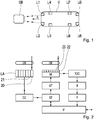
- Fig. 1 shows a vehicle V moving in the direction R.
- the vehicle V has the LiDAR modules Li1 to Li8. These LiDAR modules detect the environment of the vehicle V. Therefore, the object OB is detected by the LiDAR module Li1.
- the LiDAR module Li1 detects the environment of the vehicle V. Therefore, the object OB is detected by the LiDAR module Li1.
- the LiDAR modules Li1 to Li8 have a receiver arrangement according to the invention and a transmitter device which, as described above, has a laser array Transmitted laser pulses to then receive the laser pulses reflected at the object OB with a SPAD array and then evaluated according to the time-correlated photon count to determine the distance between the object OB and the vehicle V.
- the time-of-flight method is used for this.
- Fig. 2 describes in a block diagram an inventive LiDAR module with the receiver arrangement according to the invention.
- the transmitter means comprises a laser array LA with columns or rows 20, 21, etc. As shown above, these columns or rows 20, 21 are individually driven. Thus, a scanning of the surroundings of the vehicle V is achieved.
- An optic OS typically parallelizes the laser beams of the column or row delivered by the laser array LA. However, other configurations for this optic are also possible.
- the laser array LA is driven by a device DC, which accordingly has a driver and a controller for the laser array LA.
- the lasers in the laser array are operated at the desired operating points and caused to emit the laser beams.
- This module DC also outputs a signal to the receiver arrangement and thereby to the controller ST.
- the receiver arrangement there is a so-called front-end RF, which preferably has, for example, the SPAD array, which likewise has columns or rows 22, 23, etc.
- the individual columns or rows are controlled accordingly.
- an optic OE is provided which parallelizes the received light pulses for the individual columns.
- corresponding electrical signals are then generated from the received light pulses by the SPADs. These signals are processed, whereby individual SPADs are combined to form so-called macro-SPADs. This simplifies the signal processing and it is not necessary for each diode SPAD to have its own receiver or its own evaluation circuit.
- the electrical signal is then applied to a time-to-digital conversion TDC to perform the time-correlated photon counting.
- the receiver front-end RF is controlled by a block GT in order to control the corresponding column in the SPAD array.
- the module GT receives this signal from the controller of the receiver circuit ST.
- the controller ST is also connected via the interface IF with the outside world in the vehicle, d. H. It receives signals and also sends signals via this interface IF to other components, for example, to evaluation controllers, etc.
- the time-to-digital conversion TDC performs the distance determination in the manner described above via the time-correlated photon counting in a histogram. This may possibly be buffered in a buffer B or not and is continued in a processing module P, where all necessary calculations are performed in order to determine distance data and the associated quality data from the measured data.
- the data is output for further processing via the interface IF.
- a parameterization of the chipset via the interface IF.
- Fig. 3 shows a part of the circuit of the receiver arrangement according to the invention.
- a photodiode SPAD is shown, which is charged with the bias voltage SPAD.
- the so-called quenching takes place via the quench resistance RQ: the avalanche effect is throttled and ultimately stopped, in the present case by the resistance RQ. Again, this happens in a time that is much less than 1 ns.
- This quenching is necessary to prevent self-destruction of the photodiode. Quenching with a resistor, which is most commonly used, is called passive quenching. There are even more complicated embodiments, which are then called accordingly.
- the electrical output signal of the diode SPAD is supplied to the pulse extender 30.
- This output signal is combined in an OR gate 31 with other output signals 32 of other diodes of the same column.
- a so-called macro diode or a macro receiver is produced. This is also done with other diodes of this column symbolically represented by the OR gate 33. It can be provided even more OR members.
- These OR elements are in turn linked to another OR element 34.
- the total signal is then supplied to the time-to-digital conversion TDA3.
- the TDA3 converts the pulse signals into time signals, which can then be entered into the histogram S. In the histogram S, 130 measurements are then entered per measuring time, as shown above, for example, 2 ms.
- a maximum search determines the time to be allocated for this light pulse. From this, the distance is then determined via P3. This distance can then be sent via the interface IF.
- the time-to-digital conversion TDA3 can be influenced by a block S3, which can also be a software component, in such a way that the clock is lowered. This reduces the temporal resolution and thus distance resolution in the manner described above.
- This memory is saved in the memory S in particular just for the predetermined distances from which this reduction of the resolution should take place.
- the reduction in the block S is performed by the block P3, in which, for example, a bit shift is performed or even samples are combined.
- Fig. 4 shows the flow chart as an example of the inventive method.
- the conversion of the light pulses into the electrical signal takes place, which is then used in method step 401 via the time-correlated photon counting for distance determination.
- the temporal resolution and thus the spatial resolution are reduced if the distance reaches a predetermined value, for example 100 or 150 m or 175 m.
- Fig. 5 shows a situation in which an object OB5 is located at a distance of 300 m from the vehicle V5.
- the vehicle V5 has at the front of the vehicle 2 LiDAR modules Li50 and Li51.
- the object OB5 is now at a distance in which a reduction in the temporal resolution of light pulses, which were emitted by these LiDAR modules Li50 and Li51, takes place. But even at the other distances 100 m, 150 and 200 m, a gradual reduction in the resolution of the distance determination can be done.
- Fig. 6 shows in a table an exemplary assignment of temporal resolution and spatial resolution.
- the column shows the temporal resolution per element in the histogram, which is called the English word Bin.
- the values given above are 125, 250 and 500 ps. This corresponds to a distance resolution in centimeters in the second column of 1.88, 3.75 and corresponding 7.5 cm.
- a resolution of 125 ps per bin in the third column requires 16,000 bins.
- 8,000 and then another only 4,000 This shows the obvious advantages that can be achieved in terms of memory requirements. If one adds the pulse sequence, this increases to the values 17600, 8800 and 4400 as shown in the fourth column.
Landscapes
- Engineering & Computer Science (AREA)
- Physics & Mathematics (AREA)
- Computer Networks & Wireless Communication (AREA)
- General Physics & Mathematics (AREA)
- Radar, Positioning & Navigation (AREA)
- Remote Sensing (AREA)
- Electromagnetism (AREA)
- Optical Radar Systems And Details Thereof (AREA)
Abstract
Description
- Die Erfindung betrifft eine Empfängeranordnung zum Empfang von Lichtimpulsen bzw. ein LiDAR-Modul bzw. ein Verfahren zum Empfangen von Lichtimpulsen nach der Gattung der unabhängigen Patentansprüche.
- Aus
US 9,268,012 B2 - Die erfindungsgemäße Empfängeranordnung zum Empfang von Lichtimpulsen bzw. das LiDAR-Modul bzw. das Verfahren zum Empfang von Lichtimpulsen mit den Merkmalen der unabhängigen Patentansprüche haben demgegenüber den Vorteil, dass eine an den lichtempfindlichen Empfänger angeschlossene Auswerteschaltung aus dem elektrischen Signal, das von dem Empfänger stammt, mittels zeitkorrelierter Photonenzählung mit wenigstens einem Histogramm über eine Flugzeit der Lichtimpulse eine Entfernung zwischen der Empfängeranordnung und wenigstens einem Objekt, das die Lichtimpulse reflektiert, bestimmt. Dabei wird auch ein Startsignal für die Emission der Lichtimpulse verwendet, um den Startzeitpunkt für die Flugzeit zu bekommen. Die Auswerteschaltung wird ab zumindest einer vorbestimmten Entfernung eine Senkung einer Auflösung der Entfernungsbestimmung vornehmen.
- Durch die Verwendung der zeitkorrelierten Photonenzählung ist eine sehr genaue Entfernungsbestimmung möglich, und die Absenkung der Auflösung der Entfernungsbestimmung führt dazu, dass die Anforderung an Speicherplatz für das Histogramm verringert wird und somit geringere Kosten und Aufwand anfallen.
- Die Absenkung der Entfernungsbestimmung bspw. um den Faktor 2 führt zu einer Unsicherheit in wenigen Zentimetern, die ab einer Entfernung bspw. von 100 oder 150 Metern durchaus verkraftbar ist und bspw. keine Nachteile bzgl. der Bestimmung eines Objekts für eine mögliche Kollision darstellt. Die Empfängeranordnung bzw. das LiDAR-Modul bzw. das erfindungsgemäße Verfahren sind insbesondere für die Verwendung in Fahrzeugen gedacht. Die LiDAR-Technik hat sich hier als besonders geeignet erwiesen, um bspw. in Kombination mit anderen Umfeldsensoren wie Videokamera, Radar und/oder Ultraschall eine genaue Objektklassifizierung und Entfernungsbestimmung vorzunehmen.
- Bei der Empfängeranordnung handelt es sich um eine solche, um Lichtimpulse insbesondere Laserimpulse zu empfangen, die von Objekten im Umfeld bspw. eines Fahrzeugs reflektiert wurden. Damit ist dann die Identifikation bzw. Charakterisierung dieser Objekte und insbesondere zumindest eine Entfernungsbestimmung möglich. Die Empfängeranordnung kann als ein Modul eingebaut werden bspw. in ein Fahrzeug. Es kann aber auch sein, dass die Empfängeranordnung aus verschiedenen Teilen besteht, die getrennt ins Fahrzeug eingebaut werden und dann erfindungsgemäß zusammenwirken und entsprechend verbunden werden.
- Bei den Lichtimpulsen handelt es sich, wie bereits erwähnt, üblicherweise um Laserimpulse, die von einer Senderschaltung mit bspw. einem Laserfeld oder Laserarray ausgegeben werden. Damit ist dann insbesondere möglich, die Entfernung über die sogenannte Flugzeit (time of flight) zu bestimmen, weil die Flugzeit der doppelten Entfernung entspricht, die das Licht von der Empfängeranordnung zum Objekt und wieder zurück benötigt. Diese Lichtimpulse üblicherweise Laserimpulse werden vorzugsweise im Infrarotbereich ausgestrahlt. Es ist möglich sie auch im sichtbaren Bereich auszusenden. Entsprechend sind bzgl. des gewünschten Lichts die Emitter also bspw. die Laser und auch die Empfänger also üblicherweise Photodioden auszulegen, so dass die ausgestrahlte Licht auch von den Empfängern empfangen werden kann. Bei den Lasern handelt es sich vorzugsweise um Halbleiterlaser, die aus Verbindungshalbleitern hergestellt werden. Die Laserimpulse werden mit einer bestimmten Frequenz bzw. Periode ausgestrahlt, die eine Messung von 300m entfernten Objekten erzeugt.
- Solch ein lichtempfindlicher Empfänger ist demnach ein Wandler, der die Lichtimpulse in ein elektrisches Signal wandelt. Dabei werden die Photonen des Lichtimpulses von dem Lichtempfänger in einen elektrischen Strom gewandelt. Wie aus den abhängigen Ansprüchen hervorgeht, ist als Empfänger üblicherweise ein Feld von Einzelphotonen-Lawinendioden (SPAD = Single Photon Avalanche Diode) vorgesehen, das vorzugsweise spaltenweise oder zeilenweise in Abhängigkeit von einem Signal einer Senderschaltung aktivierbar ist. D. h. dass in diesem Bespiel ein Laserarray ebenfalls spaltenweise oder zeilenweise angesteuert wird und die entsprechende Spalte oder Zeile im Photodioden-Array also dem Empfänger ausgewählt wird. Damit ist ein Abscannen der Umgebung möglich. Konkret heißt das, dass, wenn die erste Spalte im Laserarray die Lichtimpulse aussendet, dann die erste Spalte oder Zeile im Photodioden-Array derart angesteuert wird, dass nur diese erste Spalte oder Zeile für den Empfang der am Objekt reflektierten Lichtimpulse bereit ist.
- Das elektrische Signal, ein Impuls oder eine Impulsfolge, oder ein anders geartetes Signal, das die Information über die empfangenen Lichtimpulse aufweist, wird einer Auswerteschaltung zugeführt. Nach einer entsprechenden Vorverarbeitung kommt dieses elektrische Signal in eine zeitkorrelierte Photonenzählung mit wenigstens einem Histogramm, um über die Flugzeit der Lichtimpulse eine Entfernung zwischen der Empfängeranordnung und dem wenigstens ein Objekt, das die Lichtimpulse reflektiert, zu bestimmen. In dem Histogramm, wobei es auch mehrere sein können, das in einem Speicher abgelegt ist, werden die Photonen und damit das entsprechende elektrische Signal zu einzelnen Zeiten, die mit der Auswerteschaltung ermittelt werden und dabei insbesondere mit der zeitkorrelierten Photonenzählung, abgelegt. Durch viele Messungen pro Periode, in der ein Lichtimpuls oder ein Paket von Lichtimpulsen abgestrahlt wird, kann dann mit einer Maximumsuche die Zeit ermittelt werden, die am häufigsten vorkommt und die dann als Time-of-flight als Flugzeit verwendet wird. Daraus kann dann in einfacher Art und Weise über die Lichtgeschwindigkeit die Entfernung bestimmt werden.
- Wie aus den abhängigen Ansprüchen hervorgeht, kann für die zeitkorrelierte Photonenzählung mindestens eine Zeit-Digital-Wandlung (Time to Digital Converter) verwendet werden. Mit dieser Schaltung wird also jedem elektrischen Signal eine entsprechende Zeit zugeordnet und diese wird dann im Histogramm abgelegt.
- Diese zeitliche Auflösung ist entsprechend der räumlichen Auflösung. Erfindungsgemäß wurde nun erkannt, dass die räumliche Auflösung für größere Entfernungen reduziert werden kann. Dies liegt daran, dass die Auflösung nur derart gröber wird, dass die Senkung der Auflösung für die Entfernungsbestimmung bei diesen Entfernungen keine Rolle mehr spielt. Bspw. kann damit die Reduktion der Auflösung der Entfernungsbestimmung und damit der zeitlichen Auflösung durch den Faktor 2, die Speicherkosten um die Hälfte reduziert werden. Bspw. ist die typische zeitliche Auflösung für eine Zeit-Digital-Wandlung 125 ps. Verdoppelt man dies, ist die zeitliche Auflösung bei 250 ps.
- Bei der zeitkorrelierten Photonenzählung werden einzelne Photonen der Lichtimpulse detektiert und gezählt und in ein Histogramm eingetragen und zwar an welcher Stelle, in zeitlicher Hinsicht gesehen, das oder die Photonen auftreten. Das Aussenden des Lichtimpulses und die Zählung werden viele Male wiederholt. Dadurch gelingt eine sehr genaue Zeitmessung des Laserimpulses. Bspw. wird ein Objekt von einer Sendeeinrichtung mit vielen Photonen getroffen, die dann durch die Empfängeranordnung empfangen werden. Durch das häufige Wiederholen dieser Photonenbestimmung ist es möglich, den Lichtimpuls bzgl. seiner Flugzeit genau zu bestimmen. Dafür kann bspw. eine Analog-Digital-Wandlung verwendet werden und insbesondere werden die gemessenen Photonenzeiten in ein Histogramm in einem Speicher eingetragen und dann am Ende durch eine Logik wird das Maximum festgestellt. Vorliegend ist eine vorteilhafte Ausgestaltung der Erfindung, einen schnellen Analog-Digital-Wandler mit einer zeitlichen Auflösung von 500MHz bis 2 GHz zu verwenden. Dies kann kostengünstig mit einem sogenannten logarithmischen Flash-Analog-Digital-Wandler verwirklicht werden. Hierbei wird eine Spannung auf eine Serienschaltung von Widerständen gelegt, wobei an den Widerständen Eingänge zu Komparatoren geschaltet sind. Solch eine Serienschaltung wird im Englischen mit voltage ladder bezeichnet.
- Ein Vorteil dieser Methode ist, dass mit der zeitkorrelierten Photonenzählung schwache Empfangssignale von weit entfernten Objekten detektiert werden können. Durch die mehrfache Wiederholung der Messung und Akkumulierung in einem Histogramm kann das Nutzsignal gegenüber dem störenden Umgebungslicht angehoben werden, allerdings ist die Realisierung einer hohen Abtastrate in der Größenordnung 10 GHz derzeit nicht kostengünstig realisierbar.
- Die Auswerteschaltung soll die Auflösung wie oben dargestellt ab mindestens einer vorbestimmten Entfernung absenken. Dies kann gesteuert sein, d. h. es ist bereits vorgegeben, dass es zu gewissen Zeiten für eine gewisse Dauer einfach erfolgt und somit dann kürzere Entfernungen in diesem Zeitabschnitt nicht erkannt werden, oder es ist möglich, dies adaptiv durchzuführen, d. h. durch eine zumindest Abschätzung der Entfernung kann die Auflösung herunter geschaltet werden oder auch dann wieder erhöht werden, wenn sich ein Objekt nähert. Die Auswerteschaltung kann als integrierter Halbleiterbaustein bspw. aus Silizium oder aus verschiedenen Halbleiterbausteinen oder auch in Kombination mit diskreten elektrischen und elektronischen Bausteinen bestehen.
- Bei dem Objekt kann es sich üblicherweise um ein anderes Fahrzeug, einen Fußgänger, ein feststehendes Objekt, wie ein Stein, ein Verkehrszeichen usw. handeln.
- Mit dem Startsignal für die Emission der Lichtimpulse ist ein Signal bezeichnet, dass von einer Senderschaltung, die die Laser für die Emission der Lichtimpulse aufweist, an die Empfängeranordnung übertragen wird und zwar dann, wenn die Emission der Lichtimpulse stattfindet, d.h. der zeitliche Nullpunkt für die Flugzeit der Lichtimpulse ist damit durch dieses Startsignal gekennzeichnet. Dieses Startsignal kann elektrisch ausgeführt sein und demnach über entsprechende Schnittstellen an die Empfängeranordnung übertragen werden. Eine Alternative ist die Nutzung des emittierten Lichts, d.h. das ausgesendete Licht wird auch direkt an die Empfängeranordnung gekoppelt und dort dann in ein elektrisches Startsignal gewandelt. Die Information des Startsignals kann digital oder analog moduliert sein.
- Mit der Senkung der Auflösung der Entfernungsbestimmung ist gemeint, dass wie oben dargestellt die kleinste zeitliche Auflösung erhöht wird, d. h. anstatt wie oben dargestellt 125 ps sind es dann 250 ps. Dies entspricht dann einer Senkung der räumlichen Auflösung, da es sich um die Lichtgeschwindigkeit, mit der die Lichtimpulse sich bewegen, handelt, entsprechen 125 ps einer räumlichen Auflösung von 1,88 cm und 250 ps von 3,75 cm. Verdoppelt man noch einmal die zeitliche Auflösung, also dass nur noch 500 ps aufgelöst werden können, verschlechtert sich die räumliche Auflösung auf 7,5 cm. Insbesondere im Straßenverkehr ist eine Entfernung von 300 m abzudecken. Dies entspricht bei Lichtgeschwindigkeit einer Messzeit von 2000 ns also 2 µs. Das ist die Länge der oben genannten Periode. Die Länge eines Impulses liegt bei 200 ns. In dieser Zeit, den 2µs, können die Messungen im Histogramm abgelegt werden.
- Die Auswerteschaltung kann ein integrierter Schaltkreis aus Silizium sein, sie kann aber auch aus verschiedenen Halbleiterbausteinen, aus diskreten Bauelementen oder Kombinationen daraus bestehen. Teile der Signalverarbeitung können insbesondere auch durch Software, die auf der Auswerteschaltung läuft, erledigt werden.
- Aus den abhängigen Ansprüchen ergeben sich weitere vorteilhafte Ausführungen der in den unabhängigen Patentansprüchen angegebenen Empfängeranordnung bzw. dem LiDAR-Modul bzw. dem Verfahren zum Empfangen von Lichtsignalen.
- Besonders vorteilhaft ist, dass die Auswerteschaltung eine Steuerung aufweist, die für vorbestimmte Zeitabschnitte einen Takt für die Bestimmung der Entfernung aus dem elektrischen Signal senkt. Durch diese Taktabsenkung wird die zeitliche und damit räumliche Auflösung wie oben dargestellt abgesenkt. Diese Steuerung kann bspw. ein Softwarebefehl, ein Signal sein, dass bspw. die Zeit-Digital-Wandlung mit einem halbierten Takt versorgt oder dafür sorgt, dass dieser heruntergeschaltet wird. Dieses Signal kann bspw. von einem anderen Baustein der Auswerteschaltung oder von außerhalb der Auswerteschaltung kommen.
- Weiterhin ist es vorteilhaft, dass die Auswerteschaltung wenigstens einen Zeit-Digital-Wandler für zeitkorrelierte Photonenzählung aufweist, wobei die Steuerung den Takt des wenigstens ein Zeit-Digital-Wandler senkt. Eine Zeit-Digital-Wandlung ist ein Verfahren, um eine Zeit beispielsweise zwischen zwei Impulsen zu bestimmen und in ein Digitalwort umzusetzen. Dazu kann bspw. ein Zähler verwendet werden, der durch ein Start- und ein Stoppsignal bspw. des empfangenen Lichtimpulses bzw. des ausgesendeten Lichtimpulses aktiviert wird. Um den Fehler zu Beginn und zu Ende des durch den Zähler ermittelten Zählerstandes zu bestimmen, wird eine sogenannte Interpolation verwendet. Dazu kann eine Verzögerungsschaltung verwendet werden. Es ist jedoch auch möglich, zwei zueinander verstimmte Oszillatoren zu verwenden oder eine sogenannte Überabtastung bspw. eine Vierfach-Überabtastung zu verwenden und damit das Signal abzutasten. Durch den Zählerstand und die Werte, die aus der Interpolation gewonnen werden zu Beginn der Zählung und zu Ende der Zählung, kann dann die Zeit und damit die Flugzeit genau gemessen werden.
- Der Vorteil dieser Methode besteht in der hohen zeitlichen Auflösung von ca. 100 ps. Dies entspricht einer Abtastrate von 10 GHz oder einer Distanzmessgenauigkeit von 1,5 cm.
- Alternativ ist es möglich, dass der wenigstens eine Zeit-Digital-Wandler seinen Takt behält und dass dann andere unten beschriebene Methoden verwendet werden, um die Auflösung zu senken.
- Darüber hinaus ist es vorteilhaft, dass die Auswerteschaltung eine Abtastung aufweist, die aus dem elektrischen Signal Abtastwerte erzeugt, wobei die Auswerteschaltung eine Signalverarbeitung für die Abtastwerte aufweist, die die Abtastwerte zusammenfasst, um die Senkung der Auflösung der Entfernungsbestimmung zu erreichen. Demnach ist es möglich, das elektrische Signal zu digitalisieren oder zumindest entsprechende Impulse, die vorliegend Abtastwerte darstellen, zu erzeugen, wobei diese Abtastwerte dann zusammengefasst werden, was einer Absenkung der Auflösung der Entfernungsbestimmung entspricht, da dann nicht mehr diese beiden Abtastwerte aufgelöst werden können. Wie dargestellt können sowohl die Auswerteschaltung, die Signalverarbeitung und andere Komponenten softwaretechnisch und/oder hardwaretechnisch realisiert sein.
- Weiterhin ist es vorteilhaft, dass die Auswerteschaltung wenigstens einen Speicher für das wenigstens eine Histogramm aufweist, der für die Senkung der Auflösung der Entfernungsbestimmung wenigstens einen Bitshift vornimmt. Durch einen Bitshift können bspw. die niederwertigsten Abtastwerte eliminiert werden, um damit eine Senkung der Auflösung der Entfernungsbestimmung zu erreichen. Bspw. wird in entsprechender Indexadresse in dem Speicher das unterste, mithin niederwertigste Bit verworfen, die binären Adressen in dem Histogrammspeicher werden bei jeder Stufe um ein Bit nach rechts geshiftet. Bspw. wird bei einer Entfernung von 0 bis 75 m kein Shift vorgenommen, also ein Shift um 0 Bit, bei 75 bis 150 m Entfernung ein Shift um 1 Bit und bei 150 bis 300 m Entfernung ein Shift um 2 Bit. Damit wird eine Absenkung der Auflösung erreicht. Dieser Speicher kann nur für das Histogramm vorgesehen sein, es kann jedoch auch ein Teil eines Halbleiterspeichers für das Histogramm verwendet werden. Dies kann statisch oder dynamisch sein.
- Es ist vorteilhaft, dass die Auswerteschaltung pro Lichtimpuls 100 bis 150 vorzugsweise 130 Messungen im Histogramm ablegt. Wie oben dargestellt, wird vorliegend beispielhaft von einer Messzeit von 2000 ns ausgegangen, wenn man eine Maximalentfernung für die Entfernungsbestimmung von 300 m annimmt. Dann werden bspw. pro Lichtimpuls 100 bis 150 und vorzugsweise 130 Messungen im Histogramm abgelegt, um die Entfernung des Objekts über die Flugzeit zu bestimmen.
- Es ist vorteilhaft, dass der Empfänger ein Feld aus Einzelphotonen-Lawinendioden (SPAD = Single Photon Avalanche Diode) aufweist, das spaltenweise oder zeilenweise in Abhängigkeit von einem Signal einer Senderschaltung aktivierbar ist. Vorliegend wird davon ausgegangen, dass ein Abscannen der Umgebung, also ein Abtasten der Umgebung, um ein Fahrzeug durch eine spaltenweise oder zeilenweise Ansteuerung von Lasern in einem Laserarray erreicht wird und entsprechend eine spaltenweise oder zeilenweise Ansteuerung oder Aktivierung der SPADs in deren Array erfolgt. D.h. wird die erste Spalte im Laserarray aktiviert, wird auch die erste Spalte im SPAD-Array aktiviert. Vorteilhafterweise kennzeichnet dieses der Senderschaltung das Versenden des Lichtimpulses. Damit wird eine Synchronisierung der Aktivierung der Spalte der SPAD erreicht. Zu beachten ist, dass bspw. eine Rauschschwelle vorgesehen ist, damit Umgebungslicht oder Streulicht, das nicht von den Lichtimpulsen stammt, ausgefiltert wird. Damit sind letztlich mehr als ein Photon notwendig, um ein elektrisches Signal zu erzeugen, das erfindungsgemäß in der Auswerteschaltung weiterverarbeitet wird. Die Rauschschwelle ist elektronisch vorgesehen.
- In der nachfolgenden Beschreibung werden Ausführungsbeispiele der Erfindung dargestellt und durch die Figuren anhand von Ausführungsbeispielen erläutert.
- Es zeigen:
-
Fig. 1 eine beispielhafte Konfiguration von LiDAR-Modulen in einem Fahrzeug, -
Fig. 2 eine Darstellung als Blockschaltbild eines LiDAR-Moduls mit der erfindungsgemäßen Empfängerschaltung, -
Fig. 3 einen Schaltungsausschnitt der erfindungsgemäßen Empfängerschaltung und -
Fig. 4 ein Flussdiagramm des erfindungsgemäßen Verfahrens, -
Fig. 5 eine Darstellung des Objekts und mit verschiedenen Entfernungen im Vergleich zum Fahrzeug und -
Fig. 6 eine Tabelle, die die Zuordnung der zeitlichen und räumlichen Auflösung für das Histogramm darstellt. -
Fig. 1 zeigt ein Fahrzeug V, das sich in die Richtung R bewegt. Das Fahrzeug V weist die LiDAR-Module Li1 bis Li8 auf. Diese LiDAR-Module erfassen die Umgebung des Fahrzeugs V. Daher wird das Objekt OB durch das LiDAR-Modul Li1 erfasst. Durch eine Entfernungsbestimmung und entsprechende Charakterisierung anhand der Bewegungsparameter des Objekts ist es möglich, auf eine mögliche Kollision zu schließen und entsprechende Bewegungen des Fahrzeugs V zu beeinflussen, um nicht mit dem Objekt OB zu kollidieren. - Die LiDAR-Module Li1 bis Li8 weisen eine erfindungsgemäße Empfängeranordnung auf und eine Sendereinrichtung, die wie oben beschrieben mit einem Laserarray die Laserimpulse versendet, um die am Objekt OB reflektierten Laserimpulse dann mit einem SPAD-Array zu empfangen und dann entsprechend mit der zeitkorrelierten Photonenzählung auszuwerten, um die Entfernung zwischen dem Objekt OB und dem Fahrzeug V zu bestimmen. Dafür wird die Time-of-Flight-Methode verwendet.
-
Fig. 2 beschreibt in einem Blockschaltbild ein erfindungsgemäßes LiDAR-Modul mit der erfindungsgemäßen Empfängeranordnung. Die Sendereinrichtung weist ein Laserarray LA auf mit Spalten oder Zeilen 20, 21 usw. Wie oben dargestellt, werden diese Spalten oder Zeilen 20, 21 einzeln angesteuert. Damit wird ein Abtasten der Umgebung des Fahrzeugs V erreicht. Eine Optik OS parallelisiert üblicherweise die von dem Laserarray LA abgegebenen Laserstrahlen der Spalte oder der Zeile vorliegend 20. Es sind jedoch auch andere Konfigurationen für diese Optik möglich. - Das Laserarray LA wird durch einen Baustein DC angetrieben, der entsprechend einen Treiber und eine Steuerung für das Laserarray LA aufweist. Damit werden die Laser im Laserarray in den gewünschten Betriebspunkten betrieben und zur Emission der Laserstrahlen veranlasst.
- Dieser Baustein DC gibt auch ein Signal an die Empfängeranordnung ab und dabei an die Steuerung ST. In der Empfängeranordnung liegt ein sogenanntes Front-End RF vor, das vorzugsweise beispielhaft das SPAD-Array aufweist, das ebenfalls Spalten oder Zeilen 22, 23 usw. aufweist. Hier werden entsprechend die einzelnen Spalten oder Zeilen angesteuert. Dargestellt ist hier, da die erste Spalte oder Zeile im Laserarray LA 20 angesteuert wurde, dass hier nun auch die erste Spalte oder Zeile 22 des SPAD-Arrays angesteuert wird. Auch hier ist eine Optik OE vorgesehen, die die empfangenen Lichtimpulse für die einzelnen Spalten parallelisiert. Im Empfänger-Front-End RF werden dann aus den empfangenen Lichtimpulsen durch die SPADs entsprechende elektrische Signale erzeugt. Diese Signale werden aufbereitet, wobei dabei einzelne SPADs zu sogenannten Makro-SPADs zusammengefasst werden. Damit wird die Signalverarbeitung vereinfacht und es muss nicht für jede Diode SPAD ein eigener Empfänger bzw. eine eigene Auswerteschaltung vorgesehen sein.
- Das elektrische Signal wird danach einer Zeit-Digital-Wandlung TDC zugeführt, um die zeitkorrelierte Photonenzählung durchzuführen. Das Empfänger-Front-end RF wird von einem Baustein GT angesteuert, um die entsprechende Spalte im SPAD-Array anzusteuern. Der Baustein GT erhält dieses Signal von der Steuerung der Empfängerschaltung ST. Die Steuerung ST ist auch über die Schnittstelle IF mit der Außenwelt im Fahrzeug verbunden, d. h. es empfängt Signale und sendet auch Signale über diese Schnittstelle IF zu anderen Komponenten bspw. zu Auswertesteuergeräten usw.
- Die Zeit-Digital-Wandlung TDC führt in der oben beschriebenen Weise über die zeitkorrelierte Photonenzählung in einem Histogramm die Entfernungsbestimmung durch. Dies kann evtl. in einem Buffer B zwischengespeichert werden oder auch nicht und wird in einem Verarbeitungsbaustein P weitergeführt, wo alle notwendigen Berechnungen durchgeführt werden, um aus den gemessenen Daten Entfernungsdaten und die dazugehörigen Qualitätsdaten zu ermitteln. Über das Interface IF werden die Daten zur weiteren Verarbeitung ausgegeben. Außerdem erfolgt eine Parametrierung des Chipsatzes über das Interface IF.
-
Fig. 3 zeigt einen Teil der Schaltung der erfindungsgemäßen Empfängeranordnung. Beispielhaft ist hier lediglich eine Photodiode SPAD dargestellt, die entsprechend mit der Vorspannung SPAD beaufschlagt wird. Über den Quenchwiderstand RQ erfolgt das sogenannte Quenching: Der Lawineneffekt wird gedrosselt und letztlich gestoppt, vorliegend durch den Widerstand RQ. Auch dies geschieht in einer Zeit, die sehr viel kleiner als 1 ns ist. Dieses Quenchen ist notwendig, um die Selbstzerstörung der Photodiode zu verhindern. Das Quenchen mit einem Widerstand, was am häufigsten verwendet wird, wird als passives Quenchen bezeichnet. Es gibt noch kompliziertere Ausgestaltungen, die dann entsprechend genannt werden. - Das elektrische Ausgangssignal der Diode SPAD wird dem Impulsverlängerer 30 zugeführt. Dieses Ausgangssignal wird in einem OR-Glied 31 mit anderen Ausgangssignalen 32 anderer Dioden der gleichen Spalte verknüpft. Damit wird eine sogenannte Makrodiode oder ein Makroempfänger hergestellt. Dies geschieht auch mit anderen Dioden dieser Spalte symbolisch dargestellt durch das OR-Glied 33. Es können noch weitere OR-Glieder vorgesehen sein. Diese OR-glieder werden wiederum mit einem weiteren OR-Glied 34 verknüpft. Das Gesamtsignal wird dann der Zeit-Digital-Wandlung TDA3 zugeführt. Die TDA3 wandelt die Impulssignale in Zeitsignale um, die dann ins Histogramm S eingetragen werden können. Im Histogramm S werden dann pro Messzeit, wie oben dargestellt bspw. 2 ms 130 Messungen eingetragen. Durch eine Maximumsuche wird die Zeit festgestellt, die für diesen Lichtimpuls zuzuordnen ist. Daraus wird dann über P3 die Entfernung bestimmt. Diese Entfernung kann dann über die Schnittstelle IF versendet werden. Die Zeit-Digital-Wandlung TDA3 kann durch einen Baustein S3, der auch ein Softwarebaustein sein kann, derart beeinflusst, dass der Takt abgesenkt wird. Dies senkt die zeitliche Auflösung und damit Entfernungsauflösung in der oben beschriebenen Weise. Damit wird Speicher im Speicher S eingespart insbesondere eben für die vorbestimmten Entfernungen, ab denen diese Senkung der Auflösung stattfinden soll. Alternativ ist es möglich, dass die Senkung im Baustein S durch den Baustein P3 durchgeführt wird, in dem bspw. ein Bitshift durchgeführt wird oder eben auch Abtastwerte zusammengefasst werden.
-
Fig. 4 zeigt das Flussdiagramm als Beispiel für das erfindungsgemäße Verfahren. In Verfahrensschritt 400 erfolgt die Wandlung der Lichtimpulse in das elektrische Signal, das dann in Verfahrensschritt 401 über die zeitkorrelierte Photonenzählung zur Entfernungsbestimmung verwendet wird. In Verfahrensschritt 402 erfolgt eine Absenkung der zeitlichen Auflösung und damit der räumlichen Auflösung, wenn die Entfernung einen vorbestimmten Wert bspw. 100 oder 150 m oder 175 m erreicht. -
Fig. 5 zeigt eine Situation, in der sich ein Objekt OB5 in einer Entfernung von 300 m vom Fahrzeug V5 aufhält. Das Fahrzeug V5 hat an der Fahrzeugfront 2 LiDAR-Module Li50 und Li51. Das Objekt OB5 ist nun in einer Entfernung in der eine Absenkung der zeitlichen Auflösung von Lichtimpulsen, die von diesen LiDAR-Modulen Li50 und Li51 ausgesendet wurden, erfolgt. Aber auch bei den anderen Entfernungen 100 m, 150 und 200 m kann eine schrittweise Senkung der Auflösung der Entfernungsbestimmung erfolgen. -
Fig. 6 zeigt in einer Tabelle eine bespielhafte Zuordnung von zeitlicher Auflösung und räumlicher Auflösung. In der Spalte ist die zeitliche Auflösung pro Element im Histogramm, das mit dem englischen Wort Bin bezeichnet wird, dargestellt. Es sind die Werte von oben 125, 250 und 500 ps angegeben. Dies entspricht einer Entfernungsauflösung in Zentimetern in der zweiten Spalte von 1,88, 3,75 und entsprechend 7,5 cm. Für den gesamten Messabschnitt werden bei einer Auflösung pro Bin von 125 ps in der dritten Spalte 16000 Bins benötigt. Entsprechend bei einer Halbierung dann nur noch 8000 und einer weiteren dann nur noch 4000. Dies zeigt die offensichtlichen Vorteile, die in Bezug auf den Speicherbedarf erreicht werden können. Nimmt man noch die Impulsfolge hinzu erhöht sich dies wie in der vierten Spalte dargestellt auf die Werte 17600, 8800 und 4400. -
- V, V5
- Fahrzeug
- R
- Richtung
- Li1-8
- LiDAR-Module
- OB, OB5
- Objekt
- LA
- Laserarray
- 20, 21
- Spalten des Laserarray
- OS
- Optik
- DC
- Baustein
- ST
- Steuerung
- RF
- Front-End
- 22, 23
- Spalten des SPAD-Array
- OE
- Optik
- TDC
- Zeit-Digitalwandlung
- GT
- Baustein
- IF
- Schnittstelle
- P
- Verarbeitungsbaustein
- RQ
- Quenchwiderstand
- 30
- Impulsverlängerer
- 31, 33, 34
- OR-Glied
- 32
- Ausgangssignale
- TDA3
- Zeit-Digitalwandlung
- S
- Speicher für das Histogramm
- P3
- Auswertung
- S3
- Baustein
- 400, 401, 402
- Verfahrensschritte
- Li50, 51
- LiDAR-Module
Claims (9)
- Empfängeranordnung zum Empfang von Lichtimpulsen mit:- wenigstens einem lichtempfindlichen Empfänger (SPAD), der die Lichtimpulse in ein elektrisches Signal wandelt.- einer an den Empfänger angeschlossenen Auswerteschaltung, die aus dem elektrischen Signal mittels zeitkorrelierter Photonenzählung mit wenigstens einem Histogramm über eine Flugzeit der Lichtimpulse und in Abhängigkeit von einem Startsignal für die Lichtimpulse eine Entfernung zwischen der Empfängeranordnung und dem wenigstens einem Objekt, das die Lichtimpulse reflektiert, bestimmt, wobei die Auswerteschaltung derart konfiguriert ist, dass die Auswerteschaltung ab zumindest einer vorbestimmten Entfernung eine Senkung einer Auflösung der Entfernungsbestimmung vornimmt.
- Empfängeranordnung nach Anspruch 1, dadurch gekennzeichnet, dass die Auswerteschaltung eine Steuerung (ST) aufweist, die für vorbestimmte Zeitabschnitte einen Takt für die Bestimmung der Entfernung aus dem elektrischen Signal senkt.
- Empfängeranordnung nach Anspruch 2, dadurch gekennzeichnet, dass die Auswerteschaltung wenigstens einen Zeit-Digital-Wandler für die zeitkorrelierte Photonenzählung aufweist, wobei die Steuerung (ST) den Takt des wenigstens ein Zeit-Digital-Wandlers (TDC) senkt.
- Empfängeranordnung nach Anspruch 1 dadurch gekennzeichnet, dass die Auswerteschaltung eine Abtastung aufweist, die aus dem elektrischen Signal Abtastwerte erzeugt, wobei die Auswerteschaltung eine Signalverarbeitung für die Abtastwerte aufweist, die Abtastwerte zusammenfasst, um die Senkung der Auflösung der Entfernungsbestimmung zu erreichen.
- Empfängeranordnung nach Anspruch 1 dadurch gekennzeichnet, dass die Auswerteschaltung einen Speicher (S) für das wenigstens eine Histogramm aufweist, der für die Senkung der Auflösung der Entfernungsbestimmung wenigstens einen Bitshift vornimmt.
- Empfängeranordnung nach einem der vorhergehenden Ansprüche, dadurch gekennzeichnet, dass die Auswerteschaltung pro Lichtimpuls 100 bis 150 vorzugsweise 130 Messungen im Histogramm ablegt.
- Empfängeranordnung nach einem der vorhergehenden Ansprüche, dadurch gekennzeichnet, dass der Empfänger ein Feld von Einzelphotonen Lawinendioden (SPAD) aufweist, das spaltenweise oder zeilenweise in Abhängigkeit von dem Signal aktivierbar ist.
- LiDAR-Modul mit einer Empfängeranordnung nach einem der Ansprüche 1 bis 7 und einer Senderschaltung, die ein Laserarray aufweist, wobei das Laserarray spaltenweise oder zeilenweise aktivierbar ist und das Startsignal die Emission der Lichtimpulse durch eine Spalte oder eine Zeile kennzeichnet, wobei durch das Signal die entsprechende Spalte oder Zeile im Feld des Empfängers aktiviert ist.
- Verfahren zum Empfangen von Lichtimpulsen in folgenden Schritten:- Wandeln der Lichtimpulse in ein elektrisches Signal durch einen lichtempfindlichen Empfänger (SPAD).- Bestimmen einer Entfernung zwischen einer Empfängerschaltung und wenigstens einem Objekt (OB), das die Lichtimpulse reflektiert, aus dem elektrischen Signal durch eine zeitkorrelierte Photonenzählung mit wenigstens einem Histogramm über eine Flugzeit der Lichtimpulse und in Abhängigkeit von einem Startsignal für eine Emission der Lichtimpulse.- Vornehmen einer Absenkung einer Auflösung der Entfernungsbestimmung ab zumindest einer vorbestimmten Entfernung.
Applications Claiming Priority (1)
| Application Number | Priority Date | Filing Date | Title |
|---|---|---|---|
| DE102018203534.2A DE102018203534A1 (de) | 2018-03-08 | 2018-03-08 | Empfängeranordnung zum Empfang von Lichtimpulsen, LiDAR-Modul und Verfahren zum Empfangen von Lichtimpulsen |
Publications (2)
| Publication Number | Publication Date |
|---|---|
| EP3537180A1 true EP3537180A1 (de) | 2019-09-11 |
| EP3537180B1 EP3537180B1 (de) | 2021-12-15 |
Family
ID=65408973
Family Applications (1)
| Application Number | Title | Priority Date | Filing Date |
|---|---|---|---|
| EP19156472.3A Not-in-force EP3537180B1 (de) | 2018-03-08 | 2019-02-11 | Empfängeranordnung zum empfang von lichtimpulsen, lidar-modul und verfahren zum empfangen von lichtimpulsen |
Country Status (4)
| Country | Link |
|---|---|
| US (1) | US11598856B2 (de) |
| EP (1) | EP3537180B1 (de) |
| CN (1) | CN110244316B (de) |
| DE (1) | DE102018203534A1 (de) |
Cited By (1)
| Publication number | Priority date | Publication date | Assignee | Title |
|---|---|---|---|---|
| US20230184901A1 (en) * | 2020-08-25 | 2023-06-15 | Hesai Technology Co., Ltd. | Laser emitting unit for lidar and lidar |
Families Citing this family (74)
| Publication number | Priority date | Publication date | Assignee | Title |
|---|---|---|---|---|
| US11609336B1 (en) | 2018-08-21 | 2023-03-21 | Innovusion, Inc. | Refraction compensation for use in LiDAR systems |
| US10620300B2 (en) | 2015-08-20 | 2020-04-14 | Apple Inc. | SPAD array with gated histogram construction |
| US11300683B2 (en) | 2016-12-30 | 2022-04-12 | Innovusion Ireland Limited | Multiwavelength LiDAR design |
| US10942257B2 (en) | 2016-12-31 | 2021-03-09 | Innovusion Ireland Limited | 2D scanning high precision LiDAR using combination of rotating concave mirror and beam steering devices |
| US11009605B2 (en) | 2017-01-05 | 2021-05-18 | Innovusion Ireland Limited | MEMS beam steering and fisheye receiving lens for LiDAR system |
| US11054508B2 (en) | 2017-01-05 | 2021-07-06 | Innovusion Ireland Limited | High resolution LiDAR using high frequency pulse firing |
| US10969475B2 (en) | 2017-01-05 | 2021-04-06 | Innovusion Ireland Limited | Method and system for encoding and decoding LiDAR |
| US10830879B2 (en) | 2017-06-29 | 2020-11-10 | Apple Inc. | Time-of-flight depth mapping with parallax compensation |
| WO2019079642A1 (en) | 2017-10-19 | 2019-04-25 | Innovusion Ireland Limited | LIDAR WITH EXTENDED DYNAMIC RANGE |
| KR102403544B1 (ko) | 2017-12-18 | 2022-05-30 | 애플 인크. | 방출기들의 어드레스가능 어레이를 사용하는 비행 시간 감지 |
| US11493601B2 (en) | 2017-12-22 | 2022-11-08 | Innovusion, Inc. | High density LIDAR scanning |
| WO2019139895A1 (en) | 2018-01-09 | 2019-07-18 | Innovusion Ireland Limited | Lidar detection systems and methods that use multi-plane mirrors |
| US11675050B2 (en) | 2018-01-09 | 2023-06-13 | Innovusion, Inc. | LiDAR detection systems and methods |
| WO2019165130A1 (en) | 2018-02-21 | 2019-08-29 | Innovusion Ireland Limited | Lidar detection systems and methods with high repetition rate to observe far objects |
| US11927696B2 (en) | 2018-02-21 | 2024-03-12 | Innovusion, Inc. | LiDAR systems with fiber optic coupling |
| WO2019165289A1 (en) | 2018-02-22 | 2019-08-29 | Innovusion Ireland Limited | Receive path for lidar system |
| WO2020013890A2 (en) | 2018-02-23 | 2020-01-16 | Innovusion Ireland Limited | Multi-wavelength pulse steering in lidar systems |
| WO2019165095A1 (en) | 2018-02-23 | 2019-08-29 | Innovusion Ireland Limited | Distributed lidar systems |
| CN112292608B (zh) | 2018-02-23 | 2024-09-20 | 图达通智能美国有限公司 | 用于lidar系统的二维操纵系统 |
| US11567182B2 (en) | 2018-03-09 | 2023-01-31 | Innovusion, Inc. | LiDAR safety systems and methods |
| WO2019199796A1 (en) | 2018-04-09 | 2019-10-17 | Innovusion Ireland Limited | Compensation circuitry for lidar receiver systems and method of use thereof |
| US11289873B2 (en) | 2018-04-09 | 2022-03-29 | Innovusion Ireland Limited | LiDAR systems and methods for exercising precise control of a fiber laser |
| DE102018208647B4 (de) | 2018-05-30 | 2025-08-14 | Fraunhofer-Gesellschaft zur Förderung der angewandten Forschung e.V. | Lasermesseinrichtung zur Messung einer Distanz zu einem Objekt sowie Verfahren zum Betreiben derselben |
| CN112585492B (zh) | 2018-06-15 | 2024-10-25 | 图达通智能美国有限公司 | 用于聚焦感兴趣的范围的lidar系统和方法 |
| US11860316B1 (en) | 2018-08-21 | 2024-01-02 | Innovusion, Inc. | Systems and method for debris and water obfuscation compensation for use in LiDAR systems |
| US11579300B1 (en) | 2018-08-21 | 2023-02-14 | Innovusion, Inc. | Dual lens receive path for LiDAR system |
| US11614526B1 (en) | 2018-08-24 | 2023-03-28 | Innovusion, Inc. | Virtual windows for LIDAR safety systems and methods |
| US11796645B1 (en) | 2018-08-24 | 2023-10-24 | Innovusion, Inc. | Systems and methods for tuning filters for use in lidar systems |
| US11579258B1 (en) | 2018-08-30 | 2023-02-14 | Innovusion, Inc. | Solid state pulse steering in lidar systems |
| US12313788B1 (en) | 2018-10-09 | 2025-05-27 | Seyond, Inc. | Ultrashort pulses in LiDAR systems |
| CN114114606B (zh) | 2018-11-14 | 2024-09-06 | 图达通智能美国有限公司 | 使用多面镜的lidar系统和方法 |
| DE112020000407B4 (de) | 2019-01-10 | 2024-02-15 | Innovusion, Inc. | Lidar-systeme und -verfahren mit strahllenkung und weitwinkelsignaldetektion |
| US11486970B1 (en) | 2019-02-11 | 2022-11-01 | Innovusion, Inc. | Multiple beam generation from a single source beam for use with a LiDAR system |
| WO2020167338A1 (en) | 2019-02-11 | 2020-08-20 | Apple Inc. | Depth sensing using a sparse array of pulsed beams |
| US11733384B2 (en) * | 2019-02-20 | 2023-08-22 | Samsung Electronics Co., Ltd. | Single pass peak detection in LIDAR sensor data stream |
| US11977185B1 (en) | 2019-04-04 | 2024-05-07 | Seyond, Inc. | Variable angle polygon for use with a LiDAR system |
| US11500094B2 (en) | 2019-06-10 | 2022-11-15 | Apple Inc. | Selection of pulse repetition intervals for sensing time of flight |
| US11555900B1 (en) | 2019-07-17 | 2023-01-17 | Apple Inc. | LiDAR system with enhanced area coverage |
| CN110596723B (zh) * | 2019-09-19 | 2023-03-14 | 深圳奥锐达科技有限公司 | 动态直方图绘制飞行时间距离测量方法及测量系统 |
| CN110596724B (zh) * | 2019-09-19 | 2022-07-29 | 深圳奥锐达科技有限公司 | 动态直方图绘制飞行时间距离测量方法及测量系统 |
| CN110596722B (zh) * | 2019-09-19 | 2022-10-04 | 深圳奥锐达科技有限公司 | 直方图可调的飞行时间距离测量系统及测量方法 |
| CN110596721B (zh) * | 2019-09-19 | 2022-06-14 | 深圳奥锐达科技有限公司 | 双重共享tdc电路的飞行时间距离测量系统及测量方法 |
| DE102019127667A1 (de) * | 2019-10-15 | 2021-04-15 | Sick Ag | Entfernungsmessender optoelektronischer Sensor und Verfahren zur Erfassung eines Zielobjekts |
| CN110780312B (zh) * | 2019-10-15 | 2022-10-21 | 深圳奥锐达科技有限公司 | 一种可调距离测量系统及方法 |
| US11733359B2 (en) * | 2019-12-03 | 2023-08-22 | Apple Inc. | Configurable array of single-photon detectors |
| US12123980B2 (en) * | 2020-01-21 | 2024-10-22 | Semiconductor Components Industries, Llc | LIDAR system with dynamic resolution |
| DE102020201637A1 (de) * | 2020-02-11 | 2021-08-12 | Ibeo Automotive Systems GmbH | Verfahren zur Analyse von Rückstreuungs-Histogrammdaten bei einem optischen Pulslaufzeit-Verfahren und Vorrichtung zur Datenverarbeitung |
| EP4115198A4 (de) * | 2020-03-05 | 2024-03-20 | Opsys Tech Ltd. | Rauschfilterungssystem und verfahren für festkörper-lidar |
| US11644553B2 (en) | 2020-04-17 | 2023-05-09 | Samsung Electronics Co., Ltd. | Detection of reflected light pulses in the presence of ambient light |
| CN111562590A (zh) * | 2020-05-22 | 2020-08-21 | 深圳市灵明光子科技有限公司 | 一种多梯度时间箱的测距方法及测距系统 |
| CN112147626A (zh) * | 2020-09-14 | 2020-12-29 | Oppo广东移动通信有限公司 | 电子装置、电子装置的控制方法、及计算机可读存储介质 |
| CN112558097A (zh) * | 2020-11-23 | 2021-03-26 | Oppo(重庆)智能科技有限公司 | 电子装置、电子装置的控制方法、及计算机可读存储介质 |
| US20240027616A1 (en) * | 2020-11-27 | 2024-01-25 | Ningbo ABAX Sensing Electronic Technology Co., Ltd. | Distance information acquisition system |
| JP7596810B2 (ja) * | 2021-01-22 | 2024-12-10 | Toppanホールディングス株式会社 | 距離画像撮像装置及び距離画像撮像方法 |
| US12442926B2 (en) | 2021-02-04 | 2025-10-14 | Apple Inc. | Time-of-flight depth sensing with improved linearity |
| US12061289B2 (en) | 2021-02-16 | 2024-08-13 | Innovusion, Inc. | Attaching a glass mirror to a rotating metal motor frame |
| US11422267B1 (en) | 2021-02-18 | 2022-08-23 | Innovusion, Inc. | Dual shaft axial flux motor for optical scanners |
| EP4260086B1 (de) | 2021-03-01 | 2024-11-27 | Seyond, Inc. | Faserbasierte sende- und empfangskanäle von lidar-systemen |
| US12196860B2 (en) | 2021-03-02 | 2025-01-14 | Apple Inc. | Depth sensor calibration using internal reflections |
| US11555895B2 (en) | 2021-04-20 | 2023-01-17 | Innovusion, Inc. | Dynamic compensation to polygon and motor tolerance using galvo control profile |
| US11614521B2 (en) | 2021-04-21 | 2023-03-28 | Innovusion, Inc. | LiDAR scanner with pivot prism and mirror |
| WO2022225859A1 (en) | 2021-04-22 | 2022-10-27 | Innovusion, Inc. | A compact lidar design with high resolution and ultra-wide field of view |
| US11662439B2 (en) | 2021-04-22 | 2023-05-30 | Innovusion, Inc. | Compact LiDAR design with high resolution and ultra-wide field of view |
| EP4314885A1 (de) | 2021-05-12 | 2024-02-07 | Innovusion, Inc. | Systeme und vorrichtungen zur minderung von lidar-rauschen, -vibration und -schärfe |
| CN117413199A (zh) | 2021-05-21 | 2024-01-16 | 图达通智能美国有限公司 | 使用lidar扫描仪内部的检流计镜进行智能扫描的移动配置文件 |
| US11768294B2 (en) | 2021-07-09 | 2023-09-26 | Innovusion, Inc. | Compact lidar systems for vehicle contour fitting |
| US11681028B2 (en) | 2021-07-18 | 2023-06-20 | Apple Inc. | Close-range measurement of time of flight using parallax shift |
| CN113608230A (zh) * | 2021-08-03 | 2021-11-05 | 汤恩智能科技(常熟)有限公司 | 测距方法、装置及设备 |
| US12468017B2 (en) | 2021-10-15 | 2025-11-11 | Seyond, Inc. | Integrated mirror motor galvanometer |
| CN216356147U (zh) | 2021-11-24 | 2022-04-19 | 图达通智能科技(苏州)有限公司 | 一种车载激光雷达电机、车载激光雷达及车辆 |
| US11871130B2 (en) | 2022-03-25 | 2024-01-09 | Innovusion, Inc. | Compact perception device |
| US12204033B2 (en) | 2022-03-25 | 2025-01-21 | Seyond, Inc. | Multimodal detection with integrated sensors |
| DE102023108881A1 (de) | 2023-04-06 | 2024-10-10 | Valeo Detection Systems GmbH | Optische empfangseinheit für ein lidar-system, lidar-system für ein fahrzeug sowie verfahren zu betreiben eines lidar-systems |
| WO2025133038A1 (en) * | 2023-12-22 | 2025-06-26 | Valeo Vision | Visible light sensing system for vehicle, vehicle comprising the system and method for deployment of said system in a vehicle |
Citations (3)
| Publication number | Priority date | Publication date | Assignee | Title |
|---|---|---|---|---|
| US20170052065A1 (en) * | 2015-08-20 | 2017-02-23 | Apple Inc. | SPAD array with gated histogram construction |
| WO2018122560A1 (en) * | 2016-12-30 | 2018-07-05 | The University Court Of The University Of Edinburgh | Photon sensor apparatus |
| WO2018140522A2 (en) * | 2017-01-25 | 2018-08-02 | Apple Inc. | Spad detector having modulated sensitivity |
Family Cites Families (14)
| Publication number | Priority date | Publication date | Assignee | Title |
|---|---|---|---|---|
| DE102010061382B4 (de) * | 2010-12-21 | 2019-02-14 | Sick Ag | Optoelektronischer Sensor und Verfahren zur Erfassung und Abstandsbestimmung von Objekten |
| WO2013066959A1 (en) * | 2011-10-31 | 2013-05-10 | The Trustees Of Columbia University In The City Of New York | Systems and methods for imaging using single photon avalanche diodes |
| EP2589980A1 (de) * | 2011-11-04 | 2013-05-08 | Leica Geosystems AG | Entfernungsmesser |
| CN103218776B (zh) * | 2013-03-07 | 2016-06-22 | 天津大学 | 基于最小生成树的非局部的深度图超分辨率重建方法 |
| US9268012B2 (en) | 2013-07-12 | 2016-02-23 | Princeton Optronics Inc. | 2-D planar VCSEL source for 3-D imaging |
| US10288736B2 (en) * | 2015-05-07 | 2019-05-14 | GM Global Technology Operations LLC | Multi-wavelength array lidar |
| US10067224B2 (en) * | 2015-10-22 | 2018-09-04 | Stmicroelectronics (Research & Development) Limited | Time to digital converter (TDC) with synchronous output and related methods |
| FR3043797A1 (de) * | 2015-11-16 | 2017-05-19 | Stmicroelectronics (Grenoble 2) Sas | |
| JP6644892B2 (ja) * | 2015-12-20 | 2020-02-12 | アップル インコーポレイテッドApple Inc. | 光検出測距センサ |
| EP3185037B1 (de) * | 2015-12-23 | 2020-07-08 | STMicroelectronics (Research & Development) Limited | Tiefenbildgebungssystem |
| EP3185038B1 (de) * | 2015-12-23 | 2018-02-14 | Sick Ag | Optoelektronischer sensor und verfahren zur messung einer entfernung |
| CN105954733B (zh) * | 2016-06-17 | 2018-11-13 | 南京理工大学 | 基于光子飞行时间相关性的时域滤波方法 |
| CN106772430B (zh) * | 2016-12-30 | 2019-05-07 | 南京理工大学 | 基于多分辨率小波逼近的单像素光子计数三维成像系统及方法 |
| CN107462898B (zh) * | 2017-08-08 | 2019-06-28 | 中国科学院西安光学精密机械研究所 | 基于单光子阵列的选通型漫反射绕角成像系统与方法 |
-
2018
- 2018-03-08 DE DE102018203534.2A patent/DE102018203534A1/de not_active Withdrawn
-
2019
- 2019-02-11 EP EP19156472.3A patent/EP3537180B1/de not_active Not-in-force
- 2019-03-07 US US16/296,179 patent/US11598856B2/en active Active
- 2019-03-07 CN CN201910171212.9A patent/CN110244316B/zh not_active Expired - Fee Related
Patent Citations (3)
| Publication number | Priority date | Publication date | Assignee | Title |
|---|---|---|---|---|
| US20170052065A1 (en) * | 2015-08-20 | 2017-02-23 | Apple Inc. | SPAD array with gated histogram construction |
| WO2018122560A1 (en) * | 2016-12-30 | 2018-07-05 | The University Court Of The University Of Edinburgh | Photon sensor apparatus |
| WO2018140522A2 (en) * | 2017-01-25 | 2018-08-02 | Apple Inc. | Spad detector having modulated sensitivity |
Non-Patent Citations (1)
| Title |
|---|
| KOTA ITO ET AL: "System Design and Performance Characterization of a MEMS-Based Laser Scanning Time-of-Flight Sensor Based on a 256 x 64-pixel Single-Photon Imager", IEEE PHOTONICS JOURNAL, IEEE, USA, vol. 5, no. 2, 1 April 2013 (2013-04-01), pages 6800114, XP011510713, ISSN: 1943-0655, DOI: 10.1109/JPHOT.2013.2247586 * |
Cited By (2)
| Publication number | Priority date | Publication date | Assignee | Title |
|---|---|---|---|---|
| US20230184901A1 (en) * | 2020-08-25 | 2023-06-15 | Hesai Technology Co., Ltd. | Laser emitting unit for lidar and lidar |
| US12613318B2 (en) * | 2020-08-25 | 2026-04-28 | Hesai Technology Co, Ltd. | Laser emitting unit for lidar and lidar |
Also Published As
| Publication number | Publication date |
|---|---|
| CN110244316A (zh) | 2019-09-17 |
| US11598856B2 (en) | 2023-03-07 |
| US20190277952A1 (en) | 2019-09-12 |
| EP3537180B1 (de) | 2021-12-15 |
| CN110244316B (zh) | 2024-01-16 |
| DE102018203534A1 (de) | 2019-09-12 |
Similar Documents
| Publication | Publication Date | Title |
|---|---|---|
| EP3537180B1 (de) | Empfängeranordnung zum empfang von lichtimpulsen, lidar-modul und verfahren zum empfangen von lichtimpulsen | |
| DE102014100696B3 (de) | Entfernungsmessender Sensor und Verfahren zur Erfassung und Abstandsbestimmung von Objekten | |
| EP3557286B1 (de) | Optoelektronischer sensor und verfahren zur erfassung und abstandsbestimmung eines objekts | |
| DE102011056963B3 (de) | Messung von Entfernungen nach dem Signallaufzeitprinzip | |
| DE102020206388A1 (de) | Ein array von einzelphotonen-lawinendioden-(spad-)mikrozellen und deren betrieb | |
| EP3537172B1 (de) | Empfangsanordnung zum empfang von lichtsignalen und verfahren zum empfangen von lichtsignalen | |
| EP3611535A1 (de) | Erfassen von licht mit einer vielzahl von lawinenphotodiodenelementen | |
| EP3418767A1 (de) | Optoelektronischer sensor und verfahren zur messung der entfernung zu einem objekt | |
| WO2019115185A1 (de) | Empfangsanordnung zum empfang von lichtsignalen | |
| EP3185038A1 (de) | Optoelektronischer sensor und verfahren zur messung einer entfernung | |
| EP2189805A1 (de) | Optoelektronischer Sensor und Verfahren zur Messung von Entfernungen nach dem Lichtlaufzeitprinzip | |
| WO2019115184A1 (de) | Anordnung und verfahren zur ermittlung einer entfernung wenigstens eines objekts mit lichtsignalen | |
| DE102017202957B4 (de) | Empfängeranordnung, Halbleiterbaustein und Verfahren zum Empfang von Lichtimpulsen und zur Ausgabe eines Empfangssignals | |
| DE112021007466T5 (de) | Lidar und entfernungsmessverfahren | |
| EP3671276B1 (de) | Optoelektronischer sensor und verfahren zur erfassung eines objekts | |
| EP3770633B1 (de) | Optoelektronischer sensor und verfahren zur abstandsbestimmung | |
| EP3994481B1 (de) | Auslesevorrichtung und lidar-messvorrichtung | |
| EP3839556B1 (de) | Optoelektronischer sensor und verfahren zur erfassung eines objekts | |
| EP3870997B1 (de) | Verfahren zur bestimmung einer entfernung eines objekts mithilfe einer optischen detektionsvorrichtung und optische detektionsvorrichtung | |
| DE102021118660A1 (de) | Laserscanner und Verfahren zur Erfassung von Objekten mit einem Laserscanner | |
| DE102016224509A1 (de) | Empfängeranordnung und Verfahren zum Empfang wenigstens eines Lichtimpulses und zur Ausgabe eines Empfangssignals | |
| EP2910972B1 (de) | Entfernungsmessender Sensor und Verfahren zur Abstandsbestimmung von Objekten in einem Überwachungsbereich | |
| DE202021103851U1 (de) | Laserscanner | |
| DE102009000007A1 (de) | Optisches Messverfahren und Einrichtung für die Durchführung des Verfahrens | |
| WO2022083984A1 (de) | Lidar-vorrichtung |
Legal Events
| Date | Code | Title | Description |
|---|---|---|---|
| PUAI | Public reference made under article 153(3) epc to a published international application that has entered the european phase |
Free format text: ORIGINAL CODE: 0009012 |
|
| STAA | Information on the status of an ep patent application or granted ep patent |
Free format text: STATUS: THE APPLICATION HAS BEEN PUBLISHED |
|
| AK | Designated contracting states |
Kind code of ref document: A1 Designated state(s): AL AT BE BG CH CY CZ DE DK EE ES FI FR GB GR HR HU IE IS IT LI LT LU LV MC MK MT NL NO PL PT RO RS SE SI SK SM TR |
|
| AX | Request for extension of the european patent |
Extension state: BA ME |
|
| STAA | Information on the status of an ep patent application or granted ep patent |
Free format text: STATUS: REQUEST FOR EXAMINATION WAS MADE |
|
| 17P | Request for examination filed |
Effective date: 20200311 |
|
| RAP1 | Party data changed (applicant data changed or rights of an application transferred) |
Owner name: IBEO AUTOMOTIVE SYSTEMS GMBH |
|
| REG | Reference to a national code |
Ref country code: DE Ref legal event code: R079 Ref document number: 502019002978 Country of ref document: DE Free format text: PREVIOUS MAIN CLASS: G01S0017930000 Ipc: G01S0007486500 |
|
| GRAP | Despatch of communication of intention to grant a patent |
Free format text: ORIGINAL CODE: EPIDOSNIGR1 |
|
| STAA | Information on the status of an ep patent application or granted ep patent |
Free format text: STATUS: GRANT OF PATENT IS INTENDED |
|
| RIC1 | Information provided on ipc code assigned before grant |
Ipc: G01S 7/4865 20200101AFI20210629BHEP Ipc: G01S 7/481 20060101ALI20210629BHEP Ipc: G01S 7/4863 20200101ALI20210629BHEP Ipc: G01S 17/931 20200101ALI20210629BHEP |
|
| INTG | Intention to grant announced |
Effective date: 20210714 |
|
| GRAS | Grant fee paid |
Free format text: ORIGINAL CODE: EPIDOSNIGR3 |
|
| GRAA | (expected) grant |
Free format text: ORIGINAL CODE: 0009210 |
|
| STAA | Information on the status of an ep patent application or granted ep patent |
Free format text: STATUS: THE PATENT HAS BEEN GRANTED |
|
| AK | Designated contracting states |
Kind code of ref document: B1 Designated state(s): AL AT BE BG CH CY CZ DE DK EE ES FI FR GB GR HR HU IE IS IT LI LT LU LV MC MK MT NL NO PL PT RO RS SE SI SK SM TR |
|
| REG | Reference to a national code |
Ref country code: GB Ref legal event code: FG4D Free format text: NOT ENGLISH Ref country code: CH Ref legal event code: EP |
|
| REG | Reference to a national code |
Ref country code: DE Ref legal event code: R096 Ref document number: 502019002978 Country of ref document: DE |
|
| REG | Reference to a national code |
Ref country code: IE Ref legal event code: FG4D Free format text: LANGUAGE OF EP DOCUMENT: GERMAN |
|
| REG | Reference to a national code |
Ref country code: AT Ref legal event code: REF Ref document number: 1455898 Country of ref document: AT Kind code of ref document: T Effective date: 20220115 |
|
| REG | Reference to a national code |
Ref country code: SE Ref legal event code: TRGR |
|
| REG | Reference to a national code |
Ref country code: LT Ref legal event code: MG9D |
|
| REG | Reference to a national code |
Ref country code: NL Ref legal event code: MP Effective date: 20211215 |
|
| PG25 | Lapsed in a contracting state [announced via postgrant information from national office to epo] |
Ref country code: RS Free format text: LAPSE BECAUSE OF FAILURE TO SUBMIT A TRANSLATION OF THE DESCRIPTION OR TO PAY THE FEE WITHIN THE PRESCRIBED TIME-LIMIT Effective date: 20211215 Ref country code: LT Free format text: LAPSE BECAUSE OF FAILURE TO SUBMIT A TRANSLATION OF THE DESCRIPTION OR TO PAY THE FEE WITHIN THE PRESCRIBED TIME-LIMIT Effective date: 20211215 Ref country code: FI Free format text: LAPSE BECAUSE OF FAILURE TO SUBMIT A TRANSLATION OF THE DESCRIPTION OR TO PAY THE FEE WITHIN THE PRESCRIBED TIME-LIMIT Effective date: 20211215 Ref country code: BG Free format text: LAPSE BECAUSE OF FAILURE TO SUBMIT A TRANSLATION OF THE DESCRIPTION OR TO PAY THE FEE WITHIN THE PRESCRIBED TIME-LIMIT Effective date: 20220315 |
|
| PG25 | Lapsed in a contracting state [announced via postgrant information from national office to epo] |
Ref country code: NO Free format text: LAPSE BECAUSE OF FAILURE TO SUBMIT A TRANSLATION OF THE DESCRIPTION OR TO PAY THE FEE WITHIN THE PRESCRIBED TIME-LIMIT Effective date: 20220315 Ref country code: LV Free format text: LAPSE BECAUSE OF FAILURE TO SUBMIT A TRANSLATION OF THE DESCRIPTION OR TO PAY THE FEE WITHIN THE PRESCRIBED TIME-LIMIT Effective date: 20211215 Ref country code: HR Free format text: LAPSE BECAUSE OF FAILURE TO SUBMIT A TRANSLATION OF THE DESCRIPTION OR TO PAY THE FEE WITHIN THE PRESCRIBED TIME-LIMIT Effective date: 20211215 Ref country code: GR Free format text: LAPSE BECAUSE OF FAILURE TO SUBMIT A TRANSLATION OF THE DESCRIPTION OR TO PAY THE FEE WITHIN THE PRESCRIBED TIME-LIMIT Effective date: 20220316 |
|
| PG25 | Lapsed in a contracting state [announced via postgrant information from national office to epo] |
Ref country code: NL Free format text: LAPSE BECAUSE OF FAILURE TO SUBMIT A TRANSLATION OF THE DESCRIPTION OR TO PAY THE FEE WITHIN THE PRESCRIBED TIME-LIMIT Effective date: 20211215 |
|
| PG25 | Lapsed in a contracting state [announced via postgrant information from national office to epo] |
Ref country code: SM Free format text: LAPSE BECAUSE OF FAILURE TO SUBMIT A TRANSLATION OF THE DESCRIPTION OR TO PAY THE FEE WITHIN THE PRESCRIBED TIME-LIMIT Effective date: 20211215 Ref country code: SK Free format text: LAPSE BECAUSE OF FAILURE TO SUBMIT A TRANSLATION OF THE DESCRIPTION OR TO PAY THE FEE WITHIN THE PRESCRIBED TIME-LIMIT Effective date: 20211215 Ref country code: RO Free format text: LAPSE BECAUSE OF FAILURE TO SUBMIT A TRANSLATION OF THE DESCRIPTION OR TO PAY THE FEE WITHIN THE PRESCRIBED TIME-LIMIT Effective date: 20211215 Ref country code: PT Free format text: LAPSE BECAUSE OF FAILURE TO SUBMIT A TRANSLATION OF THE DESCRIPTION OR TO PAY THE FEE WITHIN THE PRESCRIBED TIME-LIMIT Effective date: 20220418 Ref country code: ES Free format text: LAPSE BECAUSE OF FAILURE TO SUBMIT A TRANSLATION OF THE DESCRIPTION OR TO PAY THE FEE WITHIN THE PRESCRIBED TIME-LIMIT Effective date: 20211215 Ref country code: EE Free format text: LAPSE BECAUSE OF FAILURE TO SUBMIT A TRANSLATION OF THE DESCRIPTION OR TO PAY THE FEE WITHIN THE PRESCRIBED TIME-LIMIT Effective date: 20211215 Ref country code: CZ Free format text: LAPSE BECAUSE OF FAILURE TO SUBMIT A TRANSLATION OF THE DESCRIPTION OR TO PAY THE FEE WITHIN THE PRESCRIBED TIME-LIMIT Effective date: 20211215 |
|
| PG25 | Lapsed in a contracting state [announced via postgrant information from national office to epo] |
Ref country code: PL Free format text: LAPSE BECAUSE OF FAILURE TO SUBMIT A TRANSLATION OF THE DESCRIPTION OR TO PAY THE FEE WITHIN THE PRESCRIBED TIME-LIMIT Effective date: 20211215 |
|
| REG | Reference to a national code |
Ref country code: DE Ref legal event code: R097 Ref document number: 502019002978 Country of ref document: DE |
|
| PG25 | Lapsed in a contracting state [announced via postgrant information from national office to epo] |
Ref country code: MC Free format text: LAPSE BECAUSE OF FAILURE TO SUBMIT A TRANSLATION OF THE DESCRIPTION OR TO PAY THE FEE WITHIN THE PRESCRIBED TIME-LIMIT Effective date: 20211215 Ref country code: IS Free format text: LAPSE BECAUSE OF FAILURE TO SUBMIT A TRANSLATION OF THE DESCRIPTION OR TO PAY THE FEE WITHIN THE PRESCRIBED TIME-LIMIT Effective date: 20220415 |
|
| REG | Reference to a national code |
Ref country code: CH Ref legal event code: PL |
|
| PLBE | No opposition filed within time limit |
Free format text: ORIGINAL CODE: 0009261 |
|
| STAA | Information on the status of an ep patent application or granted ep patent |
Free format text: STATUS: NO OPPOSITION FILED WITHIN TIME LIMIT |
|
| REG | Reference to a national code |
Ref country code: BE Ref legal event code: MM Effective date: 20220228 |
|
| PG25 | Lapsed in a contracting state [announced via postgrant information from national office to epo] |
Ref country code: LU Free format text: LAPSE BECAUSE OF NON-PAYMENT OF DUE FEES Effective date: 20220211 Ref country code: DK Free format text: LAPSE BECAUSE OF FAILURE TO SUBMIT A TRANSLATION OF THE DESCRIPTION OR TO PAY THE FEE WITHIN THE PRESCRIBED TIME-LIMIT Effective date: 20211215 Ref country code: AL Free format text: LAPSE BECAUSE OF FAILURE TO SUBMIT A TRANSLATION OF THE DESCRIPTION OR TO PAY THE FEE WITHIN THE PRESCRIBED TIME-LIMIT Effective date: 20211215 |
|
| 26N | No opposition filed |
Effective date: 20220916 |
|
| PG25 | Lapsed in a contracting state [announced via postgrant information from national office to epo] |
Ref country code: SI Free format text: LAPSE BECAUSE OF FAILURE TO SUBMIT A TRANSLATION OF THE DESCRIPTION OR TO PAY THE FEE WITHIN THE PRESCRIBED TIME-LIMIT Effective date: 20211215 |
|
| PG25 | Lapsed in a contracting state [announced via postgrant information from national office to epo] |
Ref country code: LI Free format text: LAPSE BECAUSE OF NON-PAYMENT OF DUE FEES Effective date: 20220228 Ref country code: IE Free format text: LAPSE BECAUSE OF NON-PAYMENT OF DUE FEES Effective date: 20220211 Ref country code: CH Free format text: LAPSE BECAUSE OF NON-PAYMENT OF DUE FEES Effective date: 20220228 |
|
| PG25 | Lapsed in a contracting state [announced via postgrant information from national office to epo] |
Ref country code: BE Free format text: LAPSE BECAUSE OF NON-PAYMENT OF DUE FEES Effective date: 20220228 |
|
| REG | Reference to a national code |
Ref country code: DE Ref legal event code: R081 Ref document number: 502019002978 Country of ref document: DE Owner name: MICROVISION, INC., REDMOND, US Free format text: FORMER OWNER: IBEO AUTOMOTIVE SYSTEMS GMBH, 22143 HAMBURG, DE |
|
| REG | Reference to a national code |
Ref country code: GB Ref legal event code: 732E Free format text: REGISTERED BETWEEN 20230413 AND 20230419 |
|
| P01 | Opt-out of the competence of the unified patent court (upc) registered |
Effective date: 20230530 |
|
| PGFP | Annual fee paid to national office [announced via postgrant information from national office to epo] |
Ref country code: GB Payment date: 20231221 Year of fee payment: 6 |
|
| PGFP | Annual fee paid to national office [announced via postgrant information from national office to epo] |
Ref country code: SE Payment date: 20231213 Year of fee payment: 6 Ref country code: FR Payment date: 20231212 Year of fee payment: 6 |
|
| PG25 | Lapsed in a contracting state [announced via postgrant information from national office to epo] |
Ref country code: MK Free format text: LAPSE BECAUSE OF FAILURE TO SUBMIT A TRANSLATION OF THE DESCRIPTION OR TO PAY THE FEE WITHIN THE PRESCRIBED TIME-LIMIT Effective date: 20211215 Ref country code: CY Free format text: LAPSE BECAUSE OF FAILURE TO SUBMIT A TRANSLATION OF THE DESCRIPTION OR TO PAY THE FEE WITHIN THE PRESCRIBED TIME-LIMIT Effective date: 20211215 |
|
| PGFP | Annual fee paid to national office [announced via postgrant information from national office to epo] |
Ref country code: DE Payment date: 20231220 Year of fee payment: 6 |
|
| PG25 | Lapsed in a contracting state [announced via postgrant information from national office to epo] |
Ref country code: HU Free format text: LAPSE BECAUSE OF FAILURE TO SUBMIT A TRANSLATION OF THE DESCRIPTION OR TO PAY THE FEE WITHIN THE PRESCRIBED TIME-LIMIT; INVALID AB INITIO Effective date: 20190211 |
|
| PGFP | Annual fee paid to national office [announced via postgrant information from national office to epo] |
Ref country code: IT Payment date: 20240111 Year of fee payment: 6 |
|
| PG25 | Lapsed in a contracting state [announced via postgrant information from national office to epo] |
Ref country code: MT Free format text: LAPSE BECAUSE OF FAILURE TO SUBMIT A TRANSLATION OF THE DESCRIPTION OR TO PAY THE FEE WITHIN THE PRESCRIBED TIME-LIMIT Effective date: 20211215 |
|
| REG | Reference to a national code |
Ref country code: AT Ref legal event code: MM01 Ref document number: 1455898 Country of ref document: AT Kind code of ref document: T Effective date: 20240211 |
|
| PG25 | Lapsed in a contracting state [announced via postgrant information from national office to epo] |
Ref country code: AT Free format text: LAPSE BECAUSE OF NON-PAYMENT OF DUE FEES Effective date: 20240211 |
|
| REG | Reference to a national code |
Ref country code: DE Ref legal event code: R119 Ref document number: 502019002978 Country of ref document: DE |
|
| REG | Reference to a national code |
Ref country code: SE Ref legal event code: EUG |
|
| GBPC | Gb: european patent ceased through non-payment of renewal fee |
Effective date: 20250211 |
|
| PG25 | Lapsed in a contracting state [announced via postgrant information from national office to epo] |
Ref country code: TR Free format text: LAPSE BECAUSE OF FAILURE TO SUBMIT A TRANSLATION OF THE DESCRIPTION OR TO PAY THE FEE WITHIN THE PRESCRIBED TIME-LIMIT Effective date: 20211215 |
|
| PG25 | Lapsed in a contracting state [announced via postgrant information from national office to epo] |
Ref country code: DE Free format text: LAPSE BECAUSE OF NON-PAYMENT OF DUE FEES Effective date: 20250902 |
|
| PG25 | Lapsed in a contracting state [announced via postgrant information from national office to epo] |
Ref country code: GB Free format text: LAPSE BECAUSE OF NON-PAYMENT OF DUE FEES Effective date: 20250211 |
|
| PG25 | Lapsed in a contracting state [announced via postgrant information from national office to epo] |
Ref country code: FR Free format text: LAPSE BECAUSE OF NON-PAYMENT OF DUE FEES Effective date: 20250228 Ref country code: IT Free format text: LAPSE BECAUSE OF NON-PAYMENT OF DUE FEES Effective date: 20250211 |
|
| PGFP | Annual fee paid to national office [announced via postgrant information from national office to epo] |
Ref country code: AT Payment date: 20260410 Year of fee payment: 5 |