EP3537201A1 - Structure de guide d'ondes pour affichages tête haute - Google Patents
Structure de guide d'ondes pour affichages tête haute Download PDFInfo
- Publication number
- EP3537201A1 EP3537201A1 EP18275036.4A EP18275036A EP3537201A1 EP 3537201 A1 EP3537201 A1 EP 3537201A1 EP 18275036 A EP18275036 A EP 18275036A EP 3537201 A1 EP3537201 A1 EP 3537201A1
- Authority
- EP
- European Patent Office
- Prior art keywords
- light
- optical waveguide
- input
- waveguide
- optical
- Prior art date
- Legal status (The legal status is an assumption and is not a legal conclusion. Google has not performed a legal analysis and makes no representation as to the accuracy of the status listed.)
- Ceased
Links
Images


Classifications
-
- G—PHYSICS
- G02—OPTICS
- G02B—OPTICAL ELEMENTS, SYSTEMS OR APPARATUS
- G02B27/00—Optical systems or apparatus not provided for by any of the groups G02B1/00 - G02B26/00, G02B30/00
- G02B27/0081—Optical systems or apparatus not provided for by any of the groups G02B1/00 - G02B26/00, G02B30/00 with means for altering, e.g. enlarging, the entrance or exit pupil
-
- G—PHYSICS
- G02—OPTICS
- G02B—OPTICAL ELEMENTS, SYSTEMS OR APPARATUS
- G02B27/00—Optical systems or apparatus not provided for by any of the groups G02B1/00 - G02B26/00, G02B30/00
- G02B27/01—Head-up displays
- G02B27/017—Head mounted
- G02B27/0172—Head mounted characterised by optical features
-
- G—PHYSICS
- G02—OPTICS
- G02B—OPTICAL ELEMENTS, SYSTEMS OR APPARATUS
- G02B27/00—Optical systems or apparatus not provided for by any of the groups G02B1/00 - G02B26/00, G02B30/00
- G02B27/10—Beam splitting or combining systems
- G02B27/106—Beam splitting or combining systems for splitting or combining a plurality of identical beams or images, e.g. image replication
-
- G—PHYSICS
- G02—OPTICS
- G02B—OPTICAL ELEMENTS, SYSTEMS OR APPARATUS
- G02B27/00—Optical systems or apparatus not provided for by any of the groups G02B1/00 - G02B26/00, G02B30/00
- G02B27/01—Head-up displays
- G02B27/0101—Head-up displays characterised by optical features
- G02B2027/0123—Head-up displays characterised by optical features comprising devices increasing the field of view
- G02B2027/0125—Field-of-view increase by wavefront division
-
- G—PHYSICS
- G02—OPTICS
- G02B—OPTICAL ELEMENTS, SYSTEMS OR APPARATUS
- G02B27/00—Optical systems or apparatus not provided for by any of the groups G02B1/00 - G02B26/00, G02B30/00
- G02B27/01—Head-up displays
- G02B27/017—Head mounted
- G02B27/0172—Head mounted characterised by optical features
- G02B2027/0174—Head mounted characterised by optical features holographic
-
- G—PHYSICS
- G02—OPTICS
- G02B—OPTICAL ELEMENTS, SYSTEMS OR APPARATUS
- G02B27/00—Optical systems or apparatus not provided for by any of the groups G02B1/00 - G02B26/00, G02B30/00
- G02B27/42—Diffraction optics, i.e. systems including a diffractive element being designed for providing a diffractive effect
- G02B27/4272—Diffraction optics, i.e. systems including a diffractive element being designed for providing a diffractive effect having plural diffractive elements positioned sequentially along the optical path
Definitions
- This disclosure relates to optical waveguides for head up displays and is particularly, but not exclusively, relevant to such optical waveguides having two input locations.
- Head up displays utilise a transparent component, which the user looks through, to overlay an image on the user's actual view of the surroundings.
- the user's eye receives light from those surroundings in the normal way, and the user's eye also receives light from the head up display system. An image from the head up display is thus overlaid on the actual surroundings.
- the transparent component of a head up display is typically mounted in a fixed position on equipment being used by a user (for example the cockpit of an aircraft), but may also be mounted on the head of the user (for example as a pair of spectacles, or on a helmet) such that the component moves with the user's head and thus remains at a fixed location in relation to the user's eye.
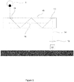
- a fundamental requirement of a head up display is to couple light from an image source to the location required for viewing by the user, known as the exit pupil. This may be accomplished utilising a waveguide system as shown schematically in cross section in Figure 1 .
- Image projection system 11, 12 projects an image into waveguide 10 which couples the image to a user's eye 1 positioned at the exit pupil of the system.
- Waveguide body 10 is optically transmissive such that the user views the real world through the waveguide and the image from the projection system 11, 12 is overlaid onto that view.
- the projector optics 12 are arranged to distribute the projected image over an input region of the waveguide.
- the near-field at that region represents the spatial distribution of light across the projector optic's exit pupil, while the far field represents the image information (each pixel of the image is represented by a discrete ray angle). It is desirable for the image displayed to the user (i.e at the exit pupil) to be focussed a long way from the eye (infinity), since this is the likely focus distance of the real world image onto which the projected image is overlaid.
- Input grating 13 couples the ray 14 into waveguide body 10.
- Input grating 13 may be a diffractive grating which diffracts ray 14 to an angle at which it is trapped within the waveguide 10 by total internal reflection.
- Output grating 15 diffracts light back to its original angles such that it exits the waveguide and propagates to an exit pupil positioned to coincide with the location of eye 1.
- the output grating 15 may also be a diffractive grating.
- Waveguide 10 and the input and output gratings 13, 15 are configured to preserve ray direction between the input and exit pupils to preserve image information. That is, the far field of the light at the exit pupil matches the far field at the input pupil.
- ray 14 For clarity in the figures a single ray 14 is shown, but as will be appreciated this is representative of rays at a range of angles.
- the input light is also spatially distributed and hence ray 14 also represents rays distributed over the input pupil.
- the exit pupil should be large enough to accommodate likely positions of the user's eye in use.
- the waveguide system may be designed to expand the input pupil such that the exit pupil is larger than the input pupil. This expansion is commonly known as pupil replication. The expansion should be performed while preserving the far field and maintaining a constant luminance across the near field.
- This expansion may be achieved utilising both diffractive structures 15 and 16 in the waveguide 10.
- the expansion may be provided in either one dimension or two perpendicular dimensions, using techniques known in the art.
- Gaps or irregular luminance between replicated pupils leads to nonuniformities in the output display, causing changes in perceived brightness in the far field and if the user's eye moves relative to the display.
- Providing expansion in two-dimensions without utilising an impractically sized waveguide can be challenging.
- the expansion ratio increases the luminance for each pupil decreases, thus reducing the perceived brightness for a given source brightness.
- an optical waveguide for a head up display configured to provide pupil expansion in two dimensions and having an input end and an output end, the optical waveguide comprising first and second input regions positioned at the input end; first and second optical gratings configured to direct light received through the first and second input regions respectively such that the light propagates towards the output end of the optical waveguide and is trapped in the optical waveguide by total internal reflection, wherein the propagation direction has a lateral component relative to the direction from the input end to the output end; first and second beam splitters configured to expand the pupil of light propagating in the optical waveguide and received through the first and second input regions respectively, the expansion being in the direction of propagation through the first and second beam splitters; third and fourth optical gratings configured to direct light received from the first and second beam splitters respectively such that the light propagates in a direction substantially aligned with the direction from the input end to the output end; third and fourth beam splitters configured to expand the pupil of light propagating in the optical waveguide and received from the third and fourth optical
- the first and second input regions are positioned to the left and right respectively of an axis from the input end to the output end of the optical waveguide.
- Light received through the first input region may be coupled out of the waveguide by the output grating in a region predominantly to the right of the axis, and light received through the second input region is coupled out of the waveguide by the output grating in a region predominantly to the left of the axis.
- the axis may be positioned at the centre of the output region in a lateral direction.
- optical waveguide according to any preceding claim further comprising first and second projectors to project light into the first and second input regions.
- the light received in each of the first and second input regions may comprise light to form an image and the light represents the full field of view of the image.
- the light received in each of the first and second input regions may comprise light to form part of the full field of view of the image and these two parts are combined by the waveguide to provide the full field of view.
- the light received through the first and second input regions may cross within the optical waveguide in the region of the third and fourth optical gratings.
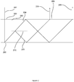
- Figure 2 shows a schematic diagram of aspects of an optical waveguide 200 with a beam splitter 201.
- Light is injected at input region 202 and diffracted by an input diffraction grating 203 such that it is trapped by total internal reflection in the optical waveguide 200.
- the light ray strikes beam splitter 201, which partially transmits ray 204 and partially reflects light ray 205. Each of those rays continues to propagate in the waveguide until they are ejected from the waveguide by output grating 206.
- Beam splitter 201 thus replicates input ray 207 into two output rays 208, 209.
- Input ray 207 may represent an image projected into the input pupil of a waveguide, and thus the beam splitter arrangement achieves pupil replication or expansion in one dimension.
- Figure 3 shows a plan view of an optical waveguide 300 for providing pupil expansion utilising both beam splitters and diffraction gratings in two dimensions. This is a compact design which may provide increased uniformity in the output image compared to other approaches using diffraction gratings alone.
- the waveguide 300 generally comprises an input end 301 and an output end 302. In use light is projected into defined regions at the input end, propagates within the waveguide 300, and is ejected from the waveguide at output end 302. Generally, injected light is for forming an image to be viewed by an eye positioned at the eye box corresponding to the output from the waveguide.
- the direction from the input end to the output end will be referred to as the length of the waveguide or longitudinal direction, and the direction perpendicular to the length, but in the plane of Figure 3 , will be described as the width of the device, or the lateral direction.
- the waveguide 300 utilises two input locations 303, 304, each providing light to part of the device's output (but each providing the full field of view). In the example, each input illuminates half of the output, but unequal division may also be utilised if desirable for a particular application.
- Each input 303, 304 comprises an input optical grating 305, 306.
- the input optical gratings may be fabricated on either face of the waveguide, or may be embedded within the optical waveguide 300 as is known in the art.
- light is projected into inputs 303, 304 to interact with input optical gratings 305, 306.
- the input light is redirected by the input optical gratings 305, 306 such that it propagates within the waveguide 300 at an angle which is trapped within the waveguide 300 by total internal reflection.
- Light is projected into the inputs 303, 304 at an angle such that after interaction with the input gratings 305, 306 light propagates from the input end to the output, but that also comprises a lateral component such that the light also propagates across the width of the waveguide.
- the input light may be injected to propagate at an angle of 60 degrees to the length of the waveguide.
- Beam splitters 307, 308 are located in waveguide 300 such that light propagating from inputs 303, 304 interacts with the respective beam splitter 307, 308 which replicate the pupils in the direction of propagation, as explained in relation to Figure 2 above.
- Figure 4 shows the same waveguide with the addition of indicative pupil shapes to show the effect of each part of the device on the input pupil.
- the pupil is circular 400, 401 and the pupil is expanded to 402, 403 by the beam splitters 307, 308.
- Gratings 309, 310 are provided such that the light propagating from the inputs 303, 304 interacts with a respective grating which is on the opposite lateral side of the waveguide.
- Gratings 309, 310 are configured to diffract the light towards the vertical direction (downwards in Figures 3 and 4 ) such that the propagation is more towards the output end of the device.
- Gratings 309, 310 are also weakly diffractive so that at each interaction with the light trapped within the waveguide some is diffracted towards the output end of the waveguide whilst the remainder continues in its original direction towards the wides of the waveguide. This acts to further expand the pupil from 402, 403 to 404, 405, together covering the full width of the waveguide.
- the light After diffraction from the gratings 309, 310 the light propagates through beam splitters 311, 312 which replicates the pupils in the vertical direction from 405, 405 to 406,407.
- an output grating 313 diffracts light to an angle at which it is no longer trapped by total internal reflection and at which it propagates out of the device to the user's eye.
- the output grating is also weakly diffractive, providing pupil replication to further expand the pupil in the vertical direction from 406, 407 to 408.
- the use of two inputs and two gratings to redirect light between beam splitters provides a compact optical system with pupil replication in two dimensions.
- the use of two gratings reduces the size of each single grating which may improve design flexibility and grating performance.
- Two sets of collimation optics are required to inject light into each of the inputs, but this may offer a number of advantages over previous designs.
- a separate light source can be utilised for each input, thus increasing the available luminance.
- each input supports all of the field of view of the display, but it is also possible to project two partially overlapping images providing an increased brightness for each image.
Landscapes
- Physics & Mathematics (AREA)
- General Physics & Mathematics (AREA)
- Optics & Photonics (AREA)
Priority Applications (8)
| Application Number | Priority Date | Filing Date | Title |
|---|---|---|---|
| EP18275036.4A EP3537201A1 (fr) | 2018-03-07 | 2018-03-07 | Structure de guide d'ondes pour affichages tête haute |
| KR1020207026001A KR102775782B1 (ko) | 2018-03-07 | 2019-03-05 | 헤드업 디스플레이를 위한 도파관 구조 |
| US16/977,701 US12038582B2 (en) | 2018-03-07 | 2019-03-05 | Waveguide structure for head up displays |
| PCT/GB2019/050602 WO2019171038A1 (fr) | 2018-03-07 | 2019-03-05 | Structure de guide d'ondes pour des affichages tête haute |
| BR112020018059-9A BR112020018059B1 (pt) | 2018-03-07 | 2019-03-05 | Guia de ondas óptico para um monitor de alertas |
| EP19709551.6A EP3762763A1 (fr) | 2018-03-07 | 2019-03-05 | Structure de guide d'ondes pour des affichages tête haute |
| KR1020257006490A KR20250030537A (ko) | 2018-03-07 | 2019-03-05 | 헤드업 디스플레이를 위한 도파관 구조 |
| US18/753,889 US20240345403A1 (en) | 2018-03-07 | 2024-06-25 | Waveguide structure for head up displays |
Applications Claiming Priority (1)
| Application Number | Priority Date | Filing Date | Title |
|---|---|---|---|
| EP18275036.4A EP3537201A1 (fr) | 2018-03-07 | 2018-03-07 | Structure de guide d'ondes pour affichages tête haute |
Publications (1)
| Publication Number | Publication Date |
|---|---|
| EP3537201A1 true EP3537201A1 (fr) | 2019-09-11 |
Family
ID=61599074
Family Applications (1)
| Application Number | Title | Priority Date | Filing Date |
|---|---|---|---|
| EP18275036.4A Ceased EP3537201A1 (fr) | 2018-03-07 | 2018-03-07 | Structure de guide d'ondes pour affichages tête haute |
Country Status (1)
| Country | Link |
|---|---|
| EP (1) | EP3537201A1 (fr) |
Cited By (2)
| Publication number | Priority date | Publication date | Assignee | Title |
|---|---|---|---|---|
| WO2021134674A1 (fr) * | 2019-12-31 | 2021-07-08 | 诚瑞光学(常州)股份有限公司 | Dispositif d'écran d'affichage près de l'œil |
| US12038582B2 (en) | 2018-03-07 | 2024-07-16 | Snap Inc. | Waveguide structure for head up displays |
Citations (4)
| Publication number | Priority date | Publication date | Assignee | Title |
|---|---|---|---|---|
| US20100246003A1 (en) * | 2007-12-18 | 2010-09-30 | Bae Systems Plc | projection displays |
| US7907342B2 (en) * | 2005-09-07 | 2011-03-15 | Bae Systems Plc | Projection display |
| WO2016046514A1 (fr) * | 2014-09-26 | 2016-03-31 | LOKOVIC, Kimberly, Sun | Dispositif de poursuite optique à guide d'ondes holographique |
| WO2017060665A1 (fr) * | 2015-10-05 | 2017-04-13 | Milan Momcilo Popovich | Afficheur à guide d'ondes |
-
2018
- 2018-03-07 EP EP18275036.4A patent/EP3537201A1/fr not_active Ceased
Patent Citations (4)
| Publication number | Priority date | Publication date | Assignee | Title |
|---|---|---|---|---|
| US7907342B2 (en) * | 2005-09-07 | 2011-03-15 | Bae Systems Plc | Projection display |
| US20100246003A1 (en) * | 2007-12-18 | 2010-09-30 | Bae Systems Plc | projection displays |
| WO2016046514A1 (fr) * | 2014-09-26 | 2016-03-31 | LOKOVIC, Kimberly, Sun | Dispositif de poursuite optique à guide d'ondes holographique |
| WO2017060665A1 (fr) * | 2015-10-05 | 2017-04-13 | Milan Momcilo Popovich | Afficheur à guide d'ondes |
Cited By (2)
| Publication number | Priority date | Publication date | Assignee | Title |
|---|---|---|---|---|
| US12038582B2 (en) | 2018-03-07 | 2024-07-16 | Snap Inc. | Waveguide structure for head up displays |
| WO2021134674A1 (fr) * | 2019-12-31 | 2021-07-08 | 诚瑞光学(常州)股份有限公司 | Dispositif d'écran d'affichage près de l'œil |
Similar Documents
| Publication | Publication Date | Title |
|---|---|---|
| US20240345403A1 (en) | Waveguide structure for head up displays | |
| US20220413283A1 (en) | Waveguide structure | |
| US11262581B2 (en) | Axially asymmetric image source for head-up displays | |
| US11256100B2 (en) | Head-mounted display with pivoting imaging light guide | |
| US10795165B2 (en) | Multiple waveguide structure for colour displays | |
| US10795156B2 (en) | Waveguide structure | |
| GB2573611A (en) | Waveguide structure for head up displays | |
| TW202319789A (zh) | 具有在輸出區上游的分束器之波導 | |
| EP3361147A1 (fr) | Structure de guide d'onde | |
| EP3537201A1 (fr) | Structure de guide d'ondes pour affichages tête haute | |
| KR20200102441A (ko) | 헤드-업 디스플레이 | |
| US20240385364A1 (en) | Double-sided waveguide | |
| US20230161163A1 (en) | Optical device | |
| CN112612138B (zh) | 一种波导显示系统 | |
| US20230045957A1 (en) | Multi-source light-guiding illuminator | |
| BR112020018059B1 (pt) | Guia de ondas óptico para um monitor de alertas | |
| JP2025535963A (ja) | コンパクトな回折光学素子を有する画像光ガイド | |
| EP3474061A1 (fr) | Source d'image asymétrique pour affichages tête haute | |
| HK40111797A (zh) | 具有枢转成像光导的头戴式显示器 | |
| FI20215677A1 (en) | Optical waveguide arrangement with improved capacity | |
| GB2567662A (en) | Asymmetric image source for head up displays |
Legal Events
| Date | Code | Title | Description |
|---|---|---|---|
| PUAI | Public reference made under article 153(3) epc to a published international application that has entered the european phase |
Free format text: ORIGINAL CODE: 0009012 |
|
| AK | Designated contracting states |
Kind code of ref document: A1 Designated state(s): AL AT BE BG CH CY CZ DE DK EE ES FI FR GB GR HR HU IE IS IT LI LT LU LV MC MK MT NL NO PL PT RO RS SE SI SK SM TR |
|
| AX | Request for extension of the european patent |
Extension state: BA ME |
|
| STAA | Information on the status of an ep patent application or granted ep patent |
Free format text: STATUS: THE APPLICATION HAS BEEN REFUSED |
|
| 18R | Application refused |
Effective date: 20191012 |