EP3537488A1 - Ermittlung und anlegen einer spannung an einen piezoelektrischen aktuator - Google Patents
Ermittlung und anlegen einer spannung an einen piezoelektrischen aktuator Download PDFInfo
- Publication number
- EP3537488A1 EP3537488A1 EP18160414.1A EP18160414A EP3537488A1 EP 3537488 A1 EP3537488 A1 EP 3537488A1 EP 18160414 A EP18160414 A EP 18160414A EP 3537488 A1 EP3537488 A1 EP 3537488A1
- Authority
- EP
- European Patent Office
- Prior art keywords
- pea
- voltage
- relation
- determining
- hysteresis
- Prior art date
- Legal status (The legal status is an assumption and is not a legal conclusion. Google has not performed a legal analysis and makes no representation as to the accuracy of the status listed.)
- Granted
Links
Images



Classifications
-
- H—ELECTRICITY
- H10—SEMICONDUCTOR DEVICES; ELECTRIC SOLID-STATE DEVICES NOT OTHERWISE PROVIDED FOR
- H10N—ELECTRIC SOLID-STATE DEVICES NOT OTHERWISE PROVIDED FOR
- H10N30/00—Piezoelectric or electrostrictive devices
- H10N30/80—Constructional details
- H10N30/802—Circuitry or processes for operating piezoelectric or electrostrictive devices not otherwise provided for, e.g. drive circuits
-
- H—ELECTRICITY
- H02—GENERATION; CONVERSION OR DISTRIBUTION OF ELECTRIC POWER
- H02N—ELECTRIC MACHINES NOT OTHERWISE PROVIDED FOR
- H02N2/00—Electric machines in general using piezoelectric effect, electrostriction or magnetostriction
- H02N2/02—Electric machines in general using piezoelectric effect, electrostriction or magnetostriction producing linear motion, e.g. actuators; Linear positioners ; Linear motors
- H02N2/06—Drive circuits; Control arrangements or methods
- H02N2/062—Small signal circuits; Means for controlling position or derived quantities, e.g. for removing hysteresis
-
- H—ELECTRICITY
- H04—ELECTRIC COMMUNICATION TECHNIQUE
- H04N—PICTORIAL COMMUNICATION, e.g. TELEVISION
- H04N23/00—Cameras or camera modules comprising electronic image sensors; Control thereof
- H04N23/50—Constructional details
- H04N23/52—Elements optimising image sensor operation, e.g. for electromagnetic interference [EMI] protection or temperature control by heat transfer or cooling elements
-
- H—ELECTRICITY
- H04—ELECTRIC COMMUNICATION TECHNIQUE
- H04N—PICTORIAL COMMUNICATION, e.g. TELEVISION
- H04N23/00—Cameras or camera modules comprising electronic image sensors; Control thereof
- H04N23/50—Constructional details
- H04N23/54—Mounting of pick-up tubes, electronic image sensors, deviation or focusing coils
-
- H—ELECTRICITY
- H04—ELECTRIC COMMUNICATION TECHNIQUE
- H04N—PICTORIAL COMMUNICATION, e.g. TELEVISION
- H04N23/00—Cameras or camera modules comprising electronic image sensors; Control thereof
- H04N23/57—Mechanical or electrical details of cameras or camera modules specially adapted for being embedded in other devices
-
- H—ELECTRICITY
- H04—ELECTRIC COMMUNICATION TECHNIQUE
- H04N—PICTORIAL COMMUNICATION, e.g. TELEVISION
- H04N23/00—Cameras or camera modules comprising electronic image sensors; Control thereof
- H04N23/60—Control of cameras or camera modules
- H04N23/67—Focus control based on electronic image sensor signals
-
- G—PHYSICS
- G02—OPTICS
- G02B—OPTICAL ELEMENTS, SYSTEMS OR APPARATUS
- G02B7/00—Mountings, adjusting means, or light-tight connections, for optical elements
- G02B7/02—Mountings, adjusting means, or light-tight connections, for optical elements for lenses
- G02B7/04—Mountings, adjusting means, or light-tight connections, for optical elements for lenses with mechanism for focusing or varying magnification
- G02B7/08—Mountings, adjusting means, or light-tight connections, for optical elements for lenses with mechanism for focusing or varying magnification adapted to co-operate with a remote control mechanism
-
- G—PHYSICS
- G03—PHOTOGRAPHY; CINEMATOGRAPHY; ANALOGOUS TECHNIQUES USING WAVES OTHER THAN OPTICAL WAVES; ELECTROGRAPHY; HOLOGRAPHY
- G03B—APPARATUS OR ARRANGEMENTS FOR TAKING PHOTOGRAPHS OR FOR PROJECTING OR VIEWING THEM; APPARATUS OR ARRANGEMENTS EMPLOYING ANALOGOUS TECHNIQUES USING WAVES OTHER THAN OPTICAL WAVES; ACCESSORIES THEREFOR
- G03B2205/00—Adjustment of optical system relative to image or object surface other than for focusing
- G03B2205/0053—Driving means for the movement of one or more optical element
- G03B2205/0061—Driving means for the movement of one or more optical element using piezoelectric actuators
Definitions
- the invention relates to piezoelectric actuators (PEAs) and systems involving such PEAs, in particular the invention relates to compensating for non-linear phenomena in such systems.
- PEAs piezoelectric actuators
- WO 2017/118732 describes an electronic circuit for controlling charging of a piezoelectric load arranged as an actuator in a deformable lens.
- Piezo creep is the expression of the slow realignment of the crystal domains in a constant input voltage over time. If the operating voltage of a PZT is changed, after the voltage change is complete, the remnant polarization continues to change, manifesting itself in a slow creep. In closed loop setups - where the output is repeatedly checked against a desired value in a feedback loop to correct the voltage applied to the PEA - they can relatively easy be compensated for. The price, however, is time and power consumption which are disadvantageous for many applications.
- the present invention is an alternative to the prior art.
- the invention provides a method for determining and applying a voltage to a piezoelectric actuator (PEA) to achieve a given setpoint displacement, the method comprising:
- the PEA displacement measure is any direct or indirect measure of the PEA displacement, such as a parameter proportional thereto or to which there is a known relation.
- the displacement measure may be optical power, a sharpness score, focal length, etc.
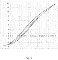
- the method presumes a previously determined relation d(V) between voltage and displacement, which is a common characterization for PEAs, see also Figure 1 .
- d(V) typically show hysteresis and is usually required when compensating for hysteresis.
- Such relations can be determined and expressed in different ways - e.g. tables, curves, interpolated curves, algebraic functions, etc. - and is considered part of the state of the art. Examples of analysis and further description of hysteresis and creep in PEAs may be found in Minase et al.
- the method according to the first aspect provides the advantage that the calculated relation d(tt) between the displacement measure and transition time at the same time characterises the individual PEA, has no hysteresis, and does not vary with time or usage of the PEA. This is in contrast to the relations used to calculate d(tt), which both have significant hysteresis and are both prone to change with time and usage history. By determining a current version of one of these relations at a later stage, the other can be derived using d(tt), thus compensating for the changes. It is important to note that the transition time is one of more related properties of the PEA that can be used for this purpose.
- the capacitance of a PEA is a function of the geometry and the dielectric permittivity of the material, and is thus more or less a material parameter, but not necessarily trivial to measure without a sophisticated measurement set-up.
- the transition time (the time to charge or discharge the PEA) is strongly correlated with capacitance, and can be used as a method to measure the capacitance.
- the determination of relation d cal (V) during the initial calibration procedure preferably comprises determining at least two calibration pairs by measuring voltages corresponding to at least two calibration displacement measures, and fitting a typical d(V) curve to the determined calibration pairs.
- the step of determining the voltage to be applied to the PEA preferably comprises using d c (V) in a hysteresis compensation algorithm to determine a hysteresis compensated voltage, V hc , to be applied to the PEA to achieve d sp .
- the hysteresis compensation algorithm is preferably a method according to the fifth aspect to be described later herein.
- the variables and parameters used in this and other aspects are temperature dependent, and need to be calibrated for the current temperature when used.
- the temperature dependencies are typically well-known.
- the current temperature may be determined in different ways known from the prior art.
- the temperature dependence of the ASIC oscillator is significant, and can be used to estimate temperature. Since the oscillator frequency is used to measure tt, tt will also have a temperature dependence. But, since the temperature dependence of the oscillator is well characterized by the manufacturer, the temperature dependence of the transition time is easily calibrated out.
- the step of determining the voltage to be applied to the PEA using the compensated relation, d c (V), comprises obtaining a current temperature and selecting a corresponding temperature compensation parameter for additional lenses in the camera module from a list.
- the method further comprises recording a temperature of the PEA during the initial calibration and at the time of determining tt new (V), and compensating for the temperature dependencies of the determined relations before calculating the compensated relation d c (V).
- the PEA is a piezo electric film arranged on a flexible membrane to deform a shape of the membrane upon actuation of the PEA.
- the determination of the voltage to be applied to the PEA is an open-loop process, such as without a feedback loop where a displacement measure resulting from a voltage applied to the PEA is compared to the setpoint displacement measure.
- the invention provides an actuator system comprising a PEA, a piezo driver connected to drive the PEA, and a processing unit connected to the piezo driver and holding software for controlling the piezo driver, wherein the software is adapted to implement the method according to the first aspect.
- the invention provides an actuator system comprising a PEA, a piezo driver connected to drive the PEA, and a processing unit connected to the piezo driver and holding software for controlling the piezo driver, wherein:
- the piezo driver is an electronic circuit providing or drawing current to set the electric field over the piezo crystal, thus controlling the strain in the PEA.
- the piezo driver is preferably implemented in an ASIC.
- the software is further adapted to:
- the software carries out an open loop algorithm in that it determines the voltage to be applied to the PEA without a feedback loop where a displacement measure resulting from a voltage applied to the PEA is compared to the setpoint displacement measure.
- the PEA actuator system is used to control an adjustable focus lens assembly in a camera module and the displacement measure is a sharpness score or focus distance of the camera module.
- the PEA actuator system is combined with an adjustable focus lens assembly in a camera module and the PEA is a piezo electric film arranged on a flexible membrane of the adjustable focus lens assembly to deform a shape of the membrane upon actuation of the PEA.
- the adjustable focus lens assembly comprises a bendable transparent lens cover, a transparent back window and a transparent, deformable lens body sandwiched between the lens cover and the back window to form a lens, and wherein the PEA a piezo film on the lens cover for changing an overall shape of the lens.
- the invention provides an adjustable focus lens assembly comprising a deformable, non-fluid lens body sandwiched between an optical support and a transparent, flexible membrane to form a lens, with a PEA in the form of a film arranged on the flexible membrane to deform the flexible membrane to change the focus of the lens, the lens assembly further comprising the actuator system according to the third aspect.
- the invention provides a method for compensating for hysteresis when applying a voltage to a piezoelectric actuator (PEA) in a tunable lens incorporating such PEA to control its optical power, the method comprising:
- providing a relation d(V) between a PEA displacement measure and voltage comprises using a compensated relation d c (V) using the method according to the first aspect.
- the adjustable focus lens assembly can for example be a deformable, non-fluid lens body sandwiched between an optical support and a transparent, flexible membrane to form a lens, with a PEA in the form of a film arranged on the flexible membrane to deform the flexible membrane to change the focus of the lens.
- the PEA of the lens assembly can then be connected to a piezo driver involving a processing unit connected to the piezo driver and holding software for controlling the piezo driver.
- Such adjustable lens assembly is described in e.g. WO 2008/035983 .
- the various measurements described and shown are obtained from a setup on a laboratory bench, and in this setup the displacement measure is optical power measured in dioptre. Measurement of optical power, however, is not practical in normal use of the invention, where other displacement measures, preferably a sharpness measure from an auto focus sensor, may be used.
- optical power (OP) and displacement measure (d) is used interchangeably.
- DAC voltage
- Piezo creep is a well known effect in piezoelectric materials, see e.g. J. Minase, T.-F. Lu, B. Cazzolato, and S. Grainger, "Adaptive identification of hysteresis and creep in piezoelectric stack actuators," Int. J. Adv. Manuf. Technol., vol. 46, no. 9-12, pp. 913-921, Feb. 2010 , and Y. Liu, J. Shan, U. Gabbert, and N. Qi, "Hysteresis and creep modeling and compensation for a piezoelectric actuator using a fractional-order Maxwell resistive capacitor approach," Smart Mater. Struct., vol. 22, no. 11, p. 115020, Nov.
- the oscillation frequency of the ASIC and other parts such as molded plastic lenses in the camera module vary significantly with temperature. These variations, however, are either well documented from the manufacturer or can be measured and calibrated for using with the current temperature.
- test chart For the calibration of the camera module a test chart is set up at a macro position (e.g. 10 cm), and at an "infinity" position (e.g. 2 m).
- the DAC value (voltage) to reach maximum sharpness at each distance is recorded and stored to establish two points on the d(V) curve.
- the calibration procedure can involve starting from V min , measuring the maximum sharpness at infinity (V infinity ) on the upward voltage curve (d ⁇ (V), lower hysteresis), then go to V max , and find the maximum sharpness at macro (V macro ) on the downward voltage curve (d ⁇ (V), upper hysteresis curve), or vice versa, in order to have one point on the upper and one on the lower hysteresis curve.
- the voltage steps should be done in small enough steps to give the required accuracy in the calibrated values, and the sequence should be from V min and upwards, until V max , then downwards until both values are located.
- the transition time (tt) can be recorded for several voltage steps going up and going down in voltage to determine a relation tt(V).
- the used charging/discharging current need not be known if it is the same for all measurements. Alternatively, it can vary, but then it need to be known so that tt can be adjusted accordingly.
- the sequence and size of the voltage steps can vary in order to give the optimal reading of transition time vs voltage.
- the current temperature can also be determined, e.g. from the image sensor of via the temperature dependence of the oscillator frequency of the ASIC.
- the PEA capacitance can be measured using a small (100mV to 1V) superimposed AC voltage.
- the complex impedance of the PEA is measured, and the (change in) capacitance is deduced.
- Using a superimposed AC would enable capacitance measurement at constant actuator voltage, which is not possible with the transition time measurement. This method, however, requires a more complex ASIC.
- a typical or template d(V) curve can be provided in storage and fitted to the two calibrated values V macro and V infinity values from the calibration to estimate d(V) over the whole voltage range. This curve is then used along with the tt(V) curve from the second part of the calibration (corrected for the current temperature) to calculate the characteristic d(tt) relation for the given camera module. This characteristic relationship is stored, either as a table of data or as a sequence of parameters that determine the curve with good accuracy (polynomial).
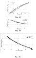
- Figures 3A and 3B illustrate hysteresis and creep effects in relations between optical power and voltage (3A) and capacitance and voltage (3B), showing the relations before (full curves) and after (dashed curves) a 2 days biasing at 85°C (corresponding to approximately 1 year of use in a typical mission profile for a mobile phone camera user).
- That the optical power vs capacitance relationship is a characteristic for at a given temperature, also means that the temperature should ideally be the same during the initial calibration and the later calculation of the compensated relation d c (V). Since this is usually not practically possible, the temperature of the PEA can be recorded during the initial calibration and at the time of determining tt new (V). Then, the determined relations can be compensated for the difference in temperature before calculating the compensated relation d c (V).
- the clock frequency of the PEA driver varies with temperature in a predictable fashion, and assuming that the PEA and PEA driver has the same temperature, a temperature of the driver and thus the PEA can be estimated by measuring this clock frequency.
- the capacitance is, however, not a value that can be easily measured during real life operation in a camera module.
- the optical power displacement measure
- the OP vs. capacitance relation can be replaced by a displacement measure vs. transition time relation, d(tt). This is illustrated in Figures 4A-C showing tt(V) ( Figure 4A ), OP(V) ( Figure 4B ), and OP(tt) ( Figure 4C ) before (full curves) and after (dashed curves) 2 days biasing at 85°C as for Figures 3A-C .
- the characteristic relation d(tt) - calculated from d(V) and tt(V) during camera module calibration - is invariant to the biasing history. Therefore, at any later stage, the current hysteresis curve, d c (V) for a specific actuator system can be determined from the characteristic relation d(tt) by measuring the transition time vs. voltage relation at any time in the life time of the camera module. This determined current hysteresis curve will thus be compensated for creep effects from the biasing history.
- Such tt(V) measurement can be performed by the software controlling the piezo driver, by applying a sequence of voltages to the PEA and measure the transition times between the voltages. This measurement can typically take 5-100 ms, depending on the number of steps and repetitions, and can be carried out during the initialization of the camera module before use.
- the compensated curve, d c (V) may be used as input to the hysteresis compensation described hereunder.
- a method for compensating hysteresis according to an embodiment of the invention is described.
- the method is described in relation to a camera module, and uses as a starting point either the typical d(V) fitted to by use of at least the calibration values V macro and Vinfinite, or the compensated d c (V).
- the actuator system receives either a setpoint optical power (or focus distance or other displacement measure), d sp , or a setpoint voltage, V s , since there, in the absence of hysteresis, is a one to one mapping between voltage and displacement. If a setpoint voltage is received, a target optical power is determined from the upward optical power v voltage curve, d ⁇ (V). The object of the method is to search for and find a hysteresis compensated voltage, V hc , that will produce the setpoint or target optical power when applied to the PEA.
- Voltage turning points are the voltage positions where the difference between input voltage have changed, from increments to decrements or vice versa.
- the actuator system also receives the history information, that is the last upper and lower voltage turning points, V upper and V lower , that the new input voltage lies between.
- V upper and V lower the last upper and lower voltage turning points
- d sp lies between the optical power values at the last upper and lower voltage turning points, d upper and d lower . If it does not lie between these values, then previous upper and lower turning points are taken from the history information, until turning points are found that d sp lies between.
- the current upper or lower turning point is then updated and the previous turning point added to the turning point buffer.
- the defined voltage range [V lower ;V upper ] is then used for a binary search.
- the binary search starts at V s and the corresponding optical power is calculated by getting the optical power corresponding to a calculated hysteresis ratio, r(V), as will be defined in more detail in the following sections.
- a new input voltage is calculated. If the calculated optical power is less than the target optical power, then the lower end of the search range is set to the last input voltage, otherwise the upper end of the search range is set to the last input voltage. The new input voltage for the next iteration is then calculated from the mean of the upper and lower ends of the search range. The search iterates until the calculated optical power is within the threshold of the target optical power at which point this voltage value is output as the updated hysteresis corrected voltage. This process is a normal binary search and is illustrated in Figure 5 .
- the hysteresis ratio calculation consists of the following calculations
- This optical power is then checked in the binary search if it is within the threshold of the target optical power, otherwise a new search iteration is started. This is illustrated in Figure 8 .
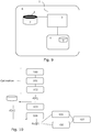
- Figure 9 illustrates an actuator system 1 according to an embodiment of the invention comprising a PEA 2, a piezo driver 3 connected to drive the PEA, and a processing unit 4 connected to the piezo driver and holding software for controlling the piezo driver.
- the software can be stored in memory 5 being part of the processing unit.
- the actuator system 1 is combined with an adjustable focus lens assembly 7 to form part of a camera module 6.
- the PEA can be a piezo electric film arranged on a flexible membrane to deform a shape of the membrane upon actuation of the PEA.
- Figure 10 is a flow chart illustrating the method and the software algorithms for compensating for piezo creep when applying a voltage to a PEA according to embodiments of the invention.
- the flow chart illustrates the steps of:
Landscapes
- Engineering & Computer Science (AREA)
- Multimedia (AREA)
- Signal Processing (AREA)
- Physics & Mathematics (AREA)
- Electromagnetism (AREA)
- Lens Barrels (AREA)
Priority Applications (5)
| Application Number | Priority Date | Filing Date | Title |
|---|---|---|---|
| DK18160414.1T DK3537488T3 (da) | 2018-03-07 | 2018-03-07 | Bestemmelse og påføring af en spænding på en piezoelektrisk aktuator |
| EP18160414.1A EP3537488B1 (de) | 2018-03-07 | 2018-03-07 | Ermittlung und anlegen einer spannung an einen piezoelektrischen aktuator |
| CN201980030945.9A CN112385055B (zh) | 2018-03-07 | 2019-03-07 | 压电致动器的电压的确定与施加 |
| US16/978,561 US11870371B2 (en) | 2018-03-07 | 2019-03-07 | Determining and applying a voltage to a piezoelectric actuator |
| PCT/EP2019/055653 WO2019170793A1 (en) | 2018-03-07 | 2019-03-07 | Determining and applying a voltage to a piezoelectric actuator |
Applications Claiming Priority (1)
| Application Number | Priority Date | Filing Date | Title |
|---|---|---|---|
| EP18160414.1A EP3537488B1 (de) | 2018-03-07 | 2018-03-07 | Ermittlung und anlegen einer spannung an einen piezoelektrischen aktuator |
Publications (2)
| Publication Number | Publication Date |
|---|---|
| EP3537488A1 true EP3537488A1 (de) | 2019-09-11 |
| EP3537488B1 EP3537488B1 (de) | 2020-10-21 |
Family
ID=61616783
Family Applications (1)
| Application Number | Title | Priority Date | Filing Date |
|---|---|---|---|
| EP18160414.1A Active EP3537488B1 (de) | 2018-03-07 | 2018-03-07 | Ermittlung und anlegen einer spannung an einen piezoelektrischen aktuator |
Country Status (5)
| Country | Link |
|---|---|
| US (1) | US11870371B2 (de) |
| EP (1) | EP3537488B1 (de) |
| CN (1) | CN112385055B (de) |
| DK (1) | DK3537488T3 (de) |
| WO (1) | WO2019170793A1 (de) |
Cited By (1)
| Publication number | Priority date | Publication date | Assignee | Title |
|---|---|---|---|---|
| EP3792988A1 (de) * | 2019-09-10 | 2021-03-17 | poLight ASA | Vorwärtskopplungsbestimmung eines steuersignals für einen piezoaktor |
Families Citing this family (5)
| Publication number | Priority date | Publication date | Assignee | Title |
|---|---|---|---|---|
| EP4314930B1 (de) | 2021-03-30 | 2025-03-19 | poLight ASA | Sensorbasierte steuerung einer optischen vorrichtung mit variabler optischer brechkraft oder variabler strahlablenkung |
| WO2023124181A1 (zh) * | 2021-12-31 | 2023-07-06 | 荣耀终端有限公司 | 摄像模组及电子装置 |
| CN114339052B (zh) * | 2021-12-31 | 2024-05-07 | 上海艾为电子技术股份有限公司 | 测量值的补偿方法、系统和电路、驱动芯片、拍摄模组 |
| CN115167148B (zh) * | 2022-08-12 | 2025-05-16 | 中国科学院长春光学精密机械与物理研究所 | 一种压电执行器的双时间尺度状态观测方法及系统 |
| US20250076634A1 (en) * | 2023-08-28 | 2025-03-06 | Meta Platforms Technologies, Llc | Piezoelectric actuator with capacitance sensing for optical power control |
Citations (4)
| Publication number | Priority date | Publication date | Assignee | Title |
|---|---|---|---|---|
| US4862207A (en) * | 1987-05-21 | 1989-08-29 | Olympus Optical Company Limited | Diaphragm apparatus for camera |
| WO2008035983A1 (en) | 2006-09-21 | 2008-03-27 | Sinvent As | Polymer lens |
| US20120212099A1 (en) * | 2011-02-21 | 2012-08-23 | Renesas Electronics Corporation | Device for driving a piezoelectric element |
| EP3190637A1 (de) * | 2016-01-06 | 2017-07-12 | PoLight AS | Elektronische schaltung zur ladesteuerung einer piezoelektrischen last |
Family Cites Families (7)
| Publication number | Priority date | Publication date | Assignee | Title |
|---|---|---|---|---|
| US20030168939A1 (en) * | 2001-12-10 | 2003-09-11 | Samad Talebpour | Device and method of driving piezoelectric actuators for fast switching of wavelengths in a fiber-bragg grating |
| US7312554B2 (en) * | 2004-04-02 | 2007-12-25 | Adaptivenergy, Llc | Piezoelectric devices and methods and circuits for driving same |
| CN100508233C (zh) * | 2004-06-24 | 2009-07-01 | 物理设备(Pi)两合公司 | 操作压电执行单元的方法 |
| CN100570283C (zh) * | 2005-06-29 | 2009-12-16 | 精工爱普生株式会社 | 压电致动器的驱动量检测装置及电子设备 |
| US8115367B2 (en) * | 2007-11-26 | 2012-02-14 | Sii Nanotechnology Inc. | Piezoelectric actuator provided with a displacement meter, piezoelectric element, and positioning device |
| JP5842417B2 (ja) * | 2011-07-05 | 2016-01-13 | セイコーエプソン株式会社 | 圧電素子駆動回路、および流体噴射装置 |
| SG11201609924RA (en) * | 2014-05-29 | 2016-12-29 | Brilliant Light Power Inc | Electrical power generation systems and methods regarding same |
-
2018
- 2018-03-07 DK DK18160414.1T patent/DK3537488T3/da active
- 2018-03-07 EP EP18160414.1A patent/EP3537488B1/de active Active
-
2019
- 2019-03-07 WO PCT/EP2019/055653 patent/WO2019170793A1/en not_active Ceased
- 2019-03-07 CN CN201980030945.9A patent/CN112385055B/zh active Active
- 2019-03-07 US US16/978,561 patent/US11870371B2/en active Active
Patent Citations (5)
| Publication number | Priority date | Publication date | Assignee | Title |
|---|---|---|---|---|
| US4862207A (en) * | 1987-05-21 | 1989-08-29 | Olympus Optical Company Limited | Diaphragm apparatus for camera |
| WO2008035983A1 (en) | 2006-09-21 | 2008-03-27 | Sinvent As | Polymer lens |
| US20120212099A1 (en) * | 2011-02-21 | 2012-08-23 | Renesas Electronics Corporation | Device for driving a piezoelectric element |
| EP3190637A1 (de) * | 2016-01-06 | 2017-07-12 | PoLight AS | Elektronische schaltung zur ladesteuerung einer piezoelektrischen last |
| WO2017118732A1 (en) | 2016-01-06 | 2017-07-13 | Polight As | Electronic circuit for controlling charging of a piezoelectric load |
Non-Patent Citations (5)
| Title |
|---|
| CHANGHAI ET AL.: "Hysteresis and creep compensation for piezoelectric actuator in open-loop operation", SENSORS AND ACTUATORS A, vol. 122, 2005, pages 124 - 130, XP025325270, DOI: doi:10.1016/j.sna.2005.03.056 |
| J. MINASE; T.-F. LU; B. CAZZOLATO; S. GRAINGER: "Adaptive identification of hysteresis and creep in piezoelectric stack actuators", INT. J. ADV. MANUF. TECHNOL., vol. 46, no. 9-12, February 2010 (2010-02-01), pages 913 - 921, XP019776872 |
| KUHNEN; KREJCI: "Compensation of complex hysteresis and creep effects in Piezoelectric actuated systems", IEEE TRANSACTIONS ON AUTOMATIC CONTROL, vol. 54, 2009, XP011252867 |
| MINASE ET AL.: "Adaptive identification of hysteresis and creep in piezoelectric stack actuators", INT J ADV MANUF TECHNOL, vol. 46, 2010, pages 913 - 921, XP019776872 |
| Y. LIU; J. SHAN; U. GABBERT; N. QI: "Hysteresis and creep modeling and compensation for a piezoelectric actuator using a fractional-order Maxwell resistive capacitor approach", SMART MATER. STRUCT., vol. 22, no. 11, November 2013 (2013-11-01), pages 115020, XP020252690, DOI: doi:10.1088/0964-1726/22/11/115020 |
Cited By (5)
| Publication number | Priority date | Publication date | Assignee | Title |
|---|---|---|---|---|
| EP3792988A1 (de) * | 2019-09-10 | 2021-03-17 | poLight ASA | Vorwärtskopplungsbestimmung eines steuersignals für einen piezoaktor |
| WO2021048103A1 (en) * | 2019-09-10 | 2021-03-18 | Polight Asa | Feedforward determination of a driving signal for a piezo actuator |
| KR20220061171A (ko) * | 2019-09-10 | 2022-05-12 | 포라이트 에이에스에이 | 압전 액추에이터 구동 신호의 피드포워드 결정 |
| US12210267B2 (en) | 2019-09-10 | 2025-01-28 | Polight Asa | Feedforward determination of a driving signal for a piezo actuator |
| AU2020344807B2 (en) * | 2019-09-10 | 2026-01-22 | Polight Asa | Feedforward determination of a driving signal for a piezo actuator |
Also Published As
| Publication number | Publication date |
|---|---|
| CN112385055A (zh) | 2021-02-19 |
| US11870371B2 (en) | 2024-01-09 |
| CN112385055B (zh) | 2024-05-03 |
| EP3537488B1 (de) | 2020-10-21 |
| WO2019170793A1 (en) | 2019-09-12 |
| US20210021212A1 (en) | 2021-01-21 |
| US20210336560A9 (en) | 2021-10-28 |
| DK3537488T3 (da) | 2021-01-18 |
Similar Documents
| Publication | Publication Date | Title |
|---|---|---|
| EP3537488B1 (de) | Ermittlung und anlegen einer spannung an einen piezoelektrischen aktuator | |
| US11474284B2 (en) | Liquid lens control systems and methods | |
| CN101304691B (zh) | 超声波探头及超声波诊断装置 | |
| US11567242B2 (en) | Liquid lens systems | |
| US20110277462A1 (en) | Control of a shape memory alloy actuation arrangement | |
| EP4029067B1 (de) | Vorwärtskopplungsbestimmung eines steuersignals für einen piezoelektrischen aktor | |
| CN111065933A (zh) | 用于储能系统的充电容量计算设备和方法 | |
| JP6691059B2 (ja) | マイクロフォンアセンブリおよびマイクロフォンアセンブリの温度依存性を低減する方法 | |
| US6798718B1 (en) | Sensor timepiece, sensor timepiece data input system and method, and computer readable recording medium | |
| JP2014171199A (ja) | 温度補償発振器及び温度補償発振器の製造方法 |
Legal Events
| Date | Code | Title | Description |
|---|---|---|---|
| PUAI | Public reference made under article 153(3) epc to a published international application that has entered the european phase |
Free format text: ORIGINAL CODE: 0009012 |
|
| STAA | Information on the status of an ep patent application or granted ep patent |
Free format text: STATUS: THE APPLICATION HAS BEEN PUBLISHED |
|
| AK | Designated contracting states |
Kind code of ref document: A1 Designated state(s): AL AT BE BG CH CY CZ DE DK EE ES FI FR GB GR HR HU IE IS IT LI LT LU LV MC MK MT NL NO PL PT RO RS SE SI SK SM TR |
|
| AX | Request for extension of the european patent |
Extension state: BA ME |
|
| STAA | Information on the status of an ep patent application or granted ep patent |
Free format text: STATUS: REQUEST FOR EXAMINATION WAS MADE |
|
| 17P | Request for examination filed |
Effective date: 20200310 |
|
| RBV | Designated contracting states (corrected) |
Designated state(s): AL AT BE BG CH CY CZ DE DK EE ES FI FR GB GR HR HU IE IS IT LI LT LU LV MC MK MT NL NO PL PT RO RS SE SI SK SM TR |
|
| GRAP | Despatch of communication of intention to grant a patent |
Free format text: ORIGINAL CODE: EPIDOSNIGR1 |
|
| STAA | Information on the status of an ep patent application or granted ep patent |
Free format text: STATUS: GRANT OF PATENT IS INTENDED |
|
| INTG | Intention to grant announced |
Effective date: 20200428 |
|
| GRAJ | Information related to disapproval of communication of intention to grant by the applicant or resumption of examination proceedings by the epo deleted |
Free format text: ORIGINAL CODE: EPIDOSDIGR1 |
|
| STAA | Information on the status of an ep patent application or granted ep patent |
Free format text: STATUS: REQUEST FOR EXAMINATION WAS MADE |
|
| GRAR | Information related to intention to grant a patent recorded |
Free format text: ORIGINAL CODE: EPIDOSNIGR71 |
|
| GRAS | Grant fee paid |
Free format text: ORIGINAL CODE: EPIDOSNIGR3 |
|
| STAA | Information on the status of an ep patent application or granted ep patent |
Free format text: STATUS: GRANT OF PATENT IS INTENDED |
|
| GRAA | (expected) grant |
Free format text: ORIGINAL CODE: 0009210 |
|
| STAA | Information on the status of an ep patent application or granted ep patent |
Free format text: STATUS: THE PATENT HAS BEEN GRANTED |
|
| INTC | Intention to grant announced (deleted) | ||
| AK | Designated contracting states |
Kind code of ref document: B1 Designated state(s): AL AT BE BG CH CY CZ DE DK EE ES FI FR GB GR HR HU IE IS IT LI LT LU LV MC MK MT NL NO PL PT RO RS SE SI SK SM TR |
|
| INTG | Intention to grant announced |
Effective date: 20200914 |
|
| REG | Reference to a national code |
Ref country code: GB Ref legal event code: FG4D |
|
| REG | Reference to a national code |
Ref country code: CH Ref legal event code: EP |
|
| REG | Reference to a national code |
Ref country code: IE Ref legal event code: FG4D |
|
| REG | Reference to a national code |
Ref country code: DE Ref legal event code: R096 Ref document number: 602018008802 Country of ref document: DE |
|
| REG | Reference to a national code |
Ref country code: AT Ref legal event code: REF Ref document number: 1326742 Country of ref document: AT Kind code of ref document: T Effective date: 20201115 |
|
| REG | Reference to a national code |
Ref country code: FI Ref legal event code: FGE |
|
| REG | Reference to a national code |
Ref country code: DK Ref legal event code: T3 Effective date: 20210112 |
|
| REG | Reference to a national code |
Ref country code: SE Ref legal event code: TRGR |
|
| REG | Reference to a national code |
Ref country code: AT Ref legal event code: MK05 Ref document number: 1326742 Country of ref document: AT Kind code of ref document: T Effective date: 20201021 |
|
| REG | Reference to a national code |
Ref country code: NL Ref legal event code: MP Effective date: 20201021 |
|
| PG25 | Lapsed in a contracting state [announced via postgrant information from national office to epo] |
Ref country code: NO Free format text: LAPSE BECAUSE OF FAILURE TO SUBMIT A TRANSLATION OF THE DESCRIPTION OR TO PAY THE FEE WITHIN THE PRESCRIBED TIME-LIMIT Effective date: 20210121 Ref country code: GR Free format text: LAPSE BECAUSE OF FAILURE TO SUBMIT A TRANSLATION OF THE DESCRIPTION OR TO PAY THE FEE WITHIN THE PRESCRIBED TIME-LIMIT Effective date: 20210122 Ref country code: PT Free format text: LAPSE BECAUSE OF FAILURE TO SUBMIT A TRANSLATION OF THE DESCRIPTION OR TO PAY THE FEE WITHIN THE PRESCRIBED TIME-LIMIT Effective date: 20210222 Ref country code: RS Free format text: LAPSE BECAUSE OF FAILURE TO SUBMIT A TRANSLATION OF THE DESCRIPTION OR TO PAY THE FEE WITHIN THE PRESCRIBED TIME-LIMIT Effective date: 20201021 |
|
| REG | Reference to a national code |
Ref country code: LT Ref legal event code: MG4D |
|
| PG25 | Lapsed in a contracting state [announced via postgrant information from national office to epo] |
Ref country code: PL Free format text: LAPSE BECAUSE OF FAILURE TO SUBMIT A TRANSLATION OF THE DESCRIPTION OR TO PAY THE FEE WITHIN THE PRESCRIBED TIME-LIMIT Effective date: 20201021 Ref country code: IS Free format text: LAPSE BECAUSE OF FAILURE TO SUBMIT A TRANSLATION OF THE DESCRIPTION OR TO PAY THE FEE WITHIN THE PRESCRIBED TIME-LIMIT Effective date: 20210221 Ref country code: LV Free format text: LAPSE BECAUSE OF FAILURE TO SUBMIT A TRANSLATION OF THE DESCRIPTION OR TO PAY THE FEE WITHIN THE PRESCRIBED TIME-LIMIT Effective date: 20201021 Ref country code: BG Free format text: LAPSE BECAUSE OF FAILURE TO SUBMIT A TRANSLATION OF THE DESCRIPTION OR TO PAY THE FEE WITHIN THE PRESCRIBED TIME-LIMIT Effective date: 20210121 Ref country code: ES Free format text: LAPSE BECAUSE OF FAILURE TO SUBMIT A TRANSLATION OF THE DESCRIPTION OR TO PAY THE FEE WITHIN THE PRESCRIBED TIME-LIMIT Effective date: 20201021 Ref country code: AT Free format text: LAPSE BECAUSE OF FAILURE TO SUBMIT A TRANSLATION OF THE DESCRIPTION OR TO PAY THE FEE WITHIN THE PRESCRIBED TIME-LIMIT Effective date: 20201021 |
|
| PG25 | Lapsed in a contracting state [announced via postgrant information from national office to epo] |
Ref country code: NL Free format text: LAPSE BECAUSE OF FAILURE TO SUBMIT A TRANSLATION OF THE DESCRIPTION OR TO PAY THE FEE WITHIN THE PRESCRIBED TIME-LIMIT Effective date: 20201021 Ref country code: HR Free format text: LAPSE BECAUSE OF FAILURE TO SUBMIT A TRANSLATION OF THE DESCRIPTION OR TO PAY THE FEE WITHIN THE PRESCRIBED TIME-LIMIT Effective date: 20201021 |
|
| REG | Reference to a national code |
Ref country code: DE Ref legal event code: R097 Ref document number: 602018008802 Country of ref document: DE |
|
| PG25 | Lapsed in a contracting state [announced via postgrant information from national office to epo] |
Ref country code: RO Free format text: LAPSE BECAUSE OF FAILURE TO SUBMIT A TRANSLATION OF THE DESCRIPTION OR TO PAY THE FEE WITHIN THE PRESCRIBED TIME-LIMIT Effective date: 20201021 Ref country code: SK Free format text: LAPSE BECAUSE OF FAILURE TO SUBMIT A TRANSLATION OF THE DESCRIPTION OR TO PAY THE FEE WITHIN THE PRESCRIBED TIME-LIMIT Effective date: 20201021 Ref country code: SM Free format text: LAPSE BECAUSE OF FAILURE TO SUBMIT A TRANSLATION OF THE DESCRIPTION OR TO PAY THE FEE WITHIN THE PRESCRIBED TIME-LIMIT Effective date: 20201021 Ref country code: CZ Free format text: LAPSE BECAUSE OF FAILURE TO SUBMIT A TRANSLATION OF THE DESCRIPTION OR TO PAY THE FEE WITHIN THE PRESCRIBED TIME-LIMIT Effective date: 20201021 Ref country code: EE Free format text: LAPSE BECAUSE OF FAILURE TO SUBMIT A TRANSLATION OF THE DESCRIPTION OR TO PAY THE FEE WITHIN THE PRESCRIBED TIME-LIMIT Effective date: 20201021 Ref country code: LT Free format text: LAPSE BECAUSE OF FAILURE TO SUBMIT A TRANSLATION OF THE DESCRIPTION OR TO PAY THE FEE WITHIN THE PRESCRIBED TIME-LIMIT Effective date: 20201021 |
|
| PLBE | No opposition filed within time limit |
Free format text: ORIGINAL CODE: 0009261 |
|
| STAA | Information on the status of an ep patent application or granted ep patent |
Free format text: STATUS: NO OPPOSITION FILED WITHIN TIME LIMIT |
|
| 26N | No opposition filed |
Effective date: 20210722 |
|
| PG25 | Lapsed in a contracting state [announced via postgrant information from national office to epo] |
Ref country code: AL Free format text: LAPSE BECAUSE OF FAILURE TO SUBMIT A TRANSLATION OF THE DESCRIPTION OR TO PAY THE FEE WITHIN THE PRESCRIBED TIME-LIMIT Effective date: 20201021 Ref country code: MC Free format text: LAPSE BECAUSE OF FAILURE TO SUBMIT A TRANSLATION OF THE DESCRIPTION OR TO PAY THE FEE WITHIN THE PRESCRIBED TIME-LIMIT Effective date: 20201021 |
|
| REG | Reference to a national code |
Ref country code: CH Ref legal event code: PL |
|
| PG25 | Lapsed in a contracting state [announced via postgrant information from national office to epo] |
Ref country code: SI Free format text: LAPSE BECAUSE OF FAILURE TO SUBMIT A TRANSLATION OF THE DESCRIPTION OR TO PAY THE FEE WITHIN THE PRESCRIBED TIME-LIMIT Effective date: 20201021 |
|
| REG | Reference to a national code |
Ref country code: BE Ref legal event code: MM Effective date: 20210331 |
|
| PG25 | Lapsed in a contracting state [announced via postgrant information from national office to epo] |
Ref country code: LI Free format text: LAPSE BECAUSE OF NON-PAYMENT OF DUE FEES Effective date: 20210331 Ref country code: LU Free format text: LAPSE BECAUSE OF NON-PAYMENT OF DUE FEES Effective date: 20210307 Ref country code: CH Free format text: LAPSE BECAUSE OF NON-PAYMENT OF DUE FEES Effective date: 20210331 Ref country code: IE Free format text: LAPSE BECAUSE OF NON-PAYMENT OF DUE FEES Effective date: 20210307 |
|
| PG25 | Lapsed in a contracting state [announced via postgrant information from national office to epo] |
Ref country code: IS Free format text: LAPSE BECAUSE OF FAILURE TO SUBMIT A TRANSLATION OF THE DESCRIPTION OR TO PAY THE FEE WITHIN THE PRESCRIBED TIME-LIMIT Effective date: 20210221 |
|
| PG25 | Lapsed in a contracting state [announced via postgrant information from national office to epo] |
Ref country code: BE Free format text: LAPSE BECAUSE OF NON-PAYMENT OF DUE FEES Effective date: 20210331 |
|
| REG | Reference to a national code |
Ref country code: DE Ref legal event code: R079 Ref document number: 602018008802 Country of ref document: DE Free format text: PREVIOUS MAIN CLASS: H01L0041040000 Ipc: H10N0030800000 |
|
| P01 | Opt-out of the competence of the unified patent court (upc) registered |
Effective date: 20230510 |
|
| PG25 | Lapsed in a contracting state [announced via postgrant information from national office to epo] |
Ref country code: CY Free format text: LAPSE BECAUSE OF FAILURE TO SUBMIT A TRANSLATION OF THE DESCRIPTION OR TO PAY THE FEE WITHIN THE PRESCRIBED TIME-LIMIT Effective date: 20201021 |
|
| PG25 | Lapsed in a contracting state [announced via postgrant information from national office to epo] |
Ref country code: HU Free format text: LAPSE BECAUSE OF FAILURE TO SUBMIT A TRANSLATION OF THE DESCRIPTION OR TO PAY THE FEE WITHIN THE PRESCRIBED TIME-LIMIT; INVALID AB INITIO Effective date: 20180307 |
|
| PG25 | Lapsed in a contracting state [announced via postgrant information from national office to epo] |
Ref country code: MK Free format text: LAPSE BECAUSE OF FAILURE TO SUBMIT A TRANSLATION OF THE DESCRIPTION OR TO PAY THE FEE WITHIN THE PRESCRIBED TIME-LIMIT Effective date: 20201021 |
|
| PG25 | Lapsed in a contracting state [announced via postgrant information from national office to epo] |
Ref country code: TR Free format text: LAPSE BECAUSE OF FAILURE TO SUBMIT A TRANSLATION OF THE DESCRIPTION OR TO PAY THE FEE WITHIN THE PRESCRIBED TIME-LIMIT Effective date: 20201021 |
|
| PG25 | Lapsed in a contracting state [announced via postgrant information from national office to epo] |
Ref country code: MT Free format text: LAPSE BECAUSE OF FAILURE TO SUBMIT A TRANSLATION OF THE DESCRIPTION OR TO PAY THE FEE WITHIN THE PRESCRIBED TIME-LIMIT Effective date: 20201021 |
|
| PGFP | Annual fee paid to national office [announced via postgrant information from national office to epo] |
Ref country code: SE Payment date: 20260319 Year of fee payment: 9 |
|
| PGFP | Annual fee paid to national office [announced via postgrant information from national office to epo] |
Ref country code: GB Payment date: 20260324 Year of fee payment: 9 |
|
| PGFP | Annual fee paid to national office [announced via postgrant information from national office to epo] |
Ref country code: DE Payment date: 20260319 Year of fee payment: 9 Ref country code: DK Payment date: 20260324 Year of fee payment: 9 |
|
| PGFP | Annual fee paid to national office [announced via postgrant information from national office to epo] |
Ref country code: FI Payment date: 20260323 Year of fee payment: 9 Ref country code: IT Payment date: 20260324 Year of fee payment: 9 |
|
| PGFP | Annual fee paid to national office [announced via postgrant information from national office to epo] |
Ref country code: FR Payment date: 20260320 Year of fee payment: 9 |