EP3537504A1 - Batteriemodul und herstellungsverfahren dafür - Google Patents
Batteriemodul und herstellungsverfahren dafür Download PDFInfo
- Publication number
- EP3537504A1 EP3537504A1 EP19161077.3A EP19161077A EP3537504A1 EP 3537504 A1 EP3537504 A1 EP 3537504A1 EP 19161077 A EP19161077 A EP 19161077A EP 3537504 A1 EP3537504 A1 EP 3537504A1
- Authority
- EP
- European Patent Office
- Prior art keywords
- electrode tabs
- battery module
- module according
- bus bar
- manufacturing
- Prior art date
- Legal status (The legal status is an assumption and is not a legal conclusion. Google has not performed a legal analysis and makes no representation as to the accuracy of the status listed.)
- Granted
Links
Images


Classifications
-
- H—ELECTRICITY
- H01—ELECTRIC ELEMENTS
- H01M—PROCESSES OR MEANS, e.g. BATTERIES, FOR THE DIRECT CONVERSION OF CHEMICAL ENERGY INTO ELECTRICAL ENERGY
- H01M50/00—Constructional details or processes of manufacture of the non-active parts of electrochemical cells other than fuel cells, e.g. hybrid cells
- H01M50/50—Current conducting connections for cells or batteries
- H01M50/502—Interconnectors for connecting terminals of adjacent batteries; Interconnectors for connecting cells outside a battery casing
- H01M50/503—Interconnectors for connecting terminals of adjacent batteries; Interconnectors for connecting cells outside a battery casing characterised by the shape of the interconnectors
-
- B—PERFORMING OPERATIONS; TRANSPORTING
- B23—MACHINE TOOLS; METAL-WORKING NOT OTHERWISE PROVIDED FOR
- B23K—SOLDERING OR UNSOLDERING; WELDING; CLADDING OR PLATING BY SOLDERING OR WELDING; CUTTING BY APPLYING HEAT LOCALLY, e.g. FLAME CUTTING; WORKING BY LASER BEAM
- B23K26/00—Working by laser beam, e.g. welding, cutting or boring
- B23K26/20—Bonding
- B23K26/21—Bonding by welding
-
- H—ELECTRICITY
- H01—ELECTRIC ELEMENTS
- H01M—PROCESSES OR MEANS, e.g. BATTERIES, FOR THE DIRECT CONVERSION OF CHEMICAL ENERGY INTO ELECTRICAL ENERGY
- H01M10/00—Secondary cells; Manufacture thereof
- H01M10/05—Accumulators with non-aqueous electrolyte
- H01M10/058—Construction or manufacture
-
- H—ELECTRICITY
- H01—ELECTRIC ELEMENTS
- H01M—PROCESSES OR MEANS, e.g. BATTERIES, FOR THE DIRECT CONVERSION OF CHEMICAL ENERGY INTO ELECTRICAL ENERGY
- H01M50/00—Constructional details or processes of manufacture of the non-active parts of electrochemical cells other than fuel cells, e.g. hybrid cells
- H01M50/20—Mountings; Secondary casings or frames; Racks, modules or packs; Suspension devices; Shock absorbers; Transport or carrying devices; Holders
- H01M50/204—Racks, modules or packs for multiple batteries or multiple cells
- H01M50/207—Racks, modules or packs for multiple batteries or multiple cells characterised by their shape
- H01M50/211—Racks, modules or packs for multiple batteries or multiple cells characterised by their shape adapted for pouch cells
-
- H—ELECTRICITY
- H01—ELECTRIC ELEMENTS
- H01M—PROCESSES OR MEANS, e.g. BATTERIES, FOR THE DIRECT CONVERSION OF CHEMICAL ENERGY INTO ELECTRICAL ENERGY
- H01M50/00—Constructional details or processes of manufacture of the non-active parts of electrochemical cells other than fuel cells, e.g. hybrid cells
- H01M50/50—Current conducting connections for cells or batteries
- H01M50/502—Interconnectors for connecting terminals of adjacent batteries; Interconnectors for connecting cells outside a battery casing
- H01M50/505—Interconnectors for connecting terminals of adjacent batteries; Interconnectors for connecting cells outside a battery casing comprising a single busbar
-
- H—ELECTRICITY
- H01—ELECTRIC ELEMENTS
- H01M—PROCESSES OR MEANS, e.g. BATTERIES, FOR THE DIRECT CONVERSION OF CHEMICAL ENERGY INTO ELECTRICAL ENERGY
- H01M50/00—Constructional details or processes of manufacture of the non-active parts of electrochemical cells other than fuel cells, e.g. hybrid cells
- H01M50/50—Current conducting connections for cells or batteries
- H01M50/502—Interconnectors for connecting terminals of adjacent batteries; Interconnectors for connecting cells outside a battery casing
- H01M50/507—Interconnectors for connecting terminals of adjacent batteries; Interconnectors for connecting cells outside a battery casing comprising an arrangement of two or more busbars within a container structure, e.g. busbar modules
-
- H—ELECTRICITY
- H01—ELECTRIC ELEMENTS
- H01M—PROCESSES OR MEANS, e.g. BATTERIES, FOR THE DIRECT CONVERSION OF CHEMICAL ENERGY INTO ELECTRICAL ENERGY
- H01M50/00—Constructional details or processes of manufacture of the non-active parts of electrochemical cells other than fuel cells, e.g. hybrid cells
- H01M50/50—Current conducting connections for cells or batteries
- H01M50/502—Interconnectors for connecting terminals of adjacent batteries; Interconnectors for connecting cells outside a battery casing
- H01M50/509—Interconnectors for connecting terminals of adjacent batteries; Interconnectors for connecting cells outside a battery casing characterised by the type of connection, e.g. mixed connections
- H01M50/512—Connection only in parallel
-
- H—ELECTRICITY
- H01—ELECTRIC ELEMENTS
- H01M—PROCESSES OR MEANS, e.g. BATTERIES, FOR THE DIRECT CONVERSION OF CHEMICAL ENERGY INTO ELECTRICAL ENERGY
- H01M50/00—Constructional details or processes of manufacture of the non-active parts of electrochemical cells other than fuel cells, e.g. hybrid cells
- H01M50/50—Current conducting connections for cells or batteries
- H01M50/502—Interconnectors for connecting terminals of adjacent batteries; Interconnectors for connecting cells outside a battery casing
- H01M50/514—Methods for interconnecting adjacent batteries or cells
- H01M50/516—Methods for interconnecting adjacent batteries or cells by welding, soldering or brazing
-
- H—ELECTRICITY
- H01—ELECTRIC ELEMENTS
- H01M—PROCESSES OR MEANS, e.g. BATTERIES, FOR THE DIRECT CONVERSION OF CHEMICAL ENERGY INTO ELECTRICAL ENERGY
- H01M50/00—Constructional details or processes of manufacture of the non-active parts of electrochemical cells other than fuel cells, e.g. hybrid cells
- H01M50/50—Current conducting connections for cells or batteries
- H01M50/531—Electrode connections inside a battery casing
- H01M50/533—Electrode connections inside a battery casing characterised by the shape of the leads or tabs
-
- H—ELECTRICITY
- H01—ELECTRIC ELEMENTS
- H01M—PROCESSES OR MEANS, e.g. BATTERIES, FOR THE DIRECT CONVERSION OF CHEMICAL ENERGY INTO ELECTRICAL ENERGY
- H01M50/00—Constructional details or processes of manufacture of the non-active parts of electrochemical cells other than fuel cells, e.g. hybrid cells
- H01M50/50—Current conducting connections for cells or batteries
- H01M50/543—Terminals
- H01M50/552—Terminals characterised by their shape
- H01M50/553—Terminals adapted for prismatic, pouch or rectangular cells
-
- B—PERFORMING OPERATIONS; TRANSPORTING
- B23—MACHINE TOOLS; METAL-WORKING NOT OTHERWISE PROVIDED FOR
- B23K—SOLDERING OR UNSOLDERING; WELDING; CLADDING OR PLATING BY SOLDERING OR WELDING; CUTTING BY APPLYING HEAT LOCALLY, e.g. FLAME CUTTING; WORKING BY LASER BEAM
- B23K2101/00—Articles made by soldering, welding or cutting
- B23K2101/36—Electric or electronic devices
- B23K2101/38—Conductors
-
- Y—GENERAL TAGGING OF NEW TECHNOLOGICAL DEVELOPMENTS; GENERAL TAGGING OF CROSS-SECTIONAL TECHNOLOGIES SPANNING OVER SEVERAL SECTIONS OF THE IPC; TECHNICAL SUBJECTS COVERED BY FORMER USPC CROSS-REFERENCE ART COLLECTIONS [XRACs] AND DIGESTS
- Y02—TECHNOLOGIES OR APPLICATIONS FOR MITIGATION OR ADAPTATION AGAINST CLIMATE CHANGE
- Y02E—REDUCTION OF GREENHOUSE GAS [GHG] EMISSIONS, RELATED TO ENERGY GENERATION, TRANSMISSION OR DISTRIBUTION
- Y02E60/00—Enabling technologies; Technologies with a potential or indirect contribution to GHG emissions mitigation
- Y02E60/10—Energy storage using batteries
-
- Y—GENERAL TAGGING OF NEW TECHNOLOGICAL DEVELOPMENTS; GENERAL TAGGING OF CROSS-SECTIONAL TECHNOLOGIES SPANNING OVER SEVERAL SECTIONS OF THE IPC; TECHNICAL SUBJECTS COVERED BY FORMER USPC CROSS-REFERENCE ART COLLECTIONS [XRACs] AND DIGESTS
- Y02—TECHNOLOGIES OR APPLICATIONS FOR MITIGATION OR ADAPTATION AGAINST CLIMATE CHANGE
- Y02P—CLIMATE CHANGE MITIGATION TECHNOLOGIES IN THE PRODUCTION OR PROCESSING OF GOODS
- Y02P70/00—Climate change mitigation technologies in the production process for final industrial or consumer products
- Y02P70/50—Manufacturing or production processes characterised by the final manufactured product
Definitions
- the present invention relates to a battery module and a manufacturing method thereof.
- the secondary battery includes a nickel-cadmium battery, a nickel-metal hydride battery, a nickel-hydrogen battery, and a lithium secondary battery.
- the lithium secondary battery which has operating voltage of 3.6 V or more, is used as a power supply of a portable electronic device, or is used for a high output hybrid automobile by connecting a plurality of lithium secondary batteries are connected in series with each other to thereby be used for a high output hybrid automobile.
- the lithium secondary battery has operating voltage three times higher than that of the nickel-cadmium battery or the nickel-metal hydride battery and is more excellent in view of energy density characteristics per unit weight than the nickel-cadmium battery or the nickel-metal hydride battery, the use of the lithium secondary battery has been rapidly increased.
- a bus bar is adhered to electrode tabs to connect a plurality of battery cells between the above-described module type secondary battery manufacturing processes.
- a U-shaped bus bar is used.
- the electrode tabs come into contact with the U-shaped bus bar, such that two or more battery cells may be electrically connected with each other.
- Korean Patent Laid-Open Publication No. 10-2015-0110078 (published on October 02, 2015 ) discloses a bus bar for connecting cell tabs of a battery module including battery cells arranged in a stacked form, however, it did not solve the above-described problems.
- another object of embodiments of the present invention is to provide a battery module and a manufacturing method thereof, which may be easily manufactured by vertically irradiating a bus bar with a laser beam when performing laser welding or the like.
- Another object of embodiments of the present invention is to provide a battery module and a manufacturing method thereof, which can prevent a battery cell from being directly irradiated with a laser beam, thereby minimizing a safety problem which may occur between manufacturing processes.
- Another object of embodiments of the present invention is to provide a battery module and a manufacturing method thereof, which is capable of uniformly melting electrode tabs when electrically connecting a plurality of battery cells.
- Another object of embodiments of the present invention is to provide a battery module and a manufacturing method thereof, which is capable of easily welding three or more electrode tabs at the same time.
- Another object of embodiments of the present invention is to provide a manufacturing method of a battery module, which may connect a plurality of battery cells by a single welding process, thereby improving a production speed in manufacturing processes.
- a battery module including: a plurality of battery cells which include electrode tabs, respectively; and one or more bus bars connected to the electrode tabs for electrically connecting the plurality of battery cells with each other, wherein each of the one or more bus bars includes a plate having one or more openings formed therein, and a plurality of adjacent electrode tabs among the electrode tabs are inserted into any one of the one or more openings of the plate to be electrically connected with each other.
- At least a part of the one or more bus bars may include at least two openings.
- the opening may be formed in a slit shape.
- Each of electrode tab groups including the plurality of adjacent electrode tabs among the electrode tabs may be inserted into each of the one or more openings corresponding thereto.
- Each of the electrode tabs may include: a first bent part formed by bending at least a part thereof in each of the electrode tabs in one direction; and a second bent part formed by bending at least a part of the remaining section thereof in each of the electrode tabs in a direction different from the one direction.
- Each of the first bent part and the second bent part may be bent at an angle of 80 to 90 degrees.
- Each of the electrode tabs may include a seat portion between the first bent part and the second bent part, and the bus bar may be placed on the seat portion.
- Each of the electrode tabs may include an insulation portion formed in at least a part of the electrode tab, and the first bent part may be formed in a section of the insulation portion.
- the plurality of adjacent electrode tabs may be connected in parallel to any one of the one or more bus bars.
- a method of manufacturing a battery module including: stacking a plurality of battery cells which include electrode tabs, respectively; bring a plurality of adjacent electrode tabs among the electrode tabs into contact with each other; inserting the plurality of adjacent electrode tabs into any one of one or more openings formed in a plate from one side thereof, so as to be disposed in any one of one or more openings; and electrically connecting the plurality of adjacent electrode tabs with each other.
- Each of electrode tab groups including the plurality of adjacent electrode tabs among the electrode tabs may be inserted into each of the one or more openings corresponding thereto.
- Each of the electrode tabs may be prepared by including: bending at least a part thereof in each of the electrode tabs in one direction; and bending at least a part of the remaining section thereof in each of the electrode tabs in a direction different from the one direction.
- each of the bent parts may be bent at an angle of 80 to 90 degrees.
- the plurality of adjacent electrode tabs may be connected with each other in a state in which the plate is placed on at least a part of the plurality of adjacent electrode tabs.
- the plate and the plurality of adjacent electrode tabs may be connected with each other by laser welding.
- a laser beam may be repeatedly irradiated in a circular pattern, and centers of circles formed by the laser beam may be arranged along a longitudinal axis of the end faces of the plurality of adjacent electrode tabs.
- the laser beam may be irradiated in a direction perpendicular to the plate.
- the laser welding may be performed in a state in which a jig is inserted between the plurality of adjacent battery cells including the plurality of adjacent electrode tabs and the plate.
- connection state may be visually confirmed when electrically connecting the plurality of battery cells with each other by welding or the like.
- the battery module may be easily manufactured by vertically irradiating the bus bar with a laser beam when performing laser welding or the like.
- the electrode tabs may be uniformly melted when electrically connecting the plurality of battery cells with each other.
- three or more electrode tabs may be easily welded at the same time.
- the plurality of battery cells may be connected by a single welding process, a production speed in manufacturing processes may be improved.
- a configuration, in which a plurality of battery cells 10 are arranged side by side and a bus bar 20 is placed on an upper side of the plurality of battery cells 10, will be described, but it is not limited thereto, and it will be obviously appreciated to those skilled in the art that the plurality of battery cells 10 may be stacked in a direction perpendicular to a paper surface and the bus bar 20 may be horizontally attached from a side of the plurality of battery cells 10.
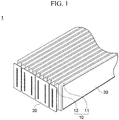
- FIG. 1 is a perspective view of a battery module 1 according to an embodiment of the present invention.
- the battery module 1 may include the plurality of battery cells 10 stacked in a group and one or more bus bars 20 for electrically connecting the plurality of battery cells 10 with each other.
- each of the above-described plurality of battery cells 10 includes a cell body 11 which is configured to house an electrode assembly (not illustrated) therein and is packed in a pouch-shaped sheath (not illustrated) including a resin layer and a metal layer, and electrode tabs 12 drawn from the electrode tab 11.
- each of the above-described one or more bus bars 20 may include a plate 21 having one or more openings 23 formed therein, and a plurality of adjacent electrode tabs 12 among the plurality of electrode tabs 12 may be inserted into any one of the one or more openings 23 formed in the plate 21 to be electrically connected with each other.
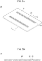
- FIG. 2A is a perspective view illustrating the bus bar 20 according to the embodiment of the present invention
- FIG. 2B is a cross-sectional view taken on line I-I for illustrating the bus bar 20 shown in FIG. 2A
- the bus bar 20 may include protrusions 22.
- the protrusions 22 may be formed on the plate 21 at positions where the openings 23 are formed. By forming the protrusions 22, it is possible to induce an electrode tab group (illustrated in FIG. 3 ) to be inserted into the opening 23, which will be described below.
- the plate 21 is configured in such a way that a width of a space, in which the electrode tab group 13 is introduced from one side (a lower side in FIG. 2 ) of the plate 21, is decreased toward the opening 23.
- the bus bar 20 may include one or more openings 23 formed by penetrating at least a part of the plate 21 in a thickness direction.
- the opening 23 may be longitudinally formed in a slit shape.
- the adjacent electrode tabs 12 may be easily inserted into the slit-shaped opening 23 with being in contact with each other.
- the plurality of electrode tabs 12 inserted into the opening 23 and the bus bar 20 may be electrically connected with each other in a subsequent bonding process such as welding.
- the above-described one or more bus bars 20 may include at least two openings 23 formed in a portion thereof. Thereby, at least four battery cells 10 may be electrically connected with each other through the two opening 23 of one bus bar 20.
- the electrical connection relationship between the bus bar 20 and the plurality of battery cells 10 will be described below.
- the at least two openings 23 may be formed in the plate 21 with a predetermined interval.
- the predetermined interval may be determined based on the number of the battery cells 10 to be connected. That is, when electrically connecting four battery cells 10 by one bus bar 20, the interval between two openings 23 formed in the plate 21 may be determined based on a total thickness of the four battery cells 10 with being stacked in a group. It will be obviously appreciated to those skilled in the art that the distance between the openings 23 may vary based on the width of one battery cell 10.
- FIG. 3 is a schematic view illustrating a plurality of adjacent battery cells 10 among the plurality of battery cells 10 according to the embodiment of the present invention.
- the battery cell 10 may include the cell body 11 and the electrode tab 12 drawn from the cell body 11.
- the electrode tab 12 may include a terrace portion 12a formed by bonding the sheath along a side edge from which the electrode tab 12 is extended in the electrode assembly, an insulation portion 12b continued from the terrace portion 12a to increase sealing properties of the sheath and secure an electrical insulation state, is extended at a position where the electrode tab 12 is drawn from the terrace portion 12a, and an electrode tab portion 12c whose one end is continued from the insulation portion 12b and at least a part of the other end portion is inserted into the opening 23.
- the above-described electrode tabs 12 may include a first bent part 121 formed by bending at least a part thereof in each of the electrode tabs 12 in one direction, and a second bent part 123 formed by bending at least a part of the remaining section thereof in each of the electrode tabs 12 in a direction different from the one direction. That is, the first bent part 121 and the second bent part 123 may be formed by bending in opposite directions to each other.
- the second bent part 123 when bending the first bent part 121 in a clockwise direction, the second bent part 123 may be formed by bending in a counterclockwise direction, and when bending the first bent part 121 in the counterclockwise direction, the second bent part 123 may be formed by bending in the clockwise.
- each of the electrode tabs 12 drawn from the adjacent battery cells 10 among the plurality of battery cells 10 are positioned while at least a part of end portions thereof coming into contact with each other, so as to form the electrode tab group 13.
- each of the electrode tabs 12 may include the first bent part 121 and the second bent part 123.
- the directions in which the first bent part 121 and the second bent part 123 are formed in the plurality of adjacent electrode tabs 12 are different from each other.
- a pair of the adjacent electrode tabs 12 may come into contact with each other while facing each other.
- the first bent part 121 may be formed by bending the electrode tab portion 12c continued from the insulation portion 12b, but it is not limited thereto, and the first bent part 121 may be formed in a section of the insulation portion 12b by bending the insulation portion 12b of the electrode tab 12. As described above, since the bent part is formed in the insulation portion 12b, a volume occupied by the electrode tab 12 in the battery module 1 may be minimized.
- the volume occupied by the electrode tabs 12 in the battery module 1 may be reduced while maintaining an insulation performance of the insulation portion 12b. Thereby, as a total volume of the battery module 1 is reduced, an energy density of the battery module 1 may be increased.
- each of the first bent part 121 and the second bent part 123 may be bent at angles ⁇ 1 and ⁇ 2 similar to each other, and preferably, may be bent at angles ⁇ 1 and ⁇ 2 of 80 to 90 degrees.
- the first bent part 121 and the second bent part 123 may be bent in opposite directions to each other.
- the end portions of the electrode tabs 12 inserted into the opening 23 may be positioned at a substantially right angle with respect to the plate 21, and the plurality of adjacent electrode tabs 12 may be easily inserted into the opening 23 of the bus bar 20.
- first bent part 121 and the second bent part 123 are formed at angles ⁇ 1 and ⁇ 2 of 80 to 90, a jig 40 may be easily inserted during a laser welding process to be described below.
- the laser welding process will be described in detail below with reference to FIG. 9 .
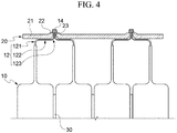
- FIG. 4 is a cross-sectional view illustrating a state in which two electrode tabs 12 are inserted into and fixed to the opening 23 of the bus bar 20 according to the embodiment of the present invention
- FIG. 5 is a cross-sectional view illustrating a state in which three electrode tabs 12 are inserted into and fixed to the opening 23 of the bus bar 20 according to the embodiment of the present invention.
- a plurality of adjacent electrode tabs 12 among the plurality of electrode tabs 12 may be inserted into any one of one or more openings 23 formed in the bus bar 20.
- each of electrode tab groups 13 including the plurality of adjacent electrode tabs 12 among the plurality of electrode tabs 12 may be positioned with being inserted into one or more openings 23 formed in the bus bar 20 respectively corresponding thereto.
- an electrode tab group 13 including two electrode tabs 12, which are positioned adjacent to each other among four electrode tabs 12 located at one side of the battery cell 10 while at least a part of the end portions thereof coming into contact with each other by the first bent part 121 and the second bent part 123, may be positioned with being inserted into any one of one or more openings 23 of the bus bar 20.
- two electrode tab groups 13 may be positioned with being inserted into the openings 23 of the bus bar 20 respectively corresponding thereto.
- three adjacent electrode tabs 12 of the plurality of battery cells 10 are positioned with being inserted into any one of one or more openings 23 of the bus bar 20 while at least a part of each of the electrode tabs 12 coming into contact with each other. That is, since three battery cells 10 may be electrically connected with each other by a single bonding process, a production speed in manufacturing processes of the battery module 1 may be greatly increased.
- the battery module 1 is not limited thereto, and any configuration may be used so long as the plurality of electrode tabs 12 adjacent to each other can be inserted into and fixed to one opening 23 of the bus bar 20, for example, the electrode tabs 12 of four battery cells 10 are inserted into and bonded to one opening 23 of the bus bar 20.
- each of the electrode tabs 12 may include a seat portion 122 between the first bent part 121 and the second bent part 123, and the bus bar 20 may be supported with being placed on the seat portion 122.
- the seat portion 122 between the first bent part 121 and the second bent part 123 may be positioned in parallel to the plate 21 of the bus bar 20, and the bus bar 20 is placed on the seat portion 122 included in the electrode tab 12, thus to come into plane contact with at least a part of the electrode tab 12.
- the bus bar 20 is supported by the electrode tab 12 while coming into plane contact with the seat portion 122 thereof. Therefore, even if an external impact or the like is applied thereto, the connection structure between the bus bar 20 and the electrode tab 12 is rarely damaged, such that durability of the battery module 1 may be increased.
- elastic members 30 may be installed between the plurality of battery cells 10.
- the above-described elastic member 30 may buffer swelling of the battery cell 10 due to thermal expansion, and may prevent the external impact and vibration from being transmitted to the battery cell 10.
- the elastic member 30 is not limited to the configuration of being disposed between the battery cells 10, but may be disposed between two bundles of the battery cells 10, or between three bundles of the battery cells 10, for example, by selecting the number of the battery cells 10, as necessary.
- the battery cells 10 may be connected with each other in various ways, for example, all four electrode tabs 12 are positioned with electrodes having the same polarity as each other, such that four battery cells 10 may be connected in parallel to each other, or otherwise, two electrode tabs 12 in one electrode tab group 13 may be positioned with electrodes having the same polarity as each other to be connected in parallel to each other, and two electrode tab groups 13 including the two electrode tabs 12 may be positioned with electrodes having different polarities from each other to be connected in series.
- a plurality of openings 23 may be formed in one bus bar 20, and a plurality of battery cells 10 connected to the bus bar 20 may be connected in various ways such as a parallel or series connection. Therefore, the plurality of battery cells 10 may be electrically connected with each other in various ways by a user as necessary, without changing the shape of the bus bar 20.
- beads 14 may be formed at the end portions of the plurality of adjacent electrode tabs 12 inserted into the opening 23 of the bus bar 20 according to the embodiment of the present invention during a bonding process such as welding. Thereby, the electrode tab group 13 and the bus bar 20 are connected with each other, and the plurality of battery cells 10 may be electrically connected with each other through the beads 14.
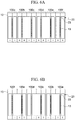
- FIG. 6A is a front view illustrating an electrical connection state of the battery module 1 according to the embodiment of the present invention
- FIG. 6B is a rear view illustrating the electrical connection state of the battery module 1 according to the embodiment of the present invention (that is, the battery cell 10 at a left end of FIG. 6A corresponds to the battery cell 10 at a right end of FIG. 6B ) .
- two or more battery cells 10 may be connected in parallel to each other through the bus bar 20 to form one parallel assembly.
- the battery module 1 may be formed by providing a plurality of parallel assemblies and connecting in series with each other.
- FIG. 6A when viewed from the front, two negative (-) poles of the two leftmost battery cells are connected in parallel by the bus bar 20 to form one parallel assembly 100a. Then, the above-described parallel assembly 100a may be arranged side by side and connected in series with an adjacent parallel assembly 100b having two positive (+) poles connected in parallel therein.
- six parallel assemblies 100a, 100b, 100c, 100d, 100e, and 100f having electrodes of different polarities from each other based on one direction of the plurality of battery cells 10 may be provided and connected in series with each other by the plurality of bus bars 20. That is, a total of 12 battery cells 10 may be electrically connected with each other.
- this configuration is illustrated as an example, and it is not limited thereto.
- three battery cells 10 may be connected in parallel with electrodes having the same polarity as each other to form one parallel assembly (not illustrated), and a plurality of parallel assemblies may be provided and connected in series with each other.
- the number of the battery cells 10 to be connected to one bus bar 20 may freely selected, and the number of the battery cells connected parallel and the number of the battery cells connected in series by the bus bar 20 among the plurality of battery cells 10 may be freely selected. Therefore, a degree of freedom in the configuration of the battery module 11 may be improved.
- FIG. 7 is a perspective view illustrating one side of the battery module 1 according to the embodiment of the present invention.
- the battery module 1 according to the embodiment of the present invention may further include a bus bar cover 200 located outside the one or more bus bars 20 and configured to surround the bus bars 20.
- the bus bar cover 200 may be located in a shape to cover the outside of at least one bus bar 20, such that the bus bar 20 may be protected from external foreign matters and the like.
- the bus bar cover 200 may be made of an insulation material, thereby minimizing the possibility of electrical communication with an external object of the bus bar 20 connected to the plurality of battery cells 10.
- bus bar cover 200 may be coupled with the plurality of bus bars 20, thereby it is possible to fix and support a position between the bus bars 20 in place.
- the bus bar cover 200 and the plurality of bus bars 20 may be connected with each other by a fusion method such as welding or the like, but it is not limited thereto. Any configuration may be used so long as the bus bar cover 200 and the plurality of bus bars 20 can be coupled to each other, for example, a rear surface of the bus bar cover 200 is formed corresponding to the shape of the plurality of bus bars 20, and locking parts (not illustrated) having a predetermined elasticity are formed on at least a part thereof, such that the plurality of bus bars 20 are fastened to the bus bar cover 200 through the locking parts.
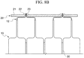
- FIG. 8A is a cross-sectional view illustrating a state in which a bus bar 20 comes in contact with a plurality of stacked battery cells 10 according to another embodiment of the present invention
- FIG. 8B is a cross-sectional view illustrating a state in which the bus bar 20 is placed on the plurality of electrode tabs 12 according to another embodiment of the present invention.
- a plurality of battery cells 10 are stacked, and a plurality of electrode tabs 12 of the adjacent battery cells 10 among the plurality of battery cells 10 come into contact with each other, then the plurality of adjacent electrode tabs 12 may be inserted into any one of one or more openings 23 on one side of the plate 21 in which one or more openings 23 are formed.
- a plurality of battery cells 10 which include the electrode tabs 12 respectively may be stacked. At this time, a plurality of adjacent electrode tabs 12 among the plurality of electrode tabs 12 come into contact with each other to form an electrode tab group 13.
- each of the plurality of electrode tabs 12 may be bent in one direction, and at least a part of the remaining section of the electrode tab 12 may be bent in the direction different from the one direction.
- a first bent part 121 and a second bent part 123 may be formed.
- each of the plurality of adjacent electrode tabs 12 may be formed in a shape of facing each other while at least a part thereof coming into contact with each other.
- each of the electrode tabs 12 may be bent at an angle of 80 to 90 degrees.
- the bus bar 20 may be easily placed on the electrode tabs 12, and the jig 40 may be easily inserted before the bonding process such as welding.
- one or more bus bars 20 including the plate 21 having one or more openings 23 formed therein may be moved to the plurality of stacked battery cells 10 side, and then may be placed on the plurality of electrode tabs, as illustrated in FIG. 8B .
- each of the electrode tab groups 13 including a plurality of adjacent electrode tabs 12 among the electrode tabs 12 may be inserted into each of one or more openings 23 of the bus bar 20 respectively corresponding thereto.
- the electrode tab groups 13 in a state in which the plurality of adjacent electrode tabs 12 are in contact with each other may be disposed so as to protrude outward from the bus bar 20. Thereby, a worker may visually confirm the welding position and easily check the welded portion 132 during the subsequent bonding process such as welding or the like.
- the bus bar 20 may be placed and positioned on the seat portion 122 between the first bent part 121 and the second bent part 123 of the electrode tab 12, the position thereof can be supported between the welding processes, and a working error, which may be caused by a variation of the position of the bus bar 20 between the bonding processes such as welding, can be minimized.
- the electrode tab 12 is bent and positioned. Therefore, a distance between the end portion of the electrode tab 12 at which welding is performed and a portion from which the electrode tab 12 is drawn in the battery cell 10 may be increased, as compared to a case in which the electrode tab 12 is simply positioned perpendicular to the bus bar 20 without being bent. Thereby, a damage to the temperature-sensitive battery cell 10 may be prevented during the bonding process such as welding or the like.
- a laser beam (illustrated in FIG. 9B ) is directly irradiated into a gap between the electrode tabs 12 and the protrusion 22 of the bus bar 20, thereby it is possible to prevent the laser beam from reaching the cell body 11, and minimize restrictions such as irradiating a laser beam L at an inclined angle with respect to a direction in which the electrode tabs 12 protrude during welding. Therefore, the production speed in the manufacturing processes of the battery module 1 may be improved to minimize a welding error.
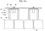
- FIG. 9A is a cross-sectional view illustrating a state in which the jig 40 is inserted between the bus bar 20 and cell bodies 11 according to another embodiment of the present invention
- FIG. 9B is a cross-sectional view illustrating a state in which the electrode tab group 13 inserted into the opening 23 of the bus bar 20 is irradiated with the laser beam L.
- the jig 40 may be inserted between the bus bar 20 and the plurality of battery cells 10. Meanwhile, as described above, since the first bent part 121 and the second bent part 123 of the electrode tab 12 are formed at an angle of 80 to 90 degrees, the jig 40 may be easily inserted between the seat portion 122 of the electrode tab 12 and the cell bodies 11.
- the jig 40 may be inserted into the space between the seat portion 122 of the plurality of adjacent electrode tabs 12 and the cell bodies 11, and the jig 40 may be positioned below the electrode tab group 13 in a direction in which the laser beam L is irradiated during laser welding, which will be described below, such that it is possible to prevent risks such as explosion, fire, and the like, which may be caused by directly irradiating the cell bodies 11 with the laser beam L due to excessive irradiation of the laser beam L.
- the bus bar 20 and the plurality of adjacent electrode tabs 12 may be connected with each other by laser welding.
- the laser beam L may be irradiated in a direction perpendicular to the plate 21 of the bus bar 20.
- the worker may simply irradiate the laser beam L toward at least a part of the electrode tab group 13 protruding outside the bus bar 20 on the upper side of the bus bar 20, and there is no particular limit in the process such as a need to irradiate the laser beam L obliquely to the direction in which the electrode tabs 12 protrude. Therefore, the working speed and accuracy between the welding processes may be greatly improved.
- three or more adjacent electrode tabs 12 may be inserted into and fixed to one opening 23 with being in contact with each other, and may be electrically connected to the bus bar 20 through welding or the like, which are the same as the above-described configuration, and therefore will not be described in detail.
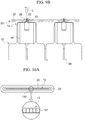
- FIGS. 10A and 10B are cross-sectional views and partial enlarged views illustrating a state in which the electrode tab group 13 is subjected to laser welding according to another embodiment of the present invention.
- the above-described laser welding may be performed with a predetermined interval on end faces of the electrode tabs included in the electrode tab group 13.
- the laser beam L is repeatedly irradiated in a circular pattern without being irradiated in a straight line, and centers of circles formed by the laser beam may be arranged along a longitudinal axis 131 of the end faces of the electrode tabs included in the electrode tab group 13.
- a welding part 132 of the electrode tab group 13 may be uniformly melted through wobble type welding of a pattern in which circulars are repeatedly formed and overlapped with each other, and in particular, which may be effectively applied to precision welding. Thereby, it is possible to improve the stability in the manufacturing process of the battery module 1 during the welding process for the electrode tab 12 included in the battery cell 10 which is vulnerable to high temperature.
- the end faces of the electrode tabs included in the electrode tab group 13 may be continuously irradiated with the laser beam L, and thereby the welding part 132 may be formed in a straight continuous shape.
- the laser beam L is irradiated in a circular pattern, at least a part of the electrode tab group 13 protruding outside the bus bar 20 is melted, such that the above-described beads 14 may be formed, as well as the bus bar 20 and the plurality of adjacent electrode tabs 12 are bonded to each other, such that the plurality of battery cells 10 may be electrically connected with each other.
Landscapes
- Chemical & Material Sciences (AREA)
- Chemical Kinetics & Catalysis (AREA)
- Electrochemistry (AREA)
- General Chemical & Material Sciences (AREA)
- Engineering & Computer Science (AREA)
- Physics & Mathematics (AREA)
- Optics & Photonics (AREA)
- Plasma & Fusion (AREA)
- Mechanical Engineering (AREA)
- Manufacturing & Machinery (AREA)
- Connection Of Batteries Or Terminals (AREA)
- Battery Mounting, Suspending (AREA)
Applications Claiming Priority (1)
| Application Number | Priority Date | Filing Date | Title |
|---|---|---|---|
| KR1020180026475A KR102598811B1 (ko) | 2018-03-06 | 2018-03-06 | 배터리 모듈 및 이의 제조방법 |
Publications (2)
| Publication Number | Publication Date |
|---|---|
| EP3537504A1 true EP3537504A1 (de) | 2019-09-11 |
| EP3537504B1 EP3537504B1 (de) | 2024-07-03 |
Family
ID=65717925
Family Applications (1)
| Application Number | Title | Priority Date | Filing Date |
|---|---|---|---|
| EP19161077.3A Active EP3537504B1 (de) | 2018-03-06 | 2019-03-06 | Batteriemodul und herstellungsverfahren dafür |
Country Status (5)
| Country | Link |
|---|---|
| US (2) | US11691220B2 (de) |
| EP (1) | EP3537504B1 (de) |
| KR (2) | KR102598811B1 (de) |
| CN (2) | CN110233231A (de) |
| HU (1) | HUE068338T2 (de) |
Cited By (4)
| Publication number | Priority date | Publication date | Assignee | Title |
|---|---|---|---|---|
| CN111063854A (zh) * | 2019-12-19 | 2020-04-24 | 双登集团股份有限公司 | 软包电池模组及软包电池模组极耳的激光焊接方法 |
| EP3916825A4 (de) * | 2019-11-14 | 2023-04-05 | LG Energy Solution, Ltd. | Batteriemodul, verfahren zur herstellung eines batteriemoduls und batteriepack mit einem batteriemodul |
| CN117117438A (zh) * | 2023-09-13 | 2023-11-24 | 中联重科股份有限公司 | 一种电池模组及其组装方法 |
| EP4064448A4 (de) * | 2019-11-20 | 2024-01-17 | SK On Co., Ltd. | Batteriemodul |
Families Citing this family (12)
| Publication number | Priority date | Publication date | Assignee | Title |
|---|---|---|---|---|
| KR102258177B1 (ko) * | 2018-09-20 | 2021-05-28 | 주식회사 엘지에너지솔루션 | 배터리 모듈, 이러한 배터리 모듈을 포함하는 배터리 팩 및 이러한 배터리 팩을 포함하는 자동차 |
| US11437666B2 (en) * | 2019-07-31 | 2022-09-06 | Karma Automotive Llc | Battery module including side pressure plates and pouch cell modules |
| KR102861724B1 (ko) * | 2020-07-21 | 2025-09-17 | 주식회사 엘지에너지솔루션 | 개선된 전극 리드 연결 구조를 갖는 배터리 모듈, 그리고 이를 포함하는 배터리 팩 및 자동차 |
| CN112713365B (zh) * | 2020-12-28 | 2022-09-23 | 东莞新能安科技有限公司 | 电池组及用电设备 |
| JP7594919B2 (ja) * | 2021-01-15 | 2024-12-05 | 株式会社Aescジャパン | バッテリーモジュールおよびその製造方法 |
| KR20220126131A (ko) * | 2021-03-08 | 2022-09-15 | 현대자동차주식회사 | 배터리 모듈 및 이의 제조 방법 |
| JP7662271B2 (ja) * | 2021-03-29 | 2025-04-15 | エルジー エナジー ソリューション リミテッド | 電池モジュールおよびこれを含む電池パック |
| JP2024138573A (ja) * | 2021-08-26 | 2024-10-09 | Fdk株式会社 | 電池モジュール、及び当該電池モジュールの製造方法 |
| US20240079681A1 (en) * | 2022-09-02 | 2024-03-07 | Ford Global Technologies, Llc | Multifunctional cross-member beams for traction battery packs |
| KR20240128468A (ko) * | 2023-02-17 | 2024-08-26 | 에스케이온 주식회사 | 배터리 셀, 배터리모듈 및 배터리모듈의 제조방법 |
| KR20240128476A (ko) | 2023-02-17 | 2024-08-26 | 에스케이온 주식회사 | 배터리모듈 및 배터리모듈의 제조방법 |
| JP7841503B2 (ja) * | 2023-08-08 | 2026-04-07 | トヨタ自動車株式会社 | 電池モジュール |
Citations (2)
| Publication number | Priority date | Publication date | Assignee | Title |
|---|---|---|---|---|
| JP2007109548A (ja) * | 2005-10-14 | 2007-04-26 | Nec Corp | 電気デバイス集合体及びその製造方法 |
| KR20150110078A (ko) | 2014-03-24 | 2015-10-02 | 에스케이배터리시스템즈 주식회사 | 버스바 |
Family Cites Families (15)
| Publication number | Priority date | Publication date | Assignee | Title |
|---|---|---|---|---|
| JPS4829587B1 (de) | 1968-03-04 | 1973-09-11 | ||
| KR20080077424A (ko) * | 2007-02-20 | 2008-08-25 | 삼성에스디아이 주식회사 | 이차전지 및 그 제조방법 |
| KR20130131658A (ko) * | 2012-05-24 | 2013-12-04 | 에스케이이노베이션 주식회사 | 이차 전지용 레이저 용접 지그 및 그 용접 방법 |
| KR102140212B1 (ko) | 2014-02-07 | 2020-07-31 | 삼성에스디아이 주식회사 | 배터리모듈 및 그 제조방법 |
| KR101654101B1 (ko) | 2014-03-10 | 2016-09-06 | 세방전지(주) | 초음파 융착장치의 전지탭 고정치구 |
| KR101821378B1 (ko) * | 2014-03-31 | 2018-01-23 | 주식회사 엘지화학 | 전극 리드와 버스바 사이의 결합력 및 공정성이 향상된 배터리 모듈 및 이를 포함하는 배터리 팩 |
| KR101722662B1 (ko) * | 2014-10-02 | 2017-04-03 | 에스케이이노베이션 주식회사 | 파우치형 이차 전지 |
| KR101834506B1 (ko) * | 2015-03-27 | 2018-03-05 | 주식회사 엘지화학 | 전지 모듈 |
| US10751835B2 (en) * | 2015-06-19 | 2020-08-25 | Ipg Photonics Corporation | Laser welding head with dual movable mirrors providing beam movement and laser welding systems and methods using same |
| WO2016206756A1 (en) * | 2015-06-26 | 2016-12-29 | Toyota Motor Europe Nv/Sa | Systems and methods for laser welding |
| KR102056875B1 (ko) | 2015-11-10 | 2019-12-17 | 주식회사 엘지화학 | 배터리 모듈 및 이를 포함하는 배터리 팩 |
| CN205194790U (zh) * | 2015-12-01 | 2016-04-27 | 浙江超威创元实业有限公司 | 一种便于自动组装的动力电池模组及电动车 |
| CN206250272U (zh) * | 2016-12-02 | 2017-06-13 | 宁德时代新能源科技股份有限公司 | 二次电池 |
| US11088410B2 (en) * | 2016-12-23 | 2021-08-10 | Sk Innovation Co., Ltd. | Battery module |
| CN107552958A (zh) * | 2017-08-03 | 2018-01-09 | 大族激光科技产业集团股份有限公司 | 一种动力电池封口的焊接方法 |
-
2018
- 2018-03-06 KR KR1020180026475A patent/KR102598811B1/ko active Active
-
2019
- 2019-03-06 EP EP19161077.3A patent/EP3537504B1/de active Active
- 2019-03-06 HU HUE19161077A patent/HUE068338T2/hu unknown
- 2019-03-06 CN CN201910166451.5A patent/CN110233231A/zh active Pending
- 2019-03-06 CN CN202410549009.1A patent/CN118367309A/zh active Pending
- 2019-03-06 US US16/294,354 patent/US11691220B2/en active Active
-
2023
- 2023-05-16 US US18/197,735 patent/US12172231B2/en active Active
- 2023-11-01 KR KR1020230148996A patent/KR102780607B1/ko active Active
Patent Citations (2)
| Publication number | Priority date | Publication date | Assignee | Title |
|---|---|---|---|---|
| JP2007109548A (ja) * | 2005-10-14 | 2007-04-26 | Nec Corp | 電気デバイス集合体及びその製造方法 |
| KR20150110078A (ko) | 2014-03-24 | 2015-10-02 | 에스케이배터리시스템즈 주식회사 | 버스바 |
Cited By (6)
| Publication number | Priority date | Publication date | Assignee | Title |
|---|---|---|---|---|
| EP3916825A4 (de) * | 2019-11-14 | 2023-04-05 | LG Energy Solution, Ltd. | Batteriemodul, verfahren zur herstellung eines batteriemoduls und batteriepack mit einem batteriemodul |
| US12266824B2 (en) | 2019-11-14 | 2025-04-01 | Lg Energy Solution, Ltd. | Battery module, method of manufacturing battery module and battery pack including battery module |
| EP4064448A4 (de) * | 2019-11-20 | 2024-01-17 | SK On Co., Ltd. | Batteriemodul |
| US12603393B2 (en) | 2019-11-20 | 2026-04-14 | Sk On Co., Ltd. | Battery module |
| CN111063854A (zh) * | 2019-12-19 | 2020-04-24 | 双登集团股份有限公司 | 软包电池模组及软包电池模组极耳的激光焊接方法 |
| CN117117438A (zh) * | 2023-09-13 | 2023-11-24 | 中联重科股份有限公司 | 一种电池模组及其组装方法 |
Also Published As
| Publication number | Publication date |
|---|---|
| KR102598811B1 (ko) | 2023-11-03 |
| CN110233231A (zh) | 2019-09-13 |
| KR102780607B1 (ko) | 2025-03-11 |
| US20230278138A1 (en) | 2023-09-07 |
| KR20230155394A (ko) | 2023-11-10 |
| US20190280279A1 (en) | 2019-09-12 |
| US12172231B2 (en) | 2024-12-24 |
| KR20190105856A (ko) | 2019-09-18 |
| EP3537504B1 (de) | 2024-07-03 |
| CN118367309A (zh) | 2024-07-19 |
| US11691220B2 (en) | 2023-07-04 |
| HUE068338T2 (hu) | 2024-12-28 |
Similar Documents
| Publication | Publication Date | Title |
|---|---|---|
| EP3537504B1 (de) | Batteriemodul und herstellungsverfahren dafür | |
| KR102299512B1 (ko) | 배터리 모듈 | |
| US11670795B2 (en) | Battery module | |
| US10084173B2 (en) | Battery pack | |
| EP1812982B1 (de) | Sekundärbatteriepack mit anordnung zu alternativer ausrichtung | |
| EP3799155B1 (de) | Batteriemodul, batteriepack mit dem batteriemodul und fahrzeug mit dem batteriepack | |
| EP3926734B1 (de) | Batteriemodul und batteriepack damit | |
| EP3754771A1 (de) | Elektrodenanordnung und sekundärbatterie damit | |
| KR20100067464A (ko) | 전지 모듈 | |
| US12183952B2 (en) | Battery pack with enhanced structure for preventing short circuit and shock | |
| EP3971925B1 (de) | Batteriemodul und batteriepack damit | |
| US11552360B2 (en) | Cartridge and battery module comprising same | |
| US11901589B2 (en) | Cylindrical secondary battery module | |
| KR101913375B1 (ko) | 배터리 모듈 | |
| KR102834168B1 (ko) | 내충격성이 향상된 전극 리드를 포함하는 전지 셀 어셈블리 및 이의 제조방법 | |
| CN115136397A (zh) | 电池组和包括该电池组的装置 | |
| KR102167430B1 (ko) | 배터리 팩 | |
| KR20240156286A (ko) | 이차 전지 | |
| KR20210103089A (ko) | 무용접 방식으로 고정이 가능한 전지 셀 및 이를 포함하는 전지 팩 | |
| KR20210011690A (ko) | 전류 차단 기능이 구비된 전지 모듈 및 이를 포함하는 디바이스 |
Legal Events
| Date | Code | Title | Description |
|---|---|---|---|
| PUAI | Public reference made under article 153(3) epc to a published international application that has entered the european phase |
Free format text: ORIGINAL CODE: 0009012 |
|
| STAA | Information on the status of an ep patent application or granted ep patent |
Free format text: STATUS: REQUEST FOR EXAMINATION WAS MADE |
|
| 17P | Request for examination filed |
Effective date: 20190306 |
|
| AK | Designated contracting states |
Kind code of ref document: A1 Designated state(s): AL AT BE BG CH CY CZ DE DK EE ES FI FR GB GR HR HU IE IS IT LI LT LU LV MC MK MT NL NO PL PT RO RS SE SI SK SM TR |
|
| AX | Request for extension of the european patent |
Extension state: BA ME |
|
| TPAC | Observations filed by third parties |
Free format text: ORIGINAL CODE: EPIDOSNTIPA |
|
| STAA | Information on the status of an ep patent application or granted ep patent |
Free format text: STATUS: EXAMINATION IS IN PROGRESS |
|
| 17Q | First examination report despatched |
Effective date: 20220615 |
|
| RAP1 | Party data changed (applicant data changed or rights of an application transferred) |
Owner name: SK ON CO., LTD. |
|
| P01 | Opt-out of the competence of the unified patent court (upc) registered |
Effective date: 20230602 |
|
| REG | Reference to a national code |
Free format text: PREVIOUS MAIN CLASS: H01M0002200000 Ipc: H01M0050211000 Ref country code: DE Ref legal event code: R079 Ref document number: 602019054453 Country of ref document: DE Free format text: PREVIOUS MAIN CLASS: H01M0002200000 Ipc: H01M0050211000 |
|
| GRAP | Despatch of communication of intention to grant a patent |
Free format text: ORIGINAL CODE: EPIDOSNIGR1 |
|
| STAA | Information on the status of an ep patent application or granted ep patent |
Free format text: STATUS: GRANT OF PATENT IS INTENDED |
|
| RIC1 | Information provided on ipc code assigned before grant |
Ipc: H01M 10/058 20100101ALI20240102BHEP Ipc: H01M 50/553 20210101ALI20240102BHEP Ipc: H01M 50/516 20210101ALI20240102BHEP Ipc: H01M 50/512 20210101ALI20240102BHEP Ipc: H01M 50/505 20210101ALI20240102BHEP Ipc: H01M 50/50 20210101ALI20240102BHEP Ipc: H01M 50/211 20210101AFI20240102BHEP |
|
| INTG | Intention to grant announced |
Effective date: 20240125 |
|
| GRAS | Grant fee paid |
Free format text: ORIGINAL CODE: EPIDOSNIGR3 |
|
| GRAA | (expected) grant |
Free format text: ORIGINAL CODE: 0009210 |
|
| STAA | Information on the status of an ep patent application or granted ep patent |
Free format text: STATUS: THE PATENT HAS BEEN GRANTED |
|
| AK | Designated contracting states |
Kind code of ref document: B1 Designated state(s): AL AT BE BG CH CY CZ DE DK EE ES FI FR GB GR HR HU IE IS IT LI LT LU LV MC MK MT NL NO PL PT RO RS SE SI SK SM TR |
|
| REG | Reference to a national code |
Ref country code: CH Ref legal event code: EP |
|
| REG | Reference to a national code |
Ref country code: DE Ref legal event code: R096 Ref document number: 602019054453 Country of ref document: DE |
|
| REG | Reference to a national code |
Ref country code: LT Ref legal event code: MG9D |
|
| REG | Reference to a national code |
Ref country code: NL Ref legal event code: MP Effective date: 20240703 |
|
| PG25 | Lapsed in a contracting state [announced via postgrant information from national office to epo] |
Ref country code: PT Free format text: LAPSE BECAUSE OF FAILURE TO SUBMIT A TRANSLATION OF THE DESCRIPTION OR TO PAY THE FEE WITHIN THE PRESCRIBED TIME-LIMIT Effective date: 20241104 |
|
| REG | Reference to a national code |
Ref country code: AT Ref legal event code: MK05 Ref document number: 1700796 Country of ref document: AT Kind code of ref document: T Effective date: 20240703 |
|
| PG25 | Lapsed in a contracting state [announced via postgrant information from national office to epo] |
Ref country code: NL Free format text: LAPSE BECAUSE OF FAILURE TO SUBMIT A TRANSLATION OF THE DESCRIPTION OR TO PAY THE FEE WITHIN THE PRESCRIBED TIME-LIMIT Effective date: 20240703 |
|
| REG | Reference to a national code |
Ref country code: HU Ref legal event code: AG4A Ref document number: E068338 Country of ref document: HU |
|
| PG25 | Lapsed in a contracting state [announced via postgrant information from national office to epo] |
Ref country code: PT Free format text: LAPSE BECAUSE OF FAILURE TO SUBMIT A TRANSLATION OF THE DESCRIPTION OR TO PAY THE FEE WITHIN THE PRESCRIBED TIME-LIMIT Effective date: 20241104 Ref country code: NL Free format text: LAPSE BECAUSE OF FAILURE TO SUBMIT A TRANSLATION OF THE DESCRIPTION OR TO PAY THE FEE WITHIN THE PRESCRIBED TIME-LIMIT Effective date: 20240703 |
|
| PG25 | Lapsed in a contracting state [announced via postgrant information from national office to epo] |
Ref country code: NO Free format text: LAPSE BECAUSE OF FAILURE TO SUBMIT A TRANSLATION OF THE DESCRIPTION OR TO PAY THE FEE WITHIN THE PRESCRIBED TIME-LIMIT Effective date: 20241003 |
|
| PG25 | Lapsed in a contracting state [announced via postgrant information from national office to epo] |
Ref country code: FI Free format text: LAPSE BECAUSE OF FAILURE TO SUBMIT A TRANSLATION OF THE DESCRIPTION OR TO PAY THE FEE WITHIN THE PRESCRIBED TIME-LIMIT Effective date: 20240703 Ref country code: GR Free format text: LAPSE BECAUSE OF FAILURE TO SUBMIT A TRANSLATION OF THE DESCRIPTION OR TO PAY THE FEE WITHIN THE PRESCRIBED TIME-LIMIT Effective date: 20241004 Ref country code: PL Free format text: LAPSE BECAUSE OF FAILURE TO SUBMIT A TRANSLATION OF THE DESCRIPTION OR TO PAY THE FEE WITHIN THE PRESCRIBED TIME-LIMIT Effective date: 20240703 |
|
| PG25 | Lapsed in a contracting state [announced via postgrant information from national office to epo] |
Ref country code: BG Free format text: LAPSE BECAUSE OF FAILURE TO SUBMIT A TRANSLATION OF THE DESCRIPTION OR TO PAY THE FEE WITHIN THE PRESCRIBED TIME-LIMIT Effective date: 20240703 |
|
| PG25 | Lapsed in a contracting state [announced via postgrant information from national office to epo] |
Ref country code: LV Free format text: LAPSE BECAUSE OF FAILURE TO SUBMIT A TRANSLATION OF THE DESCRIPTION OR TO PAY THE FEE WITHIN THE PRESCRIBED TIME-LIMIT Effective date: 20240703 |
|
| PG25 | Lapsed in a contracting state [announced via postgrant information from national office to epo] |
Ref country code: AT Free format text: LAPSE BECAUSE OF FAILURE TO SUBMIT A TRANSLATION OF THE DESCRIPTION OR TO PAY THE FEE WITHIN THE PRESCRIBED TIME-LIMIT Effective date: 20240703 Ref country code: IS Free format text: LAPSE BECAUSE OF FAILURE TO SUBMIT A TRANSLATION OF THE DESCRIPTION OR TO PAY THE FEE WITHIN THE PRESCRIBED TIME-LIMIT Effective date: 20241103 |
|
| PG25 | Lapsed in a contracting state [announced via postgrant information from national office to epo] |
Ref country code: CZ Free format text: LAPSE BECAUSE OF FAILURE TO SUBMIT A TRANSLATION OF THE DESCRIPTION OR TO PAY THE FEE WITHIN THE PRESCRIBED TIME-LIMIT Effective date: 20240703 Ref country code: HR Free format text: LAPSE BECAUSE OF FAILURE TO SUBMIT A TRANSLATION OF THE DESCRIPTION OR TO PAY THE FEE WITHIN THE PRESCRIBED TIME-LIMIT Effective date: 20240703 |
|
| PG25 | Lapsed in a contracting state [announced via postgrant information from national office to epo] |
Ref country code: ES Free format text: LAPSE BECAUSE OF FAILURE TO SUBMIT A TRANSLATION OF THE DESCRIPTION OR TO PAY THE FEE WITHIN THE PRESCRIBED TIME-LIMIT Effective date: 20240703 Ref country code: RS Free format text: LAPSE BECAUSE OF FAILURE TO SUBMIT A TRANSLATION OF THE DESCRIPTION OR TO PAY THE FEE WITHIN THE PRESCRIBED TIME-LIMIT Effective date: 20241003 |
|
| PG25 | Lapsed in a contracting state [announced via postgrant information from national office to epo] |
Ref country code: RS Free format text: LAPSE BECAUSE OF FAILURE TO SUBMIT A TRANSLATION OF THE DESCRIPTION OR TO PAY THE FEE WITHIN THE PRESCRIBED TIME-LIMIT Effective date: 20241003 Ref country code: PL Free format text: LAPSE BECAUSE OF FAILURE TO SUBMIT A TRANSLATION OF THE DESCRIPTION OR TO PAY THE FEE WITHIN THE PRESCRIBED TIME-LIMIT Effective date: 20240703 Ref country code: NO Free format text: LAPSE BECAUSE OF FAILURE TO SUBMIT A TRANSLATION OF THE DESCRIPTION OR TO PAY THE FEE WITHIN THE PRESCRIBED TIME-LIMIT Effective date: 20241003 Ref country code: LV Free format text: LAPSE BECAUSE OF FAILURE TO SUBMIT A TRANSLATION OF THE DESCRIPTION OR TO PAY THE FEE WITHIN THE PRESCRIBED TIME-LIMIT Effective date: 20240703 Ref country code: IS Free format text: LAPSE BECAUSE OF FAILURE TO SUBMIT A TRANSLATION OF THE DESCRIPTION OR TO PAY THE FEE WITHIN THE PRESCRIBED TIME-LIMIT Effective date: 20241103 Ref country code: HR Free format text: LAPSE BECAUSE OF FAILURE TO SUBMIT A TRANSLATION OF THE DESCRIPTION OR TO PAY THE FEE WITHIN THE PRESCRIBED TIME-LIMIT Effective date: 20240703 Ref country code: GR Free format text: LAPSE BECAUSE OF FAILURE TO SUBMIT A TRANSLATION OF THE DESCRIPTION OR TO PAY THE FEE WITHIN THE PRESCRIBED TIME-LIMIT Effective date: 20241004 Ref country code: FI Free format text: LAPSE BECAUSE OF FAILURE TO SUBMIT A TRANSLATION OF THE DESCRIPTION OR TO PAY THE FEE WITHIN THE PRESCRIBED TIME-LIMIT Effective date: 20240703 Ref country code: ES Free format text: LAPSE BECAUSE OF FAILURE TO SUBMIT A TRANSLATION OF THE DESCRIPTION OR TO PAY THE FEE WITHIN THE PRESCRIBED TIME-LIMIT Effective date: 20240703 Ref country code: CZ Free format text: LAPSE BECAUSE OF FAILURE TO SUBMIT A TRANSLATION OF THE DESCRIPTION OR TO PAY THE FEE WITHIN THE PRESCRIBED TIME-LIMIT Effective date: 20240703 Ref country code: BG Free format text: LAPSE BECAUSE OF FAILURE TO SUBMIT A TRANSLATION OF THE DESCRIPTION OR TO PAY THE FEE WITHIN THE PRESCRIBED TIME-LIMIT Effective date: 20240703 Ref country code: AT Free format text: LAPSE BECAUSE OF FAILURE TO SUBMIT A TRANSLATION OF THE DESCRIPTION OR TO PAY THE FEE WITHIN THE PRESCRIBED TIME-LIMIT Effective date: 20240703 |
|
| REG | Reference to a national code |
Ref country code: DE Ref legal event code: R097 Ref document number: 602019054453 Country of ref document: DE |
|
| PG25 | Lapsed in a contracting state [announced via postgrant information from national office to epo] |
Ref country code: SM Free format text: LAPSE BECAUSE OF FAILURE TO SUBMIT A TRANSLATION OF THE DESCRIPTION OR TO PAY THE FEE WITHIN THE PRESCRIBED TIME-LIMIT Effective date: 20240703 Ref country code: RO Free format text: LAPSE BECAUSE OF FAILURE TO SUBMIT A TRANSLATION OF THE DESCRIPTION OR TO PAY THE FEE WITHIN THE PRESCRIBED TIME-LIMIT Effective date: 20240703 Ref country code: DK Free format text: LAPSE BECAUSE OF FAILURE TO SUBMIT A TRANSLATION OF THE DESCRIPTION OR TO PAY THE FEE WITHIN THE PRESCRIBED TIME-LIMIT Effective date: 20240703 |
|
| PG25 | Lapsed in a contracting state [announced via postgrant information from national office to epo] |
Ref country code: EE Free format text: LAPSE BECAUSE OF FAILURE TO SUBMIT A TRANSLATION OF THE DESCRIPTION OR TO PAY THE FEE WITHIN THE PRESCRIBED TIME-LIMIT Effective date: 20240703 |
|
| PG25 | Lapsed in a contracting state [announced via postgrant information from national office to epo] |
Ref country code: SK Free format text: LAPSE BECAUSE OF FAILURE TO SUBMIT A TRANSLATION OF THE DESCRIPTION OR TO PAY THE FEE WITHIN THE PRESCRIBED TIME-LIMIT Effective date: 20240703 Ref country code: IT Free format text: LAPSE BECAUSE OF FAILURE TO SUBMIT A TRANSLATION OF THE DESCRIPTION OR TO PAY THE FEE WITHIN THE PRESCRIBED TIME-LIMIT Effective date: 20240703 |
|
| PLBE | No opposition filed within time limit |
Free format text: ORIGINAL CODE: 0009261 |
|
| STAA | Information on the status of an ep patent application or granted ep patent |
Free format text: STATUS: NO OPPOSITION FILED WITHIN TIME LIMIT |
|
| 26N | No opposition filed |
Effective date: 20250404 |
|
| PG25 | Lapsed in a contracting state [announced via postgrant information from national office to epo] |
Ref country code: SE Free format text: LAPSE BECAUSE OF FAILURE TO SUBMIT A TRANSLATION OF THE DESCRIPTION OR TO PAY THE FEE WITHIN THE PRESCRIBED TIME-LIMIT Effective date: 20240703 |
|
| PG25 | Lapsed in a contracting state [announced via postgrant information from national office to epo] |
Ref country code: MC Free format text: LAPSE BECAUSE OF FAILURE TO SUBMIT A TRANSLATION OF THE DESCRIPTION OR TO PAY THE FEE WITHIN THE PRESCRIBED TIME-LIMIT Effective date: 20240703 |
|
| REG | Reference to a national code |
Ref country code: CH Ref legal event code: H13 Free format text: ST27 STATUS EVENT CODE: U-0-0-H10-H13 (AS PROVIDED BY THE NATIONAL OFFICE) Effective date: 20251024 |
|
| PG25 | Lapsed in a contracting state [announced via postgrant information from national office to epo] |
Ref country code: LU Free format text: LAPSE BECAUSE OF NON-PAYMENT OF DUE FEES Effective date: 20250306 |
|
| GBPC | Gb: european patent ceased through non-payment of renewal fee |
Effective date: 20250306 |
|
| REG | Reference to a national code |
Ref country code: BE Ref legal event code: MM Effective date: 20250331 |
|
| PG25 | Lapsed in a contracting state [announced via postgrant information from national office to epo] |
Ref country code: GB Free format text: LAPSE BECAUSE OF NON-PAYMENT OF DUE FEES Effective date: 20250306 |
|
| PG25 | Lapsed in a contracting state [announced via postgrant information from national office to epo] |
Ref country code: FR Free format text: LAPSE BECAUSE OF NON-PAYMENT OF DUE FEES Effective date: 20250331 |
|
| PG25 | Lapsed in a contracting state [announced via postgrant information from national office to epo] |
Ref country code: BE Free format text: LAPSE BECAUSE OF NON-PAYMENT OF DUE FEES Effective date: 20250331 |
|
| PG25 | Lapsed in a contracting state [announced via postgrant information from national office to epo] |
Ref country code: CH Free format text: LAPSE BECAUSE OF NON-PAYMENT OF DUE FEES Effective date: 20250331 |
|
| PG25 | Lapsed in a contracting state [announced via postgrant information from national office to epo] |
Ref country code: IE Free format text: LAPSE BECAUSE OF NON-PAYMENT OF DUE FEES Effective date: 20250306 |
|
| PGFP | Annual fee paid to national office [announced via postgrant information from national office to epo] |
Ref country code: DE Payment date: 20251222 Year of fee payment: 8 |
|
| PGFP | Annual fee paid to national office [announced via postgrant information from national office to epo] |
Ref country code: HU Payment date: 20260129 Year of fee payment: 8 |