EP3537623B1 - Sendevorrichtung, sendeverfahren, empfangsvorrichtung und empfangsverfahren - Google Patents
Sendevorrichtung, sendeverfahren, empfangsvorrichtung und empfangsverfahren Download PDFInfo
- Publication number
- EP3537623B1 EP3537623B1 EP17867427.1A EP17867427A EP3537623B1 EP 3537623 B1 EP3537623 B1 EP 3537623B1 EP 17867427 A EP17867427 A EP 17867427A EP 3537623 B1 EP3537623 B1 EP 3537623B1
- Authority
- EP
- European Patent Office
- Prior art keywords
- signal
- transmission
- symbol
- precoded
- data
- Prior art date
- Legal status (The legal status is an assumption and is not a legal conclusion. Google has not performed a legal analysis and makes no representation as to the accuracy of the status listed.)
- Active
Links
Images





Classifications
-
- H—ELECTRICITY
- H04—ELECTRIC COMMUNICATION TECHNIQUE
- H04B—TRANSMISSION
- H04B7/00—Radio transmission systems, i.e. using radiation field
- H04B7/02—Diversity systems; Multi-antenna system, i.e. transmission or reception using multiple antennas
- H04B7/04—Diversity systems; Multi-antenna system, i.e. transmission or reception using multiple antennas using two or more spaced independent antennas
- H04B7/06—Diversity systems; Multi-antenna system, i.e. transmission or reception using multiple antennas using two or more spaced independent antennas at the transmitting station
- H04B7/0613—Diversity systems; Multi-antenna system, i.e. transmission or reception using multiple antennas using two or more spaced independent antennas at the transmitting station using simultaneous transmission
- H04B7/068—Diversity systems; Multi-antenna system, i.e. transmission or reception using multiple antennas using two or more spaced independent antennas at the transmitting station using simultaneous transmission using space frequency diversity
-
- H—ELECTRICITY
- H04—ELECTRIC COMMUNICATION TECHNIQUE
- H04B—TRANSMISSION
- H04B7/00—Radio transmission systems, i.e. using radiation field
- H04B7/02—Diversity systems; Multi-antenna system, i.e. transmission or reception using multiple antennas
- H04B7/04—Diversity systems; Multi-antenna system, i.e. transmission or reception using multiple antennas using two or more spaced independent antennas
- H04B7/06—Diversity systems; Multi-antenna system, i.e. transmission or reception using multiple antennas using two or more spaced independent antennas at the transmitting station
- H04B7/0613—Diversity systems; Multi-antenna system, i.e. transmission or reception using multiple antennas using two or more spaced independent antennas at the transmitting station using simultaneous transmission
- H04B7/0667—Diversity systems; Multi-antenna system, i.e. transmission or reception using multiple antennas using two or more spaced independent antennas at the transmitting station using simultaneous transmission of delayed versions of same signal
-
- H—ELECTRICITY
- H04—ELECTRIC COMMUNICATION TECHNIQUE
- H04B—TRANSMISSION
- H04B7/00—Radio transmission systems, i.e. using radiation field
- H04B7/02—Diversity systems; Multi-antenna system, i.e. transmission or reception using multiple antennas
- H04B7/04—Diversity systems; Multi-antenna system, i.e. transmission or reception using multiple antennas using two or more spaced independent antennas
- H04B7/0413—MIMO systems
-
- H—ELECTRICITY
- H04—ELECTRIC COMMUNICATION TECHNIQUE
- H04B—TRANSMISSION
- H04B7/00—Radio transmission systems, i.e. using radiation field
- H04B7/02—Diversity systems; Multi-antenna system, i.e. transmission or reception using multiple antennas
- H04B7/04—Diversity systems; Multi-antenna system, i.e. transmission or reception using multiple antennas using two or more spaced independent antennas
- H04B7/06—Diversity systems; Multi-antenna system, i.e. transmission or reception using multiple antennas using two or more spaced independent antennas at the transmitting station
-
- H—ELECTRICITY
- H04—ELECTRIC COMMUNICATION TECHNIQUE
- H04B—TRANSMISSION
- H04B7/00—Radio transmission systems, i.e. using radiation field
- H04B7/02—Diversity systems; Multi-antenna system, i.e. transmission or reception using multiple antennas
- H04B7/04—Diversity systems; Multi-antenna system, i.e. transmission or reception using multiple antennas using two or more spaced independent antennas
- H04B7/06—Diversity systems; Multi-antenna system, i.e. transmission or reception using multiple antennas using two or more spaced independent antennas at the transmitting station
- H04B7/0613—Diversity systems; Multi-antenna system, i.e. transmission or reception using multiple antennas using two or more spaced independent antennas at the transmitting station using simultaneous transmission
- H04B7/0615—Diversity systems; Multi-antenna system, i.e. transmission or reception using multiple antennas using two or more spaced independent antennas at the transmitting station using simultaneous transmission of weighted versions of same signal
- H04B7/0617—Diversity systems; Multi-antenna system, i.e. transmission or reception using multiple antennas using two or more spaced independent antennas at the transmitting station using simultaneous transmission of weighted versions of same signal for beam forming
-
- H—ELECTRICITY
- H04—ELECTRIC COMMUNICATION TECHNIQUE
- H04B—TRANSMISSION
- H04B7/00—Radio transmission systems, i.e. using radiation field
- H04B7/02—Diversity systems; Multi-antenna system, i.e. transmission or reception using multiple antennas
- H04B7/04—Diversity systems; Multi-antenna system, i.e. transmission or reception using multiple antennas using two or more spaced independent antennas
- H04B7/06—Diversity systems; Multi-antenna system, i.e. transmission or reception using multiple antennas using two or more spaced independent antennas at the transmitting station
- H04B7/0613—Diversity systems; Multi-antenna system, i.e. transmission or reception using multiple antennas using two or more spaced independent antennas at the transmitting station using simultaneous transmission
- H04B7/0615—Diversity systems; Multi-antenna system, i.e. transmission or reception using multiple antennas using two or more spaced independent antennas at the transmitting station using simultaneous transmission of weighted versions of same signal
- H04B7/0619—Diversity systems; Multi-antenna system, i.e. transmission or reception using multiple antennas using two or more spaced independent antennas at the transmitting station using simultaneous transmission of weighted versions of same signal using feedback from receiving side
- H04B7/0621—Feedback content
- H04B7/0634—Antenna weights or vector/matrix coefficients
-
- H—ELECTRICITY
- H04—ELECTRIC COMMUNICATION TECHNIQUE
- H04B—TRANSMISSION
- H04B7/00—Radio transmission systems, i.e. using radiation field
- H04B7/02—Diversity systems; Multi-antenna system, i.e. transmission or reception using multiple antennas
- H04B7/04—Diversity systems; Multi-antenna system, i.e. transmission or reception using multiple antennas using two or more spaced independent antennas
- H04B7/06—Diversity systems; Multi-antenna system, i.e. transmission or reception using multiple antennas using two or more spaced independent antennas at the transmitting station
- H04B7/0613—Diversity systems; Multi-antenna system, i.e. transmission or reception using multiple antennas using two or more spaced independent antennas at the transmitting station using simultaneous transmission
- H04B7/0682—Diversity systems; Multi-antenna system, i.e. transmission or reception using multiple antennas using two or more spaced independent antennas at the transmitting station using simultaneous transmission using phase diversity (e.g. phase sweeping)
-
- H—ELECTRICITY
- H04—ELECTRIC COMMUNICATION TECHNIQUE
- H04B—TRANSMISSION
- H04B7/00—Radio transmission systems, i.e. using radiation field
- H04B7/02—Diversity systems; Multi-antenna system, i.e. transmission or reception using multiple antennas
- H04B7/04—Diversity systems; Multi-antenna system, i.e. transmission or reception using multiple antennas using two or more spaced independent antennas
- H04B7/08—Diversity systems; Multi-antenna system, i.e. transmission or reception using multiple antennas using two or more spaced independent antennas at the receiving station
- H04B7/0837—Diversity systems; Multi-antenna system, i.e. transmission or reception using multiple antennas using two or more spaced independent antennas at the receiving station using pre-detection combining
- H04B7/0842—Weighted combining
-
- H—ELECTRICITY
- H04—ELECTRIC COMMUNICATION TECHNIQUE
- H04B—TRANSMISSION
- H04B7/00—Radio transmission systems, i.e. using radiation field
- H04B7/02—Diversity systems; Multi-antenna system, i.e. transmission or reception using multiple antennas
- H04B7/04—Diversity systems; Multi-antenna system, i.e. transmission or reception using multiple antennas using two or more spaced independent antennas
- H04B7/08—Diversity systems; Multi-antenna system, i.e. transmission or reception using multiple antennas using two or more spaced independent antennas at the receiving station
- H04B7/0891—Space-time diversity
-
- H—ELECTRICITY
- H04—ELECTRIC COMMUNICATION TECHNIQUE
- H04B—TRANSMISSION
- H04B7/00—Radio transmission systems, i.e. using radiation field
- H04B7/02—Diversity systems; Multi-antenna system, i.e. transmission or reception using multiple antennas
- H04B7/12—Frequency diversity
-
- H—ELECTRICITY
- H04—ELECTRIC COMMUNICATION TECHNIQUE
- H04L—TRANSMISSION OF DIGITAL INFORMATION, e.g. TELEGRAPHIC COMMUNICATION
- H04L1/00—Arrangements for detecting or preventing errors in the information received
- H04L1/0078—Avoidance of errors by organising the transmitted data in a format specifically designed to deal with errors, e.g. location
-
- H—ELECTRICITY
- H04—ELECTRIC COMMUNICATION TECHNIQUE
- H04L—TRANSMISSION OF DIGITAL INFORMATION, e.g. TELEGRAPHIC COMMUNICATION
- H04L1/00—Arrangements for detecting or preventing errors in the information received
- H04L1/02—Arrangements for detecting or preventing errors in the information received by diversity reception
- H04L1/06—Arrangements for detecting or preventing errors in the information received by diversity reception using space diversity
-
- H—ELECTRICITY
- H04—ELECTRIC COMMUNICATION TECHNIQUE
- H04L—TRANSMISSION OF DIGITAL INFORMATION, e.g. TELEGRAPHIC COMMUNICATION
- H04L27/00—Modulated-carrier systems
- H04L27/26—Systems using multi-frequency codes
- H04L27/2601—Multicarrier modulation systems
- H04L27/2602—Signal structure
- H04L27/2605—Symbol extensions, e.g. Zero Tail, Unique Word [UW]
-
- H—ELECTRICITY
- H04—ELECTRIC COMMUNICATION TECHNIQUE
- H04L—TRANSMISSION OF DIGITAL INFORMATION, e.g. TELEGRAPHIC COMMUNICATION
- H04L27/00—Modulated-carrier systems
- H04L27/26—Systems using multi-frequency codes
- H04L27/2601—Multicarrier modulation systems
- H04L27/2626—Arrangements specific to the transmitter only
- H04L27/2627—Modulators
- H04L27/2634—Inverse fast Fourier transform [IFFT] or inverse discrete Fourier transform [IDFT] modulators in combination with other circuits for modulation
- H04L27/2636—Inverse fast Fourier transform [IFFT] or inverse discrete Fourier transform [IDFT] modulators in combination with other circuits for modulation with FFT or DFT modulators, e.g. standard single-carrier frequency-division multiple access [SC-FDMA] transmitter or DFT spread orthogonal frequency division multiplexing [DFT-SOFDM]
-
- H—ELECTRICITY
- H04—ELECTRIC COMMUNICATION TECHNIQUE
- H04L—TRANSMISSION OF DIGITAL INFORMATION, e.g. TELEGRAPHIC COMMUNICATION
- H04L27/00—Modulated-carrier systems
- H04L27/26—Systems using multi-frequency codes
- H04L27/2601—Multicarrier modulation systems
- H04L27/2626—Arrangements specific to the transmitter only
- H04L27/2627—Modulators
- H04L27/2637—Modulators with direct modulation of individual subcarriers
Definitions
- the present disclosure relates to a transmission apparatus that performs communication using a multiantenna and a transmission method.
- the IEEE802.11 ad standard is one of wireless LAN-related standards and is a standard in terms of wireless communication using a 60 GHz band millimeter wave (NPL 1). In the IEEE802.11ad standard, transmission using a single carrier is defined.
- MIMO Multiple-Input Multiple-Output
- NPL 2 Multiple-Input Multiple-Output
- US 2012320813 A1 relates to a wireless communication system and, more particularly, to a method and apparatus for transmitting control information.
- the wireless communication system can support carrier aggregation.
- US 2015304013 A1 discloses transmission and reception devices for communication using multiple antennas.
- the present disclosure provides, but not limited to, examples of a transmission apparatus, a transmission method, a reception apparatus, and a reception method, that provide an enhanced frequency diversity effect in MIMO communication using a single carrier.
- the present disclosure provides a transmission apparatus according to independent claim 1 or independent claim 2.
- the present disclosure provides transmission methods according to independent claim 4 or independent claim 5.
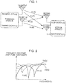
- Fig. 1 is a diagram illustrating an example of a configuration of a MIMO communication system.
- a transmission apparatus includes a plurality of transmitting antennas.
- a reception apparatus includes a plurality of receiving antennas.
- a radio transmission path between one transmitting antenna and one receiving antenna is referred to as a channel.
- a channel H 11 (k) exists between a first transmitting antenna and a first receiving antenna
- a channel H 12 (k) exists between the first transmitting antenna and a second receiving antenna
- a channel H 21 (k) exists between a second transmitting antenna and the first receiving antenna
- a channel H 22 (k) exists between the second transmitting antenna and the second receiving antenna.
- a mixture of, a direct wave, a reflected wave, a diffracted wave, and/or a scattered wave occurs.
- Values of channels H 11 (k), H 12 (k), H 21 (k), and H 22 (k) indicate frequency responses of the respective channels. Each frequency response is represented by a complex number with an index k of frequency.
- the transmission apparatus transmits different transmission data from the respective transmitting antennas simultaneously, that is, at the same sampling timing in a D/A converter.
- the reception apparatus includes a plurality of receiving antennas. The reception apparatus receives reception data at the respective receiving antennas simultaneously, that is, at the same sampling timing in an A/D converter. However, there is a difference in delay among the channels, and thus all pieces of transmission data transmitted simultaneously from the transmission apparatus are not necessarily received at the same time by the reception apparatus.
- Fig. 2 is a diagram illustrating an example of an amplitude component distribution of a frequency response.
- frequency responses are different among channels, and a correlation among channels is low.
- the reception apparatus performs, for example, a process described below. That is, the reception apparatus multiplies the reception data received via the first receiving antenna and the reception data received via the second receiving antenna by respective complex weighting coefficients, and adds results together such that reception signals via the channel H 11 (k) and the channel H 12 (k) are intensified while reception signals via the channel H 21 (k) and the channel H 22 (k) are suppressed.
- the weighting factors are calculated using, for example, an MMSE (Minimum Mean Square Error) method described later.
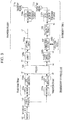
- Fig. 3 is a diagram illustrating an example of a configuration of the transmission apparatus 100.
- the transmission apparatus 100 includes a MAC unit 101, a stream generator 102, encoders 103a and 103b, data modulators 104a and 104b, a precoder 105, GI (Guard Interval) adders 106a and 106b, a symbol order reverser 107, data symbol buffers 108a and 108b, a phase shifter 109, transmission F/E circuits (filter, D/A converter, and RF circuits) 110 an and 110b, and transmitting antennas 111a and 111b.
- GI Guard Interval
- the transmission apparatus 100 performs ⁇ /2-BPSK modulation by the data modulators 104a and 104b and transmits different data from the respective transmitting antennas 111a and 111b.
- the MAC unit 101 generates transmission data and outputs the generated transmission data to the stream generator 102.
- the stream generator 102 divides the transmission data into two pieces, that is, first stream data and second stream data. For example, the stream generator 102 assigns odd-numbered bits of the transmission data to the first stream data while the stream generator 102 assigns even-numbered bits of the transmission data to the second stream data.
- the stream generator 102 outputs the first stream data to the encoder 103a, and outputs the second stream data to the encoder 103b.
- the stream generator 102 may calculate CRC (Cyclic Redundancy Check) for the transmission data and may add the resultant CRC at the end of the transmission data, and thereafter, the stream generator 102 may generate the stream data.
- CRC Cyclic Redundancy Check
- a process performed on the first stream data output from the stream generator 102 is referred to as a first transmission stream process.
- the first transmission stream process is performed by the encoder 103a and the data modulator 104a.
- a process performed on the second stream data output from the stream generator 102 is referred to as a second transmission stream process.
- the second transmission stream process is performed by the encoder 103b and the data modulator 104b.
- the encoders 103a and 103b perform an error correction coding process on each piece of stream data.
- the encoders 103a and 103b may employ, for example, LDPC (Low Density Parity Check) coding as the error correction coding scheme.
- LDPC Low Density Parity Check
- the data modulators 104a and 104b perform a modulation process on each piece of stream data obtained as a result of the error correction coding process performed by the encoders 103a and 103b.
- the data modulators 104a and 104b employ, for example, ⁇ /2-BPSK as the data modulation scheme.
- Fig. 4A illustrates an example of a constellation for ⁇ /2-BPSK for a case where a symbol index m is an odd number.
- Fig. 4B illustrates an example of a constellation of ⁇ /2-BPSK for a case where a symbol index m is an even number.
- Data also referred to as a "modulated signal”
- a modulated symbol s 1 (m)
- data output by the data modulator 104b is referred to as a modulated symbol s 2 (m) where m is a positive integer representing a symbol index.
- the modulated symbols s 1 (m) and s 2 (m) have values described below.
- the precoder 105 multiplies the modulated symbols s 1 (m) and s 2 (m) output by the data modulators 104a and 104b by a 2-by-2 matrix as shown in equation 1 thereby determining precoded symbols x 1 (m) and x 2 (m).
- Equation 1 the 2-by-2 matrix multiplied to s 1 (m) and s 2 (m) is referred to as a precoding matrix (hereinafter denoted by "G"). That is, the precoding matrix G is represented by equation 2.
- the precoding matrix given by equation 2 is merely an example, and another matrix may be employed as the precoding matrix G.
- another unitary matrix may be employed as the precoding matrix G.
- the unitary matrix is a matrix satisfying equation 2-1.
- G H denotes a complex conjugate transpose of the matrix G
- I denotes an identity matrix.
- the precoding matrix G in equation 2 satisfies equation 2-1, and thus the precoding matrix G in equation 2 is an example of a unitary matrix.
- x 1 (m) and x 2 (m) satisfy a relationship expressed in equation 2-2 where a symbol "*" denotes complex conjugate.
- Equation 2-3 Another example of a precoding matrix G is shown in equation 2-3.
- Equation 2-5 Another example of a precoding matrix G is shown in equation 2-5.
- a is a constant of a real number and b is a constant of a complex number.
- ⁇ is a constant indicating an amount of phase shift.
- equation 2-5 in a case where a and b are each equal to 1 and ⁇ is equal to - ⁇ /4, equation 2-5 is equal to equation 2.
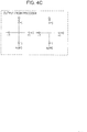
- Fig. 4C is a diagram illustrating an example of a constellation of output data x 1 (m) and x 2 (m) output by the precoder 105.
- the constellation shown in Fig. 4C is the same as the constellation in QPSK modulation. That is, the precoder 105 converts two modulated symbol s 1 (m) and s 2 (m) modulated by the ⁇ /2-BPSK into two precoded symbols x 1 (m) and x 2 (m) corresponding to QPSK symbols according to equation 1.
- a process performed on the precoded symbol x 1 (m) output from the precoder 105 is referred to as a first transmission RF chain process.
- the first transmission RF chain process is performed by the GI adder 106a, the data symbol buffer 108a, the transmission F/E (Front End) circuit 110a, and the transmitting antenna 111a.
- a process performed on the precoded symbol x 2 (m) output from the precoder 105 is referred to as a second transmission RF chain process.
- the second transmission RF chain process is performed by the complex conjugate GI adder 106b, the symbol order reverser 107, the data symbol buffer 108b, the phase shifter 109, the transmission F/E circuit 110b, and the transmitting antenna 111b.
- Fig. 5A is a diagram illustrating an example of a method of adding GI by the GI adder 106a and the complex conjugate GI adder 106b.
- the GI adder 106a divides the precoded symbol x 1 (m) into data blocks each including 448 symbols. For example, first 448 symbols in x 1 (m) are put into a first data block (x 1 (1, n)), next 448 symbols are put into a second data block (x 1 (2, n)), ..., and b-th 448 symbols are put into a b-th data block (x 1 (b, n)).
- n is an integer greater than or equal to 1 and smaller than or equal to 448
- b is a positive integer. That is, x 1 (b, n) denotes an n-th precoded symbol in a b-th data block. Note that the numbers of symbols employed above are merely examples, and the numbers of symbols in the present example may be different from these examples.
- the GI adder 106a adds a 64-symbol GI in front of each data block.
- the GI is a symbol sequence obtained as a result of performing ⁇ /2-BPSK modulation on a known sequence. Furthermore, the GI adder 106a adds a 64-symbol GI after a last data block. As a result, a transmission symbol u1 such as that shown in Fig. 5A is generated.
- the complex conjugate GI adder 106b divides the precoded symbol x 2 (m) into data blocks each including 448 symbols, adds a 64-symbol GI in front of each data block, and adds a 64-symbol GI after a last data block.
- the GIs added by the complex conjugate GI adder 106b are complex conjugates of the GIs added by the GI adder 106a. As a result, a transmission symbol u2 such as that shown in Fig. 5A is generated.
- GI 1 (p) denote a p-th symbol in the GI added by the GI adder 106a
- GI 2 (p) denote a p-th symbol in the GI added by the complex conjugate GI adder 106b.
- p is an integer greater than or equal to 1 and smaller than or equal to 64.
- GI 1 (p) and GI 2 (p) have a relationship described in equation 3, where a symbol "*" denotes complex conjugate.
- Fig. 5B illustrates an example of a DFT signal X 1 (b, k) obtained as a result of performing a DFT (Discrete Fourier Transform) on a symbol block (refer to the transmission symbol u1 in Fig. 5A ) obtained by adding GI(p) to a precoded symbol x 1 (b, n).
- Fig. 5C illustrates an example of a DFT signal X 2 (b, k) obtained as a result of performing a DFT on a symbol block (refer to the transmission symbol u2 in Fig. 5A ) obtained by adding GI*(p) to a precoded symbol x 2 (b, n).
- a frequency characteristic of a signal output by the GI adder 106a is explained below with reference to the DFT signal X 1 (b, k).
- a frequency characteristic of a signal output by the GI adder 106b is also explained below with reference to the DFT signal X 2 (b, k).
- x 2 (b, n) and GI*(p) are respectively complex conjugates of x 1 (b, n) and GI(p), and thus the DFT signal X 2 (b, k) is a signal obtained by performing frequency inversion on the complex conjugate of the DFT signal X 1 (b, k) and further performing phase shifting in frequency domain. That is, X 2 (b, k) is represented by equation 3-1.
- Equation 3-1 The amount of phase shift (exp(j ⁇ 2 ⁇ k/N)) in equation 3-1 is denoted by W as shown below.
- Fig. 6A illustrates a symbol order reversion process according to the claimed invention, performed by the symbol order reverser 107.
- the symbol order reverser 107 reverses the order of the precoded symbol x 2 (b, n) in each symbol block, and also reverse the order of GI(p) added to the precoded symbol x 2 (b, n).
- the precoded symbol x 2 (time reversal) (b, n) obtained as a result of reversing the order is represented by equation 4. That is, the symbol sequence reversed in order is denoted by "-n".
- GI 2 ( time reversal )(p) reversed in order is represented by equation 5. That is, the symbol sequence reversed in order is denoted by "-p".
- Fig. 6C illustrates an example of a DFT signal X 1 (b, k) obtained as a result of performing DFT on a symbol block (refer to the transmission symbol u1 in Fig. 5A ) obtained by adding GI(p) to the precoded symbol x 1 (b, n).
- Fig. 6C is similar to Fig. 5B .
- Fig. 6D illustrates an example of a reversed DFT signal X 2r (b, k) obtained as a result of performing DFT on a reversed symbol x 2 (-m).
- the reversed symbol x 2 (-m) includes a precoded symbol signal x 2 (b, -n) obtained as a result of performing symbol order reversion and GI*(-p) obtained as a result of performing symbol order reversion on the complex conjugate of GI.
- a frequency characteristic of a signal output by the symbol order reverser 107 is explained below with reference to the reversed DFT signal X 2r (b, k).
- x 2 (b, -n) and GI*(-p) are respectively complex conjugates of symbol blocks obtained as a result of performing the order reversion on x 1 (b, n) and GI(p), and thus X 2r (b, k) is represented by equation 5-2.
- the reversed DFT signal X 2r (b, k) is a signal obtained as a result of applying a phase shift to the complex conjugate of the DFT signal X 1 (b, k).
- N included in W is a DFT size (for example, a length "512" of a symbol block).
- Fig. 6B illustrates an alternative symbol order reversion process according to the claimed invention, performed by the symbol order reverser 107.
- the symbol order reverser 107 reverses the order of a symbol sequence (a sequence of symbols) in each whole symbol block.
- the symbol order reverser 107 may remove GI added at the location after the last data block and may add a symbol-order-reversed GI in front of the first data block.
- the symbol block is, for example, as described above, a 512-symbol block obtained by combining a 64-symbol GI and a 448-symbol data block.
- the symbol order reverser 107 may sequentially store data symbols in the transmission symbol u2 output by the complex conjugate GI adder 106b in the data symbol buffer 108b such that 448 symbols are stored at a time, and may read data symbols in an order different from (in an order opposite to) the order in which data symbols are stored in the data symbol buffer 108b thereby reversing the order of symbols. That is, the data symbol buffer 108b may be of a type of a LIFO (Last In, First Out) buffer.
- the data symbol buffer 108b may be a memory, a RAM, a register, or the like.
- the process performed by the symbol order reverser 107 to reverse the symbol order of the transmission symbol u2 causes output data to have a delay with respect to input data.
- a delay with a length equal to the delay that occurs in the symbol order reverser 107 is applied to a data symbol (for example, x 2 (b, n)) in the transmission symbol u2 output by the GI adder 106a.
- a data symbol for example, x 2 (b, n)
- the transmission symbol u1 output by the GI adder 106a and the transmission symbol u2 output by the complex conjugate GI adder 106b are transmitted at the same timing.
- a symbol block obtained by reversing the transmission symbol u2 by the symbol order reverser 107 is also referred to as a reversed symbol u2r.
- the phase shifter 109 applies a different phase shift to each data symbol (for example, x 2 (b, n)) in the reversed symbol u2r output by the symbol order reverser 107. That is, the phase shifter 109 changes phases of symbols by different amounts depending on the symbols.
- the phase shifter 109 applies a phase shift to a data symbol (for example, x 2 (b, n)) according to equation 6, and applies a phase shift to GI (for example, GI 2 (p)) according to equation 7. Note that in equation 6 and equation 7, ⁇ denotes the amount of phase shift.
- the transmission apparatus 100 does not give a phase shift to x1(b, n) in transmission symbols output by the precoder 105 but gives a phase shift to x2(b, n) in the transmission symbols output by the precoder 105.
- the transmission symbol obtained as a result of the phase shift is represented by equation 8.
- phase shifter 109 is provided in the second transmission RF chain process
- a phase shifter may be provided in both the first transmission RF chain process and the second transmission RF chain process.
- a phase shift matrix shown in equation 9 may be used.
- equation 8 in a case where n in equation 8 is greater than or equal to 1 and smaller than or equal to 448, this equation may be regarded as an equation in terms of a data symbol (for example equation 6), while in case where n is greater than or equal to 449 and smaller than or equal to 512, the equation may be regarded as an equation in terms of GI (for example, equation 7 for a case where p is given by a value obtained as a result of subtracting 448 from n in equation 8).
- n is greater than or equal to 1 and smaller than or equal to 512
- x 1 (b, n) and x 2 (b, -n) include both a data symbol and GI.
- Fig. 6E is a diagram illustrating a DFT signal T 1 (b, k) obtained by performing DFT on the phase-shifted symbol t 1 (b, n) on a symbol block-by-symbol block basis.
- Fig. 6F is a diagram illustrating a DFT signal T 2 (b, k) obtained by performing DFT on the phase-shifted symbol t 2 (b, n) on a symbol block-by-symbol block basis.
- Equation 8 indicates that X 1 (b, k) and T 1 (b, k) are equal to each other. That is, Fig. 6C and Fig. 6E are the same except that a symbol X 1 is replaced by a symbol T 1 .
- T 2 (b, k) shown in Fig. 6F is a signal obtained by applying a phase shift in time domain to X 2r (b, k).
- the frequency index is shifted in frequency domain by an amount corresponding to a frequency bin d calculated according to equation 9-1.
- N is a DFT size (for example, a length "512" of a symbol block).
- X 1 (b, k) is transmitted as T 1 (b, k) and T 2 (b, k + d) according to equation 9-2 using two transmitting antennas and two frequency indices k and k + d.
- a space diversity effect and a frequency diversity effect are obtained.
- the transmission apparatus 100 is capable of enhancing the frequency diversity effect and the data throughput by setting the amount of phase shift ⁇ to a value close to ⁇ radian (180°) or - ⁇ radian (-180°).
- the transmission apparatus 100 may set the amount of phase shift ⁇ to a value different from ⁇ radian (180°). This makes it possible to easily achieve a signal separation between the transmission signal associated with the transmitting antenna 111a and the transmission signal associated with the transmitting antenna 111b. Furthermore, it is also possible to increase the data throughput.
- a method of giving a phase shift other than ⁇ radian to a transmission symbol in OFDM is disclosed, as a PH (Phase Hopping) technique, in NPL 2.
- PH Phase Hopping
- NPL 2 Single carrier transmission is used, and symbol order reversion is performed in the second transmission stream process. This makes it possible to easily separate two transmission signals from each other. Furthermore, a relatively high frequency diversity effect is achieved.
- the transmission apparatus 100 may set the amount of phase shift ⁇ to a value such as -7 ⁇ /8 radian (d is -224), -15 ⁇ /16 radian (d is 240), or the like.
- the transmission F/E circuits 110a and 110b include digital and analog filters, a D/A converter, and an RF (radio) circuit.
- the transmission F/E circuit 110a converts transmission data v1 (a signal including GI(p) and t1(b, n) shown in Fig. 8 ) output from the data symbol buffer 108a to a radio signal, and outputs the resultant radio signal to the transmitting antenna 111a.
- the transmission F/E circuit 110b converts transmission data v2 (a signal including GI*(-p) and t2(b, -n) shown in Fig. 8 ) output from the phase shifter 109 to a radio signal, and outputs the resultant radio signal to the transmitting antenna 111b.
- the transmitting antenna 111a transmits the radio signal output from the transmission F/E circuit 110a.
- the transmitting antenna 111b transmits the radio signal output from the transmission F/E circuit 110b. That is, the transmitting antennas 111a and 111b respectively transmit different radio signals.
- the transmission apparatus 100 performs the precoding on two pieces of transmission stream data and then performs the symbol order reversion and the phase shift on one of the two pieces of transmission stream data. This makes it possible to enhance the space diversity effect and the frequency diversity effect. Furthermore, it is also possible to reduce the error rate in data communication and enhance the data throughput.
- Fig. 7 is a diagram illustrating a configuration of a reception apparatus 200.
- Receiving antennas 201a and 201b respectively receive radio signals.
- a process performed on a reception signal received by the receiving antenna 201a is referred to as a first reception RF chain process.
- the first reception RF chain process is performed by a reception F/E circuit 202a, a time domain synchronization unit 203a, and a DFT unit 205a.
- a process performed on a reception signal received by the receiving antenna 201b is referred to as a second reception RF chain process.
- the second reception RF chain process is performed by a reception F/E circuit 202b, the time domain synchronization unit 203b, and a DFT unit 205b.
- the reception F/E circuits 202a and 202b include, for example, an RF circuit, an A/D converter, a digital filter, an analog filter, and a down sampling unit, and the reception F/E circuits 202a and 202b convert radio signals into digital baseband signals.
- the time domain synchronization units 203a and 203b perform control to achieve timing synchronization of reception packets. Note that the time domain synchronization unit 203a and the time domain synchronization unit 203b may exchange timing information with each other and may achieve timing synchronization between the first reception RF chain process and the second reception RF chain process.
- a channel estimator 204 calculates a frequency response of a radio channel between the transmission apparatus and the reception apparatus using the reception signal associated with the first reception RF chain process and the reception signal associated with the second reception RF chain process. That is, H 11 (k), H 12 (k), H 21 (k), and H 22 (k) in Fig. 1 are calculated for each frequency index k.
- the DFT units 205a and 205b divide the reception data into DFT blocks and perform DFT.
- Each DFT block includes, for example, 512 symbols.
- Fig. 8 is a diagram illustrating a method of dividing reception data into DFT blocks by the DFT units 205a and 205b.
- y 1 (n) denote reception data subjected to the first reception RF chain process (input data applied to the DFT unit 205a), and let y 2 (n) denote reception data subjected to the second reception RF chain process (input data applied to the DFT unit 205b).
- y 1 (n) denote reception data subjected to the first reception RF chain process
- y 2 (n) reception data subjected to the second reception RF chain process
- the transmission apparatus 100 transmits two radio signals (transmission data v1 and transmission data v2 shown in Fig. 8 ) using the two transmitting antennas 111a and 111b.
- the two radio signals each create, in a channel, a direct wave and a plurality of delay waves, which arrive at the receiving antennas 201a and 201b.
- reception signals each may include, for example, a diffracted wave and a scattered wave in addition to the direct wave and the delay waves.
- the DFT unit 205a determines a first DFT block time such that a direct wave and a delay wave of a data block t 1 (1, n) of transmission data v1 and data block t 2 (1, n) of a transmission data v2 are included.
- a result of DFT calculation of the first DFT block is denoted as Y 1 (1, k), where k indicates, as described above, a frequency index and is an integer, for example, greater than or equal to 1 and smaller than or equal to 512.
- results of DFT calculations of a b-th DFT block calculated by the DFT units 205a and 205b are respectively denoted as Y 1 (b, k) and Y 2 (b, k) (b is an integer greater than 1).
- the reception apparatus 200 calculates estimated values of the transmitted modulated symbols si(n) and s 2 (n) using an MMSE weight calculation unit 206, an MMSE filter 207, an inverse phase shifter 208, an IDFT (inverse DFT) unit 209a, an IDFT and symbol order reverser 209b, and an inverse precoder 210.
- an MMSE weight calculation unit 206 calculates estimated values of the transmitted modulated symbols si(n) and s 2 (n) using an MMSE weight calculation unit 206, an MMSE filter 207, an inverse phase shifter 208, an IDFT (inverse DFT) unit 209a, an IDFT and symbol order reverser 209b, and an inverse precoder 210.
- the output signals Y 1 (b, k) and Y 2 (b, k) output from the DFT units 205a and 205b in the reception apparatus 200 are represented using channel values as equation 10.
- T 1 (b, k) is a signal obtained as a result of performing DFT on a symbol block (t 1 (b, n) in equation 8) in the transmission apparatus 100.
- T 2 (b, k) is a signal obtained as a result of performing DFT on a symbol block (t 2 (b, n) in equation 8) in the transmission apparatus 100.
- Z 1 (b, k) is a signal obtained as a result of performing DFT on noise in the first RF chain unit.
- Z 2 (b, k) is a signal obtained as a result of performing DFT on noise in the second RF chain unit.
- Equation 10 can be expressed using matrices as in equation 11.
- Equation 11 a channel matrix H 2 ⁇ 2 (k) is determined as shown in equation 12.
- the MMSE weight calculation unit 206 calculates a weight matrix W 2 ⁇ 2 (k) according to equation 12-1.
- H H denotes a complex conjugate transpose of a matrix H
- ⁇ 2 is the variance of noise Z 1 (b, k) and noise Z 2 (b, k)
- I 2 ⁇ 2 is a 2-by-2 identity matrix.
- the MMSE filter 207 calculates estimated values T ⁇ 1 (b, k) and T ⁇ 2 (b, k) of T 1 (b, k) and T 2 (b, k) according to equation 12-2. Note that a process associated with the estimated value T ⁇ 1 (b, k) is referred to as a first reception stream process, and a process associated with the estimated value T ⁇ 2 (b, k) is referred to as a second reception stream process.
- the calculation according to equation 12-2 is referred to as an MMSE algorithm.
- the MMSE filter 207 acquires estimated values of phase-shifted data symbols t 1 (b, n) and t 2 (b, n) based on the MMSE algorithm from reception data y1 and y2 (see Fig. 8 ) including a mixture of t 1 (b, n) included in the transmission data v1, t 2 (b, n) included in the transmission data v2, and direct waves and delay waves thereof.
- the MMSE filter 207 performs the calculation on the frequency-domain signal as shown in equation 12-2 using estimated channel values (estimated values of channel frequency response) H 11 (k), H 12 (k), H 21 (k), and H 22 (k).
- the inverse phase shifter 208 performs a process inverse to the process performed by the phase shifter 109 shown in Fig. 3 .
- the frequency indices k and -k are shifted by amounts corresponding to a frequency bin d as shown in Fig. 6F where d is calculated according to equation 9-1. Therefore, the inverse phase shifter 208 shifts a frequency-domain signal of the second reception stream output from the MMSE filter 207 by an amount corresponding to -d. That is, the inverse phase shifter 208 performs a process in frequency domain according to equation 12-3.
- the IDFT unit 209a and the IDFT and symbol order reverser 209b may be exchanged with the inverse phase shifter 208, and an inverse phase shift may be applied after IDFT is performed on the output from the MMSE filter.
- the inverse phase shifter 208 performs a process in time domain according to equation 12-4.
- the inverse phase shifter 208 when the inverse phase shifter 208 gives an inverse phase shift to the second reception stream data, the inverse phase shifter 208 performs a process that is the same as the multiplication given by the matrix P defined by equation 9 because the symbol order is reversed by the IDFT and symbol order reverser 209b.
- the IDFT unit 209a performs IDFT on the first reception stream data output from the inverse phase shifter 208.
- the IDFT and symbol order reverser 209b performs IDFT on the second reception stream data output from the inverse phase shifter 208 and reverses a symbol order of each DFT block.
- the inverse precoder 210 multiplies an inverse matrix of the precoding matrix G used by the precoder 105 shown in Fig. 3 to the first reception stream data and the second reception stream data thereby calculating estimated values of s1(b, n) and s2(b, n). Equation 12-5 indicates the process performed by the inverse precoder 210.
- Data demodulators 211a and 211b demodulate data of the estimated values of s1(b, n) and s2(b, n) output from the inverse precoder 210 thereby determining the estimated values in the form of bit data.
- Decoders 212a and 212b perform LDPC error correction process on the estimated values in the form of bit data.
- a stream aggregator 213 aggregates the first reception stream data and the second reception stream data and transmits a result as reception data to a MAC unit 215.
- a header data extractor 214 extracts header data from the reception data, and determines, for example, MCS (Modulation and Coding Scheme) and the amount of phase shift ⁇ used by the phase shifter 109 shown in Fig. 3 .
- the header data extractor 214 may make control as to the precoding matrix G applied to the inverse precoder 210, as to whether the symbol reversion process is to be performed in the IDFT and the symbol order reverser 209b, and as to the amount of phase shift ⁇ used by the inverse phase shifter 208.
- the MMSE filter 207 performs the estimation using the transmission signals T 1 (b, k) and T 2 (b, k) obtained as a result of performing frequency shift on the second transmission stream data, and thus it is possible to achieve further higher frequency diversity effect. Furthermore, it is possible to achieve a reduction in reception error rate and an increase in data throughput.
- the transmission apparatus 100 processes the second precoded symbol such that the complex conjugate of GI added to the first precoded symbol is added, the symbol order is reversed, and the phase shift (phase changing) is given.
- the transmission apparatus 100 performs MIMO transmission by performing ⁇ /2-BPSK modulation using the data modulators 104a and 104b.
- a transmission apparatus 300 (see Fig. 9 ) performs MIMO transmission using data modulators 104a and 104b such that a plurality of data modulation schemes (for example, ⁇ /2-BPSK modulation and ⁇ /2-QPSK modulation) are switched.
- Fig. 9 is a diagram illustrating an example of a configuration of a transmission apparatus 300 according to the second example. Note that same constituent elements as those in Fig. 3 are denoted by same numbers, and a further description thereof is omitted.
- Data modulators 104c and 104d perform data modulation on encoded data output by encoders 103a and 103b under the control of a MAC unit 101.
- Fig. 10A is a diagram illustrating an example of a constellation for ⁇ /2-QPSK modulation.
- Modulated symbols s 1 (m) and s 2 (m) output from the data modulators 104c and 104d each take one of values +1, -1, +j, and -j.
- a constellation for ⁇ /2-BPSK modulation is as shown in Fig. 4A .
- the precoder 105a changes a precoding matrix depending on a data modulation scheme used by the data modulator 104c or 104d thereby performing a precoding process shown in equation 13.
- the precoder 105a uses, for example, a precoding matrix G shown in equation 2, equation 2-3, or equation 2-5.
- the precoder 105a uses, for example, a precoding matrix G shown in equation 14.
- constellation is similar to that of ⁇ /2-QPSK (see Fig. 4C ).
- constellation is similar to that of 16QAM (see Fig. 10B ).
- the number of symbol candidate points in ⁇ /2-BPSK is 2
- the number of symbol candidate points in ⁇ /2-QPSK is 4
- the number of symbol candidate points in ⁇ /2-16QAM is 16. That is, precoding results in an increase in the number of symbol candidate points in constellation.
- a second transmission RF chain process is performed differently depending on the modulation scheme and the type of the precoding matrix G.
- the transmission apparatus 300 performs the second transmission RF chain process using a complex conjugate GI adder 106b and a symbol order reverser 107 as with the transmission apparatus 100 shown in Fig. 3 .
- the complex conjugate GI adder 106b adds a complex conjugate of GI to an output x 2 (m) output from the precoder 105a.
- the symbol order reverser 107 performs a symbol order reversion process on the output x 2 (n) added with the complex conjugate of GI.
- the transmission apparatus 300 In a case where ⁇ /2-QPSK is used in the data modulators 104c and 104d and a precoding matrix G shown in equation 14 is used in the precoder 105a, the transmission apparatus 300, unlike the transmission apparatus 100 shown in Fig. 13 , performs the second transmission RF chain process using a GI adder 106c.
- the GI adder 106c adds, to the output x 2 (m) output from the precoder 105a, the same GI as the GI added by the GI adder 106a in the first RF chain process.
- the GI adder 106c may add GI (GI2) which is different from GI(GI1) added by the GI adder 106a. Sequences which are orthogonal to each other (cross-correlation is 0) may be respectively used as GI1 and GI2. For example, a Ga64 sequence defined in the 11ad standard (see NPL 1) may be used as G11, and a Gb64 sequence defined in the 11ad standard may be used as G12.
- a combination of ⁇ /2-BPSK modulation and a precoding matrix G according to equation 2, equation 2-3, or equation 2-5 is referred to as a first precoding scheme type.
- a combination of ⁇ /2-QPSK modulation and a precoding matrix G according to equation 14 is referred to as a second precoding scheme type. A method of distinguishing between the first precoding scheme type and the second precoding scheme type will be described later.
- a selector 112a selects an output of a data symbol buffer 108a, and a selector 112b selects an output of a symbol order reverser 107.
- the selector 112a selects an output of the GI adder 106a, and the selector 112b selects an output of the GI adder 106c.
- selector 112a may be disposed at a location after the GI adder 106a, and the selector 112b may be disposed at a stage located after the precoder 105a.
- the signal subjected to the second transmission RF chain process is a signal obtained as a result of inverting frequencies of the signal subjected to the first transmission RF chain process and is in a complex conjugate relationship with the signal subjected to the first transmission RF chain process.
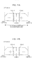
- x 1 (b, n) and x 2 (b, n) are not in a complex conjugate relationship. Therefore, in frequency domain, as shown in Fig. 11A and Fig. 11 B , the signal subjected to the first transmission RF chain process and the signal subjected to the second transmission RF chain process are transmitted at the same frequency. For example, X 1 (b, k) and X 2 (b, k) are transmitted at an identical frequency, and X 1 (b, -k) and X 2 (b, -k) are transmitted at an identical frequency.
- the precoding scheme is the first precoding scheme type.
- the transmission apparatus 300 adds a complex conjugate GI in the second transmission RF chain process and performs a symbol order reversion. That is, the selector 112b selects the output from the symbol order reverser 107.
- the selector 112b selects the output from the GI encoder 106c.
- the transmission apparatus 300 can achieve a frequency diversity effect depending on the phase shift ⁇ given by the phase shifter 109 (and d calculated from ⁇ according to equation 9-1) regardless of the data modulation scheme and the type of the precoding matrix, as shown in Fig. 6E and Fig. 6F .
- the precoding scheme is the first precoding scheme type.
- the precoding scheme is the second precoding scheme type.
- the selectors 112a and 112b may select input data depending on the type of the precoding scheme.
- the transmission apparatus 300 may employ the same transmission parameters in transmission as those in ⁇ /2-QPSK and ⁇ /2-16QAM used when transmission is performed without performing precoding.
- the transmission parameters include, for example, setting values of back-off of RF amplifiers in the transmission F/E circuits 110a and 110b. That is, the transmission apparatus 300 may perform precoding using one of equations (2) or (14) depending on the modulation scheme. This makes it possible to perform transmission without changing the configurations of the transmission F/E circuits 110a and 110b. A reason for this is described below.
- a setting value of back-off for an RF amplifier in a transmission F/E circuit is set or changed properly depending on transmission constellation mapping ( Fig. 10A, Fig. 10B , etc.).
- transmission constellation mapping Fig. 10A, Fig. 10B , etc.
- PAPR peak power
- Performing of the precoding process can cause a change in constellation mapping of the transmission signal, and thus setting of the transmission F/E circuit is changed.
- the transmission apparatus 300 by performing the precoding process using equation 2 or equation 14, it is possible to obtain constellation mapping which is the same as the constellation mapping in known modulation although the constellation mapping becomes different from that which were before the precoding process was performed. That is, the transmission signal has known constellation mapping regardless of whether the precoding process is performed or not, and thus it becomes unnecessary to change the configuration and setting of the transmission F/E circuit, and controlling becomes easy.
- the transmission apparatus 300 adds, to the second precoded symbol, a complex conjugate of GI added to the first precoded symbol, performs symbol order reversion, and gives a phase shift (phase changing).
- the transmission apparatus 300 performs MIMO transmission such that the symbol order reverser 107 performs the symbol order reversion on the data symbols and symbols of GI.
- the transmission apparatus 400 (see Fig. 12 ) performs MIMO transmission such that the GI adders 106d and 106e add sequences (for example, orthogonal sequences) which are different for each stream.
- Fig. 12 is a diagram illustrating an example of a configuration of a transmission apparatus 400 according to a modification of the second example. Note that same constituent elements as those in Fig. 9 are denoted by same numbers, and a further description thereof is omitted.
- GI adders 106d and 106e are disposed at stages located after the selectors 112a and 112b and the phase shifter 109. Unlike the transmission apparatus 300 shown in Fig. 9 , the transmission apparatus 400 may add a predefined GI symbol on a stream-by-stream basis regardless of the modulation scheme.
- Fig. 13 and Fig. 14 are diagrams each illustrating an example of a transmission symbol format of each of outputs (v3, v4) from the GI adders 106d and 106e in the transmission apparatus 400.
- the examples shown in Fig. 13 are formats for a case where data symbols are modulated by ⁇ /2-BPSK, while the examples shown in Fig. 14 are formats for a case where data symbols are modulated by a modulation scheme other than ⁇ /2-BPSK.
- the GI adder 106d divides the precoded symbol x 1 (m) into data blocks each including 448 symbols, and adds a 64-symbol GI (GI 1 (p)) in front of each data block.
- the GI is a symbol sequence obtained as a result of performing ⁇ /2-BPSK modulation on a known sequence. Furthermore, the GI adder 106d adds a 64-symbol GI after a last data block. As a result, a transmission symbol v3 such as that shown in Fig. 13 and Fig. 14 is generated. Note that the numbers of symbols employed above are merely examples, and the numbers of symbols in the present example may be different from these examples.
- the GI adder 106e divides the precoded symbol x 2 (m) into data blocks each including 448 symbols, adds a 64-symbol GI (GI 2 (p)) in front of each data block, and adds a 64-symbol GI after a last data block.
- a transmission symbol v4 such as that shown in Fig. 13 and Fig. 14 is generated.
- GI added by the GI adder 106e may be different from a sequence of GI added by the GI adder 106d.
- the reception apparatus 200 may perform MMSE equalization according to equation 12-2 as in the first example in the reception process.
- the reception apparatus 200 may detect an error of the channel estimation matrix by comparing the MMSE-equalized GI symbol (part associated with GI in the output from the MMSE filter 207) with a known GI symbol, and may correct the channel estimation matrix.
- a calculation is performed to determine a correlation between the GI 1 (p) estimated by MMSE equalization and the known GI 1 (p).
- a residual error of MMSE equalization is reduced and, for example, a value of phase shift is calculated with high accuracy.
- the reception apparatus 200 generates replica signals of GI 1 (p) and GI 2 (p) according to equation 16.
- the replica signals are estimated values of signals received via a receiving antenna in a case where a known pattern (for example, GI 1 (p) and GI 2 (p)) is transmitted, and the replica signals are calculated by multiplying the known pattern by the channel matrix (see equation 12).
- X G1 (k) and X G2 (k) are signals (frequency domain signals of GI) obtained as a result of performing DFT on time-domain GI signals (symbols) GI 1 (p) and GI 2 (p).
- Y G1 (k) and Y G2 (k) are frequency-domain signals obtained when the reception apparatus 200 receives GI 1 (p) and GI 2 (p). Symbols " ⁇ " added to Y G1 (k) and Y G2 (k) indicate that these are estimated values.
- the reception apparatus 200 subtracts Y ⁇ G1 (k) from a reception signal Y 1 (b, k) thereby estimating a data signal component Y ⁇ D1 (k) included in the reception signal, and subtracts Y ⁇ G2 (k) from a reception signal Y 2 (b, k) thereby estimating a data signal component Y ⁇ D2 (k).
- the reception apparatus 200 performs MMSE equalization on the estimated data signal component Y ⁇ D1 (k) and Y ⁇ D2 (k) given as input signals thereby calculating estimated values T ⁇ D1 (k) and T ⁇ D2 (k) of transmission data symbols.
- Equation 18 The calculation process performed in equation 18 is similar to that in equation 12-2, except that in contrast to equation 12-2 in which inputs Y 1 (b, k) and Y 2 (b, k) include signal components of data and GI, inputs Y ⁇ D1 (k) and Y ⁇ D2 (k) in equation 18 include signal components of data and signal components of GI are removed.
- GI of each stream does not have a complex conjugate relationship and a time order converted relationship, and thus it is difficult for the MMSE filter 207 to achieve a frequency diversity effect in demodulation of the GI symbols similar to the frequency diversity effect achieved in the first example.
- intersymbol interference from GI symbols to data symbols remains after the MMSE equalization, which may result in degradation in reception performance.
- the MMSE filter 207 subtracts the GI symbol replica from the reception signal using equation 16, equation 17, and equation 18 in the MMSE equalization. That is, the MMSE equalization of data symbols is performed after the effect of GI is reduced.
- the reception apparatus 200 performs a reception process including inverse phase shift and inverse precoding on estimated values of transmission data symbols T ⁇ D1 (k) and T ⁇ D2 (k) generated by the MMSE filter 207 using equation 18, in a similar manner to the first example and the second example.
- the transmission apparatus 400 performs the symbol order reversion and the phase shift (phase changing) on the second precoded symbol. Furthermore, different GIs are inserted in the first precoded symbol and the second precoded symbol.
- Each functional block according to the examples described above may be typically realized by an integrated circuit such as an LSI having input and output terminals.
- Each of the functional blocks may be formed individually on one chip, or part or all of the functional blocks may be formed on one chip.
- the system LSI may also be referred to as an IC, an LSI circuit, a super LSI circuit, or an ultra LSI circuit depending on the degree of integration.
- the technique of implementing the integrated circuit is not limited to the LSI, but the integrated circuit may be realized in the form of a dedicated circuit or a general-purpose processor.
- the integrated circuit may also be realized using an FPGA (Field Programmable Gate Array) that can be programmed after the manufacture of the LSI or a reconfigurable processor that is allowed to be reconfigured in terms of the connection or the setting of circuit cells in the inside of the LSI.
- FPGA Field Programmable Gate Array
- the functional blocks may be realized using such a new technique.
- a possible example of a new technique is biotechnology.
- the present disclosure is applicable to a wide variety of communication systems in which a modulated signal is transmitted from a plurality of antennas.
- Reference Signs List
Landscapes
- Engineering & Computer Science (AREA)
- Computer Networks & Wireless Communication (AREA)
- Signal Processing (AREA)
- Physics & Mathematics (AREA)
- Mathematical Physics (AREA)
- Discrete Mathematics (AREA)
- General Physics & Mathematics (AREA)
- Radio Transmission System (AREA)
Claims (5)
- Sendevorrichtung (100), umfassend:eine Signalverarbeitungsschaltung, die dazu eingerichtet ist,ein erstes vorcodiertes Signal (x1) und ein zweites vorcodiertes Signal (x2) durch Ausführen eines Vorcodierungsvorgangs an einem ersten Basisbandsignal (s1) und einem zweiten Basisbandsignal (s2) zu erzeugen;ein erstes bekanntes Signal zu dem ersten vorcodierten Signal hinzuzufügen, wodurch ein erstes Sendesignal erzeugt wird, undein zweites bekanntes Signal, das eine komplex konjugierte Beziehung zu dem ersten bekannten Signal aufweist, zu dem zweiten vorcodierten Signal hinzuzufügen, wobeiein umgekehrtes zweites vorcodiertes Signal erzeugt wird, indem die Reihenfolge einer Symbolsequenz, die das zweite vorcodierte Signal ausbildet, umgekehrt wird, unddie Signalverarbeitungsschaltung einen Reihenfolgenumkehrvorgang an einer Symbolsequenz ausführt, die das zweite bekannte Signal ausbildet, und das umgekehrte zweite vorcodierte Signal mit dem umgekehrten zweiten bekannten Signal verkettet, wodurch ein zweites umgekehrtes Signal (u2r) erzeugt wird; undErzeugen eines zweiten phasengeänderten Signals (v2) durch Ausführen eines Phasenänderungsvorgangs an dem zweiten umgekehrten Signal, wodurch ein zweites Sendesignal aus dem zweiten Basisbandsignal erzeugt wird; undeine Sendeschaltung (111a, 111b), die dazu eingerichtet ist, das erste Sendesignal und das zweite Sendesignal jeweils von verschiedenen Antennen zu senden.
- Sendevorrichtung (100), umfassend:eine Signalverarbeitungsschaltung, die dazu eingerichtet ist,ein erstes vorcodiertes Signal (x1) und ein zweites vorcodiertes Signal (x2) durch Ausführen eines Vorcodierungsvorgangs an einem ersten Basisbandsignal (s1) und einem zweiten Basisbandsignal (s2) zu erzeugen;ein erstes bekanntes Signal zu dem ersten vorcodierten Signal hinzuzufügen, wodurch ein erstes Sendesignal erzeugt wird, undein zweites bekanntes Signal, das eine komplex konjugierte Beziehung zu dem ersten bekannten Signal aufweist, zu dem zweiten vorcodierten Signal hinzuzufügen,wobei die Signalverarbeitungsschaltung einen Reihenfolgenumkehrvorgang an einer Symbolsequenz ausführt, die man als Ergebnis der Verkettung des zweiten bekannten Signals mit dem zweiten vorcodierten Signal erhält, wodurch ein zweites umgekehrtes Signal (u2r) erzeugt wird; undein zweites phasengeändertes Signal (v2) durch Ausführen eines Phasenänderungsvorgangs an dem zweiten umgekehrten Signal zu erzeugen, wodurch ein zweites Sendesignal aus dem zweiten Basisbandsignal erzeugt wird;und eine Sendeschaltung (111a, 111b), die dazu eingerichtet ist, das erste Sendesignal und das zweite Sendesignal jeweils von verschiedenen Antennen zu senden.
- Sendevorrichtung nach einem der Ansprüche 1 bis 2, bei der die Signalverarbeitungsschaltung weiterhin dazu eingerichtet ist,ein drittes bekanntes Signal zu dem zweiten vorkodierten Signal hinzuzufügen, und auf der Grundlage, ob das erste Basisbandsignal und das zweite Basisbandsignal in einer komplex konjugierten Beziehung stehen, auszuwählen, ob das zweite umgekehrte Signal oder das zweite vorcodierte Signal, das dem dritten bekannten Signal hinzugefügt wird, in den Phasenänderungsvorgang eingegeben werden soll,wodurch das erste Sendesignal und das zweite Sendesignal aus dem ersten Basisbandsignal und dem zweiten Basisbandsignal erzeugt werden.
- Sendeverfahren, das von einer Signalverarbeitungsschaltung ausgeführt wird, umfassend:Erzeugen eines ersten vorcodierten Signals und eines zweiten vorcodierten Signals durch Ausführen eines Vorcodierungsvorgangs an einem ersten Basisbandsignal und einem zweiten Basisbandsignal;Hinzufügen eines ersten bekannten Signals zu dem ersten vorcodierten Signal, wodurch ein erstes Sendesignal erzeugt wird,Hinzufügen eines zweiten bekannten Signals, das eine komplex konjugierte Beziehung zu dem ersten bekannten Signal aufweist, zu dem zweiten vorcodierten Signal,wobei ein umgekehrtes zweites vorcodiertes Signal erzeugt wird, indem eine Symbolfolge, die das zweite vorcodierte Signal ausbildet, einem Reihenfolgenumkehrvorgang unterzogen wird;und bei dem ein Reihenfolgenumkehrvorgang an einer Symbolsequenz ausgeführt wird, die das zweite bekannte Signal ausbildet, und das umgekehrte zweite vorcodierte Signal mit dem umgekehrten zweiten bekannten Signal verkettet und dadurch ein zweites umgekehrtes Signal erzeugt wird,Erzeugen eines zweiten phasengeänderten Signals durch Ausführen eines Phasenänderungsvorgangs an dem zweiten umgekehrten Signal, wodurch ein zweites Sendesignal aus dem zweiten Basisbandsignal erzeugt wird; undSenden des ersten Sendesignals und des zweiten Sendesignals jeweils von verschiedenen Antennen.
- Sendeverfahren, das von einer Signalverarbeitungsschaltung ausgeführt wird, umfassend:Erzeugen eines ersten vorcodierten Signals und eines zweiten vorcodierten Signals durch Ausführen eines Vorcodierungsvorgangs an einem ersten Basisbandsignal und einem zweiten Basisbandsignal;Hinzufügen eines ersten bekannten Signals zu dem ersten vorcodierten Signal, wodurch ein erstes Sendesignal erzeugt wird;Hinzufügen eines zweiten bekannten Signals, das eine komplex konjugierte Beziehung zu dem ersten bekannten Signal aufweist, zu dem zweiten vorcodierten Signal;wobei ein Reihenfolgenumkehrvorgang an einer Symbolsequenz ausgeführt wird, die man als Ergebnis der Verkettung des zweiten bekannten Signals mit dem zweiten vorcodierten Signal erhält, wodurch ein zweites, umgekehrtes Signal erzeugt wird;Erzeugen eines zweiten phasengeänderten Signals durch Ausführen eines Phasenänderungsvorgangs an dem zweiten umgekehrten Signal, wodurch ein zweites Sendesignal aus dem zweiten Basisbandsignal erzeugt wird; undSenden des ersten Sendesignals und des zweiten Sendesignals jeweils von verschiedenen Antennen aus.
Applications Claiming Priority (3)
| Application Number | Priority Date | Filing Date | Title |
|---|---|---|---|
| US201662417536P | 2016-11-04 | 2016-11-04 | |
| JP2017199541A JP7015136B2 (ja) | 2016-11-04 | 2017-10-13 | 送信装置、送信方法、及び、受信装置 |
| PCT/JP2017/038434 WO2018084035A1 (ja) | 2016-11-04 | 2017-10-25 | 送信装置、送信方法、受信装置、および、受信方法 |
Publications (3)
| Publication Number | Publication Date |
|---|---|
| EP3537623A1 EP3537623A1 (de) | 2019-09-11 |
| EP3537623A4 EP3537623A4 (de) | 2019-10-30 |
| EP3537623B1 true EP3537623B1 (de) | 2021-12-22 |
Family
ID=62115733
Family Applications (1)
| Application Number | Title | Priority Date | Filing Date |
|---|---|---|---|
| EP17867427.1A Active EP3537623B1 (de) | 2016-11-04 | 2017-10-25 | Sendevorrichtung, sendeverfahren, empfangsvorrichtung und empfangsverfahren |
Country Status (3)
| Country | Link |
|---|---|
| US (1) | US10630367B2 (de) |
| EP (1) | EP3537623B1 (de) |
| CN (1) | CN109964415B (de) |
Families Citing this family (2)
| Publication number | Priority date | Publication date | Assignee | Title |
|---|---|---|---|---|
| JP2018191272A (ja) * | 2017-05-03 | 2018-11-29 | パナソニック インテレクチュアル プロパティ コーポレーション オブ アメリカPanasonic Intellectual Property Corporation of America | 送信装置、送信方法、受信装置、及び受信方法 |
| CN119629009B (zh) * | 2024-10-29 | 2026-03-17 | 北京自动化控制设备研究所 | 一种基于跳相的ofdm卫星导航信号的调制方法 |
Citations (1)
| Publication number | Priority date | Publication date | Assignee | Title |
|---|---|---|---|---|
| US20120320813A1 (en) * | 2010-02-03 | 2012-12-20 | Lg Electronics Inc. | Method and apparatus for transmitting control information in a wireless communication system |
Family Cites Families (8)
| Publication number | Priority date | Publication date | Assignee | Title |
|---|---|---|---|---|
| KR101356254B1 (ko) * | 2006-08-08 | 2014-02-05 | 엘지전자 주식회사 | 다중 안테나를 이용한 전송기 및 전송 방법 |
| WO2008099425A2 (en) * | 2007-02-16 | 2008-08-21 | Sloka Telecom Pvt.Ltd. | Software defined base station |
| WO2010122699A1 (ja) * | 2009-04-24 | 2010-10-28 | パナソニック株式会社 | 無線通信装置及び無線通信方法 |
| US8532047B2 (en) * | 2010-08-12 | 2013-09-10 | Samsung Electronics Co., Ltd. | Methods and apparatus for uplink control transmit diversity |
| JP5578617B2 (ja) * | 2010-10-18 | 2014-08-27 | パナソニック インテレクチュアル プロパティ コーポレーション オブ アメリカ | 送信方法、送信装置、受信方法および受信装置 |
| CN107612597B (zh) * | 2011-02-18 | 2021-01-05 | 太阳专利托管公司 | 信号生成方法及信号生成装置 |
| JP5657782B2 (ja) * | 2011-04-19 | 2015-01-21 | パナソニック インテレクチュアル プロパティ コーポレーション オブアメリカPanasonic Intellectual Property Corporation of America | 信号生成方法及び信号生成装置 |
| WO2012176457A1 (ja) * | 2011-06-24 | 2012-12-27 | パナソニック株式会社 | 送信装置、送信方法、受信装置および受信方法 |
-
2017
- 2017-10-25 EP EP17867427.1A patent/EP3537623B1/de active Active
- 2017-10-25 CN CN201780065793.7A patent/CN109964415B/zh active Active
-
2019
- 2019-04-05 US US16/375,907 patent/US10630367B2/en active Active
Patent Citations (1)
| Publication number | Priority date | Publication date | Assignee | Title |
|---|---|---|---|---|
| US20120320813A1 (en) * | 2010-02-03 | 2012-12-20 | Lg Electronics Inc. | Method and apparatus for transmitting control information in a wireless communication system |
Also Published As
| Publication number | Publication date |
|---|---|
| EP3537623A1 (de) | 2019-09-11 |
| US20190238200A1 (en) | 2019-08-01 |
| CN109964415B (zh) | 2022-10-14 |
| EP3537623A4 (de) | 2019-10-30 |
| CN109964415A (zh) | 2019-07-02 |
| US10630367B2 (en) | 2020-04-21 |
Similar Documents
| Publication | Publication Date | Title |
|---|---|---|
| US8705335B2 (en) | Packet processing systems and methods | |
| JP4431578B2 (ja) | 複数の送信アンテナのofdmチャネル推定及びトラッキング | |
| CN1838581B (zh) | 使用空间频率块编码的单载波频域均衡的收发设备和方法 | |
| JP4413232B2 (ja) | チャネル転送機能を評価するチャネル評価器及び方法、並びに、パイロットシーケンスを供給する装置及び方法 | |
| JP4287777B2 (ja) | 送信装置及び受信装置 | |
| CN102027682A (zh) | 使用重复来对数据块进行扩频译码 | |
| KR20080036055A (ko) | 멀티 안테나 무선 통신 시스템에 있어서의 송수신 방법 및수신기 | |
| US20080037686A1 (en) | Wireless transmission method using ofdm and transmitter and receiver thereof | |
| EP1804410B1 (de) | Vorrichtung und Verfahren zum Senden und Empfangen eines Signals in einem drahtlosen Kommunikationssystem | |
| EP3537623B1 (de) | Sendevorrichtung, sendeverfahren, empfangsvorrichtung und empfangsverfahren | |
| JP5639287B2 (ja) | 受信装置および受信方法 | |
| US20190393936A1 (en) | Transmission apparatus, transmission method, reception apparatus, and reception method | |
| US9755722B2 (en) | Transmission device, reception device, communication system, transmission method and reception method | |
| TWI741050B (zh) | 發送裝置、發送方法、接收裝置、及接收方法 | |
| CN105281815A (zh) | Mimo通信方法以及基站装置和终端 | |
| WO2018203461A1 (ja) | 送信装置、送信方法、受信装置、及び受信方法 | |
| JP4829953B2 (ja) | Ofdm伝送方式におけるキャリアの配置方法 | |
| JP4382070B2 (ja) | 受信局装置およびその処理方法、送信局装置 | |
| KR101446267B1 (ko) | 스위치를 사용하여 공간 시간 블록 코드 기술을 적용한 오에프디엠 송수신 시스템 | |
| JP7289737B2 (ja) | データ伝送システム及びデータ伝送方法 | |
| JP2002353854A (ja) | スペクトル拡散通信信号の送信機,受信機及び送受信機 |
Legal Events
| Date | Code | Title | Description |
|---|---|---|---|
| STAA | Information on the status of an ep patent application or granted ep patent |
Free format text: STATUS: THE INTERNATIONAL PUBLICATION HAS BEEN MADE |
|
| PUAI | Public reference made under article 153(3) epc to a published international application that has entered the european phase |
Free format text: ORIGINAL CODE: 0009012 |
|
| STAA | Information on the status of an ep patent application or granted ep patent |
Free format text: STATUS: REQUEST FOR EXAMINATION WAS MADE |
|
| 17P | Request for examination filed |
Effective date: 20190404 |
|
| AK | Designated contracting states |
Kind code of ref document: A1 Designated state(s): AL AT BE BG CH CY CZ DE DK EE ES FI FR GB GR HR HU IE IS IT LI LT LU LV MC MK MT NL NO PL PT RO RS SE SI SK SM TR |
|
| AX | Request for extension of the european patent |
Extension state: BA ME |
|
| A4 | Supplementary search report drawn up and despatched |
Effective date: 20190927 |
|
| RIC1 | Information provided on ipc code assigned before grant |
Ipc: H04B 7/08 20060101ALI20190923BHEP Ipc: H04B 7/0413 20170101ALI20190923BHEP Ipc: H04B 7/06 20060101AFI20190923BHEP Ipc: H04L 1/00 20060101ALI20190923BHEP Ipc: H04L 1/06 20060101ALI20190923BHEP |
|
| DAV | Request for validation of the european patent (deleted) | ||
| DAX | Request for extension of the european patent (deleted) | ||
| STAA | Information on the status of an ep patent application or granted ep patent |
Free format text: STATUS: EXAMINATION IS IN PROGRESS |
|
| 17Q | First examination report despatched |
Effective date: 20200928 |
|
| GRAP | Despatch of communication of intention to grant a patent |
Free format text: ORIGINAL CODE: EPIDOSNIGR1 |
|
| STAA | Information on the status of an ep patent application or granted ep patent |
Free format text: STATUS: GRANT OF PATENT IS INTENDED |
|
| INTG | Intention to grant announced |
Effective date: 20210818 |
|
| GRAS | Grant fee paid |
Free format text: ORIGINAL CODE: EPIDOSNIGR3 |
|
| GRAA | (expected) grant |
Free format text: ORIGINAL CODE: 0009210 |
|
| STAA | Information on the status of an ep patent application or granted ep patent |
Free format text: STATUS: THE PATENT HAS BEEN GRANTED |
|
| AK | Designated contracting states |
Kind code of ref document: B1 Designated state(s): AL AT BE BG CH CY CZ DE DK EE ES FI FR GB GR HR HU IE IS IT LI LT LU LV MC MK MT NL NO PL PT RO RS SE SI SK SM TR |
|
| REG | Reference to a national code |
Ref country code: GB Ref legal event code: FG4D |
|
| REG | Reference to a national code |
Ref country code: CH Ref legal event code: EP |
|
| REG | Reference to a national code |
Ref country code: DE Ref legal event code: R096 Ref document number: 602017051390 Country of ref document: DE |
|
| REG | Reference to a national code |
Ref country code: AT Ref legal event code: REF Ref document number: 1457743 Country of ref document: AT Kind code of ref document: T Effective date: 20220115 |
|
| REG | Reference to a national code |
Ref country code: IE Ref legal event code: FG4D |
|
| REG | Reference to a national code |
Ref country code: LT Ref legal event code: MG9D |
|
| PG25 | Lapsed in a contracting state [announced via postgrant information from national office to epo] |
Ref country code: RS Free format text: LAPSE BECAUSE OF FAILURE TO SUBMIT A TRANSLATION OF THE DESCRIPTION OR TO PAY THE FEE WITHIN THE PRESCRIBED TIME-LIMIT Effective date: 20211222 Ref country code: LT Free format text: LAPSE BECAUSE OF FAILURE TO SUBMIT A TRANSLATION OF THE DESCRIPTION OR TO PAY THE FEE WITHIN THE PRESCRIBED TIME-LIMIT Effective date: 20211222 Ref country code: FI Free format text: LAPSE BECAUSE OF FAILURE TO SUBMIT A TRANSLATION OF THE DESCRIPTION OR TO PAY THE FEE WITHIN THE PRESCRIBED TIME-LIMIT Effective date: 20211222 Ref country code: BG Free format text: LAPSE BECAUSE OF FAILURE TO SUBMIT A TRANSLATION OF THE DESCRIPTION OR TO PAY THE FEE WITHIN THE PRESCRIBED TIME-LIMIT Effective date: 20220322 |
|
| REG | Reference to a national code |
Ref country code: NL Ref legal event code: MP Effective date: 20211222 |
|
| REG | Reference to a national code |
Ref country code: AT Ref legal event code: MK05 Ref document number: 1457743 Country of ref document: AT Kind code of ref document: T Effective date: 20211222 |
|
| PG25 | Lapsed in a contracting state [announced via postgrant information from national office to epo] |
Ref country code: SE Free format text: LAPSE BECAUSE OF FAILURE TO SUBMIT A TRANSLATION OF THE DESCRIPTION OR TO PAY THE FEE WITHIN THE PRESCRIBED TIME-LIMIT Effective date: 20211222 Ref country code: NO Free format text: LAPSE BECAUSE OF FAILURE TO SUBMIT A TRANSLATION OF THE DESCRIPTION OR TO PAY THE FEE WITHIN THE PRESCRIBED TIME-LIMIT Effective date: 20220322 Ref country code: LV Free format text: LAPSE BECAUSE OF FAILURE TO SUBMIT A TRANSLATION OF THE DESCRIPTION OR TO PAY THE FEE WITHIN THE PRESCRIBED TIME-LIMIT Effective date: 20211222 Ref country code: HR Free format text: LAPSE BECAUSE OF FAILURE TO SUBMIT A TRANSLATION OF THE DESCRIPTION OR TO PAY THE FEE WITHIN THE PRESCRIBED TIME-LIMIT Effective date: 20211222 Ref country code: GR Free format text: LAPSE BECAUSE OF FAILURE TO SUBMIT A TRANSLATION OF THE DESCRIPTION OR TO PAY THE FEE WITHIN THE PRESCRIBED TIME-LIMIT Effective date: 20220323 |
|
| PG25 | Lapsed in a contracting state [announced via postgrant information from national office to epo] |
Ref country code: NL Free format text: LAPSE BECAUSE OF FAILURE TO SUBMIT A TRANSLATION OF THE DESCRIPTION OR TO PAY THE FEE WITHIN THE PRESCRIBED TIME-LIMIT Effective date: 20211222 |
|
| PG25 | Lapsed in a contracting state [announced via postgrant information from national office to epo] |
Ref country code: SM Free format text: LAPSE BECAUSE OF FAILURE TO SUBMIT A TRANSLATION OF THE DESCRIPTION OR TO PAY THE FEE WITHIN THE PRESCRIBED TIME-LIMIT Effective date: 20211222 Ref country code: SK Free format text: LAPSE BECAUSE OF FAILURE TO SUBMIT A TRANSLATION OF THE DESCRIPTION OR TO PAY THE FEE WITHIN THE PRESCRIBED TIME-LIMIT Effective date: 20211222 Ref country code: RO Free format text: LAPSE BECAUSE OF FAILURE TO SUBMIT A TRANSLATION OF THE DESCRIPTION OR TO PAY THE FEE WITHIN THE PRESCRIBED TIME-LIMIT Effective date: 20211222 Ref country code: PT Free format text: LAPSE BECAUSE OF FAILURE TO SUBMIT A TRANSLATION OF THE DESCRIPTION OR TO PAY THE FEE WITHIN THE PRESCRIBED TIME-LIMIT Effective date: 20220422 Ref country code: ES Free format text: LAPSE BECAUSE OF FAILURE TO SUBMIT A TRANSLATION OF THE DESCRIPTION OR TO PAY THE FEE WITHIN THE PRESCRIBED TIME-LIMIT Effective date: 20211222 Ref country code: EE Free format text: LAPSE BECAUSE OF FAILURE TO SUBMIT A TRANSLATION OF THE DESCRIPTION OR TO PAY THE FEE WITHIN THE PRESCRIBED TIME-LIMIT Effective date: 20211222 Ref country code: CZ Free format text: LAPSE BECAUSE OF FAILURE TO SUBMIT A TRANSLATION OF THE DESCRIPTION OR TO PAY THE FEE WITHIN THE PRESCRIBED TIME-LIMIT Effective date: 20211222 |
|
| PG25 | Lapsed in a contracting state [announced via postgrant information from national office to epo] |
Ref country code: PL Free format text: LAPSE BECAUSE OF FAILURE TO SUBMIT A TRANSLATION OF THE DESCRIPTION OR TO PAY THE FEE WITHIN THE PRESCRIBED TIME-LIMIT Effective date: 20211222 Ref country code: AT Free format text: LAPSE BECAUSE OF FAILURE TO SUBMIT A TRANSLATION OF THE DESCRIPTION OR TO PAY THE FEE WITHIN THE PRESCRIBED TIME-LIMIT Effective date: 20211222 |
|
| REG | Reference to a national code |
Ref country code: DE Ref legal event code: R097 Ref document number: 602017051390 Country of ref document: DE |
|
| PG25 | Lapsed in a contracting state [announced via postgrant information from national office to epo] |
Ref country code: IS Free format text: LAPSE BECAUSE OF FAILURE TO SUBMIT A TRANSLATION OF THE DESCRIPTION OR TO PAY THE FEE WITHIN THE PRESCRIBED TIME-LIMIT Effective date: 20220422 |
|
| PLBE | No opposition filed within time limit |
Free format text: ORIGINAL CODE: 0009261 |
|
| STAA | Information on the status of an ep patent application or granted ep patent |
Free format text: STATUS: NO OPPOSITION FILED WITHIN TIME LIMIT |
|
| PG25 | Lapsed in a contracting state [announced via postgrant information from national office to epo] |
Ref country code: DK Free format text: LAPSE BECAUSE OF FAILURE TO SUBMIT A TRANSLATION OF THE DESCRIPTION OR TO PAY THE FEE WITHIN THE PRESCRIBED TIME-LIMIT Effective date: 20211222 Ref country code: AL Free format text: LAPSE BECAUSE OF FAILURE TO SUBMIT A TRANSLATION OF THE DESCRIPTION OR TO PAY THE FEE WITHIN THE PRESCRIBED TIME-LIMIT Effective date: 20211222 |
|
| 26N | No opposition filed |
Effective date: 20220923 |
|
| PG25 | Lapsed in a contracting state [announced via postgrant information from national office to epo] |
Ref country code: SI Free format text: LAPSE BECAUSE OF FAILURE TO SUBMIT A TRANSLATION OF THE DESCRIPTION OR TO PAY THE FEE WITHIN THE PRESCRIBED TIME-LIMIT Effective date: 20211222 |
|
| PG25 | Lapsed in a contracting state [announced via postgrant information from national office to epo] |
Ref country code: MC Free format text: LAPSE BECAUSE OF FAILURE TO SUBMIT A TRANSLATION OF THE DESCRIPTION OR TO PAY THE FEE WITHIN THE PRESCRIBED TIME-LIMIT Effective date: 20211222 Ref country code: IT Free format text: LAPSE BECAUSE OF FAILURE TO SUBMIT A TRANSLATION OF THE DESCRIPTION OR TO PAY THE FEE WITHIN THE PRESCRIBED TIME-LIMIT Effective date: 20211222 |
|
| REG | Reference to a national code |
Ref country code: CH Ref legal event code: PL |
|
| P01 | Opt-out of the competence of the unified patent court (upc) registered |
Effective date: 20230517 |
|
| REG | Reference to a national code |
Ref country code: BE Ref legal event code: MM Effective date: 20221031 |
|
| PG25 | Lapsed in a contracting state [announced via postgrant information from national office to epo] |
Ref country code: LU Free format text: LAPSE BECAUSE OF NON-PAYMENT OF DUE FEES Effective date: 20221025 |
|
| PG25 | Lapsed in a contracting state [announced via postgrant information from national office to epo] |
Ref country code: LI Free format text: LAPSE BECAUSE OF NON-PAYMENT OF DUE FEES Effective date: 20221031 Ref country code: CH Free format text: LAPSE BECAUSE OF NON-PAYMENT OF DUE FEES Effective date: 20221031 |
|
| PG25 | Lapsed in a contracting state [announced via postgrant information from national office to epo] |
Ref country code: BE Free format text: LAPSE BECAUSE OF NON-PAYMENT OF DUE FEES Effective date: 20221031 |
|
| PG25 | Lapsed in a contracting state [announced via postgrant information from national office to epo] |
Ref country code: IE Free format text: LAPSE BECAUSE OF NON-PAYMENT OF DUE FEES Effective date: 20221025 |
|
| PG25 | Lapsed in a contracting state [announced via postgrant information from national office to epo] |
Ref country code: HU Free format text: LAPSE BECAUSE OF FAILURE TO SUBMIT A TRANSLATION OF THE DESCRIPTION OR TO PAY THE FEE WITHIN THE PRESCRIBED TIME-LIMIT; INVALID AB INITIO Effective date: 20171025 |
|
| PG25 | Lapsed in a contracting state [announced via postgrant information from national office to epo] |
Ref country code: CY Free format text: LAPSE BECAUSE OF FAILURE TO SUBMIT A TRANSLATION OF THE DESCRIPTION OR TO PAY THE FEE WITHIN THE PRESCRIBED TIME-LIMIT Effective date: 20211222 |
|
| PG25 | Lapsed in a contracting state [announced via postgrant information from national office to epo] |
Ref country code: MK Free format text: LAPSE BECAUSE OF FAILURE TO SUBMIT A TRANSLATION OF THE DESCRIPTION OR TO PAY THE FEE WITHIN THE PRESCRIBED TIME-LIMIT Effective date: 20211222 |
|
| PG25 | Lapsed in a contracting state [announced via postgrant information from national office to epo] |
Ref country code: TR Free format text: LAPSE BECAUSE OF FAILURE TO SUBMIT A TRANSLATION OF THE DESCRIPTION OR TO PAY THE FEE WITHIN THE PRESCRIBED TIME-LIMIT Effective date: 20211222 |
|
| PG25 | Lapsed in a contracting state [announced via postgrant information from national office to epo] |
Ref country code: MT Free format text: LAPSE BECAUSE OF FAILURE TO SUBMIT A TRANSLATION OF THE DESCRIPTION OR TO PAY THE FEE WITHIN THE PRESCRIBED TIME-LIMIT Effective date: 20211222 |
|
| PGFP | Annual fee paid to national office [announced via postgrant information from national office to epo] |
Ref country code: DE Payment date: 20251021 Year of fee payment: 9 |
|
| PGFP | Annual fee paid to national office [announced via postgrant information from national office to epo] |
Ref country code: GB Payment date: 20251022 Year of fee payment: 9 |
|
| PGFP | Annual fee paid to national office [announced via postgrant information from national office to epo] |
Ref country code: FR Payment date: 20251030 Year of fee payment: 9 |