EP3537659A1 - Verfahren und vorrichtung zur konfiguration von d-ccap-basierten dienstparametern - Google Patents
Verfahren und vorrichtung zur konfiguration von d-ccap-basierten dienstparametern Download PDFInfo
- Publication number
- EP3537659A1 EP3537659A1 EP17892744.8A EP17892744A EP3537659A1 EP 3537659 A1 EP3537659 A1 EP 3537659A1 EP 17892744 A EP17892744 A EP 17892744A EP 3537659 A1 EP3537659 A1 EP 3537659A1
- Authority
- EP
- European Patent Office
- Prior art keywords
- optical node
- node device
- service
- ems
- configuration parameter
- Prior art date
- Legal status (The legal status is an assumption and is not a legal conclusion. Google has not performed a legal analysis and makes no representation as to the accuracy of the status listed.)
- Granted
Links
Images

Classifications
-
- H—ELECTRICITY
- H04—ELECTRIC COMMUNICATION TECHNIQUE
- H04B—TRANSMISSION
- H04B10/00—Transmission systems employing electromagnetic waves other than radio-waves, e.g. infrared, visible or ultraviolet light, or employing corpuscular radiation, e.g. quantum communication
- H04B10/27—Arrangements for networking
-
- H—ELECTRICITY
- H04—ELECTRIC COMMUNICATION TECHNIQUE
- H04L—TRANSMISSION OF DIGITAL INFORMATION, e.g. TELEGRAPHIC COMMUNICATION
- H04L41/00—Arrangements for maintenance, administration or management of data switching networks, e.g. of packet switching networks
- H04L41/08—Configuration management of networks or network elements
- H04L41/0803—Configuration setting
- H04L41/0823—Configuration setting characterised by the purposes of a change of settings, e.g. optimising configuration for enhancing reliability
- H04L41/083—Configuration setting characterised by the purposes of a change of settings, e.g. optimising configuration for enhancing reliability for increasing network speed
-
- H—ELECTRICITY
- H04—ELECTRIC COMMUNICATION TECHNIQUE
- H04Q—SELECTING
- H04Q11/00—Selecting arrangements for multiplex systems
- H04Q11/0001—Selecting arrangements for multiplex systems using optical switching
- H04Q11/0062—Network aspects
- H04Q2011/0064—Arbitration, scheduling or medium access control aspects
-
- H—ELECTRICITY
- H04—ELECTRIC COMMUNICATION TECHNIQUE
- H04Q—SELECTING
- H04Q11/00—Selecting arrangements for multiplex systems
- H04Q11/0001—Selecting arrangements for multiplex systems using optical switching
- H04Q11/0062—Network aspects
- H04Q2011/0079—Operation or maintenance aspects
- H04Q2011/0081—Fault tolerance; Redundancy; Recovery; Reconfigurability
Definitions
- This application relates to the field of communications technologies, and in particular, to a service parameter configuration method based on a D-CCAP, and an apparatus.
- a distributed converged cable access platform is a distributed converged access platform of a multiple-system operator (Multiple-system operator, MSO) access network, and supports a data service (for example, an Internet access service or a voice service) and a video service (for example, a digital television service, a video on demand (Video on demand, VoD) service, or a frequency modulation broadcast (Frequency Modulation radio, FM) service).
- a data service for example, an Internet access service or a voice service
- a video service for example, a digital television service, a video on demand (Video on demand, VoD) service, or a frequency modulation broadcast (Frequency Modulation radio, FM) service.
- FM Frequency Modulation radio
- the D-CCAP includes an element management system (Element Management System, EMS), a forwarding device, and a plurality of optical node devices.
- the forwarding device is connected to the plurality of optical node devices.
- the EMS is configured to: control and manage the forwarding device and the plurality of optical node devices, and perform service parameter configuration for the plurality of optical node devices.
- the forwarding device may be an optical line terminal (Optical Line Terminal, OLT) or a router, and is configured to process and forward data of various types of services that is sent by the EMS.
- the optical node device may be a coaxial media converter (Coax Medium Converter, CMC), and is configured to send received data to a plurality of playback devices (such as a set-top box or an intelligent terminal device).
- CMC Coax Medium Converter
- an independent Internet protocol (Internet Protocol, IP) address is configured for each of the plurality of optical node devices in the D-CCAP.
- IP Internet Protocol
- the EMS needs to perform service parameter configuration for each of the plurality of optical node devices.
- a specific process is as follows: The EMS encapsulates a service configuration parameter for an IP address of each optical node device into an IP packet, and separately sends encapsulated IP packets of the plurality of optical node devices to the forwarding device; and the forwarding device forwards a corresponding IP packet to the optical node device based on the IP address of each optical node device, so that the optical node device can perform configuration based on the service configuration parameter in the received IP packet.
- the D-CCAP includes a large quantity of optical node devices, and the EMS applies the foregoing service parameter configuration method to each optical node device.
- a quantity of times of service parameter configuration performed by the EMS for the plurality of optical node devices increases, thereby consuming a relatively long time and causing relatively low service parameter configuration efficiency.
- Embodiments of this application provide a service parameter configuration method based on a D-CCAP, and an apparatus, to resolve a prior-art problem of relatively low efficiency in service parameter configuration performed by an EMS for a large quantity of optical node devices.
- an embodiment of this application provides a service parameter configuration method based on a D-CCAP, the method is applied to a D-CCAP, and the method includes: determining, by an EMS, a service configuration parameter for an optical node device set; and then, sending the service configuration parameter for the optical node device set to a forwarding device, so that the forwarding device sends the service configuration parameter to each of at least one optical node device included in the optical node device set.
- the at least one optical node device in the optical node device set may share a service configuration parameter.
- the EMS does not need to perform service parameter configuration for all of a large quantity of optical node devices one by one, thereby reducing a quantity of service parameter configuration times, shortening a consumed time, and improving service parameter configuration efficiency.
- the service configuration parameter may be but is not limited to a service name, a user name, a password, output power, channel configuration information, or the like.
- the EMS may determine the service configuration parameter for the optical node device set in the following two manners:
- the EMS determines a plurality of optical node device sets based on service types, and determines, as one optical node device set, at least one optical node device that provides a same type of service. For example, the EMS determines, as the optical node device set, at least one optical node device that provides a digital television service (or a VoD service, or an FM broadcast service). Alternatively, the EMS may determine, as the optical node device set based on different areas of a same type of service, at least one optical node device that provides the service in a same area. For example, the EMS determines, as the optical node device set, at least one optical node device that provides a VoD service in an A area (or a B area).
- the EMS determines a service configuration parameter for each optical node device set based on a service requirement. For example, when an optical node device set requires a VoD service, the EMS determines that a service configuration parameter for the optical node device set is a VoD service parameter.
- the EMS obtains the stored service configuration parameter for the optical node device set.
- the EMS determines the service configuration parameter for the optical node device set.
- the EMS can perform service parameter configuration for the at least one optical node device in the optical node device set, instead of performing service parameter configuration for the at least one optical node device one by one, thereby reducing a quantity of service parameter configuration times, shortening a consumed time, and improving service parameter configuration efficiency.
- the EMS after determining the plurality of optical node device sets based on the foregoing design, the EMS sends information about the optical node device sets to the forwarding device, where the information about the optical node device sets includes a correspondence between each optical node device set and included at least one optical node device.
- the forwarding device may determine a target optical node device based on the information about the optical node device sets, and send the service configuration parameter to the target optical node device.
- an IP address of the forwarding device is configured in the EMS
- an IP address of the EMS is configured in the forwarding device
- the EMS and the forwarding device may communicate by establishing a connection by using the configured IP addresses.
- the EMS may encapsulate the service configuration parameter into an IP packet, configure a destination IP address of the IP packet as the IP address of the forwarding device, and finally send the IP packet to the forwarding device.
- the EMS successfully and accurately sends the service configuration parameter to the forwarding device.
- the EMS after sending the service configuration parameter for the optical node device set to the forwarding device, the EMS receives a running data file sent by the forwarding device, where the data file includes running data of a plurality of optical node devices.
- the EMS may receive the running data centrally reported by the forwarding device. This resolves a prior-art problem that the EMS collects the running data of all of the optical node devices one by one, thereby improving running data collection efficiency and service monitoring performance.
- an embodiment of this application further provides a service parameter configuration method based on a D-CCAP, the method is applied to a D-CCAP, and the method includes: receiving, by a forwarding device, a service configuration parameter that is sent by an EMS for an optical node device set, and then, sending the service configuration parameter to each of at least one optical node device included in the optical node device set.
- the at least one optical node device in the optical node device set may share a service configuration parameter.
- the EMS does not need to perform service parameter configuration for all of a large quantity of optical node devices one by one, thereby reducing a quantity of service parameter configuration times, shortening a consumed time, and improving service parameter configuration efficiency.
- the forwarding device may send the service configuration parameter to each of the at least one optical node device in the following steps:
- a service configuration parameter is transmitted between the forwarding device and each optical node device by using a corresponding port, and the service configuration parameter does not need to be transmitted by using an independent IP address of each optical node device.
- the EMS does not need to configure an IP address for the optical node device. This resolves a problem that IP address resources are limited due to excessively large consumption of IP addresses, thereby saving the IP address resources.
- the method further includes:
- the forwarding device centrally reports the running data to the EMS.
- the forwarding device may obtain the running data of the plurality of optical node devices in the following three manners:
- the forwarding device actively obtains the running data of the plurality of optical node devices. For example, when the user needs to monitor the running data of the plurality of optical node devices by using the EMS, the EMS delivers the instruction for obtaining the running data to the forwarding device, so that the forwarding device actively obtains the running data of the plurality of optical node devices.
- the forwarding device actively obtains the running data of the plurality of optical node devices according to a first specified period.
- the forwarding device receives the running data that is reported by the plurality of optical node devices according to a second specified period.
- the forwarding device may accurately obtain the running data of the plurality of optical node devices in a plurality of manners.
- the forwarding device generates the running data file that includes the running data of the plurality of optical node devices.
- a specific method may be as follows:
- the forwarding device performs classification and integration processing on the running data to obtain processed running data. For example, the forwarding device performs classification processing on the running data of the plurality of optical node devices based on different service types, and then, integrates the running data of all the optical node devices that provide a same type of service.
- the forwarding device generates the running data file that includes the processed running data.
- a format of the running data file may be a specified file format, and the specified format may be a format agreed on by the EMS and the forwarding device based on a service requirement.
- running statuses of the plurality of optical node devices may be directly perceived, thereby improving monitoring performance.
- the sending, by the forwarding device, the running data file to the EMS may specifically include the following two cases:
- the forwarding device After receiving an instruction for obtaining running data, the forwarding device sends the data file to the EMS.
- the forwarding device sends the data file to the EMS according to a third specified period.
- the forwarding device may relatively flexibly send the data file to the EMS.
- an embodiment of this application further provides an EMS, and the EMS has a function of implementing an action of the EMS in the foregoing methods.
- the function may be implemented by using hardware, or may be implemented by executing corresponding software by hardware.
- the hardware or the software includes one or more modules corresponding to the foregoing function.
- a structure of the EMS includes a processing unit and a sending unit, and the units may perform corresponding functions in the foregoing method designs.
- the units may perform corresponding functions in the foregoing method designs.
- a structure of the EMS includes a transceiver, a processor, a bus, and a memory, where the transceiver is configured to perform communication interaction with another device in a D-CCAP, and the processor is configured to support the EMS to perform a corresponding function in the foregoing methods.
- the memory is coupled to the processor, and the memory stores a program instruction and data that are necessary for the EMS.
- an embodiment of this application further provides a forwarding device, and the forwarding device has a function of implementing an action of the forwarding device in the foregoing method designs.
- the function may be implemented by using hardware, or may be implemented by executing corresponding software by hardware.
- the hardware or the software includes one or more modules corresponding to the foregoing function.
- a structure of the forwarding device includes a receiving unit, a processing unit, and a sending unit, and the units may perform corresponding functions in the foregoing method designs.
- the units may perform corresponding functions in the foregoing method designs.
- a structure of the forwarding device includes a transceiver, a processor, a bus, and a memory, where the transceiver is configured to perform communication interaction with another device in a D-CCAP, and the processor is configured to support the forwarding device to perform a corresponding function in the foregoing methods.
- the memory is coupled to the processor, and the memory stores a program instruction and data that are necessary for the forwarding device.
- an embodiment of this application further provides a D-CCAP, where the D-CCAP includes an EMS, a forwarding device, and at least one optical node device.
- the EMS determines the service configuration parameter for the optical node device set, where the optical node device set includes at least one optical node device; and sends the service configuration parameter for the optical node device set to the forwarding device, so that the forwarding device sends the service configuration parameter to each of the at least one optical node device.
- the at least one optical node device in the optical node device set may share a service configuration parameter. In this way, the EMS does not need to perform service parameter configuration for all of a large quantity of optical node devices one by one, thereby reducing a quantity of service parameter configuration times, shortening a consumed time, and improving service parameter configuration efficiency.
- the embodiments of this application provide a service parameter configuration method based on a D-CCAP, and an apparatus, to resolve the following prior-art problem: Because a D-CCAP includes a large quantity of optical node devices, and the EMS performs service parameter configuration for all of the optical node devices one by one, a quantity of times of service parameter configuration performed by the EMS for the plurality of optical node devices increases, thereby consuming a relatively long time and causing relatively low service parameter configuration efficiency.
- the method and the apparatus are conceived based on a same invention. The method and the apparatus have similar principles for resolving the problem. Therefore, for implementation of the apparatus and the method, reference may be made to each other, and details of repeated parts are not described.
- an EMS determines a service configuration parameter for an optical node device set, where the optical node device set includes at least one optical node device; and sends the service configuration parameter for the optical node device set to a forwarding device, so that the forwarding device sends the service configuration parameter to each of the at least one optical node device.
- the at least one optical node device in the optical node device set may share a service configuration parameter. In this way, the EMS does not need to perform service parameter configuration for all of a large quantity of optical node devices one by one, thereby reducing a quantity of service parameter configuration times, shortening a consumed time, and improving service parameter configuration efficiency.
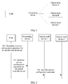
- FIG. 1 shows a possible D-CCAP applicable to a service parameter configuration method based on a D-CCAP according to an embodiment of this application.
- An architecture of the D-CCAP includes: an EMS, a forwarding device, and at least one optical node device.
- the EMS is configured to: determine a plurality of optical node device sets, determine a service configuration parameter for each optical node device set, and send the service configuration parameter for each optical node device set to the forwarding device.
- Each optical node device set includes at least one optical node device.
- an optical node device set may include an optical node device A and an optical node device B shown in FIG. 1
- another optical node device set may include the optical node device A and an optical node device C shown in FIG. 1 .
- the forwarding device is configured to: receive the service configuration parameter that is sent by the EMS for any optical node device set, and then, send the service configuration parameter to each optical node device in the optical node device set. For example, when the optical node device set includes the optical node device A and the optical node device B shown in FIG. 1 , the forwarding device sends the service configuration parameter separately to the optical node device A and the optical node device B.
- the at least one optical node device is configured to complete service parameter configuration of itself based on the received corresponding service configuration parameter sent by the forwarding device.
- the EMS performs service parameter configuration for the optical node device set, and the at least one optical node device in the optical node device set may share the service configuration parameter.
- the EMS does not need to perform service parameter configuration for all of a large quantity of optical node devices one by one, thereby reducing a quantity of service parameter configuration times, shortening a consumed time, and improving service parameter configuration efficiency.
- Step 201 An EMS determines a service configuration parameter for an optical node device set, where the optical node device set includes at least one optical node device.
- the service configuration parameter may be but is not limited to a service name, a user name, a password, output power, channel configuration information, or the like.
- the EMS may determine the service configuration parameter for the optical node device set in the following two manners:
- the EMS determines a plurality of optical node device sets based on service types, and determines, as one optical node device set, at least one optical node device that provides a same type of service. For example, the EMS determines, as the optical node device set, at least one optical node device that provides a digital television service (or a VoD service, or an FM broadcast service). Alternatively, the EMS may determine, as the optical node device set based on different areas of a same type of service, at least one optical node device that provides the service in a same area. For example, the EMS determines, as the optical node device set, at least one optical node device that provides a VoD service in an A area (or a B area).
- the EMS determines a service configuration parameter for each optical node device set based on a service requirement. For example, when an optical node device set requires a VoD service, the EMS determines that a service configuration parameter for the optical node device set is a VoD service parameter.
- the EMS obtains the stored service configuration parameter for the optical node device set.
- the EMS determines the service configuration parameter for the optical node device set.
- the EMS can perform service parameter configuration for the at least one optical node device in the optical node device set, instead of performing service parameter configuration for the at least one optical node device one by one, thereby reducing a quantity of service parameter configuration times, shortening a consumed time, and improving service parameter configuration efficiency.
- the EMS after determining the plurality of optical node device sets, the EMS sends information about the optical node device sets to the forwarding device, where the information about the optical node device sets includes a correspondence between each optical node device set and included at least one optical node device.
- Step 202 The EMS sends the service configuration parameter for the optical node device set to a forwarding device, so that the forwarding device sends the service configuration parameter to each of the at least one optical node device.
- An IP address of the forwarding device is configured in the EMS, an IP address of the EMS is configured in the forwarding device, and the EMS and the forwarding device may communicate by establishing a connection by using the configured IP addresses.
- the EMS may encapsulate the service configuration parameter into an IP packet, configure a destination IP address of the IP packet as the IP address of the forwarding device, and finally send the IP packet to the forwarding device.
- Step 203 The forwarding device sends the service configuration parameter to each of the at least one optical node device.
- the forwarding device determines a target optical node device based on the information about the optical node device sets, and sends the service configuration parameter to the target optical node device.
- the forwarding device performs step 203 in the following two steps:
- the forwarding device may send the service configuration parameter to the optical node device through the target port connected to the optical node device.
- a service configuration parameter is transmitted between the forwarding device and each optical node device by using a corresponding port, and the service configuration parameter does not need to be transmitted by using an independent IP address of each optical node device.
- the EMS does not need to configure an IP address for the optical node device. This resolves a problem that IP address resources are limited due to excessively large consumption of IP addresses, thereby saving the IP address resources.
- the forwarding device further performs the following three steps:
- the forwarding device centrally reports the running data to the EMS.
- the forwarding device may perform step a1 in the following three manners:
- the forwarding device actively obtains the running data of the plurality of optical node devices. For example, when the user needs to monitor the running data of the plurality of optical node devices by using the EMS, the EMS delivers the instruction for obtaining the running data to the forwarding device, so that the forwarding device actively obtains the running data of the plurality of optical node devices.
- the forwarding device actively obtains the running data of the plurality of optical node devices according to a first specified period.
- the forwarding device receives the running data that is reported by the plurality of optical node devices according to a second specified period.
- the plurality of optical node devices may send running data of a specified quantity of optical node devices, or may send running data of a specified type of service on the plurality of optical node devices.
- a specific method may be as follows: The forwarding device performs classification and integration processing on the running data to obtain processed running data. For example, the forwarding device performs classification processing on the running data of the plurality of optical node devices based on different service types, and then, integrates the running data of all the optical node devices that provide a same type of service. In this way, after the EMS receives the processed running data, running statuses of the plurality of optical node devices may be directly perceived, thereby improving monitoring performance.
- the forwarding device generates a running data file that includes the processed running data.
- a format of the running data file may be a specified file format, and the specified format may be a format agreed on by the EMS and the forwarding device based on a service requirement.
- the forwarding device when the forwarding device performs step c1, specifically, there may be the following two cases: In a first case, after receiving an instruction for obtaining running status data, the forwarding device sends the data file to the EMS.
- the forwarding device sends the data file to the EMS according to a third specified period.
- a setting interface may be set between the EMS and the forwarding device, so that the EMS transmits agreed data to the forwarding device by using the setting interface.
- the EMS transmits the service configuration parameter to the forwarding device, and the forwarding device transmits the running data file to the EMS.
- the EMS determines the service configuration parameter for the optical node device set, where the optical node device set includes the at least one optical node device; and sends the service configuration parameter for the optical node device set to the forwarding device, so that the forwarding device sends the service configuration parameter to each of the at least one optical node device.
- the at least one optical node device in the optical node device set may share a service configuration parameter. In this way, the EMS does not need to perform service parameter configuration for all of a large quantity of optical node devices one by one, thereby reducing a quantity of service parameter configuration times, shortening a consumed time, and improving service parameter configuration efficiency.
- an embodiment of this application further provides an EMS.
- the EMS is applied to the D-CCAP shown in FIG. 1 , and is used to implement the service parameter configuration method based on a D-CCAP shown in FIG. 2 .
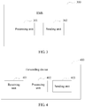
- an EMS 300 includes a processing unit 301 and a sending unit 302.
- the processing unit 301 is configured to determine a service configuration parameter for an optical node device set, where the optical node device set includes at least one optical node device.
- the sending unit 302 is configured to send the service configuration parameter for the optical node device set to a forwarding device, so that the forwarding device sends the service configuration parameter to each of the at least one optical node device.
- the processing unit 301 when determining the service configuration parameter for the optical node device set, is specifically configured to:
- the EMS 300 further includes: a receiving unit, configured to: after the sending unit 302 sends the service configuration parameter for the optical node device set to the forwarding device, receive a running data file sent by the forwarding device, where the data file includes running data of a plurality of optical node devices.
- a receiving unit configured to: after the sending unit 302 sends the service configuration parameter for the optical node device set to the forwarding device, receive a running data file sent by the forwarding device, where the data file includes running data of a plurality of optical node devices.
- the EMS provided in this embodiment of this application determines the service configuration parameter for the optical node device set, where the optical node device set includes at least one optical node device; and sends the service configuration parameter for the optical node device set to the forwarding device, so that the forwarding device sends the service configuration parameter to each of the at least one optical node device.
- the at least one optical node device in the optical node device set may share a service configuration parameter.
- the EMS does not need to perform service parameter configuration for all of a large quantity of optical node devices one by one, thereby reducing a quantity of service parameter configuration times, shortening a consumed time, and improving service parameter configuration efficiency.
- an embodiment of this application further provides a forwarding device.
- the forwarding device is applied to the D-CCAP shown in FIG. 1 , and is configured to implement the service parameter configuration method based on a D-CCAP shown in FIG. 2 .
- a forwarding device 400 includes a receiving unit 401, a processing unit 402, and a sending unit 403.
- the receiving unit 401 is configured to receive a service configuration parameter that is sent by an EMS for an optical node device set, where the optical node device set includes at least one optical node device.
- the processing unit 402 is configured to control the sending unit 403 to send the service configuration parameter to each of the at least one optical node device.
- the sending unit 403 is configured to send the service configuration parameter to each of the at least one optical node device.
- processing unit 402 is specifically configured to:
- the receiving unit 401 is further configured to: after the sending unit 403 sends the service configuration parameter to each of the at least one optical node device, obtain running data of a plurality of optical node devices.
- the processing unit 402 is further configured to:
- the sending unit 403 is further configured to send the running data file to the EMS.
- the forwarding device receives the service configuration parameter that is sent by the EMS for the optical node device set, and then, sends the service configuration parameter to each of at least one optical node device included in the optical node device set.
- the at least one optical node device in the optical node device set may share a service configuration parameter.
- the EMS does not need to perform service parameter configuration for all of a large quantity of optical node devices one by one, thereby reducing a quantity of service parameter configuration times, shortening a consumed time, and improving service parameter configuration efficiency.
- unit division in the embodiments of this application is an example and is merely logical function division. During actual implementation, there may be another division manner.
- Functional units in the embodiments of this application may be integrated into one processing unit, or each of the units may exist alone physically, or two or more units are integrated into one unit.
- the foregoing integrated unit may be implemented in a form of hardware, or may be implemented in a form of a software functional unit.
- the integrated unit When the integrated unit is implemented in the form of a software functional unit and sold or used as an independent product, the integrated unit may be stored in a computer-readable storage medium. Based on such an understanding, the technical solutions of this application essentially, or the part contributing to the prior art, or all or some of the technical solutions may be implemented in the form of a software product.
- the computer software product is stored in a storage medium and includes several instructions for instructing a computer device (which may be a personal computer, a server, a network device, or the like) or a processor (processor) to perform all or some of the steps of the methods described in the embodiments of this application.
- the foregoing storage medium includes: any medium that can store program code, such as a USB flash drive, a removable hard disk, a read-only memory (ROM, Read-Only Memory), a random access memory (RAM, Random Access Memory), a magnetic disk, or an optical disc.
- program code such as a USB flash drive, a removable hard disk, a read-only memory (ROM, Read-Only Memory), a random access memory (RAM, Random Access Memory), a magnetic disk, or an optical disc.
- an embodiment of this application further provides an EMS.
- the EMS is applied to the D-CCAP shown in FIG. 1 .
- the D-CCAP further includes a forwarding device.
- an EMS 500 includes a transceiver 501, a processor 502, a bus 503, and a memory 504.
- the transceiver 501, the processor 502, and the memory 504 are connected to each other by using the bus 503.
- the bus 503 may be a Peripheral Component Interconnect (peripheral component interconnect, PCI) bus, an extended industry standard architecture (extended industry standard architecture, EISA) bus, or the like.
- PCI Peripheral Component Interconnect
- EISA extended industry standard architecture
- the bus may be classified into an address bus, a data bus, a control bus, and the like. For ease of representation, only one thick line is used to represent the bus in FIG. 5 , but this does not mean that there is only one bus or only one type of bus.
- the transceiver 501 is configured to perform communication interaction with another device, in the D-CCAP, connected to the EMS 500.
- the processor 502 is configured to implement the service parameter configuration method based on a D-CCAP shown in FIG. 2 .
- the service parameter configuration method based on a D-CCAP includes:
- the processor 502 when determining the service configuration parameter for the optical node device set, is specifically configured to:
- the processor 502 is further configured to: after the service configuration parameter for the optical node device set is sent to the forwarding device, receive a running data file sent by the forwarding device, where the data file includes running data of a plurality of optical node devices.
- the memory 504 is configured to store a program and the like.
- the program may include program code, and the program code includes a computer operation instruction.
- the memory 504 may include a RAM, and may further include a non-volatile memory (non-volatile memory) such as at least one magnetic disk memory.
- the processor 502 executes the application program stored in the memory 504, to implement the foregoing function, so as to implement the service parameter configuration method based on a D-CCAP shown in FIG. 2 .
- the EMS provided in this embodiment of this application determines the service configuration parameter for the optical node device set, where the optical node device set includes at least one optical node device; and sends the service configuration parameter for the optical node device set to the forwarding device, so that the forwarding device sends the service configuration parameter to each of the at least one optical node device.
- the at least one optical node device in the optical node device set may share a service configuration parameter.
- the EMS does not need to perform service parameter configuration for all of a large quantity of optical node devices one by one, thereby reducing a quantity of service parameter configuration times, shortening a consumed time, and improving service parameter configuration efficiency.
- an embodiment of this application further provides a forwarding device.
- the forwarding device is applied to the D-CCAP shown in FIG. 1 .
- the D-CCAP further includes an EMS.
- a forwarding device 600 includes a transceiver 601, a processor 602, a bus 603, and a memory 604.
- the transceiver 601, the processor 602, and the memory 604 are connected to each other by using the bus 603.
- the bus 603 may be a Peripheral Component Interconnect (peripheral component interconnect, PCI) bus, an extended industry standard architecture (extended industry standard architecture, EISA) bus, or the like.
- PCI Peripheral Component Interconnect
- EISA extended industry standard architecture
- the bus may be classified into an address bus, a data bus, a control bus, and the like. For ease of representation, only one thick line is used to represent the bus in FIG. 6 , but this does not mean that there is only one bus or only one type of bus.
- the transceiver 601 is configured to perform communication interaction with another device, in the D-CCAP, connected to the forwarding device 600.
- the processor 602 is configured to implement the service parameter configuration method based on a D-CCAP shown in FIG. 2 .
- the service parameter configuration method based on a D-CCAP includes: receiving a service configuration parameter that is sent by an EMS for an optical node device set, where the optical node device set includes at least one optical node device; and then, sending the service configuration parameter to each of at least one optical node device included in the optical node device set.
- the processor 602 when the service configuration parameter is sent to each of the at least one optical node device, the processor 602 is specifically configured to:
- processor 602 is further configured to:
- the memory 604 is configured to store a program and the like.
- the program may include program code, and the program code includes a computer operation instruction.
- the memory 604 may include a RAM, and may further include a non-volatile memory (non-volatile memory) such as at least one magnetic disk memory.
- the processor 602 executes the application program stored in the memory 604, to implement the foregoing function, so as to implement the service parameter configuration method based on a D-CCAP shown in FIG. 2 .
- the forwarding device receives the service configuration parameter that is sent by the EMS for the optical node device set, and then, sends the service configuration parameter to each of at least one optical node device included in the optical node device set.
- the at least one optical node device in the optical node device set may share a service configuration parameter.
- the EMS does not need to perform service parameter configuration for all of a large quantity of optical node devices one by one, thereby reducing a quantity of service parameter configuration times, shortening a consumed time, and improving service parameter configuration efficiency.
- the EMS determines the service configuration parameter for the optical node device set, where the optical node device set includes the at least one optical node device; and sends the service configuration parameter for the optical node device set to the forwarding device, so that the forwarding device sends the service configuration parameter to each of the at least one optical node device.
- the at least one optical node device in the optical node device set may share a service configuration parameter. In this way, the EMS does not need to perform service parameter configuration for all of a large quantity of optical node devices one by one, thereby reducing a quantity of service parameter configuration times, shortening a consumed time, and improving service parameter configuration efficiency.
- this application may be provided as a method, a system, or a computer program product. Therefore, this application may use a form of hardware only embodiments, software only embodiments, or embodiments with a combination of software and hardware. Moreover, this application may use a form of a computer program product that is implemented on one or more computer-usable storage media (including but not limited to a disk memory, a CD-ROM, an optical memory, and the like) that include computer usable program code.
- a computer-usable storage media including but not limited to a disk memory, a CD-ROM, an optical memory, and the like
- These computer program instructions may be provided for a general-purpose computer, a dedicated computer, an embedded processor, or a processor of any other programmable data processing device to generate a machine, so that the instructions executed by a computer or a processor of any other programmable data processing device generate an apparatus for implementing a specific function in one or more processes in the flowcharts and/or in one or more blocks in the block diagrams.
- These computer program instructions may be stored in a computer readable memory that can instruct the computer or any other programmable data processing device to work in a specific manner, so that the instructions stored in the computer readable memory generate an artifact that includes an instruction apparatus.
- the instruction apparatus implements a specific function in one or more processes in the flowcharts and/or in one or more blocks in the block diagrams.
- These computer program instructions may be loaded onto a computer or another programmable data processing device, so that a series of operations and steps are performed on the computer or the another programmable device, thereby generating computer-implemented processing. Therefore, the instructions executed on the computer or the another programmable device provide steps for implementing a specific function in one or more processes in the flowcharts and/or in one or more blocks in the block diagrams.
Landscapes
- Engineering & Computer Science (AREA)
- Computer Networks & Wireless Communication (AREA)
- Signal Processing (AREA)
- Computing Systems (AREA)
- Physics & Mathematics (AREA)
- Electromagnetism (AREA)
- Data Exchanges In Wide-Area Networks (AREA)
- Optical Communication System (AREA)
Applications Claiming Priority (1)
| Application Number | Priority Date | Filing Date | Title |
|---|---|---|---|
| PCT/CN2017/071944 WO2018133033A1 (zh) | 2017-01-20 | 2017-01-20 | 一种基于d-ccap的业务参数配置方法及装置 |
Publications (3)
| Publication Number | Publication Date |
|---|---|
| EP3537659A1 true EP3537659A1 (de) | 2019-09-11 |
| EP3537659A4 EP3537659A4 (de) | 2019-11-20 |
| EP3537659B1 EP3537659B1 (de) | 2020-12-02 |
Family
ID=62907607
Family Applications (1)
| Application Number | Title | Priority Date | Filing Date |
|---|---|---|---|
| EP17892744.8A Active EP3537659B1 (de) | 2017-01-20 | 2017-01-20 | Verfahren und vorrichtung zur konfiguration von d-ccap-basierten dienstparametern |
Country Status (3)
| Country | Link |
|---|---|
| EP (1) | EP3537659B1 (de) |
| CN (1) | CN109565450A (de) |
| WO (1) | WO2018133033A1 (de) |
Family Cites Families (5)
| Publication number | Priority date | Publication date | Assignee | Title |
|---|---|---|---|---|
| CN101247258B (zh) * | 2007-02-12 | 2011-02-09 | 华为技术有限公司 | 一种业务发放方法及系统 |
| CN101534155B (zh) * | 2007-02-12 | 2012-05-30 | 华为技术有限公司 | 一种业务发放方法及系统 |
| US20080253771A1 (en) * | 2007-04-13 | 2008-10-16 | Noel Jeffrey A | Method and apparatus for configuring Optical Network Terminals (ONT) in a network |
| CN102104420A (zh) * | 2009-12-22 | 2011-06-22 | 华为技术有限公司 | 光网络终端的参数配置方法、装置和系统 |
| CN102868545B (zh) * | 2011-07-07 | 2017-08-01 | 南京中兴新软件有限责任公司 | 无源光网络的配置方法和网元管理系统 |
-
2017
- 2017-01-20 WO PCT/CN2017/071944 patent/WO2018133033A1/zh not_active Ceased
- 2017-01-20 CN CN201780050504.6A patent/CN109565450A/zh active Pending
- 2017-01-20 EP EP17892744.8A patent/EP3537659B1/de active Active
Also Published As
| Publication number | Publication date |
|---|---|
| CN109565450A (zh) | 2019-04-02 |
| EP3537659B1 (de) | 2020-12-02 |
| EP3537659A4 (de) | 2019-11-20 |
| WO2018133033A1 (zh) | 2018-07-26 |
Similar Documents
| Publication | Publication Date | Title |
|---|---|---|
| US11228947B2 (en) | Network slice deployment method and related device | |
| US12113667B2 (en) | Network slice configuration method, apparatus, and system | |
| US10694389B2 (en) | Network slice management method, management unit, and system | |
| US11894992B2 (en) | Network component management method and network device | |
| EP3043522B1 (de) | Datenpaketverarbeitungsverfahren sowie verfahren, vorrichtung und system zur netzwerkverkehrsverwaltung | |
| JP2020511083A (ja) | サービス品質制御方法およびその装置、smf、upf、ue、pcfおよびan | |
| CN110061871A (zh) | 基站开站方法、装置、计算机存储介质及设备 | |
| US11418385B2 (en) | Network alarm method, device, system and terminal | |
| US20190238949A1 (en) | Multicast service providing method and software defined networking controller | |
| US20200177462A1 (en) | Service Management Method and Apparatus, and Storage Medium | |
| CN109040178B (zh) | 配置信息发送方法及装置 | |
| US11516110B2 (en) | Method and apparatus for obtaining cross-domain link | |
| US20180062946A1 (en) | Method and Apparatus for Establishing Network Service Instance | |
| CN112449301B (zh) | 一种定位辅助信息的广播方法、定位服务器及ran节点 | |
| CN108781215B (zh) | 网络服务实现方法、服务控制器及通信系统 | |
| EP3537659B1 (de) | Verfahren und vorrichtung zur konfiguration von d-ccap-basierten dienstparametern | |
| EP3503484A1 (de) | Nachrichtenübertragungsverfahren, vorrichtung und netzwerksystem | |
| US11452000B2 (en) | Method for reporting data volume of data duplication, user equipment, and network device | |
| EP3065445A1 (de) | Verfahren, cse und system zur übertragung einer m2m-anwendungsanfrage | |
| CN111147269A (zh) | 接入点配置方法、组网系统、接入点和存储介质 | |
| CN116095162A (zh) | 多播通信方法、电子设备及计算机可读存储介质 | |
| CN113905401A (zh) | 一种子切片对接方法、装置及设备 | |
| CN116318473B (zh) | 一种LoRa信道动态调整方法、装置、设备及介质 | |
| US20180176085A1 (en) | Automated service delivery based on automated identifier discovery | |
| CN108064088A (zh) | Rrc连接释放方法、终端、接入网设备及存储介质 |
Legal Events
| Date | Code | Title | Description |
|---|---|---|---|
| STAA | Information on the status of an ep patent application or granted ep patent |
Free format text: STATUS: THE INTERNATIONAL PUBLICATION HAS BEEN MADE |
|
| PUAI | Public reference made under article 153(3) epc to a published international application that has entered the european phase |
Free format text: ORIGINAL CODE: 0009012 |
|
| STAA | Information on the status of an ep patent application or granted ep patent |
Free format text: STATUS: REQUEST FOR EXAMINATION WAS MADE |
|
| 17P | Request for examination filed |
Effective date: 20190606 |
|
| AK | Designated contracting states |
Kind code of ref document: A1 Designated state(s): AL AT BE BG CH CY CZ DE DK EE ES FI FR GB GR HR HU IE IS IT LI LT LU LV MC MK MT NL NO PL PT RO RS SE SI SK SM TR |
|
| AX | Request for extension of the european patent |
Extension state: BA ME |
|
| A4 | Supplementary search report drawn up and despatched |
Effective date: 20191018 |
|
| RIC1 | Information provided on ipc code assigned before grant |
Ipc: H04L 12/24 20060101AFI20191014BHEP Ipc: H04Q 11/00 20060101ALI20191014BHEP Ipc: H04B 10/27 20130101ALI20191014BHEP |
|
| DAV | Request for validation of the european patent (deleted) | ||
| DAX | Request for extension of the european patent (deleted) | ||
| GRAP | Despatch of communication of intention to grant a patent |
Free format text: ORIGINAL CODE: EPIDOSNIGR1 |
|
| STAA | Information on the status of an ep patent application or granted ep patent |
Free format text: STATUS: GRANT OF PATENT IS INTENDED |
|
| INTG | Intention to grant announced |
Effective date: 20200731 |
|
| GRAS | Grant fee paid |
Free format text: ORIGINAL CODE: EPIDOSNIGR3 |
|
| GRAA | (expected) grant |
Free format text: ORIGINAL CODE: 0009210 |
|
| STAA | Information on the status of an ep patent application or granted ep patent |
Free format text: STATUS: THE PATENT HAS BEEN GRANTED |
|
| AK | Designated contracting states |
Kind code of ref document: B1 Designated state(s): AL AT BE BG CH CY CZ DE DK EE ES FI FR GB GR HR HU IE IS IT LI LT LU LV MC MK MT NL NO PL PT RO RS SE SI SK SM TR |
|
| REG | Reference to a national code |
Ref country code: GB Ref legal event code: FG4D |
|
| REG | Reference to a national code |
Ref country code: AT Ref legal event code: REF Ref document number: 1342133 Country of ref document: AT Kind code of ref document: T Effective date: 20201215 Ref country code: CH Ref legal event code: EP |
|
| REG | Reference to a national code |
Ref country code: IE Ref legal event code: FG4D |
|
| REG | Reference to a national code |
Ref country code: DE Ref legal event code: R096 Ref document number: 602017029062 Country of ref document: DE |
|
| PG25 | Lapsed in a contracting state [announced via postgrant information from national office to epo] |
Ref country code: NO Free format text: LAPSE BECAUSE OF FAILURE TO SUBMIT A TRANSLATION OF THE DESCRIPTION OR TO PAY THE FEE WITHIN THE PRESCRIBED TIME-LIMIT Effective date: 20210302 Ref country code: GR Free format text: LAPSE BECAUSE OF FAILURE TO SUBMIT A TRANSLATION OF THE DESCRIPTION OR TO PAY THE FEE WITHIN THE PRESCRIBED TIME-LIMIT Effective date: 20210303 Ref country code: RS Free format text: LAPSE BECAUSE OF FAILURE TO SUBMIT A TRANSLATION OF THE DESCRIPTION OR TO PAY THE FEE WITHIN THE PRESCRIBED TIME-LIMIT Effective date: 20201202 Ref country code: FI Free format text: LAPSE BECAUSE OF FAILURE TO SUBMIT A TRANSLATION OF THE DESCRIPTION OR TO PAY THE FEE WITHIN THE PRESCRIBED TIME-LIMIT Effective date: 20201202 |
|
| REG | Reference to a national code |
Ref country code: NL Ref legal event code: MP Effective date: 20201202 |
|
| REG | Reference to a national code |
Ref country code: AT Ref legal event code: MK05 Ref document number: 1342133 Country of ref document: AT Kind code of ref document: T Effective date: 20201202 |
|
| PG25 | Lapsed in a contracting state [announced via postgrant information from national office to epo] |
Ref country code: BG Free format text: LAPSE BECAUSE OF FAILURE TO SUBMIT A TRANSLATION OF THE DESCRIPTION OR TO PAY THE FEE WITHIN THE PRESCRIBED TIME-LIMIT Effective date: 20210302 Ref country code: SE Free format text: LAPSE BECAUSE OF FAILURE TO SUBMIT A TRANSLATION OF THE DESCRIPTION OR TO PAY THE FEE WITHIN THE PRESCRIBED TIME-LIMIT Effective date: 20201202 Ref country code: LV Free format text: LAPSE BECAUSE OF FAILURE TO SUBMIT A TRANSLATION OF THE DESCRIPTION OR TO PAY THE FEE WITHIN THE PRESCRIBED TIME-LIMIT Effective date: 20201202 Ref country code: PL Free format text: LAPSE BECAUSE OF FAILURE TO SUBMIT A TRANSLATION OF THE DESCRIPTION OR TO PAY THE FEE WITHIN THE PRESCRIBED TIME-LIMIT Effective date: 20201202 |
|
| PG25 | Lapsed in a contracting state [announced via postgrant information from national office to epo] |
Ref country code: NL Free format text: LAPSE BECAUSE OF FAILURE TO SUBMIT A TRANSLATION OF THE DESCRIPTION OR TO PAY THE FEE WITHIN THE PRESCRIBED TIME-LIMIT Effective date: 20201202 Ref country code: HR Free format text: LAPSE BECAUSE OF FAILURE TO SUBMIT A TRANSLATION OF THE DESCRIPTION OR TO PAY THE FEE WITHIN THE PRESCRIBED TIME-LIMIT Effective date: 20201202 |
|
| REG | Reference to a national code |
Ref country code: LT Ref legal event code: MG9D |
|
| PG25 | Lapsed in a contracting state [announced via postgrant information from national office to epo] |
Ref country code: EE Free format text: LAPSE BECAUSE OF FAILURE TO SUBMIT A TRANSLATION OF THE DESCRIPTION OR TO PAY THE FEE WITHIN THE PRESCRIBED TIME-LIMIT Effective date: 20201202 Ref country code: CZ Free format text: LAPSE BECAUSE OF FAILURE TO SUBMIT A TRANSLATION OF THE DESCRIPTION OR TO PAY THE FEE WITHIN THE PRESCRIBED TIME-LIMIT Effective date: 20201202 Ref country code: LT Free format text: LAPSE BECAUSE OF FAILURE TO SUBMIT A TRANSLATION OF THE DESCRIPTION OR TO PAY THE FEE WITHIN THE PRESCRIBED TIME-LIMIT Effective date: 20201202 Ref country code: SM Free format text: LAPSE BECAUSE OF FAILURE TO SUBMIT A TRANSLATION OF THE DESCRIPTION OR TO PAY THE FEE WITHIN THE PRESCRIBED TIME-LIMIT Effective date: 20201202 Ref country code: RO Free format text: LAPSE BECAUSE OF FAILURE TO SUBMIT A TRANSLATION OF THE DESCRIPTION OR TO PAY THE FEE WITHIN THE PRESCRIBED TIME-LIMIT Effective date: 20201202 Ref country code: SK Free format text: LAPSE BECAUSE OF FAILURE TO SUBMIT A TRANSLATION OF THE DESCRIPTION OR TO PAY THE FEE WITHIN THE PRESCRIBED TIME-LIMIT Effective date: 20201202 Ref country code: PT Free format text: LAPSE BECAUSE OF FAILURE TO SUBMIT A TRANSLATION OF THE DESCRIPTION OR TO PAY THE FEE WITHIN THE PRESCRIBED TIME-LIMIT Effective date: 20210405 |
|
| PG25 | Lapsed in a contracting state [announced via postgrant information from national office to epo] |
Ref country code: AT Free format text: LAPSE BECAUSE OF FAILURE TO SUBMIT A TRANSLATION OF THE DESCRIPTION OR TO PAY THE FEE WITHIN THE PRESCRIBED TIME-LIMIT Effective date: 20201202 |
|
| REG | Reference to a national code |
Ref country code: CH Ref legal event code: PL |
|
| REG | Reference to a national code |
Ref country code: DE Ref legal event code: R097 Ref document number: 602017029062 Country of ref document: DE |
|
| PG25 | Lapsed in a contracting state [announced via postgrant information from national office to epo] |
Ref country code: MC Free format text: LAPSE BECAUSE OF FAILURE TO SUBMIT A TRANSLATION OF THE DESCRIPTION OR TO PAY THE FEE WITHIN THE PRESCRIBED TIME-LIMIT Effective date: 20201202 Ref country code: IS Free format text: LAPSE BECAUSE OF FAILURE TO SUBMIT A TRANSLATION OF THE DESCRIPTION OR TO PAY THE FEE WITHIN THE PRESCRIBED TIME-LIMIT Effective date: 20210402 Ref country code: LU Free format text: LAPSE BECAUSE OF NON-PAYMENT OF DUE FEES Effective date: 20210120 |
|
| REG | Reference to a national code |
Ref country code: BE Ref legal event code: MM Effective date: 20210131 |
|
| PLBE | No opposition filed within time limit |
Free format text: ORIGINAL CODE: 0009261 |
|
| STAA | Information on the status of an ep patent application or granted ep patent |
Free format text: STATUS: NO OPPOSITION FILED WITHIN TIME LIMIT |
|
| PG25 | Lapsed in a contracting state [announced via postgrant information from national office to epo] |
Ref country code: IT Free format text: LAPSE BECAUSE OF FAILURE TO SUBMIT A TRANSLATION OF THE DESCRIPTION OR TO PAY THE FEE WITHIN THE PRESCRIBED TIME-LIMIT Effective date: 20201202 Ref country code: FR Free format text: LAPSE BECAUSE OF NON-PAYMENT OF DUE FEES Effective date: 20210202 Ref country code: AL Free format text: LAPSE BECAUSE OF FAILURE TO SUBMIT A TRANSLATION OF THE DESCRIPTION OR TO PAY THE FEE WITHIN THE PRESCRIBED TIME-LIMIT Effective date: 20201202 |
|
| 26N | No opposition filed |
Effective date: 20210903 |
|
| REG | Reference to a national code |
Ref country code: DE Ref legal event code: R079 Ref document number: 602017029062 Country of ref document: DE Free format text: PREVIOUS MAIN CLASS: H04L0012240000 Ipc: H04L0041000000 |
|
| PG25 | Lapsed in a contracting state [announced via postgrant information from national office to epo] |
Ref country code: SI Free format text: LAPSE BECAUSE OF FAILURE TO SUBMIT A TRANSLATION OF THE DESCRIPTION OR TO PAY THE FEE WITHIN THE PRESCRIBED TIME-LIMIT Effective date: 20201202 Ref country code: DK Free format text: LAPSE BECAUSE OF FAILURE TO SUBMIT A TRANSLATION OF THE DESCRIPTION OR TO PAY THE FEE WITHIN THE PRESCRIBED TIME-LIMIT Effective date: 20201202 Ref country code: CH Free format text: LAPSE BECAUSE OF NON-PAYMENT OF DUE FEES Effective date: 20210131 Ref country code: LI Free format text: LAPSE BECAUSE OF NON-PAYMENT OF DUE FEES Effective date: 20210131 |
|
| PG25 | Lapsed in a contracting state [announced via postgrant information from national office to epo] |
Ref country code: IE Free format text: LAPSE BECAUSE OF NON-PAYMENT OF DUE FEES Effective date: 20210120 Ref country code: ES Free format text: LAPSE BECAUSE OF FAILURE TO SUBMIT A TRANSLATION OF THE DESCRIPTION OR TO PAY THE FEE WITHIN THE PRESCRIBED TIME-LIMIT Effective date: 20201202 |
|
| PG25 | Lapsed in a contracting state [announced via postgrant information from national office to epo] |
Ref country code: IS Free format text: LAPSE BECAUSE OF FAILURE TO SUBMIT A TRANSLATION OF THE DESCRIPTION OR TO PAY THE FEE WITHIN THE PRESCRIBED TIME-LIMIT Effective date: 20210402 |
|
| PG25 | Lapsed in a contracting state [announced via postgrant information from national office to epo] |
Ref country code: BE Free format text: LAPSE BECAUSE OF NON-PAYMENT OF DUE FEES Effective date: 20210131 |
|
| PG25 | Lapsed in a contracting state [announced via postgrant information from national office to epo] |
Ref country code: CY Free format text: LAPSE BECAUSE OF FAILURE TO SUBMIT A TRANSLATION OF THE DESCRIPTION OR TO PAY THE FEE WITHIN THE PRESCRIBED TIME-LIMIT Effective date: 20201202 |
|
| PG25 | Lapsed in a contracting state [announced via postgrant information from national office to epo] |
Ref country code: HU Free format text: LAPSE BECAUSE OF FAILURE TO SUBMIT A TRANSLATION OF THE DESCRIPTION OR TO PAY THE FEE WITHIN THE PRESCRIBED TIME-LIMIT; INVALID AB INITIO Effective date: 20170120 |
|
| PG25 | Lapsed in a contracting state [announced via postgrant information from national office to epo] |
Ref country code: MK Free format text: LAPSE BECAUSE OF FAILURE TO SUBMIT A TRANSLATION OF THE DESCRIPTION OR TO PAY THE FEE WITHIN THE PRESCRIBED TIME-LIMIT Effective date: 20201202 |
|
| PG25 | Lapsed in a contracting state [announced via postgrant information from national office to epo] |
Ref country code: MT Free format text: LAPSE BECAUSE OF FAILURE TO SUBMIT A TRANSLATION OF THE DESCRIPTION OR TO PAY THE FEE WITHIN THE PRESCRIBED TIME-LIMIT Effective date: 20201202 |
|
| PG25 | Lapsed in a contracting state [announced via postgrant information from national office to epo] |
Ref country code: TR Free format text: LAPSE BECAUSE OF FAILURE TO SUBMIT A TRANSLATION OF THE DESCRIPTION OR TO PAY THE FEE WITHIN THE PRESCRIBED TIME-LIMIT Effective date: 20201202 |
|
| PGFP | Annual fee paid to national office [announced via postgrant information from national office to epo] |
Ref country code: GB Payment date: 20251204 Year of fee payment: 10 |
|
| PGFP | Annual fee paid to national office [announced via postgrant information from national office to epo] |
Ref country code: DE Payment date: 20251203 Year of fee payment: 10 |