EP3537705A1 - Perche à selfie et procédé de commande de dispositif de photographie au moyen d'une perche à selfie - Google Patents
Perche à selfie et procédé de commande de dispositif de photographie au moyen d'une perche à selfie Download PDFInfo
- Publication number
- EP3537705A1 EP3537705A1 EP17868138.3A EP17868138A EP3537705A1 EP 3537705 A1 EP3537705 A1 EP 3537705A1 EP 17868138 A EP17868138 A EP 17868138A EP 3537705 A1 EP3537705 A1 EP 3537705A1
- Authority
- EP
- European Patent Office
- Prior art keywords
- selfie stick
- photographic device
- touch screen
- handle
- flexible touch
- Prior art date
- Legal status (The legal status is an assumption and is not a legal conclusion. Google has not performed a legal analysis and makes no representation as to the accuracy of the status listed.)
- Withdrawn
Links
Images







Classifications
-
- H—ELECTRICITY
- H04—ELECTRIC COMMUNICATION TECHNIQUE
- H04N—PICTORIAL COMMUNICATION, e.g. TELEVISION
- H04N23/00—Cameras or camera modules comprising electronic image sensors; Control thereof
- H04N23/60—Control of cameras or camera modules
- H04N23/66—Remote control of cameras or camera parts, e.g. by remote control devices
-
- G—PHYSICS
- G03—PHOTOGRAPHY; CINEMATOGRAPHY; ANALOGOUS TECHNIQUES USING WAVES OTHER THAN OPTICAL WAVES; ELECTROGRAPHY; HOLOGRAPHY
- G03B—APPARATUS OR ARRANGEMENTS FOR TAKING PHOTOGRAPHS OR FOR PROJECTING OR VIEWING THEM; APPARATUS OR ARRANGEMENTS EMPLOYING ANALOGOUS TECHNIQUES USING WAVES OTHER THAN OPTICAL WAVES; ACCESSORIES THEREFOR
- G03B17/00—Details of cameras or camera bodies; Accessories therefor
- G03B17/56—Accessories
- G03B17/561—Support related camera accessories
-
- F—MECHANICAL ENGINEERING; LIGHTING; HEATING; WEAPONS; BLASTING
- F16—ENGINEERING ELEMENTS AND UNITS; GENERAL MEASURES FOR PRODUCING AND MAINTAINING EFFECTIVE FUNCTIONING OF MACHINES OR INSTALLATIONS; THERMAL INSULATION IN GENERAL
- F16M—FRAMES, CASINGS OR BEDS OF ENGINES, MACHINES OR APPARATUS, NOT SPECIFIC TO ENGINES, MACHINES OR APPARATUS PROVIDED FOR ELSEWHERE; STANDS; SUPPORTS
- F16M11/00—Stands or trestles as supports for apparatus or articles placed thereon ; Stands for scientific apparatus such as gravitational force meters
- F16M11/02—Heads
- F16M11/04—Means for attachment of apparatus; Means allowing adjustment of the apparatus relatively to the stand
-
- F—MECHANICAL ENGINEERING; LIGHTING; HEATING; WEAPONS; BLASTING
- F16—ENGINEERING ELEMENTS AND UNITS; GENERAL MEASURES FOR PRODUCING AND MAINTAINING EFFECTIVE FUNCTIONING OF MACHINES OR INSTALLATIONS; THERMAL INSULATION IN GENERAL
- F16M—FRAMES, CASINGS OR BEDS OF ENGINES, MACHINES OR APPARATUS, NOT SPECIFIC TO ENGINES, MACHINES OR APPARATUS PROVIDED FOR ELSEWHERE; STANDS; SUPPORTS
- F16M11/00—Stands or trestles as supports for apparatus or articles placed thereon ; Stands for scientific apparatus such as gravitational force meters
- F16M11/02—Heads
- F16M11/04—Means for attachment of apparatus; Means allowing adjustment of the apparatus relatively to the stand
- F16M11/041—Allowing quick release of the apparatus
-
- F—MECHANICAL ENGINEERING; LIGHTING; HEATING; WEAPONS; BLASTING
- F16—ENGINEERING ELEMENTS AND UNITS; GENERAL MEASURES FOR PRODUCING AND MAINTAINING EFFECTIVE FUNCTIONING OF MACHINES OR INSTALLATIONS; THERMAL INSULATION IN GENERAL
- F16M—FRAMES, CASINGS OR BEDS OF ENGINES, MACHINES OR APPARATUS, NOT SPECIFIC TO ENGINES, MACHINES OR APPARATUS PROVIDED FOR ELSEWHERE; STANDS; SUPPORTS
- F16M11/00—Stands or trestles as supports for apparatus or articles placed thereon ; Stands for scientific apparatus such as gravitational force meters
- F16M11/02—Heads
- F16M11/04—Means for attachment of apparatus; Means allowing adjustment of the apparatus relatively to the stand
- F16M11/06—Means for attachment of apparatus; Means allowing adjustment of the apparatus relatively to the stand allowing pivoting
-
- F—MECHANICAL ENGINEERING; LIGHTING; HEATING; WEAPONS; BLASTING
- F16—ENGINEERING ELEMENTS AND UNITS; GENERAL MEASURES FOR PRODUCING AND MAINTAINING EFFECTIVE FUNCTIONING OF MACHINES OR INSTALLATIONS; THERMAL INSULATION IN GENERAL
- F16M—FRAMES, CASINGS OR BEDS OF ENGINES, MACHINES OR APPARATUS, NOT SPECIFIC TO ENGINES, MACHINES OR APPARATUS PROVIDED FOR ELSEWHERE; STANDS; SUPPORTS
- F16M11/00—Stands or trestles as supports for apparatus or articles placed thereon ; Stands for scientific apparatus such as gravitational force meters
- F16M11/02—Heads
- F16M11/04—Means for attachment of apparatus; Means allowing adjustment of the apparatus relatively to the stand
- F16M11/06—Means for attachment of apparatus; Means allowing adjustment of the apparatus relatively to the stand allowing pivoting
- F16M11/10—Means for attachment of apparatus; Means allowing adjustment of the apparatus relatively to the stand allowing pivoting around a horizontal axis
-
- F—MECHANICAL ENGINEERING; LIGHTING; HEATING; WEAPONS; BLASTING
- F16—ENGINEERING ELEMENTS AND UNITS; GENERAL MEASURES FOR PRODUCING AND MAINTAINING EFFECTIVE FUNCTIONING OF MACHINES OR INSTALLATIONS; THERMAL INSULATION IN GENERAL
- F16M—FRAMES, CASINGS OR BEDS OF ENGINES, MACHINES OR APPARATUS, NOT SPECIFIC TO ENGINES, MACHINES OR APPARATUS PROVIDED FOR ELSEWHERE; STANDS; SUPPORTS
- F16M11/00—Stands or trestles as supports for apparatus or articles placed thereon ; Stands for scientific apparatus such as gravitational force meters
- F16M11/20—Undercarriages with or without wheels
- F16M11/24—Undercarriages with or without wheels changeable in height or length of legs, also for transport only, e.g. by means of tubes screwed into each other
- F16M11/26—Undercarriages with or without wheels changeable in height or length of legs, also for transport only, e.g. by means of tubes screwed into each other by telescoping, with or without folding
- F16M11/28—Undercarriages for supports with one single telescoping pillar
-
- F—MECHANICAL ENGINEERING; LIGHTING; HEATING; WEAPONS; BLASTING
- F16—ENGINEERING ELEMENTS AND UNITS; GENERAL MEASURES FOR PRODUCING AND MAINTAINING EFFECTIVE FUNCTIONING OF MACHINES OR INSTALLATIONS; THERMAL INSULATION IN GENERAL
- F16M—FRAMES, CASINGS OR BEDS OF ENGINES, MACHINES OR APPARATUS, NOT SPECIFIC TO ENGINES, MACHINES OR APPARATUS PROVIDED FOR ELSEWHERE; STANDS; SUPPORTS
- F16M13/00—Other supports for positioning apparatus or articles; Means for steadying hand-held apparatus or articles
-
- F—MECHANICAL ENGINEERING; LIGHTING; HEATING; WEAPONS; BLASTING
- F16—ENGINEERING ELEMENTS AND UNITS; GENERAL MEASURES FOR PRODUCING AND MAINTAINING EFFECTIVE FUNCTIONING OF MACHINES OR INSTALLATIONS; THERMAL INSULATION IN GENERAL
- F16M—FRAMES, CASINGS OR BEDS OF ENGINES, MACHINES OR APPARATUS, NOT SPECIFIC TO ENGINES, MACHINES OR APPARATUS PROVIDED FOR ELSEWHERE; STANDS; SUPPORTS
- F16M13/00—Other supports for positioning apparatus or articles; Means for steadying hand-held apparatus or articles
- F16M13/04—Other supports for positioning apparatus or articles; Means for steadying hand-held apparatus or articles for supporting on, or holding steady relative to, a person, e.g. by chains, e.g. rifle butt or pistol grip supports, supports attached to the chest or head
-
- G—PHYSICS
- G03—PHOTOGRAPHY; CINEMATOGRAPHY; ANALOGOUS TECHNIQUES USING WAVES OTHER THAN OPTICAL WAVES; ELECTROGRAPHY; HOLOGRAPHY
- G03B—APPARATUS OR ARRANGEMENTS FOR TAKING PHOTOGRAPHS OR FOR PROJECTING OR VIEWING THEM; APPARATUS OR ARRANGEMENTS EMPLOYING ANALOGOUS TECHNIQUES USING WAVES OTHER THAN OPTICAL WAVES; ACCESSORIES THEREFOR
- G03B17/00—Details of cameras or camera bodies; Accessories therefor
- G03B17/56—Accessories
- G03B17/563—Camera grips, handles
-
- G—PHYSICS
- G06—COMPUTING OR CALCULATING; COUNTING
- G06F—ELECTRIC DIGITAL DATA PROCESSING
- G06F3/00—Input arrangements for transferring data to be processed into a form capable of being handled by the computer; Output arrangements for transferring data from processing unit to output unit, e.g. interface arrangements
- G06F3/01—Input arrangements or combined input and output arrangements for interaction between user and computer
- G06F3/03—Arrangements for converting the position or the displacement of a member into a coded form
- G06F3/041—Digitisers, e.g. for touch screens or touch pads, characterised by the transducing means
-
- G—PHYSICS
- G06—COMPUTING OR CALCULATING; COUNTING
- G06F—ELECTRIC DIGITAL DATA PROCESSING
- G06F3/00—Input arrangements for transferring data to be processed into a form capable of being handled by the computer; Output arrangements for transferring data from processing unit to output unit, e.g. interface arrangements
- G06F3/01—Input arrangements or combined input and output arrangements for interaction between user and computer
- G06F3/03—Arrangements for converting the position or the displacement of a member into a coded form
- G06F3/041—Digitisers, e.g. for touch screens or touch pads, characterised by the transducing means
- G06F3/0412—Digitisers structurally integrated in a display
-
- H—ELECTRICITY
- H04—ELECTRIC COMMUNICATION TECHNIQUE
- H04N—PICTORIAL COMMUNICATION, e.g. TELEVISION
- H04N23/00—Cameras or camera modules comprising electronic image sensors; Control thereof
- H04N23/60—Control of cameras or camera modules
- H04N23/62—Control of parameters via user interfaces
-
- H—ELECTRICITY
- H04—ELECTRIC COMMUNICATION TECHNIQUE
- H04N—PICTORIAL COMMUNICATION, e.g. TELEVISION
- H04N23/00—Cameras or camera modules comprising electronic image sensors; Control thereof
- H04N23/60—Control of cameras or camera modules
- H04N23/63—Control of cameras or camera modules by using electronic viewfinders
- H04N23/631—Graphical user interfaces [GUI] specially adapted for controlling image capture or setting capture parameters
- H04N23/632—Graphical user interfaces [GUI] specially adapted for controlling image capture or setting capture parameters for displaying or modifying preview images prior to image capturing, e.g. variety of image resolutions or capturing parameters
-
- H—ELECTRICITY
- H05—ELECTRIC TECHNIQUES NOT OTHERWISE PROVIDED FOR
- H05K—PRINTED CIRCUITS; CASINGS OR CONSTRUCTIONAL DETAILS OF ELECTRIC APPARATUS; MANUFACTURE OF ASSEMBLAGES OF ELECTRICAL COMPONENTS
- H05K1/00—Printed circuits
- H05K1/18—Printed circuits structurally associated with non-printed electric components
-
- G—PHYSICS
- G06—COMPUTING OR CALCULATING; COUNTING
- G06F—ELECTRIC DIGITAL DATA PROCESSING
- G06F2203/00—Indexing scheme relating to G06F3/00 - G06F3/048
- G06F2203/041—Indexing scheme relating to G06F3/041 - G06F3/045
- G06F2203/04102—Flexible digitiser, i.e. constructional details for allowing the whole digitising part of a device to be flexed or rolled like a sheet of paper
-
- H—ELECTRICITY
- H04—ELECTRIC COMMUNICATION TECHNIQUE
- H04N—PICTORIAL COMMUNICATION, e.g. TELEVISION
- H04N23/00—Cameras or camera modules comprising electronic image sensors; Control thereof
- H04N23/50—Constructional details
-
- H—ELECTRICITY
- H05—ELECTRIC TECHNIQUES NOT OTHERWISE PROVIDED FOR
- H05K—PRINTED CIRCUITS; CASINGS OR CONSTRUCTIONAL DETAILS OF ELECTRIC APPARATUS; MANUFACTURE OF ASSEMBLAGES OF ELECTRICAL COMPONENTS
- H05K2201/00—Indexing scheme relating to printed circuits covered by H05K1/00
- H05K2201/10—Details of components or other objects attached to or integrated in a printed circuit board
- H05K2201/10007—Types of components
- H05K2201/10128—Display
Definitions
- the present disclosure relates to a photographing control field, more particularly to a selfie stick and a method for controlling a photographic device using the same.
- buttons of a selfie stick are applied for controlling a mobile phone.
- the mobile phone is enabled to use a front camera or a rear camera for shooting. After the selfie stick is stretched, a certain distance exists between fingers of a user and the mobile phone, which causes a difficulty for the user to directly touch the mobile phone to adjust focal lengths. Therefore, it is difficult to take a satisfied picture when photographing many people or taking a selfie from a distant distance.
- the technical problem of the present disclosure to be solved is to provide a selfie stick for adjusting shooting parameters or functions of a photographic device.
- the invention also provides a method for controlling a photographic device using a selfie stick.
- an embodiment of the present disclosure provides a selfie stick, including:
- an embodiment of the present disclosure further provides a method for controlling a photographic device using a selfie stick, including:
- various shooting parameters or functions may be adjusted via different touch operations on the flexible touch screen performed by the user, such as focal length, diaphragm, color, flash.
- the disclosure solves the problem that single button of a selfie stick may just act as a shutter in prior art, but not adjust the shooting parameters. Shooting experience for the users is improved
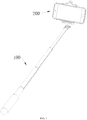
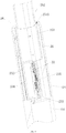
- a selfie stick 100 is provided by an exemplary embodiment of the present disclosure.
- the selfie stick 100 includes a holding bracket 1, a handle 2 and a connecting part 3.
- the holding bracket 1 is operated to hold a photographic device 200.
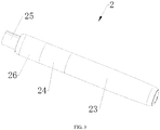
- the handle 2 includes a flexible touch screen 21 and a control module 22.
- the flexible touch screen 21 is operated to detect touch operations.
- the control module 22 is electrically coupled to the flexible touch screen 21.
- the control module 22 is operated to send control signals to the photographic device 200 according to the touch operations.
- the connecting part 3 is connected the holding bracket 1 and the handle 2.
- the connecting part 3 may be of a retractable or foldable structure, such as a pipe assembly or a rod assembly.
- the handle 2 of the selfie stick 100 provides the flexible screen 21 and the control module 22.
- a user may touch the flexible touch screen 21 when holding the handle 2 to take selfies.
- the flexible touch screen 21 is able to detect the touch operations thereon.
- corresponding control signals are transmitted by the control module 22 to the photographic device 200 for control. Since different touch operations may be identified by the flexible touch screen 21, various shooting parameters or functions may be adjusted via different touch operations on the flexible touch screen performed by the user, such as focal length, diaphragm, color, flash.
- the disclosure solves the problem that single button of a selfie stick may just act as a shutter in prior art, but not adjust the shooting parameters in related art is solved. Shooting experience for the users is improved.
- controlling the photographic device 200 to perform different operations may be achieved via different touching operations on the flexible touch screen 21.
- a photographic filter of the photographic device 200 may be switched via a horizontal slide operation.
- Focal length for photographing of the photographic device 200 may be adjusted via vertical slide operations.
- Cameras may be switched between a front camera and a rear camera of the photographic device 200 via a double-click operation.
- the photographic device 200 may take images via a long-press operation.
- the photographic device 200 may be various mobile terminal having photographing functions, such as a mobile phone.
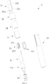
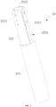
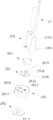
- the handle 2 further includes a handling member 23.
- the handing member 23 includes a holding end 231 and a fixing end 232.
- the fixing end 232 is positioned between the holding end 231 and the connecting part 3.
- the flexible touch screen 21 is positioned around an outer surface 2321 of the fixing end 232. Then the flexible touch screen 21 is positioned between the holding end 231 and the connecting part 3.
- the user may hold the holding end 231 and touch the flexible touch screen 21.
- the position of the flexible touch screen 21 positioned between the holding end 231 and the connecting part 3 fits user usage (including a usage of holding and touching with signal hand in the same time, and a usage of holding in one hand and touching with the other hand). Therefore, it is much more comfortable and convenient for users, improving user experience.
- the flexible touch screen 21 is fixed on the outer surface 2321 of the fixing end 232 via winding.
- the outer surface 2321 of the fixing end 232 is winded by the flexible touch screen 21 in one or less than one circle.
- a side of the flexible touch screen 21 is adhered to the outer surface 2321 of the fixing end 232 via a glue layer.
- the handle 2 includes a touching member 24.
- the touching member 24 is sleeved on the flexible touch screen 21 for protection. Then the touching member 24 is also sleeved on the fixing end 232.
- the touching member 24 is made of transparent and horniness material, such as plastic material.
- the flexible touch screen 21 includes a touching area facing the touching member 24. The flexible touch screen 21 may detect the touching operations performed on the touching area across the touching member 24.
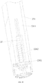
- an interior of the fixing end 232 encloses a first space 2322.
- the fixing end 232 is of a hollow structure, such as a cylinder.
- a slot 2323 runs through the fixing end 232 for communicating the first space 233 with external of the fixing end 232.
- the flexible touch screen 21 extends into the first space 2322 via the slot 2322. Most of the flexible touch screen 21 surrounds the outer surface 2321 of the fixing end 232. An end of the flexible touch screen 21 extends into the first space 2322 via the slot 2323.
- the interior of the holding end 231 further encloses a second space 2311.
- the holding end 231 is of a hollow structure, such as a cylinder.
- the handling member 23 further includes a baffle 233 for separating the first space 2322 and the second space 2311.
- the baffle 233 is positioned between the holding end 231 and the fixing end 232 for separating the first space 2322 from the second space 2311. It is beneficial to utilize inner space of the handling member 23, reduce a volume of the selfie stick 100, and reduce manufacture cost of the selfie stick 100.
- the holding end 231 and the fixing end 232 are integrated in one body to reduce manufacture difficulty and cost.
- the handle 2 further includes a support 234.
- the support 234 is mounted in the first space 2322 for supporting the control module 22.
- the control module 22 is installed on the support 234 and positioned in the first space 2322.
- the flexible touch screen 21 is electrically connected to the control module 22.
- the control module 22 is arranged corresponding to the flexible touch screen 21. It is convenient that the part of the flexible touch screen 21 extending into the first space 2322 connects to the control module 22.
- an inserting hole 2331 is defined in the baffle 233.
- An inserting tab 2341 is positioned at an end of the support 234. The inserting tab 2341 is inserted in the inserting hole 2331 to fix the support 234 on the baffle 233. Then the support 234 and the control module 22 are fixed in the first space 2322. In use of the selfie stick 100, the control module 22 is prevented from damage for shaking. It is beneficial to improve service life of the control module 22.
- control module 22 includes a circuit board 221 and a processing chip 222.
- the circuit board 221 is operated to support the processing chip 222.
- the processing chip 222 is electrically connected with the flexible touch screen 21.
- the processing chip 222 is operated to process touching signals generated by the flexible touch screen 21 in accordance with the touch operations to generate control signals.
- the control module 22 further includes a wireless connector for wirelessly communicating with the photographic device 200.
- the wireless connector is mounted on the circuit board 221.
- the wireless connector is electrically coupled with the processing chip for transmitting the control signals to the photographic device 200.
- Connections such as Bluetooth connectivity, WiFi networking, ZigBee (ZigBee Wireless Networking) connectivity, or NFC (Near Field Communication), are adopted by the wireless connector.
- a mounting hole 2342 is defined in the support 234.
- the circuit board 221 is fixed to the mounting hole 2342 by a first fastener (not illustrated).
- Inner threads are formed on an inner surface of the mounting hole 2342.
- the first fastener may be a screw or a screw bolt.
- the mounting hole 2342 may be formed in an installation post. There may be multiple mounting holes 2342.
- the support 234 may further provides a fixing post 2343 for fixating the circuit board 221, thereby reducing assembly difficulty.
- a limiting board 235 is formed in the first space 2322.
- the limiting board 235 is operated to limit the control module 22.
- the limiting board 235 engages with the support 234 to fix the control module 22.
- the control module 22 may be further prevented from damage for shaking thanks to the limiting board 235.
- the limiting board 235 is connected with the baffle 233 and the fixing end 232.
- the handle 2 further includes a coupling member 25.
- the coupling member 25 includes a first end 251 and a second end 252.
- the first end 251 extends into the first space 2322 to be fixed at the fixing end 232.
- the second end 252 is connected to the connecting part 3.
- a plurality of first fixing holes 2324 is defined in the fixing end 232.
- a plurality of second fixing holes 2511 are defined in the first end 251 and corresponds to the plurality of first fixing holes 2324 one to one. Fixing and positioning for the coupling member 25 and the handling member 23 each other may be achieved, via a fixing member passing through the corresponding first fixing hole 2324 and the second fixing holes 2511.
- the handle 2 further includes a connecting member 26.
- the connecting member 26 is sleeved on outsides of the fixing end 232 for fixing the coupling member 25 to the fixing end 232.
- the first end 251 of the coupling member 25 extends into an interior of the fixing end 232 (also named as first space 2322) firstly.
- the connecting member 26 is sleeved on the outsides of the fixing end 232 for fixing (such as fastening or clamping) the coupling member 25 and the fixing end 232.
- a connection relation between the connecting member 26 and the fixing end 232 may be a threaded connection, clamping connection, or the like.
- the connecting member 26 includes a stop block 261 formed at an end thereof.
- An outer diameter of the first end 251 is greater than that of the second end 252 to form a stepped surface 2510.
- the stepped surface 2510 rests against the stop block 261.
- the stop block 261 of the connecting member 26 rests against the stepped surface 2510 of the coupling member 25 to avoid the coupling member 25 deviating from the handling member 23.
- an outer diameter of the holding end 231 is greater than that of the fixing end 232.
- the touching member 24 is clamped between the connecting member 26 and the holding end 231.
- the connecting member 26 engages with the holding end 231 to position the touching member 24, to avoid a movement of the touching member 24 when the selfie stick 100 in use. Then scratches for the flexible touch screen 24 may be avoided from the touching member 24 to ensure the service life of the selfie stick 100.
- the handle 2 further includes a battery 27.
- the battery 27 is operated to provide power to the control module 22 and the flexible touch screen 21.
- the battery 27 is mounted in the second space 2311.
- the battery 27 and the control module 22 are positioned in two independent spaces, respectively. Negative effects may be avoided from the heat released by the battery 27 to ensure a normal use of the selfie stick 100 and prolong the service life of the selfie stick 100.
- the handle 2 further includes a mounting bracket 236.
- the mounting bracket 236 is fixed in the second space 2311.
- the mounting bracket 236 includes a base board 2361 and a battery housing 2362.
- the battery housing 2362 is positioned on a side of the base board 2361 facing toward the baffle 233.
- the battery 27 is received in the battery housing 2362.
- the battery 27 is fixed by the battery housing 2362 to avoid shakes while using the selfie stick 100.
- a wire hole 2332 is defined in the baffle 233. Electric wires of the battery 27 pass through the wire hole 2332 to connect with the control module 22.
- a through hole 2363 is defined in the base board 2361.
- a fixing post 2312 is formed in the second space 2311 for connecting with the holding end 231.
- a second fastener (not illustrated) passes through the through hole 2363 and extends into the fixing post 2312 to fix the base board 2361 to the holding end 231.
- the fixing post 2312 provides a hole therein, of which a hole wall provides a screw thread.
- the second fastener may be a screw or a bolt.
- the base board 2361 may divide the second space 2311 into a first subspace and a second subspace for optimizing structural arrangement of the internal space of the handle 2.
- the fixing post 2312 is connected to the holding end 231.
- a handle 2 further includes a button module 28.
- the button module 28 is operated to control operative modes of the control module 22, such as state on or state off of power and blue teeth.
- a mounting bracket 236 further includes a protruding post 2364.
- the protruding post 2364 is positioned on a side of the base board 2361 away from the baffle 233.
- the button module 28 is fixed on the protruding post 2364.
- the protruding post 2364 is received in the second space 2311. At least a part of the button module 28 is received in the second space 2311.
- the battery 27 and the button module 28 are positioned in two independent spaces by the base board 2361 respectively. The negative effects of the heat released by the battery 27 may be decreased.
- the button module 28 includes a bottom cover 281.
- a fastening hole 2811 is formed in the bottom cover 281.
- a third fastener (not illustrated) passes through the fastening hole 2811 and extends into the protruding post 2364 to fix the bottom cover 281 to the holding end 231.
- the second space 2311 is closed by the bottom cover 281.
- Foreign impurities may be kept from the second space 2311 by the bottom cover 281.
- a hole is defined in an interior of the protruding post 2364. Threads may be formed on a sidewall of the hole.
- the third fastener is a corresponding screw or screw bolt.
- the button module 28 further includes a button 282, a pressing member 283, and a switch 284.
- the switch 284 is mounted on a side of the base board 2361 facing toward the bottom cover 281.
- the bottom cover 281 includes an inner side 2812 facing toward the mounting bracket 236 and an outer side 2813 away from the mounting bracket 236.
- the pressing member 283 includes a body and an elastic arm 2831.
- the body includes a substrate 2832, a convex plate 2833, and a resisting post 2834.
- the convex plate 2833 and the resisting post 2834 are positioned at opposite sides of the substrate 2832 respectively.
- the elastic arm 2831 is capacity of being elastically deformed.
- the pressing member 283 is mounted on the inner side 2812 by the elastic arm 2831, to enable the body to move relative to the bottom cover 281.
- the convex plate 2833 faces toward the bottom cover 281.
- the resisting post 2834 faces toward the switch 284.
- the button 284 is mounted on the outer side 2813.
- the convex plate 2833 of the pressing member 283 passes through the through hole 2815 of the bottom cover 281 to neighbor with the button 282.
- the button 282 will rest against the convex plate 2833 to move the body toward the switch 284 when pressing the button 282.
- the resisting post 2834 rests against the switch 284 for triggering the switch 284.
- the elastic arm 2831 will enable the body to return its original position when releasing the button 282.
- a fixing hole 2835 is defined in an end of the elastic arm 2831 away from the substrate 2382.
- a positioning post 2814 is positioned on the inner side 2812 of the bottom cover 281. The positioning post 2814 passes through the fixing hole 2835 to fix the bottom cover 281 and the elastic arm 2831.
- a wire groove 2365 is defined in the base board 2361. Electric wires of the switch 284 pass through the wire groove 2365 and the wire hole 2332 to connect with the control module 22.
- the holding bracket 1 includes a bracket body 11 and a motor 12.
- the bracket body 11 is operated to clamp the photographic device 200.
- the motor 12 is operated to move or rotate the bracket body 11 and therefore move or rotate the photographic device 200. Then, camera position and orientation of the photographic device 200 may be controlled.
- the bracket body 11 there are a plurality of light sources (not illustrated) positioned on the bracket body 11.
- the light sources are operated to fill light while the photographic device 200 is shooting.
- a method for controlling a photographic device using a selfie stick is further provided by the exemplary embodiment of the present disclosure.
- the selfie stick 100 described in above embodiments may be applied in the method for controlling the photographic device 200.
- the method for controlling a photographic device using a selfie stick includes:
- various shooting parameters or functions may be adjusted via different operations on the flexible touch screen 21 in the method for controlling the photographic device using the selfie stick, such as focal length, diaphragm, color, and flash, to achieve better shooting experience for users.
- the touch operations may be feedback by a display interface of the photographic device 200 at any time.
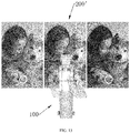
- a photographic filter of the photographic device 200 will be switched when the touch operation is a horizontal slide operation.
- the touch operation is a horizontal slide operation.
- black and white miniature forest, nostalgia, photo processing, fade, years, photo processing.
- a pattern indicated by a label 200' is a view displayed by the photographic device 200.
- the touch operation for the horizontal slide operation is similar to screen switching. It is beneficial to improve user experience.
- a focal length of the photographic device will be adjusted in accordance with the control signals when the touch operation is a vertical slide operation. For example, the focal length is increased with an upward sliding; the focal length is decreased with a downward sliding, or vice versa.
- a pattern indicated by a label 200' is a view displayed by the photographic device 200.
- the touch operation for the vertical sliding operation is appropriate to a pattern displayed by the photographic device 200 for showing the focal length values. It is beneficial to improve using experience for users.
- the photographic device 200 will switch between a front camera and a rear camera in accordance with the control signals when the touch operation is a double-click operation.
- the front camera may be switched to the rear camera, or the rear camera may be switched to the front camera upon double-click operation.
- a pattern indicated by a label 200' is a view displayed by the photographic device 200.
- the photographic device 200 will take a picture in accordance with the control signal when the touch operation is a long-press operation. Since that a long-press operation is applied to correspond with the control signal for shooting, mistake operations caused by mistake touching may be avoided. As illustrated in FIG. 16 , a pattern indicated by a label 200' is a view displayed by the photographic device 200.
- the touching operations include three levels: the first level refers to gestures for activating operation commands; the second level refers to gestures for choosing sub-modes under single mode; the third level refers to gestures for adjusting optimizing degree, parameters of the adjusting mode under the sub modes.
- the photographic device 200 will enter a corresponding main mode when the touch operation is a multi-point touch operation.
- the main mode includes a shooting mode, and/or a filling light mode, and/or a camera adjusting mode, and/or a focal length adjusting mode.
- the multi-point touch includes at least two points tap, such as a double-click operation for entering the shooting mode, a three-point operation for entering the filling light mode, a four-point operation for entering the camera adjusting mode, and a five-point operation for entering the focal length adjusting mode.
- the photographic device 200 will choose a sub-mode subordinated to a chosen main mode according to the control signals when the touch operation is a horizontal slide operation.
- a mode may be chosen from different selfie modes via horizontal slide operations, the different selfie modes including white and black, fade, facial beautification.
- the shooting parameters will be adjusted by the photographic device 200 in the chosen sub-mode according to the control signal when the touch operation is a vertical slide operation.
- facial beautification level from 1 to 9 is adjusted in the beautification mode which is under the shooting mode; contrast ratio of black and white is adjusted in the black and white mode.
- corresponding shooting parameters will be directly adjusted under the main modes by the photographic device 200 in accordance with the control signals when the touch operation is a vertical slide operation or/and horizontal slide operation.
- the sub-mode any more (but enter the sub-mode of the described embodiments above).
- intensity of filling light is adjusted via a swipe-up operation or swipe-down operation, or a left swipe or right swipe.
- left or right angle of the camera is adjusted via a left swipe or right swipe, up or down angle for the camera adjusted via a swipe-up operation or swipe-down operation.
- focal length is adjusted via a swipe-up operation or swipe-down operation.
- no control signal will be generated when the flexible touch screen 21 detecting a single-point sliding operation (such as a single-point horizontal sliding operation or single-point vertical sliding operation). Mistake touching may be avoided during the sliding.
- a single-point sliding operation such as a single-point horizontal sliding operation or single-point vertical sliding operation. Mistake touching may be avoided during the sliding.
- Normal control signals will be generated and sent out when the flexible touch screen 21 detects a double-click sliding operation (such as a double-click horizontal sliding operation or double-click vertical sliding operation). For example, two fingers (usually being a thumb and a forefinger) touch at two positions (like up and down positions) on the flexible touch screen 21 at the same time, respectively. Then the operation is identified as a sliding operation (horizontal movement or vertical sliding).
- a double-click sliding operation such as a double-click horizontal sliding operation or double-click vertical sliding operation.
- the photographic device 200 will take a picture in accordance with the control signals when the touching operation is a single-point operation.
- the touching operation of the single point may be done after adjustments for the photographic device 200, also may be directly done without adjustments for the photographic device 200.
Landscapes
- Engineering & Computer Science (AREA)
- General Engineering & Computer Science (AREA)
- Mechanical Engineering (AREA)
- Multimedia (AREA)
- Signal Processing (AREA)
- Physics & Mathematics (AREA)
- General Physics & Mathematics (AREA)
- Human Computer Interaction (AREA)
- Theoretical Computer Science (AREA)
- Microelectronics & Electronic Packaging (AREA)
- Studio Devices (AREA)
- Accessories Of Cameras (AREA)
- Details Of Cameras Including Film Mechanisms (AREA)
- Camera Bodies And Camera Details Or Accessories (AREA)
Applications Claiming Priority (2)
| Application Number | Priority Date | Filing Date | Title |
|---|---|---|---|
| PCT/CN2016/104714 WO2018082047A1 (fr) | 2016-11-04 | 2016-11-04 | Perche à selfie et procédé de commande de dispositif de photographie au moyen d'une perche à selfie |
| PCT/CN2017/090663 WO2018082322A1 (fr) | 2016-11-04 | 2017-06-28 | Perche à selfie et procédé de commande de dispositif de photographie au moyen d'une perche à selfie |
Publications (1)
| Publication Number | Publication Date |
|---|---|
| EP3537705A1 true EP3537705A1 (fr) | 2019-09-11 |
Family
ID=61600656
Family Applications (2)
| Application Number | Title | Priority Date | Filing Date |
|---|---|---|---|
| EP16920610.9A Withdrawn EP3537702A1 (fr) | 2016-11-04 | 2016-11-04 | Perche à selfie et procédé de commande de dispositif de photographie au moyen d'une perche à selfie |
| EP17868138.3A Withdrawn EP3537705A1 (fr) | 2016-11-04 | 2017-06-28 | Perche à selfie et procédé de commande de dispositif de photographie au moyen d'une perche à selfie |
Family Applications Before (1)
| Application Number | Title | Priority Date | Filing Date |
|---|---|---|---|
| EP16920610.9A Withdrawn EP3537702A1 (fr) | 2016-11-04 | 2016-11-04 | Perche à selfie et procédé de commande de dispositif de photographie au moyen d'une perche à selfie |
Country Status (6)
| Country | Link |
|---|---|
| US (2) | US10986260B2 (fr) |
| EP (2) | EP3537702A1 (fr) |
| JP (1) | JP2020500327A (fr) |
| KR (1) | KR20190069558A (fr) |
| CN (2) | CN107820705A (fr) |
| WO (2) | WO2018082047A1 (fr) |
Cited By (1)
| Publication number | Priority date | Publication date | Assignee | Title |
|---|---|---|---|---|
| EP3883225A4 (fr) * | 2018-11-16 | 2022-01-19 | Winners' Sun Plastic & Electronic (Shenzhen) Co., Ltd. | Perche à selfie et système de commande de photographie et procédé associé |
Families Citing this family (38)
| Publication number | Priority date | Publication date | Assignee | Title |
|---|---|---|---|---|
| US9864257B1 (en) | 2016-09-19 | 2018-01-09 | Gopro, Inc. | Camera frame with side door |
| CN108204494B (zh) * | 2016-12-20 | 2019-07-16 | 深圳市德卡尔科技有限公司 | 手持云台 |
| CN109669600A (zh) * | 2017-10-13 | 2019-04-23 | 华为终端(东莞)有限公司 | 终端亮灭屏的控制方法、装置和终端 |
| USD890835S1 (en) | 2017-12-28 | 2020-07-21 | Gopro, Inc. | Camera |
| CN209557997U (zh) * | 2018-06-27 | 2019-10-29 | 深圳市豪华联合科技有限公司 | 支架及具有其的自拍杆 |
| WO2020033389A1 (fr) | 2018-08-07 | 2020-02-13 | Gopro, Inc. | Caméra et support de caméra |
| USD894256S1 (en) | 2018-08-31 | 2020-08-25 | Gopro, Inc. | Camera mount |
| USD905786S1 (en) | 2018-08-31 | 2020-12-22 | Gopro, Inc. | Camera mount |
| CN112640403A (zh) * | 2018-09-29 | 2021-04-09 | 深圳市柔宇科技股份有限公司 | 握持组件与自拍杆 |
| CN108980589B (zh) * | 2018-10-17 | 2023-10-17 | 歌尔科技有限公司 | 一种头戴显示设备及其移动设备支架 |
| WO2020228015A1 (fr) * | 2019-05-16 | 2020-11-19 | 深圳市柔宇科技有限公司 | Procédé de réponse pour zone tactile de perche pour autoportraits, et terminal mobile |
| CN113330733A (zh) * | 2019-05-31 | 2021-08-31 | 深圳市柔宇科技股份有限公司 | 自拍控制器及其控制方法 |
| US11135473B2 (en) * | 2019-06-19 | 2021-10-05 | Nautilus, Inc. | Media holder for exercise machine |
| USD920419S1 (en) | 2019-09-17 | 2021-05-25 | Gopro, Inc. | Camera |
| CN211525898U (zh) * | 2019-12-19 | 2020-09-18 | 广东百诺影像科技工业有限公司 | 一种带手机夹功能的快装板 |
| USD946074S1 (en) | 2020-08-14 | 2022-03-15 | Gopro, Inc. | Camera |
| CN114726941A (zh) * | 2020-12-22 | 2022-07-08 | 廖茂钧 | 可结合自拍运作的便携式电子装置定位器 |
| USD967238S1 (en) * | 2021-03-17 | 2022-10-18 | Shenzhen Yuansu Chuangda Technology Co., Ltd | Selfie stick clip |
| USD971305S1 (en) * | 2021-04-06 | 2022-11-29 | Shenzhen Jiayz Photo Industrial., Ltd | Stabilizer |
| USD1009121S1 (en) * | 2021-12-09 | 2023-12-26 | Qingxia Xianzi (Shenzhen) Electric Appliance Co., Ltd. | Photo booth |
| JP1729358S (ja) * | 2021-12-10 | 2022-11-08 | 自撮り棒 | |
| US11774833B2 (en) | 2022-02-09 | 2023-10-03 | Nikola Vladimir Bicanic | Methods, systems, apparatuses, and devices for facilitating controlling operation of a content capturing device |
| WO2023154083A1 (fr) * | 2022-02-09 | 2023-08-17 | Nikola Vladimir Bicanic | Procédés, systèmes, appareils et dispositifs pour faciliter la commande du fonctionnement d'un dispositif de capture de contenu |
| USD971989S1 (en) * | 2022-03-25 | 2022-12-06 | Shenzhen Vanplex Co., Ltd | Photo booth |
| USD1107775S1 (en) | 2022-08-04 | 2025-12-30 | Gopro, Inc. | Camera |
| CN115126984A (zh) * | 2022-08-11 | 2022-09-30 | 深圳市艺色科技有限公司 | 潜水手持仪 |
| US12321084B2 (en) | 2022-08-12 | 2025-06-03 | Gopro, Inc. | Interconnect mechanism for image capture device |
| USD1026065S1 (en) * | 2022-12-27 | 2024-05-07 | Linksign Technology Limited | Tablet photo booth |
| US12379650B2 (en) | 2023-02-15 | 2025-08-05 | Gopro, Inc. | Reinforced image capture devices including interconnect mechanisms with a threaded accessory interface |
| USD1039023S1 (en) * | 2023-07-04 | 2024-08-13 | Shenzhen Kingsun Electronics Co. | Photo booth |
| USD1040211S1 (en) * | 2023-08-01 | 2024-08-27 | Shenzhen Kingsun Electronics Co. | Photo booth |
| USD1096914S1 (en) | 2024-03-15 | 2025-10-07 | Gopro, Inc. | Camera mount |
| USD1100025S1 (en) | 2024-03-15 | 2025-10-28 | Gopro, Inc. | Camera mount |
| US12574622B2 (en) | 2024-03-15 | 2026-03-10 | Gopro, Inc. | Image capture apparatus including a multi-function interconnect mechanism |
| USD1057801S1 (en) * | 2024-05-17 | 2025-01-14 | Shenzhen VIVIDTOK Technology Co., Ltd | 360° photo booth |
| USD1118735S1 (en) | 2024-05-22 | 2026-03-17 | Gopro, Inc. | Camera |
| USD1057808S1 (en) * | 2024-06-26 | 2025-01-14 | Shenzhen Aike Global Industrial Co., Ltd. | Photography stick |
| US20260029695A1 (en) * | 2024-07-24 | 2026-01-29 | Kathryn G. O'Hare | Apparatus for Photographing Animals |
Family Cites Families (17)
| Publication number | Priority date | Publication date | Assignee | Title |
|---|---|---|---|---|
| US9310836B2 (en) * | 2013-05-02 | 2016-04-12 | Amazon Technologies, Inc. | Resin-encapsulated portable media device |
| US9367094B2 (en) * | 2013-12-17 | 2016-06-14 | Apple Inc. | Display module and system applications |
| US9979878B2 (en) * | 2014-02-21 | 2018-05-22 | Light Labs Inc. | Intuitive camera user interface methods and apparatus |
| CN204119349U (zh) * | 2014-09-11 | 2015-01-21 | 源德盛塑胶电子(深圳)有限公司 | 一种一体式自拍装置 |
| CN204227000U (zh) * | 2014-11-10 | 2015-03-25 | 李强 | 自拍杆 |
| CN204403741U (zh) * | 2015-01-08 | 2015-06-17 | 海宁市丰达电子有限公司 | 一种自拍杆 |
| TWI582519B (zh) * | 2015-04-30 | 2017-05-11 | 鴻海精密工業股份有限公司 | 自拍裝置 |
| CN204795224U (zh) * | 2015-05-28 | 2015-11-18 | 宇龙计算机通信科技(深圳)有限公司 | 一种自拍杆 |
| KR101667394B1 (ko) * | 2015-08-25 | 2016-10-19 | (주) 에셀티 | 파지 및 착용 가능한 휴대용 단말기 흔들림 보정장치 |
| CN204948164U (zh) * | 2015-09-02 | 2016-01-06 | 深圳市信毅科技有限公司 | 一种自拍伸缩杆和自拍杆装置 |
| CN105137701A (zh) * | 2015-09-08 | 2015-12-09 | 小米科技有限责任公司 | 自拍杆及拍照方法 |
| CN105472254B (zh) * | 2015-12-29 | 2018-04-06 | 广东欧珀移动通信有限公司 | 一种对焦方法和装置、自拍杆、移动终端及自拍系统 |
| CN105650416B (zh) * | 2015-12-29 | 2018-05-25 | 广东欧珀移动通信有限公司 | 一种自拍杆旋转方法和装置及自拍杆 |
| CN105472225A (zh) * | 2016-01-14 | 2016-04-06 | 福州觉感视觉软件科技有限公司 | 一种可更换模组的智能相机 |
| CN205490870U (zh) * | 2016-03-18 | 2016-08-17 | 广东欧珀移动通信有限公司 | 自拍系统和自拍杆 |
| CN105975830B (zh) * | 2016-05-03 | 2019-04-09 | Oppo广东移动通信有限公司 | 一种智能控制自拍杆的方法、装置及自拍杆 |
| CN105933487A (zh) * | 2016-07-15 | 2016-09-07 | 江沛阳 | 一种智能自拍杆 |
-
2016
- 2016-11-04 EP EP16920610.9A patent/EP3537702A1/fr not_active Withdrawn
- 2016-11-04 KR KR1020197015040A patent/KR20190069558A/ko not_active Ceased
- 2016-11-04 CN CN201680036289.XA patent/CN107820705A/zh active Pending
- 2016-11-04 JP JP2019522270A patent/JP2020500327A/ja active Pending
- 2016-11-04 US US16/347,695 patent/US10986260B2/en not_active Expired - Fee Related
- 2016-11-04 WO PCT/CN2016/104714 patent/WO2018082047A1/fr not_active Ceased
-
2017
- 2017-06-28 CN CN201780004307.0A patent/CN108370418B/zh not_active Expired - Fee Related
- 2017-06-28 WO PCT/CN2017/090663 patent/WO2018082322A1/fr not_active Ceased
- 2017-06-28 US US16/466,844 patent/US20190327407A1/en not_active Abandoned
- 2017-06-28 EP EP17868138.3A patent/EP3537705A1/fr not_active Withdrawn
Cited By (1)
| Publication number | Priority date | Publication date | Assignee | Title |
|---|---|---|---|---|
| EP3883225A4 (fr) * | 2018-11-16 | 2022-01-19 | Winners' Sun Plastic & Electronic (Shenzhen) Co., Ltd. | Perche à selfie et système de commande de photographie et procédé associé |
Also Published As
| Publication number | Publication date |
|---|---|
| CN108370418A (zh) | 2018-08-03 |
| WO2018082047A1 (fr) | 2018-05-11 |
| US20190258142A1 (en) | 2019-08-22 |
| US20190327407A1 (en) | 2019-10-24 |
| JP2020500327A (ja) | 2020-01-09 |
| CN107820705A (zh) | 2018-03-20 |
| KR20190069558A (ko) | 2019-06-19 |
| US10986260B2 (en) | 2021-04-20 |
| WO2018082322A1 (fr) | 2018-05-11 |
| CN108370418B (zh) | 2021-03-23 |
| EP3537702A1 (fr) | 2019-09-11 |
Similar Documents
| Publication | Publication Date | Title |
|---|---|---|
| EP3537705A1 (fr) | Perche à selfie et procédé de commande de dispositif de photographie au moyen d'une perche à selfie | |
| US10533714B2 (en) | External lighting cases for mobile digital camera devices | |
| US20180367183A1 (en) | Protective case for mobile device with displaced camera control | |
| JP6838066B2 (ja) | Lcd表示モジュール及び移動端末 | |
| US8214568B2 (en) | Device, system, and method to couple a personal digital assistant with a camera | |
| US9075572B2 (en) | Media enhancement dock | |
| CN204928927U (zh) | 全显示屏手机 | |
| CN207835535U (zh) | 一种带红外对射的智能控制无线充支架 | |
| BR102014016654B1 (pt) | Sistema de dispositivo móvel com câmera removível e seu método de utilização | |
| EP3225903B1 (fr) | Ampoule électrique à projection intelligente et son procédé de projection interactive et intelligente | |
| CN206682735U (zh) | 光感指示装置及电子设备 | |
| CN206237502U (zh) | 防水型全景相机 | |
| JP3228394U (ja) | モバイル電子機器用の防水ケース | |
| CN206790539U (zh) | 一种功能配件分离式智能手机 | |
| CN104254220A (zh) | 便携式电子装置 | |
| KR20150136384A (ko) | 카메라 제어 기능을 갖는 모바일 단말용 케이스 | |
| EP3574632B1 (fr) | Combinaison de capteurs | |
| JP2016145949A (ja) | フラッシュモジュール及びこれを用いた写真撮影システム | |
| KR101424392B1 (ko) | 모바일 단말기용 셔터 | |
| CN104345315B (zh) | 测量系统及其使用方法 | |
| CN107968859A (zh) | 输出模组和电子装置 | |
| CN109962995B (zh) | 功能组件、电子装置及其控制方法 | |
| CN112702585A (zh) | 图像投影装置 | |
| US20250328172A1 (en) | Handheld bluetooth photographing screen | |
| CN210579186U (zh) | 一种电子设备 |
Legal Events
| Date | Code | Title | Description |
|---|---|---|---|
| PUAI | Public reference made under article 153(3) epc to a published international application that has entered the european phase |
Free format text: ORIGINAL CODE: 0009012 |
|
| 17P | Request for examination filed |
Effective date: 20190530 |
|
| AK | Designated contracting states |
Kind code of ref document: A1 Designated state(s): AL AT BE BG CH CY CZ DE DK EE ES FI FR GB GR HR HU IE IS IT LI LT LU LV MC MK MT NL NO PL PT RO RS SE SI SK SM TR |
|
| AX | Request for extension of the european patent |
Extension state: BA ME |
|
| DAV | Request for validation of the european patent (deleted) | ||
| DAX | Request for extension of the european patent (deleted) | ||
| STAA | Information on the status of an ep patent application or granted ep patent |
Free format text: STATUS: THE APPLICATION HAS BEEN WITHDRAWN |
|
| 18W | Application withdrawn |
Effective date: 20200416 |