EP3537723B1 - Automatisierte erfassung von informationen über eine feste verkabelung - Google Patents
Automatisierte erfassung von informationen über eine feste verkabelung Download PDFInfo
- Publication number
- EP3537723B1 EP3537723B1 EP19161100.3A EP19161100A EP3537723B1 EP 3537723 B1 EP3537723 B1 EP 3537723B1 EP 19161100 A EP19161100 A EP 19161100A EP 3537723 B1 EP3537723 B1 EP 3537723B1
- Authority
- EP
- European Patent Office
- Prior art keywords
- equipment
- information
- port
- cable
- patching equipment
- Prior art date
- Legal status (The legal status is an assumption and is not a legal conclusion. Google has not performed a legal analysis and makes no representation as to the accuracy of the status listed.)
- Not-in-force
Links
Images



Classifications
-
- H—ELECTRICITY
- H01—ELECTRIC ELEMENTS
- H01R—ELECTRICALLY-CONDUCTIVE CONNECTIONS; STRUCTURAL ASSOCIATIONS OF A PLURALITY OF MUTUALLY-INSULATED ELECTRICAL CONNECTING ELEMENTS; COUPLING DEVICES; CURRENT COLLECTORS
- H01R13/00—Details of coupling devices of the kinds covered by groups H01R12/70 or H01R24/00 - H01R33/00
- H01R13/66—Structural association with built-in electrical component
- H01R13/70—Structural association with built-in electrical component with built-in switch
- H01R13/703—Structural association with built-in electrical component with built-in switch operated by engagement or disengagement of coupling parts, e.g. dual-continuity coupling part
-
- G—PHYSICS
- G01—MEASURING; TESTING
- G01R—MEASURING ELECTRIC VARIABLES; MEASURING MAGNETIC VARIABLES
- G01R31/00—Arrangements for testing electric properties; Arrangements for locating electric faults; Arrangements for electrical testing characterised by what is being tested not provided for elsewhere
- G01R31/50—Testing of electric apparatus, lines, cables or components for short-circuits, continuity, leakage current or incorrect line connections
- G01R31/66—Testing of connections, e.g. of plugs or non-disconnectable joints
- G01R31/70—Testing of connections between components and printed circuit boards
-
- H—ELECTRICITY
- H04—ELECTRIC COMMUNICATION TECHNIQUE
- H04Q—SELECTING
- H04Q1/00—Details of selecting apparatus or arrangements
- H04Q1/02—Constructional details
- H04Q1/13—Patch panels for monitoring, interconnecting or testing circuits, e.g. patch bay, patch field or jack field; Patching modules
Definitions
- Automated infrastructure management (AIM) systems are typically used to automatically detect and document changes in patching connections made in a structured cabling system.
- patching connections are typically made by connecting two or more connections points (also referred to here as a "ports") located on the front side of patching equipment. These patching connections are made using patch cords that are connected to the ports.
- each port on the front of an item of patching equipment is connected by the patching equipment to a cable that is terminated at the rear of the patching equipment. Changes to such rear cables typically occur infrequently (for example, when the patching equipment is first installed or during building remodeling).
- This cabling is also referred to here as “fixed cabling,” and the associated connections are also referred to here as “fixed connections.”
- AIM systems have not historically been configured to automatically detect and document changes to the fixed cabling. As a result, information about the fixed cabling and associated connections have historically been manually captured and supplied to any AIM database.
- information about fixed cabling and connections is captured when the cables are installed.
- technicians installing such fixed cables and connections can manually capture information about the fixed cables and connections using various devices (for example, cable testers) and manually enter the captured information into a spreadsheet using a portable computer. Later, the spreadsheet can be imported into a database.
- this manual work flow can be inconvenient for the technicians and prone to errors.
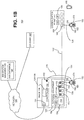
- FIG. 1A is a block diagram of one exemplary embodiment of an automated infrastructure management (AIM) system 100 that is configured to track connections made using items of patching equipment 102.
- the connections can be made with various types of cabling, including, without limitation, copper cables and fiber optic cables.
- the system 100 shown in FIG. 1A can be implemented in a data center or enterprise application. Other embodiments can be implemented in other ways (for example, where the system 100 is implemented in a central office or other facility of a telecommunication service provider and/or in another part of the telecommunication service provider's network).
- the patching equipment 102 is deployed in racks along with other items of equipment (not shown) (such as servers, routers, and switches).
- the AIM system 100 is configured to track connections made at the patching equipment 102 as well as connections with the other equipment.
- the AIM system 100 is configured to work with patching equipment 102 (such as patch panels) that has AIM functionality 104 for tracking connections made at the ports 106 located on the front (or patching) side of the patching equipment 102.
- patching equipment 102 is also referred to here as "intelligent patching equipment" 102.
- the patching equipment 102 is shown as having four ports 106; however, it is to be understood that this is for the purposes of illustration and that the patching equipment 102 can include a different number of ports 106.
- the AIM functionality 104 comprises a sensor, reader, interface, or other circuitry (collectively referred to here as a "sensor") 108 for use in determining the presence of, and/or information from or about, a connector and/or cable attached to the associated port 106.
- the AIM functionality 104 further comprises one or more visual indicators 110 (such as one or more light emitting diodes (LEDs)) for providing a visual indication to a user, for example, to enable the user to visually identify that particular port 106.
- the AIM functionality 104 also comprises a respective user-input device 112 (such as a button) by which a user is able to select that port 106.
- the AIM functionality 104 can be implemented in many different ways and the particular configuration illustrated in FIG. 1A is merely exemplary and should not be construed as limiting.
- Each sensor 108, visual indicator 110, or user-input device 112 can be associated with a single port 106 or can be associated with multiple ports 106 (for example, these items can be associated with all of the ports 106 or with a subset of ports 106 such as a row or other grouping of ports 106).
- AIM technology can be used.
- One type of AIM technology infers connection information by sensing when connectors are inserted or removed from ports.
- Another type of AIM technology makes use of so-called “ninth wire” or “tenth wire” technology.
- Ninth wire/tenth wire technology makes use of special cables that include one or more extra conductors or signal paths that are used for determining which port each end of the cable is inserted into.
- Yet another type of AIM technology makes use of an Electrically Erasable Programmable Read-Only Memory (EEPROM) or other storage device that is integrated with or attached to a connector on a cable. The storage device is used to store an identifier for the cable or connector along with other information.
- EEPROM Electrically Erasable Programmable Read-Only Memory
- the port (or other connector) into which the associated connector is inserted is configured to read the information stored in the EEPROM when the connector is inserted into the front side of a port of a patch panel or other item of patching equipment.
- a similar approach can be used with optical machine-readable representations of data (such as barcodes or QR codes).
- RFID radio frequency identification
- each item of intelligent patching equipment 102 includes a respective programmable processor 114 that is communicatively coupled to the other AIM functionality 104 in that item of patching equipment 102.
- the programmable processor 114 is configured to execute software that reads or otherwise receives information from each sensor 108, controls the state of each visual indicator 110, and determines the state of each button 112.
- the sensor 108, visual indicator 110, button 112, and processor 114 can be natively integrated into the patching equipment 102 or can be packaged into a retrofit kit that can be installed on already deployed patching equipment 102.
- the AIM system 100 further comprises one or more controllers 116.
- the controller 116 is implemented as a unit that is separate from the patching equipment 102 such that one controller 116 is able to serve multiple items of patching equipment 102. It is to be understood, however, that other embodiments can be implemented in other ways.
- one or more items of patching equipment 102 can have a controller 116 integrated within the patching equipment 102 so that the controller 116 is a part of the patching equipment 102 instead of being separate therefrom.
- each controller 116 is configured to be connected to, and manage, patching equipment 102 having AIM functionality 104 that is installed in one or more racks 118 and is also referred here as a "rack controller 116.”
- Each rack controller 116 aggregates connection information for the ports 106 of the patching equipment 102 in the associated racks 118. More specifically, each rack controller 116 is configured to use the sensor 108 associated with each port 106 of the patching equipment 102 mounted in the associated rack 118 to monitor the state of each port 106 and identify connection or disconnection events occurring at that port 106 (for example, by detecting changes in the connection state of the port 106). Also, each rack controller 116 is configured to illuminate or otherwise actuate any visual indicators 110 associated with the port 106 and to monitor the state of each button 112 associated with that port 106 and identify any events occurring at such buttons 112 (for example, button press and/or release events).
- each rack controller 116 comprises at least one programmable processor 120 on which software or firmware 122 executes.
- the software 122 comprises program instructions that are stored (or otherwise embodied) on an appropriate non-transitory storage medium or media 124 from which at least a portion of the program instructions are read by the programmable processor 120 for execution thereby.
- the software 122 is configured to cause the processor 120 to carry out at least some of the operations described here as being performed by that controller 116.
- the storage medium 124 is shown in FIG.
- each rack controller 116 also comprises memory 126 for storing the program instructions and any related data during execution of the software 122.
- Each rack controller 116 also includes a display device 128 for displaying information for a user located at the associated rack 118 and a user-input device 130 for receiving user-input from such a user.
- the display device 128 and the user-input device 130 are implemented together in a liquid crystal display (LCD) touch screen that is used for both displaying information and receiving user input.
- LCD liquid crystal display
- Each rack controller 116 includes a power supply 132 that is configured to provide power for rack controller 116 and the patching equipment 102 connected to the rack controller 116.
- the power supply 132 is implemented separately from the controller 116.
- each rack controller 116 comprises an external network interface 134 that can be used to directly connect that rack controller 116 to an external network 136 (shown in FIG. 1A ).
- the external network 136 is implemented as an ETHERNET LAN and, as a result, the external network interface 134 comprises an ETHERNET interface and is also referred to here as "ETHERNET interface" 134.
- each rack controller 116 provides asset and connection information to an AIM system manager 138.
- the AIM system manager 138 is configured to compile asset and connection information and to provide an end-to-end trace of connections.
- the AIM system manager 138 stores the asset and connection information in an AIM database 140.
- the AIM system manager 138 and AIM database 140 can be implemented using one or more computers on which appropriate software is executed.
- fixed cables 142 are connected to the rear of the patching equipment 102 (for example, using punch-down blocks).
- the patching equipment 102 is configured so that each port 106 on the front of the patching equipment 102 is connected to at least one fixed cable 142 in order to establish a communication path between that port 106 and the at least one fixed cable 142.
- each fixed cable 142 is terminated at another item of equipment (referred to here generally as "other equipment” 144).
- the other equipment 144 comprises a wall outlet that is deployed in the worked area.
- the other end of the fixed cabling 142 can be coupled to other types of equipment. That is, the "other equipment" 144 referred to here can comprise other types of equipment.
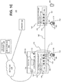
- the other equipment 144 can comprise a consolidation point 144 or, as shown in FIG. 1C , the other equipment 144 can comprises another item of patching equipment (referenced in this context with reference numeral 144).
- FIGS. 1A-1C only a single fixed cable 142 and item of other equipment 144 is shown in FIGS. 1A-1C ; however, it is to be understood that multiple fixed cables 142 and items of other equipment 144 (and multiple types of other equipment 144) can and typically would be used.
- Each item of other equipment 144 typically includes one or more ports 146.
- the wall outlet 144 includes one or more ports 146 on the front of the outlet 144.
- the outlet 144 is shown as having one port 146; however, it is to be understood that this is for the ease of illustration and that the outlet 144 can include a different number of ports 146.
- each outlet 144 can also comprise a faceplate 147 to which the ports 146 are mounted.
- the outlets 144 can be implemented in other ways.
- the consolidation point 144 includes multiple ports 146 where respective fixed cables 142 can be terminated at the rear of the ports 146 and other cables can be connected to the front of the ports 146, where each of those other cables can be terminated at its other end in the work area (for example, at a wall outlet).
- that other item of patching equipment (referenced in this context with reference numeral 144) is implemented as described above and also includes multiple ports (referenced in this context with reference numeral 146) where the relevant fixed cable 142 can be terminated at the rear of one of the ports 146 and other cables can be connected to the front of that port 146.
- the patching equipment 102 does not include any sensors to automatically detect when a cable is connected to the rear (non-patching side) of the patching equipment 102. For example, there is no sensor to automatically detect when a fixed cable 142 has been connected to the rear of an item of patching equipment 102.
- Each connection between a port 106 of patching equipment and a port 146 of the other item of equipment 144 (which includes the fixed cable 142) is tested by two technicians using a respective cable tester 152.
- One technician is located near the patching equipment 102, and the second technician is located near the item of other equipment 144.
- the technicians use the cable testers 152 to verify the transmission performance requirements for the connection (for example, by verifying that the requirements specified in TIA/EIA TSB-67 are met).
- the technicians also verify that each such connection has been correctly established and labeled at the specified port 106 of the patching equipment 102 and at the specified port 146 of the item of other equipment 144.
- Each cable tester 152 is configured so that one end of a probe cable 154 can be attached to a probe port 156 of the cable tester 152.
- the other end of the probe cable 154 can be connected to a port 106 of the patching equipment 102.
- the other end of the probe cable 154 can be connected to a port 146 of that other equipment 144.
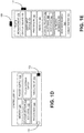
- Each cable testers 152 also comprises at least one programmable processor 158 on which software or firmware 160 executes.
- the software 160 comprises program instructions that are stored (or otherwise embodied) on an appropriate non-transitory storage medium or media 162 from which at least a portion of the program instructions are read by the programmable processor 158 for execution thereby.
- the software 160 is configured to cause the processor 158 to carry out at least some of the operations described here as being performed by that cable tester 152.
- each storage medium 162 is shown in FIG. IE as being included in the cable tester 152, it is to be understood that remote storage media (for example, storage media that is accessible over a network) and/or removable media can also be used.
- each cable tester 152 also comprises memory 164 for storing the program instructions and any related data during execution of the software 160.
- each cable tester 152 also includes a display device 166 for displaying information for a user and a user-input device 168 for receiving user input from such a user.
- each display device 166 is implemented using a LCD display
- each user-input device 68 is implemented using a keypad.
- the display device 166 and the user-input device 168 for each cable tester 152 are implemented together in a liquid crystal display (LCD) touch screen that is used for both displaying information and receiving user input.
- LCD liquid crystal display
- Each cable tester 152 also includes test and measurement circuitry 170 that is configured to (under the control of the programmable processor 158 and software 160 executing thereon) transmit and receive testing and measurement signals over the probe cable 154.
- the test and measurement circuitry 170 and programmable processor 158 (and software 160 executing thereon) are configured to test, measure, and/or otherwise determine the following about the associated connection: connectivity, length, attenuation, wire map, near-end crosstalk (NEXT), impedance, capacitance, resistance, delay, delay skew, equal level far-end crosstalk (ELFEXT), and attenuation-to-crosstalk ratio (ACR).
- test and measurement circuitry 170 and programmable processor 158 can be configured to test, measure, and/or otherwise determine the following about the associated connection: fiber type, insertion loss, measured loss at 850 nanometers (nm), limit loss at 850 nm, margin loss at 850 nm, measured loss at 1300 nm, limit loss at 1300 nm, and margin loss at 1300 nm.
- the test and measurement circuitry 170 is configured in other ways.
- any data that would be captured during such cable tester verification processes would be manually captured (for example, in spreadsheet file) and manually entered or imported into an AIM database 140 at a later point in time.
- this work flow can be error prone and inconvenient for the technicians.
- the rack controller 116 is configured to automatically retrieve data that is collected by a cable tester 152 and to automatically associate such data with the appropriate ports 106 and 146 and patching equipment 102 and other equipment 144. Also, the rack controller 116 is configured to locally store data collected by a cable tester 152 and data indicating which ports 106 and 146 and patching equipment 102 and other equipment 144 are associated with. This data can be retrieved by the AIM system manager 138 and used to create and/or populate appropriate objects in the AIM database 140.
- a cable tester 152 is communicatively coupled to the rack controller 116. This can be done using a wired connection.
- the rack controller 116 includes a Universal Serial Bus (USB) interface 172
- the cable tester 152 includes a USB interface 174.
- USB Universal Serial Bus
- a wired connection can be established between the rack controller 116 and the cable tester 152 by attaching one end of USB cable 176 to the USB interface 172 of the rack controller 116 and the other end of the USB cable 176 to the USB interface 174 of the cable tester 152.
- the cable tester 152 can be communicatively coupled to the rack controller 116 using a wireless connection.
- the rack controller 116 includes a wireless interface 178
- the cable tester 152 includes a wireless interface 180.
- a wireless connection can be established between the rack controller 116 and the cable tester 152 using the wireless interfaces 178 and 180.
- This can be done using a wireless local area network, in which case the wireless interfaces 178 and 180 are configured to implement the appropriate wireless local area network interfaces and protocols (for example, one or more of the Institute of Electrical and Electronics Engineers (IEEE) 802.11 family of wireless local area network protocols).
- IEEE Institute of Electrical and Electronics Engineers
- This can be done using a different wireless protocol (for example, by using one or more of the BLUETOOTH family of wireless protocols).
- the software 160 executing on the cable tester 152 implements an interface 182 (shown in FIG. IE) that the software 122 executing on the rack controller 116 is able to use to request that the cable tester 152 provide information to the rack controller 116.
- This information can include information that the cable tester 152 has received, measured, or otherwise obtained.
- the interface 182 implemented in the software 160 executing on the cable tester 152 provides the requested information to the rack controller 116 over the connection that is established between the cable tester 152 and the rack controller 116.
- the patching equipment 102 and the other equipment 144 include storage devices 184 in which information can be stored locally.
- Each such storage device 184 includes, or is coupled to, an associated wireless interface 186 by which information can be written to the associated storage device 184 and by which information stored in the associated storage device 184 can be read.
- a portable device for example, a cable tester 152 or a smartphone or tablet 188, near the patching equipment 102 or other equipment 144 can be used to read and write data from and to the storage device 184 using the wireless interface 186.
- An item of patching equipment 102 or other equipment 144 can include a single storage device 184 and wireless interface 186 regardless of the number of ports 106 or 146 included in the patching equipment 102 or other equipment 144. Also, an item of patching equipment 102 or other equipment 144 can include multiple storage devices 184 - for example, where a separate storage device 184 is provided for each port 106 or 146 or where a separate storage device 184 is provided for each subset (such as a row or other grouping) of ports 106 or 146.
- an item of patching equipment 102 or other equipment 144 can include multiple wireless interface 186 - for example, where a separate wireless interface 186 is provided for each storage device 184 or where a separate storage device 184 is provided for each subset of storage devices 184.
- information related to the fixed cable 142 coupled to each port 106 and port 146 can be written to the associated storage device 184 during installation or when any changes are made to the cable 142. Thereafter, information about that cabling 142 can be read using a portable device (such as a smartphone or tablet 188). Other data can be written to and read from the storage devices 184.
- Each storage device 184 and wireless interface 186 can be implemented using near-field communication (NFC) technology.
- NFC near-field communication
- power for each storage device 184 and wireless interface 186 can be provided by the portable device using the NFC technology.
- data can be written to and read from each storage device 184 even if power is not otherwise being provided to the patching equipment 102 or the other equipment 144.
- Wall outlets and consolidation points are typically passive devices and are not otherwise powered.
- the patching equipment 102 shown in FIGS. 1A-1C is typically provided power (for example, from the rack controller 116 or a power supply installed with the rack controller 116), there are situations where power is not being provided to the patching equipment 102. This can occur, for example, during the initial installation of the AIM system 100 or during major changes to the AIM system 100. In these situations, a technician using a cable tester 152 or other portable device is still able to write information to and read information from the storage devices 184.
- information about the installed connection and fixed cabling can be locally stored in storage device 184 associated with, and local to, the relevant ports and thereafter, at an appropriate and convenient time, read by a portable device (such as a smartphone or table 188) that is near one of the relevant ports.
- a portable device such as a smartphone or table 1878 that is near one of the relevant ports.
- This can be done to obtain information about the port and the associated connection and fixed cabling without having to access the AIM system 138 and AIM database 140.
- This is useful in situations where the AIM system 138 has not been configured and/or where the AIM database 140 has not been created or populated. This is also useful in situations where the AIM system 138 and the AIM database 140 are not available or accessible.
- each storage device 184 and wireless interface 186 can be implemented so as to be powered using at least one of a battery, a solar cell, or mains or grid power.
- each storage device 184 and wireless interface 186 in some of the patching equipment 102 or other equipment 144 can be configured to transmit a beacon that includes at least some of the information stored in the storage device 184.
- each storage device 184 and wireless interface 186 can be configured to join a mesh network (including, for example, other similarly configured patching equipment 102 or other equipment 144 and a gateway 187 connected to an external network 136) to enable a remote external device to write information to and read information from the storage device 184 using the wireless interface 186.
- the AIM manager 138 can access information stored in the storage device 184 via the gateway 187 and the mesh network.
- a suitable mesh networking protocol can be used (for example, BLUETOOTH LOW ENERGY).
- FIG. 2 comprises a high-level flow chart illustrating one exemplary embodiment of a method 200 of automatically capturing information about fixed cabling.
- the embodiment of method 200 shown in FIG. 2 is described here as being implemented using the AIM system 100 of FIG. 1A , though it is to be understood that other embodiments can be implemented in other ways.
- the blocks of the flow diagram shown in FIG. 2 have been arranged in a generally sequential manner for ease of explanation; however, it is to be understood that this arrangement is merely exemplary, and it should be recognized that the processing associated with method 200 (and the blocks shown in FIG. 2 ) can occur in a different order (for example, where at least some of the processing associated with the blocks is performed in parallel and/or in an event-driven manner). Also, most standard exception handling is not described for ease of explanation; however, it is to be understood that method 200 can and typically would include such exception handling.
- Method 200 comprises communicatively coupling a cable tester 152 to the controller 116 (block 202). This can be done by establishing a wired or wireless connection between a cable tester 152 and the controller 116.
- the controller 116 will automatically discover that a cable tester 152 has been communicatively coupled to it and, in response, enter a special mode (referred to here as "cable tester mode") in which the controller 116 interacts with the cable tester 152.
- a cable tester 152 has been communicatively coupled to it and, in response, enter a special mode (referred to here as "cable tester mode") in which the controller 116 interacts with the cable tester 152.
- the technician using the cable tester 152 interacts with the display device 128 and user-input device 130 of the controller 116 in order to inform the rack controller software 122 that the cable tester 152 has been coupled to it and to place the controller 116 into cable tester mode.
- the controller software 122 can be configured to display a message on the display devices 128 of the controller 116 indicating that the rack controller 116 is in cable tester mode.
- Method 200 further comprises detecting, by the controller 116 while operating in the cable tester mode, the connection of a cable to a port 106 of an item of patching equipment 102 that is within the domain of the controller 116 (block 204).
- each item of patching equipment 102 includes AIM functionality 104 that comprises sensors 108 for detecting if a cable is connected the connection and disconnection of cables to and from ports 106 of patching equipment 102 within the domain of the controller 116.
- connection event can be considered to have occurred when a port 106 that was previously in an "empty" or “disconnected” state (that is, a state in which no cable is connected to the associated port 106) changes to a "connected” state (that is, a state in which a cable is connected to the associated port 106).
- a disconnection event can be considered to have occurred when a port 106 that was previously in the connected state changes to the disconnected state.
- the particular port 106 and associated item of patching equipment 102 where the controller 116 has determined that the detected connection event occurred are referred to here as the "identified port 106" and the "identified patching equipment 102.”
- connection between an item of patching equipment 102 and other equipment 144 (such as a wall outlet, consolidation point, or other item of patching equipment).
- the connection includes a fixed cable 142.
- the connection is terminated at the rear (or non-patching) side of the patching equipment 102 and at the rear of the other equipment 144 and is coupled, by the patching equipment 102 and the other equipment 144, respectively, to the port 106 and 146 on the front (or patching) side.
- the technicians use cable testers 152 to test and verify the installed connection.
- the rack controller 116 is configured to assume that, while operating in cable tester mode, any detected connection event is the result of a technician connecting a probe cable 154 to the identified port 106, where the other end of the probe cable 154 is tethered to a cable tester 152 being used by that technician.
- the cable testers 152 are configured to receive identification and/or location information associated with the connection (and associated fixed cabling) that is being tested.
- this identification information can include identifiers assigned to the cabling (referred to here as “cable identifiers” or “cable IDs”), to the ports 106 and 146 of the patching equipment 102 and other equipment 144 (also referred to here as “port identifiers” or “port IDs”), the patching equipment 102 and other equipment 144 themselves (also referred to here “patching equipment identifiers” or “patching equipment IDs” and “outlet identifiers” or “outlet IDs”, respectively).
- This identification information can also include an identifier assigned to a bundle of cables used for providing Power-Over-Ethernet (POE) service to devices (also referred to here as a "bundle identifier" or “bundle ID”).
- identifier assigned to a bundle of cables used for providing Power-Over-Ethernet (POE) service to devices also referred to here as a "bundle identifier" or “bundle ID”
- Standards and specifications such as those promulgated by the Telecommunications Industry Associations (TIA), include guidance regarding providing POE service over a bundle of cables (including recommendations regarding the maximum temperature rise).
- the location information can include a building, floor, room, row, rack, or indoor coordinates where any of the following are located: a port 106, an item of patching equipment 102, an end of a cable, or an end of a connection implemented using a cable.
- the location information for a port 106, cable, or connection can also include a name, identifier, or other information associated with any of the following: a second port to which the port 106, cable, or connection is also connected and the equipment (such as an item of patching equipment, outlet, or other equipment such as a server, switch, or router) of which the second port is a part.
- the software 160 executing on the cable tester 152 can be configured to prompt the technician to enter such information (for example, by displaying a message on the display device 166 of the cable tester 152). In response, the technician enters the information (for example, using the user input device 168 of the cable tester 152) and the software 160 executing on the cable tester 152 is configured to receive and store the entered information.
- identifier information to be downloaded to the cable tester 152 can be entered using a computer, and then the entered information can be downloaded to the cable tester 152 (for example, over a wired or wireless connection established with the cable tester 152).
- the cable tester 152 can receive such information is by scanning a bar or QR code or reading an RFID tag that encodes or stores identification and/or location information for an item (such as a cable, connector, port, item of patching equipment, shelf, rack, row, room, floor, building, etc.) to which it is attached or in which it is located.
- the cable tester 152 includes an appropriate optical scanner or RFID reader 181 (shown in FIG. IE) and software therefor.
- the cable testers 152 can receive the identifier information before or after the probe cable 154 is connected to the identified port 106.
- testing information can include information about one or more of the following about the fixed cabling being tested: connectivity, length, attenuation, wire map, near-end crosstalk (NEXT), impedance, capacitance, resistance, delay, delay skew, equal level far-end crosstalk (ELFEXT), and attenuation-to-crosstalk ratio (ACR).
- this testing information can include information about one or more of the following about the fixed cabling being tested: fiber type, insertion loss, measured loss at 850 nanometers (nm), limit loss at 850 nm, margin loss at 850 nm, measured loss at 1300 nm, limit loss at 1300 nm, and margin loss at 1300 nm. This testing information can also include the date or time when the testing was performed.
- Method 200 further comprises detecting, by the rack controller 116 while operating in the cable tester mode, that a cable is no longer connected to the identified port 106 of the identified item of patching equipment 102 (block 206). That is, the controller 116 is configured to detect when the cable is disconnected from the identified port 106 and this can be done, for example, by determining when a port 106 that previously had a cable connected to it no longer has a cable connected to it. Such disconnection events can be determined in other ways.
- the probe cable 154 connected to the identified port 106 is disconnected from (that is, is no longer connected to) the port 106 after the associated fixed connection (and associated fixed cable 142) has been installed and tested and verified by the two technicians using the cable testers 152.
- the rack controller 116 is configured to assume that, while operating in cable tester mode and after a connection event has been detected at the identified port 106 and identified item of patching equipment 102, any disconnection event detected at the identified port 106 and identified item of patching equipment 102 is the result of a technician disconnecting the probe cable 154 from the identified port 106 after completing the installation, testing, and verification of the connection.
- Method 200 further comprises, in response to detecting that a cable has been connected to, and thereafter disconnected from, the identified port 106 of the identified item of patching equipment 102, downloading, from the cable tester 152, information that relates to the connection and cabling associated with that identified port 106 (block 208).
- the software 160 executing on the cable tester 152 implements an interface 182 that the software 122 executing on the rack controller 116 is able to use to request that the cable tester 152 provide information to the rack controller 116 for the most-recently tested connection and cabling. In response to such a request, the software 160 executing on the cable tester 152 provides the requested information to the rack controller 116 over the connection that is established between the cable tester 152 and the rack controller 116.
- This information includes at least some of the identifier information received by the cable tester 152 and at least some of the testing information determined by the cable testers 152 as a part of the testing and verification process performed by the technicians for the installed connected associated with the identified port 106.
- Method 200 further comprises associating, by the rack controller 116, information provided to it from the cable tester 152 with the identified port 106 and identified item of patching equipment 102 (block 210) and storing, locally at the rack controller 116, the provided information and information about such associations (block 212). That is, the rack controller 116 is configured to associate the identified port 106 and identified item of patching equipment 102 with the information provided from the cable tester 152 in response to the request sent from the rack controller 116 to that cable tester 152. Then, the rack controller 116 locally stores that information at the rack controller 116.
- Method 200 further comprises providing at least some of the locally stored information from the controller 116 to an external device (block 214).
- the information can be provided in response to a request from the external device.
- FIG. 3 One example of how this can be done is shown in FIG. 3 .
- FIG. 3 comprises a high-level flow chart illustrating one exemplary embodiment of a method 300 of automatically creating and/or populating objects associated with fixed cabling.
- the embodiment of method 300 shown in FIG. 3 is described here as being implemented using the AIM system 100 of FIG. 1A . More specifically, the processing associated with method 300 can be performed by the AIM system manager 138. It is to be understood, however, that other embodiments can be implemented in other ways.
- the blocks of the flow diagram shown in FIG. 3 have been arranged in a generally sequential manner for ease of explanation; however, it is to be understood that this arrangement is merely exemplary, and it should be recognized that the processing associated with method 300 (and the blocks shown in FIG. 3 ) can occur in a different order (for example, where at least some of the processing associated with the blocks is performed in parallel and/or in an event-driven manner). Also, most standard exception handling is not described for ease of explanation; however, it is to be understood that method 300 can and typically would include such exception handling.
- the embodiment of method 300 shown in FIG. 3 is described here as being performed after two technicians have installed a connection between a port 106 of an item of patching equipment and a port 146 of other equipment 144 (which includes a fixed cable 142) and have verified and tested the installed connection using cable testers 152, and the corresponding controller 116 has associated information provided to it from the cable tester 152 with the port 106 and patching equipment 102 and locally stores the such information.
- the embodiment of method 300 shown in FIG. 3 can be performed for each port 106 of an item of patching equipment 102 after the installation of fixed cabling has occurred. This can occur, for example, in connection with the initial installation of the patching equipment 102. This can also occur when a new outlet (or other item of equipment) is deployed for connection to a port 106 of previously installed patching equipment 102 (for example, in connection with an office renovation).
- the embodiment of method 300 shown in FIG. 3 can be performed in other situations.
- Method 300 can be can be performed any time after the connection and associated cabling have been installed and tested and the related information has been captured and locally stored at the controller 116.
- the particular port 106 and patching equipment 102 for which method 300 is performed are referred to here as the "current port 102" and the “current patching equipment 102,” respectively.
- Method 300 comprises identifying the associated controller 116 for the current port 106 and current patching equipment 102 (block 302).
- the AIM system manager 138 maintains a mapping of each item of patching equipment 102 to the corresponding controller 116 that manages that item, as well as a mapping of each port 106 to the corresponding patching equipment 102 of which it is a part.
- the AIM system manager 138 determines which controller 116 is associated with a given port 106 by first determining which item of patching equipment 102 that port 106 is a part of using the mappings of ports 106 to patching equipment 102. Then, the AIM system manager 138 determines which controller 116 is associated with that item of patching equipment 102 using the mappings of patching equipment 102 to controllers 116.
- These mappings can be stored, for example, in the AIM database 140.
- Method 300 comprises obtaining locally stored information from the identified controller 116 (block 304).
- the AIM system manager 138 can communicate with the identified controller 116 over the network 136 and request that the controller 116 read, and provide to it, at least some of the information locally stored at the controller 116.
- the controller 116 reads, and provides to the AIM system manager 138, the requested information.
- This information can include the identifier, location, and/or testing information associated with the current port 106 and current patching equipment 102.
- This information can also include information about other items used to implement the fixed connection such as the associated other port 146 and other equipment 144, and the cabling used to create the associated fixed connection (including the fixed cable 142).
- Method 300 further comprises creating and/or populating objects in the AIM database 140 for the associated fixed connection using the provided information (block 306).
- the information provided from the controller 116 to the AIM system manager 138 can be used to create and/or populate database objects associated with the current port 106, current patching equipment 102, as well as the associated other port 146 and other equipment 144, and the cabling used to create the associated connection (including the fixed cable 142).
- This information can also be used to create and/or populate other database objects, such as database objects associated with a chassis, rack, floor, room, or building in which the patching equipment 102, other equipment 144, and connection are installed.
- information about an installed connection and fixed cabling can be automatically captured and locally stored by the rack controller 116 and thereafter, at an appropriate and convenient time, used for creating and/or populating objects of the AIM database 140. This can be used to avoid the inconvenient and error-prone manual data entry process.
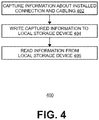
- FIG. 4 comprises a high-level flow chart illustrating one exemplary embodiment of a method 400 of locally storing information about fixed cabling.
- the embodiment of method 400 shown in FIG. 4 is described here as being implemented using the AIM system 100 of FIG. 1A , though it is to be understood that other embodiments can be implemented in other ways.
- method 400 shown in FIG. 4 is described here as being performed in connection with two technicians installing a connection between a port 106 of an item of patching equipment and a port 146 of other equipment 144 (which includes a fixed cable 142) and, in connection therewith, using cable testers 152 to test and verify the installed connection.
- Method 400 comprises capturing information about the installed connection and cabling (block 402).
- two technicians install a connection between an item of patching equipment 102 and an item of other equipment 144.
- the connection includes a fixed cable 142.
- the connection is terminated at the rear (or non-patching) side of the patching equipment 102 and of the other equipment 144 and is coupled, by the patching equipment 102 and the other equipment 144, respectively, to the port 106 and 146 on the front (or patching) side.
- the technicians use cable testers 152 to test and verify the installed connection. This can be done as described above in connection with FIG. 2 and can involve capturing identification and testing information using the cable testers 152.
- Method 400 further comprises writing at least some of the captured information to a local storage device 184 (block 404).
- the technician positioned near the port 106 of the patching equipment 102 can uses the user-interface of the cable tester 152 to cause it to write information that relates to the connection and cabling to the storage device 184 in the item of patching equipment 102 using the wireless interface 186. Also, the technician positioned near the other equipment 144 can use the user-interface of the cable tester 152 to cause it to write information that relates to the connection and cabling to the storage device 184 in the other equipment 144 using the wireless interface 186.
- the cable testers 152 include a wireless interface 180 that are compatible with the wireless interfaces 186 in the item of patching equipment 102 and other equipment 144.
- the wireless interfaces 186 in the item of patching equipment 102 and other equipment 144 use NFC technology.
- the wireless interface 180 of the cable testers 152 implement NFC technology for powering the wireless interfaces 186 and the storage devices 184 and for writing and reading information to and from the storage devices 184 using NFC wireless links.
- Various schemes can be used for storing information in the storage devices 184. For example, the information currently stored in the storage device 184 can be read. If the read information includes any information for the current port, that information can be replaced with the most-recent information that has been captured by the cable tester 152. If the read information does not include any information for the current port, the most-recent information for the port that has been captured by the cable tester 152 can be added to the read information. Then, information read from the storage device 184 along with any updated or added information for the current port is written back to the storage device 184. Other schemes can be used.
- Method 400 further comprises reading information from the storage device 184 (block 406).
- a portable device such as a smartphone or tablet 188) can be positioned near the wireless interface 186 of the current item of patching equipment 102 or the current item of other equipment 144 in order to read information about the ports and associated fixed connections and cabling stored in the associated storage device 184.
- each such read transaction can involve all of the information stored in the storage device 184 being read from it.
- reading information from the associated storage device 184 would involve reading the information for all of the ports 106.
- Other schemes can be used.
- information about the installed connection and fixed cabling can be locally stored in a storage device 184 associated with, and local to, the relevant ports. Thereafter, at an appropriate and convenient time, the stored information can read by a device (such as a smartphone or tablet 188) that is near one of the relevant ports. This can be done to obtain information about the port and the associated connection and fixed cabling without having to access the AIM system 138 and AIM database 140. This is useful in situations where the AIM system 138 has not been configured and/or where the AIM database 140 has not been created or populated. This is also useful in situations where the AIM system 138 and the AIM database 140 are not available.
- Embodiments of method 400 are able to provide these advantages even though power is not available at the patching equipment 102 or the other equipment 144. In the case of the patching equipment 102, this can occur, for example, during the initial installation of the AIM system 100 or during major changes to the AIM system 100. Wall outlets and consolidation points typically are not otherwise powered. In all of these situations, a technician using a portable device is still able to write information to and read information from the storage devices 184.
- each storage device 184 and wireless interface 186 in some of the patching equipment 102 or other equipment 144 can be configured to transmit a beacon that includes at least some of the information stored in the storage device 184.
- each storage device 184 and wireless interface 186 can be configured to join a mesh network (including, for example, other similarly configured patching equipment 102 or other equipment 144 and a gateway 187 connected to an external network 136) to enable a remote external device to write information to and read information from the storage device 184 using the wireless interface 186.
- the AIM manager 138 can access information stored in the storage device 184 via the gateway 187 and the mesh network.
- a suitable mesh networking protocol can be used (for example, BLUETOOTH LOW ENERGY).
- methods 200, 300, and 400 are shown in FIGS. 2 , 3 , and 4 as separate methods, it is to be understood that methods 200, 300, and 400 can be combined or otherwise used together.
- the methods and techniques described here may be implemented in digital electronic circuitry, or with a programmable processor (for example, a special-purpose processor or a general-purpose processor such as a computer) firmware, software, or in combinations of them.
- Apparatus embodying these techniques may include appropriate input and output devices, a programmable processor, and a storage medium tangibly embodying program instructions for execution by the programmable processor.
- a process embodying these techniques may be performed by a programmable processor executing a program of instructions to perform desired functions by operating on input data and generating appropriate output.
- the techniques may advantageously be implemented in one or more programs that are executable on a programmable system including at least one programmable processor coupled to receive data and instructions from, and to transmit data and instructions to, a data storage system, at least one input device, and at least one output device.
- a processor will receive instructions and data from a read-only memory and/or a random access memory.
- Storage devices suitable for tangibly embodying computer program instructions and data include all forms of non-volatile memory, including by way of example semiconductor memory devices, such as EPROM, EEPROM, and flash memory devices; magnetic disks such as internal hard disks and removable disks; magneto-optical disks; and DVD disks. Any of the foregoing may be supplemented by, or incorporated in, specially-designed application-specific integrated circuits (ASICs).
- ASICs application-specific integrated circuits
Landscapes
- Engineering & Computer Science (AREA)
- Computer Networks & Wireless Communication (AREA)
- Physics & Mathematics (AREA)
- General Physics & Mathematics (AREA)
- Structure Of Telephone Exchanges (AREA)
Claims (15)
- System (100), umfassend:
Patchinggerät (102), umfassend:einen oder mehrere Anschlüsse (106), an die Kabel angeschlossen werden können;zumindest einen Sensor (108), der zumindest einem der Anschlüsse (106) zugeordnet ist, um zu erkennen, wann ein Kabel (142) mit dem zumindest einen Anschluss (106) verbunden ist; undeine Steuerung (116), die mit dem Patchinggerät (102) kommunikativ gekoppelt ist;wobei die Steuerung (116) dazu ausgelegt ist, Folgendes auszuführen:Erkennen, dass ein Kabel (154) mit dem zumindest einen Anschluss (106) des Patchinggeräts (102) verbunden wurde;Erkennen, dass das Kabel (154) nicht mehr mit dem zumindest einen Anschluss (106) des Patchinggeräts (102) verbunden ist;wobei die Steuerung dadurch gekennzeichnet ist, dass sie in Reaktion auf das Erkennen, dass das Kabel (154) nicht mehr mit dem zumindest einen Anschluss (106) des Patchinggeräts (102) verbunden ist:von einem Kabeltester (152) Informationen herunterlädt, die der festen Verkabelung (142) zugeordnet sind, die mit dem zumindest einen Anschluss (106) des Patchinggeräts (102) gekoppelt ist;die heruntergeladenen Informationen dem zumindest einen Anschluss (106) des Patchinggeräts (102) zuordnet; unddie heruntergeladenen Informationen und die Zuordnungsinformationen an der Steuerung (116) lokal speichert. - System (100) nach Anspruch 1, wobei das Patchinggerät (102) eine Vielzahl von Anschlüssen (106) umfasst.
- System (100) nach Anspruch 1 oder Anspruch 2, wobei der zumindest eine Sensor (108) Folgendem zugeordnet ist: einem einzigen Anschluss (106) des Patchinggeräts (102), allen Anschlüssen (106) des Patchinggeräts (102) oder einer Teilmenge der Anschlüsse (106) des Patchinggeräts (102).
- System (100) nach einem der vorhergehenden Ansprüche, wobei das Patchinggerät (102) eine Vielzahl von Sensoren (108) umfasst, wobei jeder Sensor (108) Folgendem zugeordnet ist: einem einzigen Anschluss (106) des Patchinggeräts (102), allen Anschlüssen (106) des Patchinggeräts (102) oder einer Teilmenge der Anschlüsse (106) des Patchinggeräts (102).
- System (100) nach einem der vorhergehenden Ansprüche, wobei die Steuerung (116) dazu ausgelegt ist, eine Kommunikationsverbindung mit dem Kabeltester (152) herzustellen.
- System (100) nach einem der vorhergehenden Ansprüche, wobei die heruntergeladenen Informationen Identifizierungsinformationen, Ortsinformationen und Testinformationen umfassen.
- System (100) nach einem der vorhergehenden Ansprüche, wobei die feste Verkabelung (142) mit anderen Geräten (144) verbunden ist, wobei die anderen Geräte zumindest eines von einem Auslass, einem Konsolidierungspunkt und einem anderen Element des Patchinggeräts umfasst; und
wobei das andere Gerät (144) ferner eine Speichervorrichtung (184) und eine drahtlose Schnittstelle (186) umfasst, wobei das andere Gerät (144) dazu ausgelegt ist, es einer externen Vorrichtung (188) zu ermöglichen, Informationen in die Speichervorrichtung (184) unter Verwendung der drahtlosen Schnittstelle (186) zu schreiben und aus dieser zu lesen. - System (100) nach einem der vorhergehenden Ansprüche, insbesondere nach Anspruch 7, wobei das andere Gerät (144) einen Auslass (144) umfasst, der eine Frontplatte (147) und einen Anschluss (146) beinhaltet, wobei die Speichervorrichtung (184) an zumindest einem von dem Anschluss (146) des Auslasses (144) und der Frontplatte (147) des Auslasses (144) montiert ist.
- System (100) nach einem der vorhergehenden Ansprüche, insbesondere Anspruch 7, wobei die drahtlose Schnittstelle (186) des anderen Geräts (144) dazu ausgelegt ist, einen Baken zu senden, der zumindest einige der Informationen beinhaltet, die in der Speichervorrichtung (184) gespeichert sind.
- System (100) nach einem der vorhergehenden Ansprüche, insbesondere Anspruch 7, wobei die drahtlose Schnittstelle (186) des anderen Geräts (144) dazu ausgelegt ist, einem Mesh-Netzwerk beizutreten, um es einer externen Vorrichtung zu ermöglichen, Informationen in die Speichervorrichtung (184) unter Verwendung der drahtlosen Schnittstelle (186) zu schreiben und aus dieser zu lesen.
- System (100) nach einem der vorhergehenden Ansprüche, wobei das Patchinggerät (102) ferner eine Speichervorrichtung (184) und eine drahtlose Schnittstelle (186) umfasst, wobei das Patchinggerät (102) dazu ausgelegt ist, es einer externen Vorrichtung zu ermöglichen, Informationen in die Speichervorrichtung (184) unter Verwendung der drahtlosen Schnittstelle (186) zu schreiben und aus dieser zu lesen.
- System (100) nach einem der vorhergehenden Ansprüche, insbesondere Anspruch 11, wobei die drahtlose Schnittstelle (186) des Patchinggeräts (102) dazu ausgelegt ist, einen Baken zu senden, der zumindest einige der Informationen beinhaltet, die in der Speichervorrichtung (184) gespeichert sind.
- System (100) nach einem der vorhergehenden Ansprüche, insbesondere Anspruch 11, wobei die drahtlose Schnittstelle (186) des Patchinggeräts (102) dazu ausgelegt ist, einem Mesh-Netzwerk beizutreten, um es einer externen Vorrichtung zu ermöglichen, Informationen in die Speichervorrichtung (184) unter Verwendung der drahtlosen Schnittstelle (186) zu schreiben und aus dieser zu lesen.
- Verfahren, umfassend;
Erkennen, dass ein Kabel (154) mit einem Anschluss (106) des Patchinggeräts (102) verbunden wurde;
Erkennen, dass das Kabel (154) nicht mehr mit dem Anschluss (106) des Patchinggeräts (102) verbunden ist;
in Reaktion auf das Erkennen, dass das Kabel (154) nicht mehr mit dem Anschluss (106) des Patchinggeräts (102) verbunden ist:Herunterladen, zu einer Steuerung (116), die mit dem Patchinggerät (102) kommunikativ gekoppelt ist, von Informationen von einem Kabeltester (152), der der festen Verkabelung (142) zugeordnet ist, die mit dem Anschluss (106) des Patchinggeräts (102) gekoppelt ist;Zuordnen der heruntergeladenen Informationen zu dem Anschluss (106) des Patchinggeräts; undlokales Speichern der heruntergeladenen Informationen und der Zuordnungsinformationen an der Steuerung (116). - Verfahren nach Anspruch 14, wobei das Erkennen, dass das Kabel (154) mit dem Anschluss (106) des Patchinggeräts (102) verbunden wurde, das Verwenden eines Sensors (108) umfasst, der dem Anschluss (106) zugeordnet ist, um zu erkennen, dass das Kabel (154) mit dem Anschluss (106) verbunden wurde; und
wobei das Erkennen, dass das Kabel (154) nicht mehr mit dem Anschluss (106) des Patchinggeräts (102) verbunden ist, Folgendes umfasst: Verwenden des Sensors (108), der dem Anschluss (106) zugeordnet ist, um zu erkennen, dass das Kabel (154) nicht mehr mit dem Anschluss (106) des Patchinggeräts (102) verbunden ist.
Priority Applications (1)
| Application Number | Priority Date | Filing Date | Title |
|---|---|---|---|
| EP20201421.3A EP3787306A1 (de) | 2018-03-06 | 2019-03-06 | Automatisierte erfassung von informationen über eine feste verkabelung |
Applications Claiming Priority (1)
| Application Number | Priority Date | Filing Date | Title |
|---|---|---|---|
| US201862639371P | 2018-03-06 | 2018-03-06 |
Related Child Applications (2)
| Application Number | Title | Priority Date | Filing Date |
|---|---|---|---|
| EP20201421.3A Division-Into EP3787306A1 (de) | 2018-03-06 | 2019-03-06 | Automatisierte erfassung von informationen über eine feste verkabelung |
| EP20201421.3A Division EP3787306A1 (de) | 2018-03-06 | 2019-03-06 | Automatisierte erfassung von informationen über eine feste verkabelung |
Publications (2)
| Publication Number | Publication Date |
|---|---|
| EP3537723A1 EP3537723A1 (de) | 2019-09-11 |
| EP3537723B1 true EP3537723B1 (de) | 2020-12-16 |
Family
ID=65817726
Family Applications (2)
| Application Number | Title | Priority Date | Filing Date |
|---|---|---|---|
| EP20201421.3A Withdrawn EP3787306A1 (de) | 2018-03-06 | 2019-03-06 | Automatisierte erfassung von informationen über eine feste verkabelung |
| EP19161100.3A Not-in-force EP3537723B1 (de) | 2018-03-06 | 2019-03-06 | Automatisierte erfassung von informationen über eine feste verkabelung |
Family Applications Before (1)
| Application Number | Title | Priority Date | Filing Date |
|---|---|---|---|
| EP20201421.3A Withdrawn EP3787306A1 (de) | 2018-03-06 | 2019-03-06 | Automatisierte erfassung von informationen über eine feste verkabelung |
Country Status (2)
| Country | Link |
|---|---|
| US (2) | US10938167B2 (de) |
| EP (2) | EP3787306A1 (de) |
Families Citing this family (11)
| Publication number | Priority date | Publication date | Assignee | Title |
|---|---|---|---|---|
| US10938167B2 (en) | 2018-03-06 | 2021-03-02 | Commscope Technologies Llc | Automated capture of information about fixed cabling |
| CN114402626A (zh) * | 2019-09-12 | 2022-04-26 | 康普技术有限责任公司 | 用于布线基础设施的物联网(iot)系统 |
| US10841413B1 (en) * | 2020-01-02 | 2020-11-17 | Spirent Communications, Inc. | Systems and methods for using an audio cross-connect cable for remote mobile device testing |
| US11347955B2 (en) * | 2020-03-09 | 2022-05-31 | Panduit Corp. | Cable management system and method |
| FR3124645A1 (fr) * | 2021-06-25 | 2022-12-30 | Nexans | Assistance à l’installation d’un réseau électrique câblé |
| KR102587756B1 (ko) * | 2021-09-03 | 2023-10-11 | 김경선 | 커넥터와 연결하는 분배 장치와, 그 연결 상태를 관리하는 서버 장치 및 그 방법들 |
| CN113960496B (zh) * | 2021-09-14 | 2023-08-18 | 联想(北京)有限公司 | 一种线路诊断方法以及装置 |
| US12200516B2 (en) | 2022-07-05 | 2025-01-14 | Spirent Communications, Inc. | E911 backhaul routing tests remote from coverage area |
| US12574766B2 (en) | 2022-07-05 | 2026-03-10 | Spirent Communications, Inc. | Inter-core transport audio quality testing remote from testing site |
| US12574456B2 (en) | 2022-07-05 | 2026-03-10 | Spirent Communications, Inc. | Transport audio quality testing remote from testing site |
| US12413318B2 (en) | 2022-07-05 | 2025-09-09 | Spirent Communications, Inc. | Over-the-air audio quality testing remote from testing site |
Family Cites Families (85)
| Publication number | Priority date | Publication date | Assignee | Title |
|---|---|---|---|---|
| US5483467A (en) | 1992-06-10 | 1996-01-09 | Rit Technologies, Ltd. | Patching panel scanner |
| US5406260A (en) | 1992-12-18 | 1995-04-11 | Chrimar Systems, Inc. | Network security system for detecting removal of electronic equipment |
| US5394503A (en) | 1993-10-08 | 1995-02-28 | Data Switch Corporation | Optical fiber connection monitoring apparatus, patch panel control system and method of using same |
| US5550755A (en) | 1994-07-14 | 1996-08-27 | Martin; B. Morgan | Apparatus and method for patch recording and recall |
| IL110859A (en) | 1994-09-04 | 1999-12-31 | Rit Techn Ltd | Interconnection monitor system for telephone network |
| CA2162515C (en) | 1994-12-22 | 2000-03-21 | Leonard George Cohen | Jumper tracing system |
| US5764043A (en) | 1996-12-20 | 1998-06-09 | Siecor Corporation | Traceable patch cord and connector assembly and method for locating patch cord ends |
| US6002331A (en) | 1998-07-20 | 1999-12-14 | Laor; Herzel | Method and apparatus for identifying and tracking connections of communication lines |
| US6532215B1 (en) | 1998-08-07 | 2003-03-11 | Cisco Technology, Inc. | Device and method for network communications and diagnostics |
| US6473608B1 (en) | 1999-01-12 | 2002-10-29 | Powerdsine Ltd. | Structure cabling system |
| US6424710B1 (en) | 1999-02-10 | 2002-07-23 | Avaya Technology Corp. | Method and device for detecting the presence of a patch cord connector in a telecommunications patch system using passive detection sensors |
| US6522737B1 (en) | 1999-02-10 | 2003-02-18 | Avaya Technology Corp. | System and method of operation for a telecommunications patch system |
| US6330307B1 (en) | 1999-02-10 | 2001-12-11 | Avaya Technology Corp. | Display panel overlay structure and method for tracing interface modules in a telecommunications patch system |
| US6285293B1 (en) | 1999-02-10 | 2001-09-04 | Avaya Technology Corp. | System and method for addressing and tracing patch cords in a dedicated telecommunications system |
| US6350148B1 (en) | 1999-02-10 | 2002-02-26 | Avaya Technology Corp. | Method and device for detecting the presence of a patch cord connector in a telecommunications patch system |
| ES2272272T3 (es) | 1999-04-06 | 2007-05-01 | Itracs Corporation | Sistema para motorizar un modelo de conexion de puertos de datos. |
| US6222908B1 (en) | 1999-09-23 | 2001-04-24 | Avaya Technology Corp. | Method and device for identifying a specific patch cord connector as it is introduced into, or removed from, a telecommunications patch system |
| US6784802B1 (en) | 1999-11-04 | 2004-08-31 | Nordx/Cdt, Inc. | Real time monitoring of cable patch panel |
| US6961675B2 (en) | 2000-03-14 | 2005-11-01 | Itracs Corporation | System for monitoring connection pattern of data ports |
| US20020090858A1 (en) | 2000-11-22 | 2002-07-11 | Caveney Jack E. | Network revision system with probe |
| US6705707B2 (en) | 2001-01-16 | 2004-03-16 | Fuji Photo Film Co., Ltd. | Ink jet recording method and device having meniscus control |
| US7289449B1 (en) | 2001-03-20 | 2007-10-30 | 3Com Corporation | Device and method for managing fault detection and fault isolation in voice and data networks |
| US6750643B2 (en) | 2002-08-05 | 2004-06-15 | Richard Hwang | Group wiring patching system and method for wire pair identification |
| IL152768A (en) | 2002-11-11 | 2008-04-13 | Rit Techn Ltd | Retrofit kit for interconnect cabling system |
| US7139668B2 (en) | 2003-05-12 | 2006-11-21 | Simmonds Precision Products, Inc. | Wire event detection |
| US7106071B2 (en) | 2003-06-11 | 2006-09-12 | Broadcom Corporation | Cable diagnostics using time domain reflectometry and applications using the same |
| US7164274B2 (en) | 2003-06-11 | 2007-01-16 | Broadcom Corporation | Cable diagnostics using time domain reflectometry and applications using the same |
| TW200605454A (en) | 2004-01-20 | 2006-02-01 | Siemon Co | Patch panel system |
| US7170393B2 (en) | 2004-03-30 | 2007-01-30 | Lucent Technologies, Inc. | Method and apparatus for the automatic determination of network cable connections using RFID tags and an antenna grid |
| EP1743490B1 (de) | 2004-05-03 | 2011-09-14 | Panduit Corporation | Elektrisch angetriebene schalttafel |
| GB0410682D0 (en) | 2004-05-12 | 2004-06-16 | Dkr Electrical Services Lancas | Non contact cable testing |
| US6968994B1 (en) | 2004-07-06 | 2005-11-29 | Nortel Networks Ltd | RF-ID for cable management and port identification |
| US7719992B1 (en) | 2004-07-14 | 2010-05-18 | Cisco Tchnology, Ink. | System for proactive time domain reflectometry |
| US7664232B2 (en) | 2004-10-05 | 2010-02-16 | Rit Technologies Ltd. | Method and system for distance measurements |
| US7297018B2 (en) | 2004-11-03 | 2007-11-20 | Panduit Corp. | Method and apparatus for patch panel patch cord documentation and revision |
| WO2006069214A1 (en) | 2004-12-21 | 2006-06-29 | Commscope Inc. Of North Carolina | Methods, systems and computer program products for notifying telecommunications system technicians of pending work orders |
| US20060164998A1 (en) | 2005-01-26 | 2006-07-27 | Broadcom Corporation | System and method for detecting added network connections including wiretaps |
| US7234944B2 (en) | 2005-08-26 | 2007-06-26 | Panduit Corp. | Patch field documentation and revision systems |
| US7811119B2 (en) | 2005-11-18 | 2010-10-12 | Panduit Corp. | Smart cable provisioning for a patch cord management system |
| GB0524938D0 (en) | 2005-12-07 | 2006-01-18 | Mazzoleri Silvano | Improvements in and relating to cable connector port structures |
| US7217152B1 (en) | 2005-12-19 | 2007-05-15 | Telect Inc. | Patch panel with tracer |
| US7769090B2 (en) | 2006-03-31 | 2010-08-03 | Texas Instruments Incorporated | Active link cable diagnostics |
| US8116434B2 (en) | 2006-11-29 | 2012-02-14 | Commscope, Inc. Of North Carolina | Telecommunications patching system that facilitates detection and identification of patch cords |
| US7738387B2 (en) | 2007-01-17 | 2010-06-15 | Broadcom Corporation | System and method for diagnosing a cabling infrastructure using a PHY |
| US7573254B2 (en) | 2007-04-12 | 2009-08-11 | Commscope Inc. Of North Carolina | Systems and methods of identifying patch cord connections in a communications patching system using common mode transmission |
| US20080265915A1 (en) | 2007-04-24 | 2008-10-30 | Hewlett-Packard Development Company, L.P. | Method of detecting a network cabling change |
| US7737704B2 (en) | 2007-06-12 | 2010-06-15 | Broadcom Corporation | System and method for using a PHY to locate a thermal signature in a cable plant for diagnostic, enhanced, and higher power applications |
| US8461964B2 (en) | 2007-10-12 | 2013-06-11 | Commscope, Inc. Of North Carolina | Communications patching systems with radio frequency identification antenna switching circuits |
| US8490161B2 (en) | 2008-01-07 | 2013-07-16 | Commscope Inc., Of North Carolina | Methods, systems and computer program products for provisioning VLAN services in a network |
| US20090175195A1 (en) | 2008-01-07 | 2009-07-09 | Commscope, Inc. North Carolina | Methods, systems and computer program products for using time domain reflectometry signatures to monitor network communication lines |
| WO2009124069A1 (en) | 2008-04-02 | 2009-10-08 | Marvell World Trade Ltd. | Reduced power transmission |
| US8382501B2 (en) | 2008-07-08 | 2013-02-26 | Commscope Inc. Of North Carolina | Systems and methods of identifying connections in a communications patching system using common-mode channel signal transmissions |
| US20100011097A1 (en) | 2008-07-11 | 2010-01-14 | Terry Cobb | Methods of Using Control Communications to Identify Devices that are Connected Through a Communications Patching System and Related Communications Patching Systems |
| US20100085156A1 (en) | 2008-10-07 | 2010-04-08 | Commscope, Inc. | Apparatus, systems and methods for identifying patch cords in high density connector port configurations |
| CN102210061B (zh) | 2008-10-07 | 2015-08-05 | 莫列斯公司 | 用于有线网络管理系统中的端帽 |
| GB2468925B (en) | 2009-03-27 | 2014-01-01 | Cable Sense Ltd | Apparatuses and methods for coupling a signal to and/or from a cable |
| US9123217B2 (en) * | 2009-06-29 | 2015-09-01 | Commscope, Inc. Of North Carolina | Methods of automatically recording patching changes at passive patch panels and network equipment |
| CN102598705B (zh) | 2009-06-29 | 2015-06-17 | 北卡罗来纳科姆斯科普公司 | 接插板、接插板系统和显示接插线连接信息的方法 |
| US9538262B2 (en) * | 2009-08-21 | 2017-01-03 | Commscope, Inc. Of North Carolina | Systems, equipment and methods for automatically tracking cable connections and for identifying work area devices and related methods of operating communications networks |
| WO2011056541A1 (en) | 2009-10-26 | 2011-05-12 | Panduit Corp. | Physical layer management using rfid and near-field coupling techniques |
| US8913746B2 (en) | 2010-12-22 | 2014-12-16 | Schneider Electric It Corporation | Wireless communication system and method |
| US8952707B2 (en) | 2011-01-21 | 2015-02-10 | Commscope, Inc. Of North Carolina | Plug insertion detection circuits and related methods and communications connectors |
| US8954763B2 (en) | 2011-01-27 | 2015-02-10 | Commscope, Inc. Of North Carolina | Automated infrastructure management systems and methods for enabling real time energy management |
| US8618927B2 (en) | 2011-08-24 | 2013-12-31 | At&T Intellectual Property I, L.P. | Methods, systems, and products for notifications in security systems |
| CN103814626B (zh) | 2011-09-26 | 2016-06-15 | 皇家飞利浦有限公司 | 具有多点传感器校准的开环闭环集成日光和人造光控制 |
| US9678133B2 (en) | 2012-03-12 | 2017-06-13 | Commscope, Inc. Of North Carolina | Intelligent patching systems and methods using electrical cable diagnostic tests and inference-based mapping techniques |
| US9473361B2 (en) | 2012-07-11 | 2016-10-18 | Commscope Technologies Llc | Physical layer management at a wall plate device |
| WO2014011904A2 (en) | 2012-07-11 | 2014-01-16 | Adc Telecommunications, Inc. | Telecommunications cabinet modularization |
| EP2796903B1 (de) | 2013-04-24 | 2018-12-26 | Rockwell Automation Safety AG | Optische Einheit, Lichtvorhang und Verfahren zur Zuordnung einer individuellen Adresse |
| US20150073613A1 (en) * | 2013-09-10 | 2015-03-12 | Max Chin Li | Smart cloud service power outlet with surge protection and cloud service power consumption monitoring system |
| JP6349880B2 (ja) | 2014-03-31 | 2018-07-04 | ブラザー工業株式会社 | 通信装置 |
| US20150308863A1 (en) | 2014-04-25 | 2015-10-29 | Verizon Patent And Licensing Inc. | Optical-sensor-equipped cut sleeve for connector adapter |
| JP6252373B2 (ja) * | 2014-06-20 | 2017-12-27 | 日立金属株式会社 | 通信ケーブル用コネクタ及びコネクタ付き通信ケーブル |
| KR102023382B1 (ko) * | 2015-02-03 | 2019-09-23 | 주식회사 지오라인 | 사용자인증 콘센트 또는 커넥터, 전력중개용 모듈 및 전력수요장치 |
| US9565659B1 (en) * | 2015-06-05 | 2017-02-07 | Sprint Communications Company L.P. | Wireless beacon for embedding in building infrastructure |
| TWI575363B (zh) * | 2015-07-28 | 2017-03-21 | 碩天科技股份有限公司 | 具有可擴充插座的電源設備及其插座擴充方法 |
| US20170070090A1 (en) * | 2015-09-08 | 2017-03-09 | Weifield Group Consulting | Smart electrical outlet |
| US10820444B2 (en) | 2016-08-31 | 2020-10-27 | Commscope Technologies Llc | Systems and methods for monitoring the presence of rack mounted equipment |
| WO2019006026A1 (en) | 2017-06-28 | 2019-01-03 | Commscope Technologies Llc | SYSTEMS AND METHODS FOR CONNECTIVITY WALL OUTPUTS MANAGED WITH LOW ENERGY WIRELESS COMMUNICATION |
| WO2019028418A1 (en) | 2017-08-03 | 2019-02-07 | Commscope Technologies Llc | METHODS FOR AUTOMATIC RECORDING OF CONNECTION CHANGES AT PASSIVE CONNECTION TABLE AND NETWORK EQUIPMENT LEVELS |
| CA2976871A1 (en) | 2017-08-18 | 2019-02-18 | AquaSwift Inc. | Method and system for data collection and data management |
| US10410484B2 (en) | 2018-01-19 | 2019-09-10 | Comcast Cable Communications, Llc | Security systems and methods for structures with moveable components |
| US10938167B2 (en) | 2018-03-06 | 2021-03-02 | Commscope Technologies Llc | Automated capture of information about fixed cabling |
| US11431136B2 (en) | 2018-08-23 | 2022-08-30 | Stoneridge Control Devices, Inc. | System and method for detecting the position of a cover of an electrical connector |
| WO2020117449A1 (en) | 2018-12-04 | 2020-06-11 | Commscope Technologies Llc | Systems and methods for integrated documentation of network design and implementation |
-
2019
- 2019-03-05 US US16/293,536 patent/US10938167B2/en not_active Expired - Fee Related
- 2019-03-06 EP EP20201421.3A patent/EP3787306A1/de not_active Withdrawn
- 2019-03-06 EP EP19161100.3A patent/EP3537723B1/de not_active Not-in-force
-
2021
- 2021-01-28 US US17/161,166 patent/US11450993B2/en active Active
Non-Patent Citations (1)
| Title |
|---|
| None * |
Also Published As
| Publication number | Publication date |
|---|---|
| US20190280438A1 (en) | 2019-09-12 |
| EP3537723A1 (de) | 2019-09-11 |
| US10938167B2 (en) | 2021-03-02 |
| EP3787306A1 (de) | 2021-03-03 |
| US11450993B2 (en) | 2022-09-20 |
| US20210151940A1 (en) | 2021-05-20 |
Similar Documents
| Publication | Publication Date | Title |
|---|---|---|
| US11450993B2 (en) | Automated capture of information about fixed cabling | |
| US10262656B2 (en) | Multi-tier intelligent infrastructure management systems for communications systems and related equipment and methods | |
| US12282443B2 (en) | Rack controller with native support for intelligent patching equipment installed in multiple racks | |
| US9123217B2 (en) | Methods of automatically recording patching changes at passive patch panels and network equipment | |
| CN101142826A (zh) | 使用rfid标签来检测和识别跳线互连的电信接线系统 | |
| US20210398056A1 (en) | Mobile application for assisting a technician in carrying out an electronic work order | |
| CN104395737A (zh) | 用于识别多芯光缆中的光纤顺序的系统和方法 | |
| US11747876B2 (en) | Systems and methods for network port occupancy state change monitoring using low energy wireless communications | |
| US10210068B2 (en) | Device topology definition system | |
| US10819661B2 (en) | Systems and methods for detecting component rotation within a communication assembly | |
| JP2026067936A (ja) | ケーブル管理システム及び方法 | |
| US11621742B2 (en) | Systems and methods for automated network cabling integrity monitoring | |
| US20240381009A1 (en) | Systems and methods for infrastructure configuration management | |
| CN107239355B (zh) | 用于航天器电连接器插拔防呆看板交互系统和交互方法 | |
| CN102590956A (zh) | 光纤连接器管理装置及方法 |
Legal Events
| Date | Code | Title | Description |
|---|---|---|---|
| PUAI | Public reference made under article 153(3) epc to a published international application that has entered the european phase |
Free format text: ORIGINAL CODE: 0009012 |
|
| STAA | Information on the status of an ep patent application or granted ep patent |
Free format text: STATUS: THE APPLICATION HAS BEEN PUBLISHED |
|
| AK | Designated contracting states |
Kind code of ref document: A1 Designated state(s): AL AT BE BG CH CY CZ DE DK EE ES FI FR GB GR HR HU IE IS IT LI LT LU LV MC MK MT NL NO PL PT RO RS SE SI SK SM TR |
|
| AX | Request for extension of the european patent |
Extension state: BA ME |
|
| STAA | Information on the status of an ep patent application or granted ep patent |
Free format text: STATUS: REQUEST FOR EXAMINATION WAS MADE |
|
| 17P | Request for examination filed |
Effective date: 20200305 |
|
| RBV | Designated contracting states (corrected) |
Designated state(s): AL AT BE BG CH CY CZ DE DK EE ES FI FR GB GR HR HU IE IS IT LI LT LU LV MC MK MT NL NO PL PT RO RS SE SI SK SM TR |
|
| GRAP | Despatch of communication of intention to grant a patent |
Free format text: ORIGINAL CODE: EPIDOSNIGR1 |
|
| STAA | Information on the status of an ep patent application or granted ep patent |
Free format text: STATUS: GRANT OF PATENT IS INTENDED |
|
| GRAJ | Information related to disapproval of communication of intention to grant by the applicant or resumption of examination proceedings by the epo deleted |
Free format text: ORIGINAL CODE: EPIDOSDIGR1 |
|
| STAA | Information on the status of an ep patent application or granted ep patent |
Free format text: STATUS: REQUEST FOR EXAMINATION WAS MADE |
|
| GRAP | Despatch of communication of intention to grant a patent |
Free format text: ORIGINAL CODE: EPIDOSNIGR1 |
|
| STAA | Information on the status of an ep patent application or granted ep patent |
Free format text: STATUS: GRANT OF PATENT IS INTENDED |
|
| INTG | Intention to grant announced |
Effective date: 20200616 |
|
| INTC | Intention to grant announced (deleted) | ||
| INTG | Intention to grant announced |
Effective date: 20200714 |
|
| GRAS | Grant fee paid |
Free format text: ORIGINAL CODE: EPIDOSNIGR3 |
|
| GRAA | (expected) grant |
Free format text: ORIGINAL CODE: 0009210 |
|
| STAA | Information on the status of an ep patent application or granted ep patent |
Free format text: STATUS: THE PATENT HAS BEEN GRANTED |
|
| AK | Designated contracting states |
Kind code of ref document: B1 Designated state(s): AL AT BE BG CH CY CZ DE DK EE ES FI FR GB GR HR HU IE IS IT LI LT LU LV MC MK MT NL NO PL PT RO RS SE SI SK SM TR |
|
| REG | Reference to a national code |
Ref country code: GB Ref legal event code: FG4D |
|
| REG | Reference to a national code |
Ref country code: IE Ref legal event code: FG4D |
|
| REG | Reference to a national code |
Ref country code: DE Ref legal event code: R096 Ref document number: 602019001715 Country of ref document: DE |
|
| REG | Reference to a national code |
Ref country code: AT Ref legal event code: REF Ref document number: 1346659 Country of ref document: AT Kind code of ref document: T Effective date: 20210115 Ref country code: CH Ref legal event code: NV Representative=s name: MURGITROYD AND COMPANY, CH |
|
| PG25 | Lapsed in a contracting state [announced via postgrant information from national office to epo] |
Ref country code: RS Free format text: LAPSE BECAUSE OF FAILURE TO SUBMIT A TRANSLATION OF THE DESCRIPTION OR TO PAY THE FEE WITHIN THE PRESCRIBED TIME-LIMIT Effective date: 20201216 Ref country code: FI Free format text: LAPSE BECAUSE OF FAILURE TO SUBMIT A TRANSLATION OF THE DESCRIPTION OR TO PAY THE FEE WITHIN THE PRESCRIBED TIME-LIMIT Effective date: 20201216 Ref country code: NO Free format text: LAPSE BECAUSE OF FAILURE TO SUBMIT A TRANSLATION OF THE DESCRIPTION OR TO PAY THE FEE WITHIN THE PRESCRIBED TIME-LIMIT Effective date: 20210316 Ref country code: GR Free format text: LAPSE BECAUSE OF FAILURE TO SUBMIT A TRANSLATION OF THE DESCRIPTION OR TO PAY THE FEE WITHIN THE PRESCRIBED TIME-LIMIT Effective date: 20210317 |
|
| REG | Reference to a national code |
Ref country code: AT Ref legal event code: MK05 Ref document number: 1346659 Country of ref document: AT Kind code of ref document: T Effective date: 20201216 |
|
| REG | Reference to a national code |
Ref country code: NL Ref legal event code: MP Effective date: 20201216 |
|
| PG25 | Lapsed in a contracting state [announced via postgrant information from national office to epo] |
Ref country code: BG Free format text: LAPSE BECAUSE OF FAILURE TO SUBMIT A TRANSLATION OF THE DESCRIPTION OR TO PAY THE FEE WITHIN THE PRESCRIBED TIME-LIMIT Effective date: 20210316 Ref country code: SE Free format text: LAPSE BECAUSE OF FAILURE TO SUBMIT A TRANSLATION OF THE DESCRIPTION OR TO PAY THE FEE WITHIN THE PRESCRIBED TIME-LIMIT Effective date: 20201216 Ref country code: LV Free format text: LAPSE BECAUSE OF FAILURE TO SUBMIT A TRANSLATION OF THE DESCRIPTION OR TO PAY THE FEE WITHIN THE PRESCRIBED TIME-LIMIT Effective date: 20201216 |
|
| PGFP | Annual fee paid to national office [announced via postgrant information from national office to epo] |
Ref country code: DE Payment date: 20210329 Year of fee payment: 3 |
|
| PG25 | Lapsed in a contracting state [announced via postgrant information from national office to epo] |
Ref country code: HR Free format text: LAPSE BECAUSE OF FAILURE TO SUBMIT A TRANSLATION OF THE DESCRIPTION OR TO PAY THE FEE WITHIN THE PRESCRIBED TIME-LIMIT Effective date: 20201216 Ref country code: NL Free format text: LAPSE BECAUSE OF FAILURE TO SUBMIT A TRANSLATION OF THE DESCRIPTION OR TO PAY THE FEE WITHIN THE PRESCRIBED TIME-LIMIT Effective date: 20201216 |
|
| REG | Reference to a national code |
Ref country code: LT Ref legal event code: MG9D |
|
| PG25 | Lapsed in a contracting state [announced via postgrant information from national office to epo] |
Ref country code: CZ Free format text: LAPSE BECAUSE OF FAILURE TO SUBMIT A TRANSLATION OF THE DESCRIPTION OR TO PAY THE FEE WITHIN THE PRESCRIBED TIME-LIMIT Effective date: 20201216 Ref country code: SM Free format text: LAPSE BECAUSE OF FAILURE TO SUBMIT A TRANSLATION OF THE DESCRIPTION OR TO PAY THE FEE WITHIN THE PRESCRIBED TIME-LIMIT Effective date: 20201216 Ref country code: SK Free format text: LAPSE BECAUSE OF FAILURE TO SUBMIT A TRANSLATION OF THE DESCRIPTION OR TO PAY THE FEE WITHIN THE PRESCRIBED TIME-LIMIT Effective date: 20201216 Ref country code: EE Free format text: LAPSE BECAUSE OF FAILURE TO SUBMIT A TRANSLATION OF THE DESCRIPTION OR TO PAY THE FEE WITHIN THE PRESCRIBED TIME-LIMIT Effective date: 20201216 Ref country code: LT Free format text: LAPSE BECAUSE OF FAILURE TO SUBMIT A TRANSLATION OF THE DESCRIPTION OR TO PAY THE FEE WITHIN THE PRESCRIBED TIME-LIMIT Effective date: 20201216 Ref country code: RO Free format text: LAPSE BECAUSE OF FAILURE TO SUBMIT A TRANSLATION OF THE DESCRIPTION OR TO PAY THE FEE WITHIN THE PRESCRIBED TIME-LIMIT Effective date: 20201216 Ref country code: PT Free format text: LAPSE BECAUSE OF FAILURE TO SUBMIT A TRANSLATION OF THE DESCRIPTION OR TO PAY THE FEE WITHIN THE PRESCRIBED TIME-LIMIT Effective date: 20210416 |
|
| PG25 | Lapsed in a contracting state [announced via postgrant information from national office to epo] |
Ref country code: AT Free format text: LAPSE BECAUSE OF FAILURE TO SUBMIT A TRANSLATION OF THE DESCRIPTION OR TO PAY THE FEE WITHIN THE PRESCRIBED TIME-LIMIT Effective date: 20201216 Ref country code: PL Free format text: LAPSE BECAUSE OF FAILURE TO SUBMIT A TRANSLATION OF THE DESCRIPTION OR TO PAY THE FEE WITHIN THE PRESCRIBED TIME-LIMIT Effective date: 20201216 |
|
| REG | Reference to a national code |
Ref country code: DE Ref legal event code: R097 Ref document number: 602019001715 Country of ref document: DE |
|
| PG25 | Lapsed in a contracting state [announced via postgrant information from national office to epo] |
Ref country code: IS Free format text: LAPSE BECAUSE OF FAILURE TO SUBMIT A TRANSLATION OF THE DESCRIPTION OR TO PAY THE FEE WITHIN THE PRESCRIBED TIME-LIMIT Effective date: 20210416 |
|
| PLBE | No opposition filed within time limit |
Free format text: ORIGINAL CODE: 0009261 |
|
| STAA | Information on the status of an ep patent application or granted ep patent |
Free format text: STATUS: NO OPPOSITION FILED WITHIN TIME LIMIT |
|
| PG25 | Lapsed in a contracting state [announced via postgrant information from national office to epo] |
Ref country code: AL Free format text: LAPSE BECAUSE OF FAILURE TO SUBMIT A TRANSLATION OF THE DESCRIPTION OR TO PAY THE FEE WITHIN THE PRESCRIBED TIME-LIMIT Effective date: 20201216 Ref country code: MC Free format text: LAPSE BECAUSE OF FAILURE TO SUBMIT A TRANSLATION OF THE DESCRIPTION OR TO PAY THE FEE WITHIN THE PRESCRIBED TIME-LIMIT Effective date: 20201216 Ref country code: IT Free format text: LAPSE BECAUSE OF FAILURE TO SUBMIT A TRANSLATION OF THE DESCRIPTION OR TO PAY THE FEE WITHIN THE PRESCRIBED TIME-LIMIT Effective date: 20201216 |
|
| 26N | No opposition filed |
Effective date: 20210917 |
|
| PG25 | Lapsed in a contracting state [announced via postgrant information from national office to epo] |
Ref country code: DK Free format text: LAPSE BECAUSE OF FAILURE TO SUBMIT A TRANSLATION OF THE DESCRIPTION OR TO PAY THE FEE WITHIN THE PRESCRIBED TIME-LIMIT Effective date: 20201216 |
|
| REG | Reference to a national code |
Ref country code: BE Ref legal event code: MM Effective date: 20210331 |
|
| PG25 | Lapsed in a contracting state [announced via postgrant information from national office to epo] |
Ref country code: ES Free format text: LAPSE BECAUSE OF FAILURE TO SUBMIT A TRANSLATION OF THE DESCRIPTION OR TO PAY THE FEE WITHIN THE PRESCRIBED TIME-LIMIT Effective date: 20201216 Ref country code: LU Free format text: LAPSE BECAUSE OF NON-PAYMENT OF DUE FEES Effective date: 20210306 Ref country code: IE Free format text: LAPSE BECAUSE OF NON-PAYMENT OF DUE FEES Effective date: 20210306 Ref country code: FR Free format text: LAPSE BECAUSE OF NON-PAYMENT OF DUE FEES Effective date: 20210331 |
|
| PG25 | Lapsed in a contracting state [announced via postgrant information from national office to epo] |
Ref country code: SI Free format text: LAPSE BECAUSE OF FAILURE TO SUBMIT A TRANSLATION OF THE DESCRIPTION OR TO PAY THE FEE WITHIN THE PRESCRIBED TIME-LIMIT Effective date: 20201216 |
|
| PG25 | Lapsed in a contracting state [announced via postgrant information from national office to epo] |
Ref country code: IS Free format text: LAPSE BECAUSE OF FAILURE TO SUBMIT A TRANSLATION OF THE DESCRIPTION OR TO PAY THE FEE WITHIN THE PRESCRIBED TIME-LIMIT Effective date: 20210416 |
|
| PG25 | Lapsed in a contracting state [announced via postgrant information from national office to epo] |
Ref country code: BE Free format text: LAPSE BECAUSE OF NON-PAYMENT OF DUE FEES Effective date: 20210331 |
|
| REG | Reference to a national code |
Ref country code: DE Ref legal event code: R119 Ref document number: 602019001715 Country of ref document: DE |
|
| REG | Reference to a national code |
Ref country code: CH Ref legal event code: PL |
|
| PG25 | Lapsed in a contracting state [announced via postgrant information from national office to epo] |
Ref country code: LI Free format text: LAPSE BECAUSE OF NON-PAYMENT OF DUE FEES Effective date: 20220331 Ref country code: DE Free format text: LAPSE BECAUSE OF NON-PAYMENT OF DUE FEES Effective date: 20221001 Ref country code: CH Free format text: LAPSE BECAUSE OF NON-PAYMENT OF DUE FEES Effective date: 20220331 |
|
| PG25 | Lapsed in a contracting state [announced via postgrant information from national office to epo] |
Ref country code: CY Free format text: LAPSE BECAUSE OF FAILURE TO SUBMIT A TRANSLATION OF THE DESCRIPTION OR TO PAY THE FEE WITHIN THE PRESCRIBED TIME-LIMIT Effective date: 20201216 |
|
| PG25 | Lapsed in a contracting state [announced via postgrant information from national office to epo] |
Ref country code: HU Free format text: LAPSE BECAUSE OF FAILURE TO SUBMIT A TRANSLATION OF THE DESCRIPTION OR TO PAY THE FEE WITHIN THE PRESCRIBED TIME-LIMIT; INVALID AB INITIO Effective date: 20190306 |
|
| GBPC | Gb: european patent ceased through non-payment of renewal fee |
Effective date: 20230306 |
|
| PG25 | Lapsed in a contracting state [announced via postgrant information from national office to epo] |
Ref country code: GB Free format text: LAPSE BECAUSE OF NON-PAYMENT OF DUE FEES Effective date: 20230306 |
|
| PG25 | Lapsed in a contracting state [announced via postgrant information from national office to epo] |
Ref country code: GB Free format text: LAPSE BECAUSE OF NON-PAYMENT OF DUE FEES Effective date: 20230306 |
|
| PG25 | Lapsed in a contracting state [announced via postgrant information from national office to epo] |
Ref country code: MK Free format text: LAPSE BECAUSE OF FAILURE TO SUBMIT A TRANSLATION OF THE DESCRIPTION OR TO PAY THE FEE WITHIN THE PRESCRIBED TIME-LIMIT Effective date: 20201216 |
|
| PG25 | Lapsed in a contracting state [announced via postgrant information from national office to epo] |
Ref country code: MT Free format text: LAPSE BECAUSE OF FAILURE TO SUBMIT A TRANSLATION OF THE DESCRIPTION OR TO PAY THE FEE WITHIN THE PRESCRIBED TIME-LIMIT Effective date: 20201216 |
|
| PG25 | Lapsed in a contracting state [announced via postgrant information from national office to epo] |
Ref country code: TR Free format text: LAPSE BECAUSE OF FAILURE TO SUBMIT A TRANSLATION OF THE DESCRIPTION OR TO PAY THE FEE WITHIN THE PRESCRIBED TIME-LIMIT Effective date: 20201216 |