EP3537953B1 - Drahtlose intraluminale vorrichtung und system - Google Patents
Drahtlose intraluminale vorrichtung und system Download PDFInfo
- Publication number
- EP3537953B1 EP3537953B1 EP17808171.7A EP17808171A EP3537953B1 EP 3537953 B1 EP3537953 B1 EP 3537953B1 EP 17808171 A EP17808171 A EP 17808171A EP 3537953 B1 EP3537953 B1 EP 3537953B1
- Authority
- EP
- European Patent Office
- Prior art keywords
- wireless
- elongate member
- flexible elongate
- intraluminal device
- sensor
- Prior art date
- Legal status (The legal status is an assumption and is not a legal conclusion. Google has not performed a legal analysis and makes no representation as to the accuracy of the status listed.)
- Active
Links
Images


Classifications
-
- A—HUMAN NECESSITIES
- A61—MEDICAL OR VETERINARY SCIENCE; HYGIENE
- A61B—DIAGNOSIS; SURGERY; IDENTIFICATION
- A61B5/00—Measuring for diagnostic purposes; Identification of persons
- A61B5/0002—Remote monitoring of patients using telemetry, e.g. transmission of vital signals via a communication network
-
- A—HUMAN NECESSITIES
- A61—MEDICAL OR VETERINARY SCIENCE; HYGIENE
- A61B—DIAGNOSIS; SURGERY; IDENTIFICATION
- A61B5/00—Measuring for diagnostic purposes; Identification of persons
- A61B5/0002—Remote monitoring of patients using telemetry, e.g. transmission of vital signals via a communication network
- A61B5/0015—Remote monitoring of patients using telemetry, e.g. transmission of vital signals via a communication network characterised by features of the telemetry system
- A61B5/002—Monitoring the patient using a local or closed circuit, e.g. in a room or building
-
- A—HUMAN NECESSITIES
- A61—MEDICAL OR VETERINARY SCIENCE; HYGIENE
- A61B—DIAGNOSIS; SURGERY; IDENTIFICATION
- A61B5/00—Measuring for diagnostic purposes; Identification of persons
- A61B5/02—Detecting, measuring or recording for evaluating the cardiovascular system, e.g. pulse, heart rate, blood pressure or blood flow
- A61B5/021—Measuring pressure in heart or blood vessels
- A61B5/0215—Measuring pressure in heart or blood vessels by means inserted into the body
-
- A—HUMAN NECESSITIES
- A61—MEDICAL OR VETERINARY SCIENCE; HYGIENE
- A61B—DIAGNOSIS; SURGERY; IDENTIFICATION
- A61B5/00—Measuring for diagnostic purposes; Identification of persons
- A61B5/02—Detecting, measuring or recording for evaluating the cardiovascular system, e.g. pulse, heart rate, blood pressure or blood flow
- A61B5/026—Measuring blood flow
-
- A—HUMAN NECESSITIES
- A61—MEDICAL OR VETERINARY SCIENCE; HYGIENE
- A61B—DIAGNOSIS; SURGERY; IDENTIFICATION
- A61B5/00—Measuring for diagnostic purposes; Identification of persons
- A61B5/02—Detecting, measuring or recording for evaluating the cardiovascular system, e.g. pulse, heart rate, blood pressure or blood flow
- A61B5/026—Measuring blood flow
- A61B5/0285—Measuring or recording phase velocity of blood waves
-
- A—HUMAN NECESSITIES
- A61—MEDICAL OR VETERINARY SCIENCE; HYGIENE
- A61B—DIAGNOSIS; SURGERY; IDENTIFICATION
- A61B5/00—Measuring for diagnostic purposes; Identification of persons
- A61B5/02—Detecting, measuring or recording for evaluating the cardiovascular system, e.g. pulse, heart rate, blood pressure or blood flow
- A61B5/026—Measuring blood flow
- A61B5/0295—Measuring blood flow using plethysmography, i.e. measuring the variations in the volume of a body part as modified by the circulation of blood therethrough, e.g. impedance plethysmography
-
- A—HUMAN NECESSITIES
- A61—MEDICAL OR VETERINARY SCIENCE; HYGIENE
- A61B—DIAGNOSIS; SURGERY; IDENTIFICATION
- A61B5/00—Measuring for diagnostic purposes; Identification of persons
- A61B5/68—Arrangements of detecting, measuring or recording means, e.g. sensors, in relation to patient
- A61B5/6846—Arrangements of detecting, measuring or recording means, e.g. sensors, in relation to patient specially adapted to be brought in contact with an internal body part, i.e. invasive
- A61B5/6847—Arrangements of detecting, measuring or recording means, e.g. sensors, in relation to patient specially adapted to be brought in contact with an internal body part, i.e. invasive mounted on an invasive device
- A61B5/6851—Guide wires
-
- A—HUMAN NECESSITIES
- A61—MEDICAL OR VETERINARY SCIENCE; HYGIENE
- A61B—DIAGNOSIS; SURGERY; IDENTIFICATION
- A61B5/00—Measuring for diagnostic purposes; Identification of persons
- A61B5/68—Arrangements of detecting, measuring or recording means, e.g. sensors, in relation to patient
- A61B5/6846—Arrangements of detecting, measuring or recording means, e.g. sensors, in relation to patient specially adapted to be brought in contact with an internal body part, i.e. invasive
- A61B5/6847—Arrangements of detecting, measuring or recording means, e.g. sensors, in relation to patient specially adapted to be brought in contact with an internal body part, i.e. invasive mounted on an invasive device
- A61B5/6852—Catheters
-
- A—HUMAN NECESSITIES
- A61—MEDICAL OR VETERINARY SCIENCE; HYGIENE
- A61B—DIAGNOSIS; SURGERY; IDENTIFICATION
- A61B5/00—Measuring for diagnostic purposes; Identification of persons
- A61B5/68—Arrangements of detecting, measuring or recording means, e.g. sensors, in relation to patient
- A61B5/6846—Arrangements of detecting, measuring or recording means, e.g. sensors, in relation to patient specially adapted to be brought in contact with an internal body part, i.e. invasive
- A61B5/6847—Arrangements of detecting, measuring or recording means, e.g. sensors, in relation to patient specially adapted to be brought in contact with an internal body part, i.e. invasive mounted on an invasive device
- A61B5/686—Permanently implanted devices, e.g. pacemakers, other stimulators, biochips
-
- A—HUMAN NECESSITIES
- A61—MEDICAL OR VETERINARY SCIENCE; HYGIENE
- A61B—DIAGNOSIS; SURGERY; IDENTIFICATION
- A61B2505/00—Evaluating, monitoring or diagnosing in the context of a particular type of medical care
- A61B2505/03—Intensive care
-
- A—HUMAN NECESSITIES
- A61—MEDICAL OR VETERINARY SCIENCE; HYGIENE
- A61B—DIAGNOSIS; SURGERY; IDENTIFICATION
- A61B2505/00—Evaluating, monitoring or diagnosing in the context of a particular type of medical care
- A61B2505/05—Surgical care
-
- A—HUMAN NECESSITIES
- A61—MEDICAL OR VETERINARY SCIENCE; HYGIENE
- A61B—DIAGNOSIS; SURGERY; IDENTIFICATION
- A61B2562/00—Details of sensors; Constructional details of sensor housings or probes; Accessories for sensors
- A61B2562/02—Details of sensors specially adapted for in-vivo measurements
- A61B2562/0247—Pressure sensors
-
- A—HUMAN NECESSITIES
- A61—MEDICAL OR VETERINARY SCIENCE; HYGIENE
- A61B—DIAGNOSIS; SURGERY; IDENTIFICATION
- A61B2562/00—Details of sensors; Constructional details of sensor housings or probes; Accessories for sensors
- A61B2562/16—Details of sensor housings or probes; Details of structural supports for sensors
- A61B2562/164—Details of sensor housings or probes; Details of structural supports for sensors the sensor is mounted in or on a conformable substrate or carrier
-
- A—HUMAN NECESSITIES
- A61—MEDICAL OR VETERINARY SCIENCE; HYGIENE
- A61B—DIAGNOSIS; SURGERY; IDENTIFICATION
- A61B2562/00—Details of sensors; Constructional details of sensor housings or probes; Accessories for sensors
- A61B2562/22—Arrangements of medical sensors with cables or leads; Connectors or couplings specifically adapted for medical sensors
- A61B2562/225—Connectors or couplings
- A61B2562/227—Sensors with electrical connectors
-
- A—HUMAN NECESSITIES
- A61—MEDICAL OR VETERINARY SCIENCE; HYGIENE
- A61M—DEVICES FOR INTRODUCING MEDIA INTO, OR ONTO, THE BODY; DEVICES FOR TRANSDUCING BODY MEDIA OR FOR TAKING MEDIA FROM THE BODY; DEVICES FOR PRODUCING OR ENDING SLEEP OR STUPOR
- A61M2205/00—General characteristics of the apparatus
- A61M2205/35—Communication
- A61M2205/3507—Communication with implanted devices, e.g. external control
- A61M2205/3523—Communication with implanted devices, e.g. external control using telemetric means
Definitions
- the present disclosure relates generally to intraluminal functional assessment and, in particular, to providing wireless communication between a function measurement (FM) intraluminal device and a sensing measurement processing system for display and control.
- FM function measurement
- an intraluminal device may include a pressure sensor and/or a flow sensor at the tip of the intraluminal device.
- the intraluminal device may be inserted into a vessel of a patient body and the pressure sensor and/or the flow sensor may measure pressure and/or flow within the vessel.
- indices have been developed for coronary arteries to guide cardiologists in the decision of treating lesions. Examples of pressure-based indices may include fractional flow reserve (FFR) and instantaneous wave free ratio (iFR).
- An example of flow-based indices may include coronary flow reserve (CFR).
- An example of a combination of pressure-based and flow-based indices may include hyperemic stenosis resistance (HSR). These pressure-based and/or flow-based indices can provide better guidance to treatment decisions compared to angiographic assessment alone.
- an intraluminal device may require several wire connections, for example, for receiving power and for communication with a console for display and control.
- the sensors may receive power via the wire connections for performing sensing measurements and the measurements may be output to the console via the wire connections.
- Intraluminal procedures may be performed in catheter labs and office-based labs (OBLs).
- OBLs office-based labs
- the use of intraluminal devices in catheter labs and OBLs increases the number of cables in the catheter labs and OBLs and may clutter the workspace of the catheter labs and the OBLs.
- sterilization is important when operating in a catheter lab or an OBL.
- the connecting and/or disconnecting of an unsterile console or processing system to a sterile intraluminal device may be an issue in the catheter labs and the OBLs.
- the intravascular device is a guide wire with an adhesive filled distal coil.
- a sensing guide wire includes a flexible elongate member; a sensing element coupled to a distal portion of the flexible elongate member; and a flexible element filled with a flexible adhesive extending distally from the sensing element.
- the intravascular device is a guide wire with electrical conductors printed on a solid core wire.
- the electrical conductors are coupled to conductive bands adjacent a proximal portion of the guide wire.
- guidewires of the invention include a body having an inner core and an outer layer with one or more embedded conductors. The conductors are exposed at one or more locations along the body and a conductive material can be layered over the exposed locations. A sensor can also be coupled to the body via the conductive material at one of the exposed locations.
- the intravascular devices are guide-wires that include one or more sensing components and a sensor control module that stores information about the guide-wire. In some instances, the information about the guide-wire stored in the sensor control module is calibration information for a sensing component of the guide-wire. In some embodiments, the intravascular devices are guide-wires that include wireless communication functionality. In some instances, the guide-wires include one or more antennas adjacent a proximal portion of the guide-wire. In some instances, the guidewires include passive radio frequency devices integrated into the guide-wire.
- US 2013/204111 A1 relates to a sensor wire system with an integrated power source and wireless transmission.
- a sensor wire includes a distal end that is inserted into a blood vessel of a patient' s body.
- a sensor that is mounted at the distal end of the sensor wire and an electronics unit of the distal end of the sensor wire transmit information generated by the sensor to a receiver unit outside of the patient's body wirelessly.
- the system further includes a power source, which in one example is mounted to the distal end of the sensor wire, that supplies power to the electronics unit.
- the wire body functions as an antenna for the wireless broadcasting.
- US 2007/179552 A1 relates to an implantable medical device that is configured so that all of the major components including a housing and attached leads are disposed within the vasculature of a patient.
- a tether extends from the housing of the device to an implant location where the tether is secured to tissue outside of the vasculature.
- an intravascular medical device may be implanted at a location remote from final placement, delivered via the vasculature and anchored at the initial entry point.
- WO 2015/085220 A1 relates to an apparatus for intravascular pressure measurement, comprising an elongate body, a first pressure sensor and a centering assembly disposed adjacent the sensor.
- the elongate body has a uniform diameter from the distal end to the proximal end.
- the uniform diameter is 0.89 mm (0.035 inches) or less.
- the elongated body is a catheter having a plurality of reinforcing filaments and the filaments are utilized to electrically connect the sensor to the proximal end.
- Embodiments of the present disclosure provide a wireless intraluminal device.
- the wireless intraluminal device includes a flexible elongate member, sensor assembly mounted at a distal portion of the flexible elongate member, and a wireless transceiver configured in various configurations within the flexible elongate member.
- a wireless intraluminal device includes a flexible elongate member including a proximal portion and a distal portion; a sensor assembly coupled to the distal portion of the flexible elongate member; a cable coupled to the sensor assembly and extending along the flexible elongate member; and a wireless transceiver positioned within the flexible elongate member, wherein the wireless transceiver is in communication with the sensor assembly via the cable.
- the wireless intraluminal device further includes an antenna communicatively coupled to the wireless transceiver.
- the wireless transceiver is positioned within the proximal portion of the flexible elongate member.
- the antenna extends from the wireless transceiver and along an outer surface of the proximal portion of the flexible elongate member.
- the wireless transceiver is positioned within a central portion of flexible elongate member between the proximal portion and the distal portion, and the antenna extends along an outer surface of the proximal portion of the flexible elongate member.
- the wireless transceiver is positioned within a central portion of flexible elongate member between the proximal portion and the distal portion, and the antenna extends within the proximal portion of the flexible elongate member. In some embodiments, the wireless transceiver is positioned within the distal portion of the flexible elongate member, and the antenna extends along an outer surface of the proximal portion of the flexible elongate member.
- the wireless intraluminal device further includes an electrical interface coupled to the proximal portion of the flexible elongate member; and a connector coupled to the proximal portion of the flexible elongate member, wherein the connector includes a power source coupled to the electrical interface, and wherein the power source powers the sensor assembly and the wireless transceiver.
- the connector is detachable from the flexible elongate member.
- the electrical interface includes a first electrical contact coupled to a positive terminal of the power source; and a second electrical contact coupled to a negative terminal of the power source.
- the electrical interface includes a third electrical contact coupled to the antenna.
- the wireless intraluminal device further includes a connector coupled to the proximal portion of the flexible elongate member; and an antenna mechanically coupled to the connector.
- the sensor assembly includes at least one of a pressure sensor or a flow sensor.
- a wireless intraluminal system for treating a patient includes an intraluminal device as defined in claim 1, the system comprising a first wireless communication component including the wireless transceiver and the antenna, a second wireless communication component in communication with the first wireless communication component of the intraluminal device via a wireless link; and a sensor measurement processing component in communication with the second wireless communication component, wherein the first wireless communication component is configured to wirelessly transmit, to the second wireless communication component via the wireless link, a sensor measurement collected by the sensor assembly for physiological data generation at the sensor measurement processing component.
- the wireless intraluminal system further includes a display component in communication with the sensor measurement processing component, wherein the sensor measurement processing component generates physiological data based on the sensor measurement, and wherein the display component displays the physiological data.
- the second wireless communication component wirelessly transmits, to the first wireless communication component via the wireless link, an instruction to control the sensor assembly for the physiological data generation.
- the intraluminal device includes sensor assembly, a flexible elongate member, a wireless communication component, and a detachable battery pack.
- the flexible elongate member includes a proximal portion and a distal portion.
- the sensor assembly is coupled to the distal portion of the flexible elongate member.
- the intraluminal device includes a cable coupled to the sensor assembly and extending along a length of the flexible elongate member.
- the detachable battery pack is coupled to a proximal portion of the flexible elongate member.
- the wireless communication component can wirelessly receive instructions for controlling the sensor assembly.
- the wireless communication component can wirelessly transmit sensor measurements collected by the sensor assembly for analysis, interpretation, and physiological data generation at a processing system.
- the wireless communication component includes a wireless transceiver and an antenna, which may be positioned at various locations within the intraluminal device.
- the disclosed embodiments may provide several benefits over wired intraluminal devices.
- the use of wireless intraluminal devices reduces the number of cables required in a catheter lab, and thus reduces cluttering of catheter lab workspaces.
- galvanic isolation is important and is typically implemented in a patient isolation module (PIM) connecting to an intraluminal device.
- PIM patient isolation module
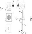
- Fig. 1 is a schematic diagram of a wireless intraluminal system 100, according to aspects of the present disclosure.
- the system 100 may include a wireless intraluminal device 102, a wireless communication component 130, a sensor measurement processing system 132, such as a console and/or a computer, and a monitor 134.
- the intraluminal device 102 may include a flexible elongate member 158, which may be a catheter, a guide wire, or a guide catheter, coupled to a wireless communication component 104.
- the flexible elongate member 158 includes a distal portion 108, a proximal portion 106, and a housing 112 positioned adjacent to the distal portion 108.
- the housing 112 may be positioned at a distance (e.g., about 3 centimeters (cm)) from a distal tip of the intraluminal device 102.
- the housing 112 may include a sensor assembly (shown in Figs. 3 and 4 ), which may include one or more sensors, transducers, and/or other monitoring elements configured to obtain diagnostic information about a vessel 120.
- the intraluminal device 102 may further include a cable (a cable 117 shown in Figs. 2 and 4 ) coupled to the sensor assembly in the housing 112 to provide communication between the sensor assembly and the wireless communication component 104, as described in greater detail herein.
- a cable a cable 117 shown in Figs. 2 and 4
- the wireless communication component 104 is shown to be coupled to the proximal portion 106 of the flexible elongate member 158, the wireless communication component 104 may be configured in various configurations within the intraluminal device 102, as described in greater detail herein.
- the sensor assembly measures physiological characteristics, which may be pressure and/or flow, of fluid in the vessel 120 and the communication cable transfers the sensor measurements to the wireless communication component 104.
- the wireless communication component 104 wirelessly transmits sensor output signals carrying the sensor measurements, for example, in a radio frequency (RF) band, as shown by the RF signals 150.
- RF radio frequency
- the wireless communication component 130 transfers the sensor output signals to the sensor measurement processing system 132.
- the sensor measurement processing system 132 interprets and analyzes the sensor measurements and produces physiological data, graphs, readings and/or diagnostic information for display on the monitor 134.
- the sensor assembly in the housing 112, the wireless communication component 104, and associated components for signal controls and transfers are described in greater detail herein.
- the sensor measurement processing system 132 can include a processor and a memory.
- the sensor measurement processing system 132 can be operable to facilitate the features of the system 100 described herein.
- the processor can execute computer readable instructions stored on the non-transitory tangible computer readable medium.
- the wireless communication components 104 and 130 may include substantially similar functional components, but may have different physical form factors and arrangements.
- the wireless communication components 104 and 130 may operate at a data rate in a range of a few kilobits per second (kbps).
- Some examples of wireless communication protocols suitable for transferring functional measurements may include Bluetooth, Zigbee, and ultra-wideband (UWB).
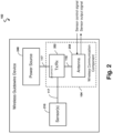
- Fig. 2 is a schematic diagram illustrating the wireless intraluminal device 102 architecture, according to aspects of the present disclosure.
- Fig. 2 provides a more detail view of the internal components of the intraluminal device 102.
- the intraluminal device 102 includes one or more sensors 210, a power source 240, and the wireless communication component 104.
- the sensors 210 may include pressure and/or flow sensors and associated electronics (e.g., a low noise amplifier (LNA)).
- the sensors 210 may be part of the sensor assembly housed in the housing 112.
- the power source 240 may be a battery pack, super capacitors, or any suitable electrical energy storage that powers the sensors 210 and the wireless communication component 104.
- the sensors 210, the wireless communication component 104, and the power source may be coupled via a cable 117.
- the wireless communication component 104 may communicate with the sensors 210 via the cable 117.
- the communication may be bidirectional including transfer of control signals for operating the intraluminal device 102 and sensor measurements collected by the sensors 210.
- the wireless communication component 104 and the sensors 210 may receive power from the power source 240 via the cable 117.
- the wireless communication component 104 includes a transceiver (Tx/Rx) 252 and an antenna 254.
- the transceiver 252 may include hardware and/or software configured to perform data framing, data encoding/decoding, scrambling/descrambling, modulation/demodulation, and/or error encoding/decoding, for example, according to a predetermined wireless communication protocol, such as Bluetooth, Zigbee, or UWB.
- the transceiver 252 may include analog-to-digital converters (ADCs) and digital-to-analog converters (DACs).
- ADCs analog-to-digital converters
- DACs digital-to-analog converters
- the antenna 254 may be constructed from a metal thin film or a metal thin wire.
- the antenna 254 may have any suitable dimension and may vary depending on the wireless technology in use and the specific design. In some embodiments, the antenna 254 may have a length between about 30 millimeters (mm) to about 60 mm.
- the transceiver 252 and the antenna 254 may be arranged in various configurations within the intraluminal device 102, as described in greater detail herein. According to the invention, wireless transceiver 252 is positioned within flexible elongate member 158, and antenna 254 extends along an outer surface of the proximal portion of the flexible elongate member.
- the intraluminal device 102 may include other components and/or circuitries, such as voltage signal converters, ADCs, DACs, line drivers, amplifiers, encoder/decoder logics, for facilitating the operations of the intraluminal device 102.
- components and/or circuitries such as voltage signal converters, ADCs, DACs, line drivers, amplifiers, encoder/decoder logics, for facilitating the operations of the intraluminal device 102.
- the intraluminal device 102 is inserted into a vessel, such as the vessel 120, of a patient and the sensors 210 may be in fluid communication with environments of the vessel.
- the sensors 210 may directly measure pressure and/or velocity of the fluid in the vessel.
- the wireless communication component 104 may receive sensor control signals from the wireless communication component 130.
- the wireless communication component 104 may transfer the sensor control signals to the sensors 210.
- the sensor control signals may activate or deactivate the sensors 210. Once the sensors 210 are activated, the sensors 210 may continuously report pressure measurements at a present operating frequency.
- the sensors 210 may be activated once the sensors 210 once the power source 240 is activated to provide power to the sensors 210.
- the sensor output signals carrying the measurements are typically relatively weak (e.g., low power levels).
- the transceiver 252 may include additional circuitry for conditioning the sensor output signals prior to transmission to the sensor measurement processing system 132.
- Signal conditioning may include analog and/or digital processing.
- Signal conditioning may include filtering and/or amplification.
- Fig. 3 is a perspective view of the intraluminal device 102, according to aspects of the present disclosure.
- Fig. 4 is a perspective view of a portion of the intraluminal device 102, according to aspects of the present disclosure.
- the intraluminal device 102 includes an internal sensor mount 110, the external housing 112, sensor assembly 116, a proximal flexible member 114, a distal flexible member 118, and a proximal electrical interface 122.
- the proximal electrical interface 122 is configured to electrically connect the sensor assembly 116, the wireless communication component 104, and the power source 240 in order to communicate signals to the sensor measurement processing system 132.
- the electrical interface 122 is in electrical communication with the sensor assembly 116.
- the electrical interface 122 may include a series of conductive contacts on its outer surface that engage and communicate with corresponding contacts on a connector, as described in greater detail herein.
- the sensor assembly 116 may include one or more sensors 210.
- the sensor assembly 116 is arranged and configured to measure a physiological characteristic of a patient.
- the sensor assembly 116 is arranged and configured to measure a physiological characteristic of a vessel itself, such as a vascular vessel.
- the sensor assembly may include a pressure monitoring element configured to monitor a pressure within a lumen of the vessel 120.
- the pressure monitoring element can take the form of a piezo-resistive pressure sensor, a piezo-electric pressure sensor, a capacitive pressure sensor, an electromagnetic pressure sensor, an optical pressure sensor, and/or combinations thereof.
- one or more features of the pressure monitoring element are implemented as a solid-state component manufactured using semiconductor and/or other suitable manufacturing techniques.
- the sensor assembly may include a flow monitoring element configured to monitor a flow within a lumen of the vessel 120.
- the flow monitoring element may be a flow velocity sensor or a flow volume sensor.
- the sensor assembly may include a temperature sensor configured to monitor the temperature within a lumen of the vessel 120.
- the sensor assembly 116 includes a plurality of sensors arranged to detect one or more characteristics of the patient and provide feedback or information relating to the detected physiological characteristic(s).
- the sensor assembly 116 may be disposed, for example, less than about 5 cm from a distal-most end 174 of the intraluminal device 102. In one embodiment, the sensor assembly 116 is disposed about 3 cm from the distal-most end 174 of the intraluminal device 102.
- the intraluminal device 102 includes a cable 117 extending from the sensor assembly 116 to the proximal electrical interface 122.
- the cable 117 may include conductors, which may be electrical cables or wires configured to carry signals and/or power between the sensor assembly 116 and the proximal electrical interface 122.
- the conductors are integrated with a core wire 119, which can extend along a length of the intraluminal device 102 with the core wire 119.
- three conductors are provided; however, the number of conductors in any particular embodiment may depend in part on the type or number of sensors disposed within the intraluminal device 102.
- the number of conductors can be in the range of about one to twenty conductors, one to ten conductors, one to five conductors, one to four conductors, one to three conductors, etc.
- the external housing 112 is positioned between the proximal flexible member 114 and the distal flexible member 118, and is configured to cover and protect the sensor assembly 116.
- the sensor assembly 116 may be mounted within the internal sensor mount 110, which may be a short tube or a hypotube, using epoxy.
- the proximal flexible member 114 extends proximally from the internal sensor mount 110 towards the proximal electrical interface 122.
- the proximal flexible member 114 may be a polymer tube, a coil-embedded polymer tube, or a coil.
- the distal flexible member 118 may be similar to the proximal flexible member 114 and may include a radiopaque coil.
- the intraluminal device 102 further includes a distal-most end 174.
- the distal-most end 174 may be rounded end that can smoothly slide against tissue as the intraluminal device 102 is fed through the vasculature of a patient.
- Figs. 5-8 illustrate several configurations for placing or positioning the power source 240 and the wireless communication component 104 within the wireless intraluminal device 102.
- the power source 240 can be positioned in a connector 260 coupled to the proximal end of the intraluminal device 102.
- the power source 240 may have an electrical storage capacity between about 5 milliampere hours (mAhr) and about 200 mAhr.
- the power source 240 may include super capacitors with capacitances greater than 5 Farad (F). Dimensions of the power source 240 may vary depending on the capacity and structure of the connector 260 in which the power source 240 resides.
- the connector 260 may be configured to be detachable. For example, a physician may maneuver the intraluminal device 102 (e.g., the flexible elongate member 158) into a location of interest within a patient body with the connector 260 detached. The physician may connect the connector 260 after the intraluminal device 102 is at the location of interest.
- the electrical interface 122 of the intraluminal device 102 may be in electrical contacts with the power source 240 for transporting power when the intraluminal device 102 performs sensing measurements.
- the detachable connector 260 allow for reuse of the connector 260 since intraluminal devices are typically single-use devices.
- the detachable connector 260 may be sterilized after each use.
- the antenna 254 and the transceiver 252 of the wireless communication component 104 may be positioned in various locations within the intraluminal device 102 and/or the connector 260. In an embodiment, the antenna 254 and the transceiver 252 may be positioned within the connector 260. In such an embodiment, the transfer of sensor control and output signals between the sensor assembly 116 and the wireless communication component 104 crosses the electrical interface 122.
- the electrical interface 122 can introduce noise and degrades the signal integrity since the attaching and detaching of the connector 260 may introduce dirt (e.g., blood and saline fluid) to the electrical interface 122.
- Sensor output signals are typically low-power signals, and thus may be sensitive to noise.
- the transceiver 252 may be placed within the flexible elongate member 158 to avoid transferring sensor output signals across the electrical interface 122.
- the flexible elongate member 158 may have a diameter between about 0.010" and about 0.050", with some particular embodiments having a diameter of about 0.014", about 0.018", or about 0.035".
- the transceiver 252 may be an integrated chip (IC) with a form factor that fits into the flexible elongate member 158.
- Fig. 5 is a schematic diagram illustrating a configuration 500 of the wireless intraluminal device 102, according to aspects of the present disclosure.
- the sensor assembly 116 including the sensors 210 is positioned at the distal portion 108 of the flexible elongate member 158 near the distal end.
- the power source 240 is positioned within the detachable connector 260.
- the electrical interface 122 is configured to couple the cable 117 to the power source 240.
- the electrical interface 122 includes electrical contacts 124 and 126.
- the electrical contacts 124 and 126 are coupled to a positive terminal (e.g., at a source voltage level) and a negative terminal (e.g., ground voltage level) of the power source 240, respectively, via electrical contacts of the connector 260.
- the transceiver 252 is positioned within the proximal portion 106 of the flexible elongate member 158 and adjacent and distal to the electrical interface 122.
- the transceiver 252 may be positioned at a distance of about 1 cm to about 30 cm from the proximal-most end of the intraluminal device 102.
- the transceiver 252 may be positioned at a distance of about 1 cm to about 3 cm from the proximal-most end of the intraluminal device 102.
- the transceiver 252 may be electrically coupled to the cable 117.
- the antenna 254 extends from the wireless transceiver 252 and along an outer surface of the flexible elongate member 158.
- the antenna 254 may extend along the outer surface such that a surface or a portion of the antenna 254 is exposed to ambient.
- the antenna 254 may be positioned close to the exterior surface of the flexible elongate member 158, but sealed by a coating or polymer layer such that the antenna 254 is not exposed to the ambient.
- the antenna 254 may extend towards the distal end and/or the proximal end.
- the antenna 254 may be configured in a flat position or coiled around the flexible elongate member 158.
- the transceiver 252 and the sensor assembly 116 may receive power from the power source 240 via the cable 117. As can be seen, the transceiver 252 may communicate with the sensor assembly 116 without crossing the electrical interface 122.
- the configuration 500 can provide robust transmission of sensitive, low-power sensor output signals.
- Fig. 6 is a schematic diagram illustrating a configuration 600 of the wireless intraluminal device 102, according to aspects of the present disclosure but not according to the invention. Similar to the configuration 500, the sensor assembly 116 is positioned near the distal end of the flexible elongate member 158 and the transceiver 252 is positioned within the flexible elongate member 158 and adjacent and distal to the electrical interface 122. However, the antenna 254 is positioned within the connector 260 instead of within the flexible elongate member 158 or on the surface of the flexible elongate member 158.
- the electrical interface 122 further includes an electrical contact 128 coupled to the antenna 254 and the transceiver 252.
- the antenna 254 may communicate with the transceiver 252 via the cable 117.
- the transceiver 252 can receive weak sensor output signals from the sensor assembly 116 without crossing the electrical interface 122.
- the signals between the antenna 254 and the transceiver 252 typically have a higher power than the sensor output signals.
- positioning the antenna 254 within the connector 260 may have little impact to the transmission performance.
- the configuration 600 may benefit intraluminal devices with a limited space at the proximal end.
- Fig. 7 is a schematic diagram illustrating a configuration 700 of the wireless intraluminal device 102, according to aspects of the present disclosure. Similar to the configuration 500, the sensor assembly 116 is positioned near the distal end of the flexible elongate member 158 and the transceiver 252 is positioned within the flexible elongate member 158. However, the transceiver 252 is positioned at a central portion 101 of the flexible elongate member 158 instead of near the proximal end of the flexible elongate member 158. For example, the central portion 101 may be at least 30 cm from both the proximal-most end and the distal-most end of the intraluminal device 102.
- the transceiver 252 may be positioned at a distance of about 25 cm to about 45 cm from the distal-most end of the intraluminal device 102.
- the antenna 254 is positioned at the same location (e.g., at the proximal portion 106) as in the configuration 500 so that the antenna 254 may remain outside of a patient body when the intraluminal device 102 is in use. As shown, the antenna 254 is positioned adjacent and distal to the electrical interface 122 and coupled to the cable 117. The antenna 254 extends from the cable 117 and along an outer surface of the flexible elongate member 158.
- the interconnect (e.g., the cable 117) in the intraluminal device 102 between the sensor assembly 116 and the transceiver 252 may contribute to signal degradation or signal loss.
- the transceiver 252 closer to the sensor assembly 116, the weak sensor output signals of the sensor assembly 116 may be transferred over a shorter distance on the cable 117 to reach the transceiver 252. Therefore, the configuration 700 may improve transmission performance when compared to the configuration 500.
- the antenna 254 may be positioned within the connector 260 as in the configuration 600, for example, when the space at the proximal end is limited, but the transmission performance may be compromised.
- Fig. 8 is a schematic diagram illustrating a configuration 800 of the wireless intraluminal device 102, according to aspects of the present disclosure.
- the configuration 800 is similar to the configuration 700, but the transceiver 252 is positioned at the distal portion 108 of the flexible elongate member 158 instead of at the central portion 101. As shown, the transceiver 252 is positioned adjacent to the sensor assembly 116. Thus, the distance between the sensor assembly 116 and the transceiver 252 is further reduced from the configuration 700. Therefore, the configuration 800 may provide further performance improvement when compared to the configuration 700.
Landscapes
- Health & Medical Sciences (AREA)
- Life Sciences & Earth Sciences (AREA)
- Engineering & Computer Science (AREA)
- Molecular Biology (AREA)
- Animal Behavior & Ethology (AREA)
- Biophysics (AREA)
- Pathology (AREA)
- Biomedical Technology (AREA)
- Heart & Thoracic Surgery (AREA)
- Medical Informatics (AREA)
- Veterinary Medicine (AREA)
- Surgery (AREA)
- Physics & Mathematics (AREA)
- General Health & Medical Sciences (AREA)
- Public Health (AREA)
- Cardiology (AREA)
- Physiology (AREA)
- Hematology (AREA)
- Computer Networks & Wireless Communication (AREA)
- Vascular Medicine (AREA)
- Measuring And Recording Apparatus For Diagnosis (AREA)
- Measuring Pulse, Heart Rate, Blood Pressure Or Blood Flow (AREA)
- Arrangements For Transmission Of Measured Signals (AREA)
Claims (10)
- Drahtlose intraluminale Vorrichtung (102), umfassend:ein flexibles längliches Element (158), das einen proximalen Abschnitt (106) und einen distalen Abschnitt (108) beinhaltet;eine Sensoranordnung (116), die mit dem distalen Abschnitt des flexiblen länglichen Elements gekoppelt ist;ein Kabel (117), das mit der Sensoranordnung gekoppelt ist und sich entlang des flexiblen länglichen Elements erstreckt; undeinen drahtlosen Sende-Empfänger (252), der innerhalb des flexiblen länglichen Elements positioniert ist, wobei der drahtlose Sende-Empfänger über das Kabel mit der Sensoranordnung in Kommunikation steht;eine Antenne (254), die kommunikativ mit dem drahtlosen Sende-Empfänger gekoppelt ist, wobei sich die Antenne entlang einer Außenfläche des proximalen Abschnitts des flexiblen länglichen Elements erstreckt;eine elektrische Schnittstelle (122), die mit dem proximalen Abschnitt des flexiblen länglichen Elements gekoppelt ist; undeinen Verbinder (260), der mit dem proximalen Abschnitt des flexiblen länglichen Elements gekoppelt ist, wobei der Verbinder eine Stromquelle (240) beinhaltet, die mit der elektrischen Schnittstelle gekoppelt ist, und wobei die Stromquelle dazu eingerichtet ist, die Sensoranordnung und den drahtlosen Sende-Empfänger mit Strom zu versorgen;wobei der Verbinder von dem flexiblen länglichen Element lösbar ist.
- Drahtlose intraluminale Vorrichtung nach Anspruch 1, wobei der drahtlose Sende-Empfänger innerhalb des proximalen Abschnitts des flexiblen länglichen Elements positioniert ist, und wobei sich die Antenne von dem drahtlosen Sende-Empfänger erstreckt.
- Drahtlose intraluminale Vorrichtung nach Anspruch 1, wobei der drahtlose Sende-Empfänger innerhalb eines zentralen Abschnitts (101) eines flexiblen, länglichen Elements zwischen dem proximalen Abschnitt und dem distalen Abschnitt positioniert ist.
- Drahtlose intraluminale Vorrichtung nach Anspruch 1, wobei der drahtlose Sende-Empfänger innerhalb des distalen Abschnitts des flexiblen länglichen Elements positioniert ist.
- Drahtlose intraluminale Vorrichtung nach Anspruch 1, wobei die elektrische Schnittstelle Folgendes beinhaltet:einen ersten elektrischen Kontakt (124), der an eine positive Klemme der Stromquelle gekoppelt ist; undeinen zweiten elektrischen Kontakt (126), der an eine negative Klemme der Stromquelle gekoppelt ist.
- Drahtlose intraluminale Vorrichtung nach Anspruch 5, wobei die elektrische Schnittstelle einen dritten elektrischen Kontakt beinhaltet, der an die Antenne gekoppelt ist.
- Drahtlose intraluminale Vorrichtung nach Anspruch 1, wobei die Sensoranordnung mindestens einen Drucksensor oder einen Durchflusssensor beinhaltet.
- Drahtloses intraluminales System (100) zum Behandeln eines Patienten, umfassend:eine drahtlose intraluminale Vorrichtung nach einem der vorstehenden Ansprüche;eine erste drahtlose Kommunikationskomponente, die den drahtlosen Sende-Empfänger und die Antenne beinhaltet; undeine zweite drahtlose Kommunikationskomponente in Kommunikation mit der ersten drahtlosen Kommunikationskomponente der intraluminalen Vorrichtung über eine drahtlose Verbindung; undeine Sensormessverarbeitungskomponente in Kommunikation mit der zweiten drahtlosen Kommunikationskomponente,wobei die erste drahtlose Kommunikationskomponente dazu konfiguriert ist, über die drahtlose Verbindung eine Sensormessung, die von der Sensoranordnung zur Erzeugung physiologischer Daten bei der Sensormessverarbeitungskomponente gesammelt wird, an die zweite drahtlose Kommunikationskomponente drahtlos zu übertragen.
- Drahtloses intraluminales System nach Anspruch 8, das weiter eine Anzeigekomponente (134) in Kommunikation mit der Sensormessverarbeitungskomponente umfasst, wobei die Sensormessverarbeitungskomponente dazu konfiguriert ist, physiologische Daten basierend auf der Sensormessung zu erzeugen, und wobei die Anzeigekomponente dazu konfiguriert ist, die physiologischen Daten anzuzeigen.
- Drahtloses intraluminales System nach Anspruch 9, wobei die zweite drahtlose Kommunikationskomponente dazu konfiguriert ist, über die drahtlose Verbindung eine Anweisung zum Steuern der Sensoranordnung zur Erzeugung physiologischer Daten an die erste drahtlose Kommunikationskomponente drahtlos zu übertragen.
Priority Applications (1)
| Application Number | Priority Date | Filing Date | Title |
|---|---|---|---|
| EP24196783.5A EP4461214A3 (de) | 2016-11-14 | 2017-11-09 | Drahtlose intraluminale vorrichtung und system |
Applications Claiming Priority (2)
| Application Number | Priority Date | Filing Date | Title |
|---|---|---|---|
| US201662421882P | 2016-11-14 | 2016-11-14 | |
| PCT/IB2017/056997 WO2018087683A1 (en) | 2016-11-14 | 2017-11-09 | Wireless intraluminal device and system |
Related Child Applications (1)
| Application Number | Title | Priority Date | Filing Date |
|---|---|---|---|
| EP24196783.5A Division EP4461214A3 (de) | 2016-11-14 | 2017-11-09 | Drahtlose intraluminale vorrichtung und system |
Publications (2)
| Publication Number | Publication Date |
|---|---|
| EP3537953A1 EP3537953A1 (de) | 2019-09-18 |
| EP3537953B1 true EP3537953B1 (de) | 2024-08-28 |
Family
ID=60543614
Family Applications (2)
| Application Number | Title | Priority Date | Filing Date |
|---|---|---|---|
| EP17808171.7A Active EP3537953B1 (de) | 2016-11-14 | 2017-11-09 | Drahtlose intraluminale vorrichtung und system |
| EP24196783.5A Pending EP4461214A3 (de) | 2016-11-14 | 2017-11-09 | Drahtlose intraluminale vorrichtung und system |
Family Applications After (1)
| Application Number | Title | Priority Date | Filing Date |
|---|---|---|---|
| EP24196783.5A Pending EP4461214A3 (de) | 2016-11-14 | 2017-11-09 | Drahtlose intraluminale vorrichtung und system |
Country Status (5)
| Country | Link |
|---|---|
| US (2) | US11583193B2 (de) |
| EP (2) | EP3537953B1 (de) |
| JP (1) | JP7346293B2 (de) |
| CN (1) | CN109982631B (de) |
| WO (1) | WO2018087683A1 (de) |
Families Citing this family (16)
| Publication number | Priority date | Publication date | Assignee | Title |
|---|---|---|---|---|
| WO2016210133A1 (en) | 2015-06-24 | 2016-12-29 | The Regents Of The Universtiy Of Michigan | Histotripsy therapy systems and methods for the treatment of brain tissue |
| CA3120586A1 (en) | 2018-11-28 | 2020-06-04 | Histosonics, Inc. | Histotripsy systems and methods |
| EP3968851B1 (de) | 2019-05-17 | 2025-10-22 | Opsens Inc. | Druckbasierte strukturelle herzbewertungssysteme |
| USD926199S1 (en) | 2019-05-17 | 2021-07-27 | Opsens, Inc. | Display screen or portion thereof with graphical user interface |
| JP2023513012A (ja) | 2020-01-28 | 2023-03-30 | ザ リージェンツ オブ ザ ユニバーシティー オブ ミシガン | ヒストトリプシー免疫感作のためのシステムおよび方法 |
| BR112022025722A2 (pt) | 2020-06-18 | 2023-03-07 | Histosonics Inc | Sistemas e métodos de acoplamento acústico e paciente de histotripsia |
| CN116782843A (zh) | 2020-08-27 | 2023-09-19 | 密歇根大学董事会 | 用于组织摧毁术的具有发射-接收能力的超声换能器 |
| US12144488B2 (en) * | 2021-01-14 | 2024-11-19 | Covidien Lp | Magnetically controlled power button and gyroscope external to the lung used to measure orientation of instrument in the lung |
| EP4351447A4 (de) | 2021-06-07 | 2025-07-16 | Univ Michigan Regents | All-in-one-ultraschallsysteme und verfahren mit histotripsie |
| US12582848B2 (en) | 2021-06-07 | 2026-03-24 | The Regents Of The University Of Michigan | Minimally invasive histotripsy systems and methods |
| CN113827198A (zh) * | 2021-10-28 | 2021-12-24 | 深圳北芯生命科技股份有限公司 | 脉管内参数测量系统 |
| CN114675341A (zh) * | 2022-03-08 | 2022-06-28 | 鹏城金云科技有限公司 | 无线探测系统 |
| US20240099601A1 (en) * | 2022-09-27 | 2024-03-28 | Covidien Lp | Manometry systems |
| WO2024092272A1 (en) | 2022-10-28 | 2024-05-02 | Histosonics, Inc. | Histotripsy systems and methods |
| WO2024215966A1 (en) * | 2023-04-13 | 2024-10-17 | Becton, Dickinson And Company | Vascular probe sensing system and associated delivery device |
| KR20260003742A (ko) | 2023-04-20 | 2026-01-07 | 히스토소닉스, 인크. | 치료 계획 및 요법을 위한 사용자 인터페이스들 및 작업 흐름들을 포함하는 히스토트립시 시스템들 및 연관된 방법들 |
Family Cites Families (20)
| Publication number | Priority date | Publication date | Assignee | Title |
|---|---|---|---|---|
| US4632121A (en) * | 1985-09-18 | 1986-12-30 | Tronomed, Inc. | Safety medical cable assembly with connectors |
| JP3709228B2 (ja) * | 1995-12-15 | 2005-10-26 | オリンパス株式会社 | マイクロ波アンテナ |
| US6807440B2 (en) * | 2001-11-09 | 2004-10-19 | Scimed Life Systems, Inc. | Ceramic reinforcement members for MRI devices |
| US7627376B2 (en) | 2006-01-30 | 2009-12-01 | Medtronic, Inc. | Intravascular medical device |
| US9084621B2 (en) * | 2006-12-01 | 2015-07-21 | Boston Scientific Scimed, Inc. | Guide tube systems and methods |
| CA2692408A1 (en) * | 2007-07-13 | 2009-01-22 | Boston Scientific Scimed, Inc. | Hybrid and portable power supplies for electrolytically detaching implantable medical devices |
| US7998089B2 (en) * | 2007-11-08 | 2011-08-16 | Radi Medical Systems Ab | Method of making a guide wire based assembly and reusing an energy source |
| US20110117974A1 (en) * | 2008-04-24 | 2011-05-19 | Landon Spitalnik | Supplemental accessory system for portable electronic devices |
| US20100069763A1 (en) * | 2008-09-16 | 2010-03-18 | Assaf Govari | Intravascular pressure sensor |
| US9456756B2 (en) * | 2011-01-30 | 2016-10-04 | Guided Interventions, Llc | System for detection of blood pressure using a pressure sensing guide wire |
| US9084539B2 (en) | 2012-02-02 | 2015-07-21 | Volcano Corporation | Wireless pressure wire system with integrated power |
| JP6393275B2 (ja) * | 2012-12-21 | 2018-09-19 | ボルケーノ コーポレイション | 脈管内圧力監視装置と共に使用する無線インターフェース装置、システム、および方法 |
| WO2014105589A1 (en) | 2012-12-28 | 2014-07-03 | Volcano Corporation | Intravascular devices having information stored thereon and/or wireless communication functionality, including associated devices, systems, and methods |
| US10791991B2 (en) * | 2012-12-31 | 2020-10-06 | Philips Image Guided Therapy Corporation | Intravascular devices, systems, and methods |
| WO2015077328A1 (en) * | 2013-11-22 | 2015-05-28 | Volcano Corporation | Sensor mounting assembly for sensored guidewire and associated devices, systems, and methods |
| US9615794B2 (en) * | 2013-12-03 | 2017-04-11 | Qualcomm Incorporated | Method, devices and systems for sensor with removable nodes |
| EP3076864B1 (de) | 2013-12-06 | 2021-03-10 | Philips Image Guided Therapy Corporation | Vorrichtung zur bewertung von intravaskulärem druck |
| US11006840B2 (en) * | 2013-12-06 | 2021-05-18 | Philips Image Guided Therapy Corporation | Device, system, and method for assessing intravascular pressure |
| WO2016030794A1 (en) | 2014-08-28 | 2016-03-03 | Koninklijke Philips N.V. | Intravascular devices, systems, and methods having an adhesive filled distal tip element |
| US10264981B2 (en) * | 2015-08-18 | 2019-04-23 | Saranas, Inc. | Introducer sheath with electrodes |
-
2017
- 2017-11-09 EP EP17808171.7A patent/EP3537953B1/de active Active
- 2017-11-09 JP JP2019519745A patent/JP7346293B2/ja active Active
- 2017-11-09 WO PCT/IB2017/056997 patent/WO2018087683A1/en not_active Ceased
- 2017-11-09 US US16/348,919 patent/US11583193B2/en active Active
- 2017-11-09 EP EP24196783.5A patent/EP4461214A3/de active Pending
- 2017-11-09 CN CN201780070291.3A patent/CN109982631B/zh active Active
-
2023
- 2023-02-20 US US18/111,659 patent/US20230190119A1/en active Pending
Also Published As
| Publication number | Publication date |
|---|---|
| US11583193B2 (en) | 2023-02-21 |
| EP4461214A3 (de) | 2025-01-08 |
| JP2020501626A (ja) | 2020-01-23 |
| WO2018087683A1 (en) | 2018-05-17 |
| JP7346293B2 (ja) | 2023-09-19 |
| EP3537953A1 (de) | 2019-09-18 |
| US20230190119A1 (en) | 2023-06-22 |
| US20190269335A1 (en) | 2019-09-05 |
| EP4461214A2 (de) | 2024-11-13 |
| CN109982631B (zh) | 2022-08-09 |
| CN109982631A (zh) | 2019-07-05 |
Similar Documents
| Publication | Publication Date | Title |
|---|---|---|
| US20230190119A1 (en) | Wireless intraluminal device and system | |
| JP6397849B2 (ja) | 測定システム | |
| CN103391742B (zh) | 使用压力传感导丝检测血压的系统 | |
| US20210161398A1 (en) | Intravascular devices having information stored thereon and/or wireless communication functionality, including associated devices, systems, and methods | |
| EP2809221B1 (de) | Drahtloses druckverdrahtungssystems mit integrierter stromversorgung | |
| WO2016034967A1 (en) | Pressure-sensing intravascular devices, systems, and methods with wrapped pressure-sensing component | |
| WO2014105590A1 (en) | Intravascular devices having information stored thereon and/or wireless communication functionality, including associated devices, systems, and methods | |
| WO2014105589A1 (en) | Intravascular devices having information stored thereon and/or wireless communication functionality, including associated devices, systems, and methods | |
| US11234650B2 (en) | Measurement system |
Legal Events
| Date | Code | Title | Description |
|---|---|---|---|
| STAA | Information on the status of an ep patent application or granted ep patent |
Free format text: STATUS: UNKNOWN |
|
| STAA | Information on the status of an ep patent application or granted ep patent |
Free format text: STATUS: THE INTERNATIONAL PUBLICATION HAS BEEN MADE |
|
| PUAI | Public reference made under article 153(3) epc to a published international application that has entered the european phase |
Free format text: ORIGINAL CODE: 0009012 |
|
| STAA | Information on the status of an ep patent application or granted ep patent |
Free format text: STATUS: REQUEST FOR EXAMINATION WAS MADE |
|
| 17P | Request for examination filed |
Effective date: 20190614 |
|
| AK | Designated contracting states |
Kind code of ref document: A1 Designated state(s): AL AT BE BG CH CY CZ DE DK EE ES FI FR GB GR HR HU IE IS IT LI LT LU LV MC MK MT NL NO PL PT RO RS SE SI SK SM TR |
|
| AX | Request for extension of the european patent |
Extension state: BA ME |
|
| DAV | Request for validation of the european patent (deleted) | ||
| DAX | Request for extension of the european patent (deleted) | ||
| RAP1 | Party data changed (applicant data changed or rights of an application transferred) |
Owner name: KONINKLIJKE PHILIPS N.V. |
|
| STAA | Information on the status of an ep patent application or granted ep patent |
Free format text: STATUS: EXAMINATION IS IN PROGRESS |
|
| 17Q | First examination report despatched |
Effective date: 20210921 |
|
| GRAP | Despatch of communication of intention to grant a patent |
Free format text: ORIGINAL CODE: EPIDOSNIGR1 |
|
| STAA | Information on the status of an ep patent application or granted ep patent |
Free format text: STATUS: GRANT OF PATENT IS INTENDED |
|
| RIC1 | Information provided on ipc code assigned before grant |
Ipc: A61B 5/0295 20060101ALI20230915BHEP Ipc: A61B 5/0285 20060101ALI20230915BHEP Ipc: A61B 5/0215 20060101ALI20230915BHEP Ipc: A61B 5/026 20060101ALI20230915BHEP Ipc: A61M 25/00 20060101ALI20230915BHEP Ipc: A61B 5/00 20060101AFI20230915BHEP |
|
| INTG | Intention to grant announced |
Effective date: 20231009 |
|
| GRAJ | Information related to disapproval of communication of intention to grant by the applicant or resumption of examination proceedings by the epo deleted |
Free format text: ORIGINAL CODE: EPIDOSDIGR1 |
|
| STAA | Information on the status of an ep patent application or granted ep patent |
Free format text: STATUS: EXAMINATION IS IN PROGRESS |
|
| GRAP | Despatch of communication of intention to grant a patent |
Free format text: ORIGINAL CODE: EPIDOSNIGR1 |
|
| STAA | Information on the status of an ep patent application or granted ep patent |
Free format text: STATUS: GRANT OF PATENT IS INTENDED |
|
| INTC | Intention to grant announced (deleted) | ||
| INTG | Intention to grant announced |
Effective date: 20240119 |
|
| GRAJ | Information related to disapproval of communication of intention to grant by the applicant or resumption of examination proceedings by the epo deleted |
Free format text: ORIGINAL CODE: EPIDOSDIGR1 |
|
| STAA | Information on the status of an ep patent application or granted ep patent |
Free format text: STATUS: EXAMINATION IS IN PROGRESS |
|
| GRAP | Despatch of communication of intention to grant a patent |
Free format text: ORIGINAL CODE: EPIDOSNIGR1 |
|
| STAA | Information on the status of an ep patent application or granted ep patent |
Free format text: STATUS: GRANT OF PATENT IS INTENDED |
|
| INTC | Intention to grant announced (deleted) | ||
| INTG | Intention to grant announced |
Effective date: 20240327 |
|
| GRAS | Grant fee paid |
Free format text: ORIGINAL CODE: EPIDOSNIGR3 |
|
| GRAA | (expected) grant |
Free format text: ORIGINAL CODE: 0009210 |
|
| STAA | Information on the status of an ep patent application or granted ep patent |
Free format text: STATUS: THE PATENT HAS BEEN GRANTED |
|
| AK | Designated contracting states |
Kind code of ref document: B1 Designated state(s): AL AT BE BG CH CY CZ DE DK EE ES FI FR GB GR HR HU IE IS IT LI LT LU LV MC MK MT NL NO PL PT RO RS SE SI SK SM TR |
|
| REG | Reference to a national code |
Ref country code: GB Ref legal event code: FG4D |
|
| REG | Reference to a national code |
Ref country code: CH Ref legal event code: EP |
|
| REG | Reference to a national code |
Ref country code: DE Ref legal event code: R096 Ref document number: 602017084486 Country of ref document: DE |
|
| REG | Reference to a national code |
Ref country code: IE Ref legal event code: FG4D |
|
| REG | Reference to a national code |
Ref country code: LT Ref legal event code: MG9D |
|
| PG25 | Lapsed in a contracting state [announced via postgrant information from national office to epo] |
Ref country code: NO Free format text: LAPSE BECAUSE OF FAILURE TO SUBMIT A TRANSLATION OF THE DESCRIPTION OR TO PAY THE FEE WITHIN THE PRESCRIBED TIME-LIMIT Effective date: 20241128 |
|
| REG | Reference to a national code |
Ref country code: AT Ref legal event code: MK05 Ref document number: 1717039 Country of ref document: AT Kind code of ref document: T Effective date: 20240828 |
|
| PG25 | Lapsed in a contracting state [announced via postgrant information from national office to epo] |
Ref country code: FI Free format text: LAPSE BECAUSE OF FAILURE TO SUBMIT A TRANSLATION OF THE DESCRIPTION OR TO PAY THE FEE WITHIN THE PRESCRIBED TIME-LIMIT Effective date: 20240828 Ref country code: NL Free format text: LAPSE BECAUSE OF FAILURE TO SUBMIT A TRANSLATION OF THE DESCRIPTION OR TO PAY THE FEE WITHIN THE PRESCRIBED TIME-LIMIT Effective date: 20240828 Ref country code: PT Free format text: LAPSE BECAUSE OF FAILURE TO SUBMIT A TRANSLATION OF THE DESCRIPTION OR TO PAY THE FEE WITHIN THE PRESCRIBED TIME-LIMIT Effective date: 20241230 Ref country code: GR Free format text: LAPSE BECAUSE OF FAILURE TO SUBMIT A TRANSLATION OF THE DESCRIPTION OR TO PAY THE FEE WITHIN THE PRESCRIBED TIME-LIMIT Effective date: 20241129 Ref country code: PL Free format text: LAPSE BECAUSE OF FAILURE TO SUBMIT A TRANSLATION OF THE DESCRIPTION OR TO PAY THE FEE WITHIN THE PRESCRIBED TIME-LIMIT Effective date: 20240828 |
|
| PG25 | Lapsed in a contracting state [announced via postgrant information from national office to epo] |
Ref country code: BG Free format text: LAPSE BECAUSE OF FAILURE TO SUBMIT A TRANSLATION OF THE DESCRIPTION OR TO PAY THE FEE WITHIN THE PRESCRIBED TIME-LIMIT Effective date: 20240828 |
|
| PG25 | Lapsed in a contracting state [announced via postgrant information from national office to epo] |
Ref country code: LV Free format text: LAPSE BECAUSE OF FAILURE TO SUBMIT A TRANSLATION OF THE DESCRIPTION OR TO PAY THE FEE WITHIN THE PRESCRIBED TIME-LIMIT Effective date: 20240828 |
|
| REG | Reference to a national code |
Ref country code: NL Ref legal event code: MP Effective date: 20240828 |
|
| PG25 | Lapsed in a contracting state [announced via postgrant information from national office to epo] |
Ref country code: AT Free format text: LAPSE BECAUSE OF FAILURE TO SUBMIT A TRANSLATION OF THE DESCRIPTION OR TO PAY THE FEE WITHIN THE PRESCRIBED TIME-LIMIT Effective date: 20240828 Ref country code: IS Free format text: LAPSE BECAUSE OF FAILURE TO SUBMIT A TRANSLATION OF THE DESCRIPTION OR TO PAY THE FEE WITHIN THE PRESCRIBED TIME-LIMIT Effective date: 20241228 |
|
| PG25 | Lapsed in a contracting state [announced via postgrant information from national office to epo] |
Ref country code: HR Free format text: LAPSE BECAUSE OF FAILURE TO SUBMIT A TRANSLATION OF THE DESCRIPTION OR TO PAY THE FEE WITHIN THE PRESCRIBED TIME-LIMIT Effective date: 20240828 |
|
| PG25 | Lapsed in a contracting state [announced via postgrant information from national office to epo] |
Ref country code: RS Free format text: LAPSE BECAUSE OF FAILURE TO SUBMIT A TRANSLATION OF THE DESCRIPTION OR TO PAY THE FEE WITHIN THE PRESCRIBED TIME-LIMIT Effective date: 20241128 Ref country code: ES Free format text: LAPSE BECAUSE OF FAILURE TO SUBMIT A TRANSLATION OF THE DESCRIPTION OR TO PAY THE FEE WITHIN THE PRESCRIBED TIME-LIMIT Effective date: 20240828 |
|
| PG25 | Lapsed in a contracting state [announced via postgrant information from national office to epo] |
Ref country code: RS Free format text: LAPSE BECAUSE OF FAILURE TO SUBMIT A TRANSLATION OF THE DESCRIPTION OR TO PAY THE FEE WITHIN THE PRESCRIBED TIME-LIMIT Effective date: 20241128 Ref country code: PT Free format text: LAPSE BECAUSE OF FAILURE TO SUBMIT A TRANSLATION OF THE DESCRIPTION OR TO PAY THE FEE WITHIN THE PRESCRIBED TIME-LIMIT Effective date: 20241230 Ref country code: PL Free format text: LAPSE BECAUSE OF FAILURE TO SUBMIT A TRANSLATION OF THE DESCRIPTION OR TO PAY THE FEE WITHIN THE PRESCRIBED TIME-LIMIT Effective date: 20240828 Ref country code: NO Free format text: LAPSE BECAUSE OF FAILURE TO SUBMIT A TRANSLATION OF THE DESCRIPTION OR TO PAY THE FEE WITHIN THE PRESCRIBED TIME-LIMIT Effective date: 20241128 Ref country code: NL Free format text: LAPSE BECAUSE OF FAILURE TO SUBMIT A TRANSLATION OF THE DESCRIPTION OR TO PAY THE FEE WITHIN THE PRESCRIBED TIME-LIMIT Effective date: 20240828 Ref country code: LV Free format text: LAPSE BECAUSE OF FAILURE TO SUBMIT A TRANSLATION OF THE DESCRIPTION OR TO PAY THE FEE WITHIN THE PRESCRIBED TIME-LIMIT Effective date: 20240828 Ref country code: IS Free format text: LAPSE BECAUSE OF FAILURE TO SUBMIT A TRANSLATION OF THE DESCRIPTION OR TO PAY THE FEE WITHIN THE PRESCRIBED TIME-LIMIT Effective date: 20241228 Ref country code: HR Free format text: LAPSE BECAUSE OF FAILURE TO SUBMIT A TRANSLATION OF THE DESCRIPTION OR TO PAY THE FEE WITHIN THE PRESCRIBED TIME-LIMIT Effective date: 20240828 Ref country code: GR Free format text: LAPSE BECAUSE OF FAILURE TO SUBMIT A TRANSLATION OF THE DESCRIPTION OR TO PAY THE FEE WITHIN THE PRESCRIBED TIME-LIMIT Effective date: 20241129 Ref country code: FI Free format text: LAPSE BECAUSE OF FAILURE TO SUBMIT A TRANSLATION OF THE DESCRIPTION OR TO PAY THE FEE WITHIN THE PRESCRIBED TIME-LIMIT Effective date: 20240828 Ref country code: ES Free format text: LAPSE BECAUSE OF FAILURE TO SUBMIT A TRANSLATION OF THE DESCRIPTION OR TO PAY THE FEE WITHIN THE PRESCRIBED TIME-LIMIT Effective date: 20240828 Ref country code: BG Free format text: LAPSE BECAUSE OF FAILURE TO SUBMIT A TRANSLATION OF THE DESCRIPTION OR TO PAY THE FEE WITHIN THE PRESCRIBED TIME-LIMIT Effective date: 20240828 Ref country code: AT Free format text: LAPSE BECAUSE OF FAILURE TO SUBMIT A TRANSLATION OF THE DESCRIPTION OR TO PAY THE FEE WITHIN THE PRESCRIBED TIME-LIMIT Effective date: 20240828 |
|
| PG25 | Lapsed in a contracting state [announced via postgrant information from national office to epo] |
Ref country code: RO Free format text: LAPSE BECAUSE OF FAILURE TO SUBMIT A TRANSLATION OF THE DESCRIPTION OR TO PAY THE FEE WITHIN THE PRESCRIBED TIME-LIMIT Effective date: 20240828 Ref country code: SM Free format text: LAPSE BECAUSE OF FAILURE TO SUBMIT A TRANSLATION OF THE DESCRIPTION OR TO PAY THE FEE WITHIN THE PRESCRIBED TIME-LIMIT Effective date: 20240828 Ref country code: DK Free format text: LAPSE BECAUSE OF FAILURE TO SUBMIT A TRANSLATION OF THE DESCRIPTION OR TO PAY THE FEE WITHIN THE PRESCRIBED TIME-LIMIT Effective date: 20240828 |
|
| PG25 | Lapsed in a contracting state [announced via postgrant information from national office to epo] |
Ref country code: EE Free format text: LAPSE BECAUSE OF FAILURE TO SUBMIT A TRANSLATION OF THE DESCRIPTION OR TO PAY THE FEE WITHIN THE PRESCRIBED TIME-LIMIT Effective date: 20240828 |
|
| PG25 | Lapsed in a contracting state [announced via postgrant information from national office to epo] |
Ref country code: CZ Free format text: LAPSE BECAUSE OF FAILURE TO SUBMIT A TRANSLATION OF THE DESCRIPTION OR TO PAY THE FEE WITHIN THE PRESCRIBED TIME-LIMIT Effective date: 20240828 |
|
| PG25 | Lapsed in a contracting state [announced via postgrant information from national office to epo] |
Ref country code: IT Free format text: LAPSE BECAUSE OF FAILURE TO SUBMIT A TRANSLATION OF THE DESCRIPTION OR TO PAY THE FEE WITHIN THE PRESCRIBED TIME-LIMIT Effective date: 20240828 Ref country code: SK Free format text: LAPSE BECAUSE OF FAILURE TO SUBMIT A TRANSLATION OF THE DESCRIPTION OR TO PAY THE FEE WITHIN THE PRESCRIBED TIME-LIMIT Effective date: 20240828 |
|
| REG | Reference to a national code |
Ref country code: DE Ref legal event code: R097 Ref document number: 602017084486 Country of ref document: DE |
|
| REG | Reference to a national code |
Ref country code: CH Ref legal event code: PL |
|
| PLBE | No opposition filed within time limit |
Free format text: ORIGINAL CODE: 0009261 |
|
| STAA | Information on the status of an ep patent application or granted ep patent |
Free format text: STATUS: NO OPPOSITION FILED WITHIN TIME LIMIT |
|
| PG25 | Lapsed in a contracting state [announced via postgrant information from national office to epo] |
Ref country code: MC Free format text: LAPSE BECAUSE OF FAILURE TO SUBMIT A TRANSLATION OF THE DESCRIPTION OR TO PAY THE FEE WITHIN THE PRESCRIBED TIME-LIMIT Effective date: 20240828 |
|
| PG25 | Lapsed in a contracting state [announced via postgrant information from national office to epo] |
Ref country code: LU Free format text: LAPSE BECAUSE OF NON-PAYMENT OF DUE FEES Effective date: 20241109 |
|
| REG | Reference to a national code |
Ref country code: CH Ref legal event code: PL |
|
| PG25 | Lapsed in a contracting state [announced via postgrant information from national office to epo] |
Ref country code: CH Free format text: LAPSE BECAUSE OF NON-PAYMENT OF DUE FEES Effective date: 20241130 |
|
| 26N | No opposition filed |
Effective date: 20250530 |
|
| REG | Reference to a national code |
Ref country code: BE Ref legal event code: MM Effective date: 20241130 |
|
| PG25 | Lapsed in a contracting state [announced via postgrant information from national office to epo] |
Ref country code: SE Free format text: LAPSE BECAUSE OF FAILURE TO SUBMIT A TRANSLATION OF THE DESCRIPTION OR TO PAY THE FEE WITHIN THE PRESCRIBED TIME-LIMIT Effective date: 20240828 |
|
| PG25 | Lapsed in a contracting state [announced via postgrant information from national office to epo] |
Ref country code: BE Free format text: LAPSE BECAUSE OF NON-PAYMENT OF DUE FEES Effective date: 20241130 |
|
| PG25 | Lapsed in a contracting state [announced via postgrant information from national office to epo] |
Ref country code: FR Free format text: LAPSE BECAUSE OF NON-PAYMENT OF DUE FEES Effective date: 20241130 |
|
| PG25 | Lapsed in a contracting state [announced via postgrant information from national office to epo] |
Ref country code: IE Free format text: LAPSE BECAUSE OF NON-PAYMENT OF DUE FEES Effective date: 20241109 |
|
| PGFP | Annual fee paid to national office [announced via postgrant information from national office to epo] |
Ref country code: DE Payment date: 20251126 Year of fee payment: 9 |
|
| PGFP | Annual fee paid to national office [announced via postgrant information from national office to epo] |
Ref country code: GB Payment date: 20251125 Year of fee payment: 9 |
|
| PG25 | Lapsed in a contracting state [announced via postgrant information from national office to epo] |
Ref country code: HU Free format text: LAPSE BECAUSE OF FAILURE TO SUBMIT A TRANSLATION OF THE DESCRIPTION OR TO PAY THE FEE WITHIN THE PRESCRIBED TIME-LIMIT; INVALID AB INITIO Effective date: 20171109 |
|
| PG25 | Lapsed in a contracting state [announced via postgrant information from national office to epo] |
Ref country code: CY Free format text: LAPSE BECAUSE OF FAILURE TO SUBMIT A TRANSLATION OF THE DESCRIPTION OR TO PAY THE FEE WITHIN THE PRESCRIBED TIME-LIMIT; INVALID AB INITIO Effective date: 20171109 |