EP3538236B1 - Stapelbare scharnierverbindung - Google Patents
Stapelbare scharnierverbindung Download PDFInfo
- Publication number
- EP3538236B1 EP3538236B1 EP17794745.4A EP17794745A EP3538236B1 EP 3538236 B1 EP3538236 B1 EP 3538236B1 EP 17794745 A EP17794745 A EP 17794745A EP 3538236 B1 EP3538236 B1 EP 3538236B1
- Authority
- EP
- European Patent Office
- Prior art keywords
- female
- base plates
- legs
- construction element
- protrusions
- Prior art date
- Legal status (The legal status is an assumption and is not a legal conclusion. Google has not performed a legal analysis and makes no representation as to the accuracy of the status listed.)
- Not-in-force
Links
Images


Classifications
-
- A—HUMAN NECESSITIES
- A63—SPORTS; GAMES; AMUSEMENTS
- A63H—TOYS, e.g. TOPS, DOLLS, HOOPS OR BUILDING BLOCKS
- A63H33/00—Other toys
- A63H33/04—Building blocks, strips, or similar building parts
- A63H33/06—Building blocks, strips, or similar building parts to be assembled without the use of additional elements
- A63H33/062—Building blocks, strips, or similar building parts to be assembled without the use of additional elements with clip or snap mechanisms
-
- A—HUMAN NECESSITIES
- A61—MEDICAL OR VETERINARY SCIENCE; HYGIENE
- A61H—PHYSICAL THERAPY APPARATUS, e.g. DEVICES FOR LOCATING OR STIMULATING REFLEX POINTS IN THE BODY; ARTIFICIAL RESPIRATION; MASSAGE; BATHING DEVICES FOR SPECIAL THERAPEUTIC OR HYGIENIC PURPOSES OR SPECIFIC PARTS OF THE BODY
- A61H1/00—Apparatus for passive exercising; Vibrating apparatus; Chiropractic devices, e.g. body impacting devices, external devices for briefly extending or aligning unbroken bones
- A61H1/02—Stretching or bending or torsioning apparatus for exercising
- A61H1/0292—Stretching or bending or torsioning apparatus for exercising for the spinal column
-
- A—HUMAN NECESSITIES
- A63—SPORTS; GAMES; AMUSEMENTS
- A63H—TOYS, e.g. TOPS, DOLLS, HOOPS OR BUILDING BLOCKS
- A63H33/00—Other toys
- A63H33/04—Building blocks, strips, or similar building parts
- A63H33/06—Building blocks, strips, or similar building parts to be assembled without the use of additional elements
- A63H33/065—Building blocks, strips, or similar building parts to be assembled without the use of additional elements using elastic deformation
-
- A—HUMAN NECESSITIES
- A63—SPORTS; GAMES; AMUSEMENTS
- A63H—TOYS, e.g. TOPS, DOLLS, HOOPS OR BUILDING BLOCKS
- A63H33/00—Other toys
- A63H33/04—Building blocks, strips, or similar building parts
- A63H33/06—Building blocks, strips, or similar building parts to be assembled without the use of additional elements
- A63H33/067—Building blocks, strips, or similar building parts to be assembled without the use of additional elements with rotation or translation, e.g. of keyhole or bayonet type
-
- A—HUMAN NECESSITIES
- A63—SPORTS; GAMES; AMUSEMENTS
- A63H—TOYS, e.g. TOPS, DOLLS, HOOPS OR BUILDING BLOCKS
- A63H33/00—Other toys
- A63H33/04—Building blocks, strips, or similar building parts
- A63H33/06—Building blocks, strips, or similar building parts to be assembled without the use of additional elements
- A63H33/08—Building blocks, strips, or similar building parts to be assembled without the use of additional elements provided with complementary holes, grooves, or protuberances, e.g. dovetails
Definitions
- the present invention relates to a hinge connection comprising a male member applied on a base plate and a pair of female members applied on a further base plate, said male member having protrusions provided to be hinged and resiliently fitted between the pair of female members applied on a further base plate.
- the male member of the hinge connection is being formed by two parallel male legs, wherein each leg comprises protrusions comprising cogs or cut teeth.
- the female member is formed by two parallel female legs and each of the female members comprises a through hole for engaging said protrusions of the male legs.
- the present invention further provides construction elements comprising the hinge connection members of the instant application. In a particular embodiment such construction elements are stackable, and allow the construction of complex three-dimensional structures without loss of flexibility.
- Hinge connections are regularly used for the connection between two or more construction elements, for example as used in building blocks in toys.
- An example of such a hinge connection is disclosed in WO9830808 .
- Said hinge connection comprises a male member applied on a base plate and a pair of female members applied on a further base plate.
- the male member is hingedly and resiliently fitted between the female members, wherein the male members comprise protrusions, fitting in a through hole that is present in each female member.
- Said hinge connection can further form a construction element comprising at least one base plate with at least one male member and at least one further base plate with at least one pair of female members.
- Typical for the hinge connection as described in WO9830808 is that the protrusions of the male members are cylindrical and have a smooth surface.
- the male members of the hinge connection resiliently fit between a pair of female members wherein the smooth cylindrical protrusions fit into a through hole present in each female member.
- a disadvantage of these smooth surfaces of both the protrusions and the through hole is that the hinge connection is not stable and quite some backlash is present.
- the hinge connection allows the construction elements to rotate 180°, but because of the smooth surfaces it does not allow the construction elements to stay in certain fixed positions between 0° and 180°. Under influence of time and/or gravity, constructions elements can start to bend. This is particularly disadvantageous when creating complex structures.
- hinge connection As disclosed in WO9830808 is that after fitting of the male member between a pair of female members, the hinge connection is firmly established and can only be disconnected by exerting a considerable amount of power.
- the present invention further provides stackable construction elements comprising the hinge connection members as detailed hereinafter.
- the present invention provides a hinge connection according to claim 1, a construction element according to claim 3, and a method of using a hinge connection or a construction element as a building toy according to claim 13.
- a hinge connection (1) comprising a male member (2) applied on a base plate (4) and a pair of female members (5) applied on a further base plate (7) wherein said male member has protrusions (8) provided to be hinged and resiliently fitted between a pair of female members (5) applied on said further base plate (7).
- the male member (2) is formed by two parallel male legs (3), wherein each leg comprises one of said protrusions
- said female member (5) is formed by two parallel female legs (6) and wherein each of said female members comprises a through hole (10) for engaging one of said protrusions, wherein the two parallel female legs (6) are connected by an intermediary piece (9) and wherein said through hole (10) extends through said female legs (6) and said intermediary piece (9).
- the protrusions (8) on each leg of the male member comprise cogs or cut teeth and that the through hole (10) of the female member (5) comprises cogs or cut teeth to accommodate the cogs or cut teeth of said male protrusions.
- the intermediary piece (9) and/or the female legs (6) of the female members (5) are interrupted, resulting in an increased ease of use without loss of stability of the hinge connection.
- the intermediary piece (9) of the female member (5) is mounted offset from the further base plate (7). This enables to further reduce the thickness of the female members and consequently to further reduce the cooling time upon moulding and still ensure the stability of the connection.
- the intermediary piece (9) and the female legs (6) of the female member (5) are interrupted in the longitudinal direction (16).
- the intermediary piece (9) of the female member (5) is interrupted in the transverse direction (17).
- the intermediary piece (9) and the female legs (6) of the female member (5) are interrupted in the longitudinal direction (16) (in accordance with the central axis of the through hole (10)) and the intermediary piece (9) is interrupted in the transverse direction (17) (perpendicular to the central axis of the through hole (10)).
- said intermediary pieces (9) are cylindrical pieces.
- the protrusions (8) of the male members (2) are protrusions comprising cogs and cut teeth and the through holes (10) of the female members (5) also comprise protrusions (8), in particular cogs or cut teeth to perfectly receive the cogs or cut teeth of said male protrusions (8) of the male members (2).
- the male and female members of the present invention are provided with rounded free ends, thereby facilitating the engagement or removal of the hinge connection.
- the male and female legs of the hinge connection comprise rounded borders to prevent injuries during the manipulation of the hinge connection.
- the present invention is also directed to a construction element (20) comprising at least one male or female member of the hinge connection (1) as described herein above.
- the present invention discloses a construction element (20) comprising at least one base plate (4) with at least one male member (2) having protrusions (8) wherein said male member (2) is formed by two parallel male legs (3).
- Typical for said male member is that it comprises protrusions (8) that comprise cogs or cut teeth.
- the present invention discloses a construction element (20) comprising at least one further base plate (7) with at least a pair of female members (5).
- Said female members (5) are formed by two parallel legs (6) connected by an intermediary piece (9) and each of said female members (5) comprise a through hole (10) for engaging one of the protrusions (8) of the male member (2).
- the through hole (10) of the female member (5) comprises also protrusions (8), in particular cogs or cut teeth to receive the cogs or cut teeth of said male protrusions (8).
- the construction element (20) according to anyone of the embodiments herein described comprises at least one further base plate (7) with at least a pair of female members (5) further comprises two linking members (21) applied on a base plate provided to be resiliently fitted on two female members, wherein said linking members (21) comprise a C-shaped curved leg (22).
- the present invention discloses a construction element (20) comprising at least one base plate (4) with at least one male member (2) and at least one further base plate (7) with at least a pair of female members (5) as disclosed herein above.
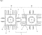
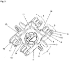
- the construction element (20) comprises two parallel base plates (4) and two parallel further base plates (7) forming together a square, wherein the two base plates (4) each comprise said male legs (3) as described above, applied symmetrically with respect to the middle of the base plate and wherein the two further base plates (7) each comprise a pair of female members (5) that extend at an extremity of the further base plate (7) in such a manner that one of the female legs (6) of said female member (5) extends in prolongation from an extremity of one of said base plates (4).
- the construction element (20) comprises one or more base plates (4), or one or more further base plates (7), or a combination thereof forming a closed area, wherein said base plates are connected by a connection plate (11) extending in a plane perpendicular to said base plates.
- This connection plate enhances the strength of the construction element and enables also to form complex three-dimensional structures, such as for example a container.
- the construction elements (20) comprise a connection plate (11) that connects the base plates (4) and/or the further base plates (7) and extends in a plane perpendicular to said base plates.
- said connection plate (11) connects the two base plates (4) and the two further base plates (7) of a construction element and extends in a plane perpendicular to said base plates.
- the construction element (20) preferably comprises a connection plate (11) connected to the base plates (4) and/or further base plates (7) and extending in a plane perpendicular to said base plates.
- said connection plate (11) comprises a ridge (12) at the connections between the connection plate (11) and the base plates (4) and further base plates (7).
- said ridge (12) comprises one or more openings (15); in particular one or more openings (15) at each of the connections between the connection plate (11) and the base plates (4) and/or further base plates (7).
- the base plates (4) and further base plates (7) of said construction element (20) comprise one or more protrusions (18); in particular at the side opposite to the side connected to the connection plate (11); more in particular at the side opposite to the side connected to the connection plate (11) and directly opposite to openings (15) at the ridge (12) of the connection plate (11).
- connection plate (11) in combination with the one or more openings (15) and one or more protrusions (18) at the side opposite to the side connected to the connection plate (11) ensure that multiple construction elements (20) are stackable to each other by clicking the ridge (12) of a first construction element into the base of the three-dimensional structure formed by the combination of the connection plate (11) with the base plates (4) and/or further base plates (7) (supra) of a second construction element, and so on.
- connection plate (11) comprises one or more apertures (13).
- connection plate (11) comprises four apertures (13), in particular located at the centre of the connection plate (11) and positioned two by two in an opposite position; more in particular positioned in a circular groove in the connection plate (11).
- the construction element (20) also comprises in one of its embodiments one or more cylindrical slits (14). More in particular, the base plate (4) and further base plate (7) of said construction element (20) comprise a cylindrical slit (14). Even more in particular, said cylindrical slit (14) of the base plate (4) is located in between the two parallel male legs (3) of the male member (2). In yet another embodiment, said cylindrical slit (14) of the further base plate (7) is located in between the two female members (5).
- the distance between the male legs (3) of the construction element (20) according to the present invention is equal to L
- the distance between the female legs (6) is equal to L
- the height of the legs is equal to L
- the length of the base plates (4) is equal to 3L
- the height of the base plates is equal to L.
- the present invention also provides a combination of two or more construction elements (20) according to anyone of the embodiments as described herein above; said combination comprising a hinge connection according to the invention, wherein the male member (2) of a first connection element (20) is resiliently fitted between a pair of female members (5) of a second construction element (20).
- the present invention also discloses the use of a hinge connection (1), a construction element (20), or a combination of two or more construction elements as described herein above as a building toy.
- the present invention further relates to a tool provided for disconnecting a connection of a female member (5) from a male member (2) of the hinge connection (1), wherein said tool comprises two spaced apart lever legs, each lever leg being provided for being positioned between said two female legs for tilting said female member out of said male member.
- the present invention is directed to a hinge connection and a construction element comprising said hinge connection.
- the present invention provides an improved and robust hinge connection that can be used in the construction of complex three-dimensional (3D) structures without loss of flexibility but with maintenance of stability.
- the hinge connection (1) comprises a male member (2) applied on a base plate (4) and a pair for female members (5) applied on a further base plate (7), wherein said male member (2) is fitted between a pair of female members (5) formed by two parallel female legs (6) on said further base plate (7).
- the male member (2) has protrusions (8) on each leg of the male member (2), wherein said protrusions (8) comprise cogs or cut teeth. These protrusions (8) are provided to have said male member (2) hinged and resiliently fitted between a pair of female members (5).
- each of the female members (5) comprises a through hole (10) wherein said through hole (10) comprises cogs or cut teeth to receive the protrusions (8), in particular the cogs or cut teeth of the male member (5).
- the two parallel legs (6) are connected by an intermediary piece (9) wherein said through hole (10) extends through said female legs (6) and said intermediary piece (9).
- said intermediary piece (9) and/or the female legs (6) of the female member (5) are interrupted.
- the intermediary piece (9) is interrupted in the transverse direction (17), as shown in Figures 1 and 2 .
- the intermediary piece (9) and both the female legs (6) are interrupted in the longitudinal direction (16).
- the intermediary piece (9) is interrupted in both the transverse direction (17) and the longitudinal direction (16) and the female legs (6) are interrupted in the longitudinal direction (16).
- the interruptions of both the intermediary piece (9) and the female legs (6) are of particular importance for the transfer of forces that are applied when creating the hinge connection (1). Even more in particular, since the interruptions (16, 17) are present in both directions, both longitudinal and transversal, the forces that are applied when creating the hinge connection are transferred in both these directions.
- the male member (2) is easily fitted between a pair of female members (5) thereby increasing the ease of use, without loss of stability of the hinge connection.
- the interruption of both the intermediary piece (9) and the female legs (6) thus facilitates the creation of the hinge connection (1). Without the presence of said interruptions, the intermediary piece (9) and the female legs (6) would be much more rigid, thereby impeding the positioning of the male member (2) in between the pair of female members (5).
- the male member (2) can be easily and transiently, though still rigidly, positioned in between said pair of female members (5), and it makes it easier to separate the hinge members when required.
- the male (2) and female (5) members are preferably provided with rounded free ends.
- the male (3) and female (6) legs comprise rounded borders. As a result of both the rounded free ends and the rounded borders, the hinge movement of the hinge connection is facilitated and the risk for injuries when creating complex structures with the construction elements is avoided. This is of particular importance when the construction elements are used as a toy.
- the present invention further discloses a construction element (20) comprising a hinge connection (1) as outlined herein above.
- the construction element (20) comprises at least one base plate (4) with at least one male member (2) as detailed herein above.
- the construction element (20) comprises at least one further base plate (7) with at least a pair of female members (5) as detailed herein above.
- the construction element (20) according to the present invention comprises at least one base plate (4) with at least one male member (2) and at least one further base plate (7) with at least a pair of female members (5).
- the construction element (20) of the present invention comprises at least base plates and/or further base plates forming a closed area.
- the construction element (20) according to the present invention comprises two parallel base plates (4) and two parallel further base plates (7) forming together a square.
- the two base plates (4) each comprise male legs (3) applied symmetrically with respect to the middle of the base plate (4) and wherein the two further base plates (7) each comprise a pair of female members (5) wherein each female member (5) extends at an extremity of the further base plate (7) in such a manner that one of the female legs (6) of said female member (5) extends in prolongation from an extremity of one of said base plates (4).
- the construction element (20) comprises 3 base plates (2) each comprising a male member (5) and 3 other base plates without any female or male member.
- typical for the hinge connection (1) is that it is established via the presence of protrusions (8).
- Said protrusions are present on each leg (3) of the male members (2) and allow the male member to be hinged and resiliently fitted into the gear protrusions of the female member (5).
- said protrusions on each leg of the male member comprise cogs or cut teeth. These cogs or cut teeth perfectly fit into the cogs or cut teeth of the through hole (10) of the female member (5). Because of the presence of said protrusions, in particular comprising cogs or cut teeth, an improved and robust hinge connection between two construction elements is provided that can be used in the construction of complex three-dimensional structures without loss of flexibility.
- the fitting of the cogs or cut teeth of the male protrusions into the cogs or cut teeth of the female member (5) allows adjacent construction elements to be positioned in several different angles relative to each other.
- the 3D structure becomes more rigid, and its shape is at least partially constrained and dependent upon the choice of the fixed relative angle between any two adjacent elements included in the multi-panel structure.
- the relative angle between two construction elements according to the present invention is fixed at up to 11 discrete angles: 90°, 108°, 126°, 144°, 162°, 180°, 198°, 216°, 234°, 252°, and 270°.
- the ability to fix the relative angle between each pair of coupled construction elements enables a user to construct 3D structures of significant diversity in both shape and form. With 11 possible angle choices between each pair of coupled construction elements, the shape of the possible 3D structures is practically unlimited.
- the construction element comprising at least one further base plate (7) with at least a pair of female member (5), further comprises two linking members (21) applied on a base plate and provided to be resiliently fitted on two female members.
- Said female members are formed by two parallel female legs and comprise a through hole and wherein the two parallel female legs are connected by an intermediary piece and wherein said through hole extends through said female legs and said intermediary piece.
- the linking members (21) of said construction element are characterized in that they comprise a C-shaped curved leg (22). As a result, the C-shaped curved legs (22) of the linking members (21) resiliently fit onto the female members of a second construction element.
- the construction element according to the present invention comprises a connection plate (11) that connects the base plates (4) and/or the further base plates (7) and extends in a plane perpendicular to said base plates.
- Said connection plate (11) enhances the strength of the construction element and enables to form a container for receiving all kind of objects or goods, for example sweets.
- the formed container may also be used as packaging.
- the connection plate (11) connects two base plates (4) and two further base plates (7) and extends in a plane perpendicular to said base plates.
- connection plate (11) of the construction element (20) comprises a ridge (12) at the connections between the connection plate (11) and the base plates (4) and further base plates (7).
- said ridge (12) comprises one or more openings (15); in particular one or more openings at each of the connections between the connection plate (11) and the base plates (4) and further base plates (7).
- the base plates (4) and further base plates (7) of said construction element (20) comprise one or more protrusions (18); in particular at the side opposite to the side connected to the connection plate (11); more in particular at the side opposite to the side connected to the connection plate (11) and directly opposite to openings (15) at the ridge (12) of the connection plate (11).
- connection plate (11) in combination with the one or more openings (15) and one or more protrusions (18) at the side opposite to the side connected to the connection plate (11) ensure that multiple construction elements (20) are stackable to each other by clicking the ridge (12) of a first construction element into the base of the three-dimensional structure formed by the combination of the connection plate (11) with the base plates (4) and/or further base plates (7) of a second construction element, and so on.
- the protrusions (18) on the base plates (4) and/or further base plates (7) fit in the openings (15) at the ridge (12) of the connection plate (11).
- the distance between the female legs (6) is equal to L
- the distance between the male legs (3) is equal to L
- the height of the legs is equal to L
- the length of the base plate (4) and the further base plate (7) is equal to 3L and the height of the base plate (4) and the further base plate (7) is equal to L.
- the hinge connection and connection elements of the present invention are advantageously made from a material that allows repeated deflections to occur, without permanent deformation thereof. Thickness of the connection elements is chosen so as to obtain similar results. Or expressed differently, the hinge connection as detailed herein above and the construction element comprising said hinge connection are produced in a robust but still flexible material.
- said hinge connection and construction element are produced in a plastic material, for example polypropylene or acrylonitrile butadiene styrene (ABS). in a preferred embodiment, the hinge connection and construction element comprising said hinge connection are produced in ABS.
- the present invention is also related to a combination of two or more construction elements (20) as described herein above.
- Said combination comprises a hinge connection according to the present invention, wherein the male member (2) of a first construction element (20) is resiliently fitted between a pair of female members (5) of a second construction element (20).
- the present invention is further related to the use of a hinge connection, a construction element, or a combination of two or more construction elements (20) as outlined herein above as a building toy.
- said hinge connection and construction element may be used as a toy and enable to create complex structures wherein planning and use of imagination is required. This contributes to the development of a child playing with those construction elements.
- the 3D structures that can be made when combining different construction elements of the present invention are formed by building up geometric shapes that include angles not limited to right angles.
- Such 3D structures may include, but are not limited to various forms of forts, castles, houses, furniture and toy vehicles.
- the preferred embodiments include the construction of toy-like structures, other embodiments are not so constrained.
- these more particular constructions may include, but are otherwise not limited to furniture, temporary housing units, modular shelters, and mobile military, medical, or emergency facilities.
- the present invention also provides a tool for disconnecting a connection of a female member (5) from a male member (2) of the hinge connection (1).
- Said tool comprises two spaced apart lever legs, each lever leg being provided for being positioned between said two female legs for tilting said female member out of said male member.
Landscapes
- Health & Medical Sciences (AREA)
- Engineering & Computer Science (AREA)
- Biomedical Technology (AREA)
- Neurology (AREA)
- Orthopedic Medicine & Surgery (AREA)
- Epidemiology (AREA)
- Pain & Pain Management (AREA)
- Physical Education & Sports Medicine (AREA)
- Rehabilitation Therapy (AREA)
- Life Sciences & Earth Sciences (AREA)
- Animal Behavior & Ethology (AREA)
- General Health & Medical Sciences (AREA)
- Public Health (AREA)
- Veterinary Medicine (AREA)
- Toys (AREA)
Claims (13)
- Eine Scharnierverbindung (1), umfassend ein auf einer Grundplatte (4) aufgebrachtes Steckglied (2) und ein Paar auf einer weiteren Grundplatte (7) aufgebrachte Aufnahmeglieder (5), wobei das Steckglied Überstände (8) aufweist und bereitgestellt ist, um zwischen einem Paar auf der weiteren Grundplatte (7) aufgebrachten Aufnahmegliedern (5) eingehängt und elastisch montiert zu sein, wobei das Steckglied (2) aus zwei parallelen Steckschenkeln (3) gebildet ist, wobei jeder Schenkel einen der Überstände (8) umfasst, jedes der Aufnahmeglieder (5) aus zwei parallelen Aufnahmeschenkeln (6) gebildet ist und ein Durchgangsloch (10) zur Aufnahme eines der Überstände (8) umfasst, wobei die beiden parallelen Aufnahmeglieder (6) ein Zwischenstück (9) umfassen und wobei das Durchgangsloch (10) sich durch die Aufnahmeschenkel (6) und das Zwischenstück (9) erstreckt,
dadurch gekennzeichnet, dass- die Überstände (8) an jedem Schenkel des Steckglieds Zahnräder oder Verzahnungen umfassen,- das Durchgangsloch (10) des Aufnahmeglieds Zahnräder oder Verzahnungen umfasst, um die Zahnräder oder Verzahnungen der Stecküberstände (8) aufzunehmen, und- das Zwischenstück (9) der Aufnahmeglieder in der Querrichtung (17) senkrecht zur Mittelachse des Durchgangslochs (10) unterbrochen ist. - Scharnierverbindung (1) nach Patentanspruch 1, wobei das Zwischenstück (9) und die Aufnahmeschenkel des Aufnahmeglieds in der Längsrichtung (16) unterbrochen sind.
- Konstruktionselement (20), umfassend mindestens eine Grundplatte (4) mit mindestens einem Steckglied (2) und mindestens einer weiteren Grundplatte (7) mit mindestens einem Paar von Aufnahmegliedern (5), wobei das Steckglied Überstände (8) aufweist und bereitgestellt ist, um zwischen einem Paar auf der weiteren Grundplatte (7) aufgebrachten Aufnahmeglieder (5) eingehängt und elastisch montiert zu sein, wobei das Steckglied (2) aus zwei parallelen Steckschenkeln (3) gebildet ist, wobei jeder Schenkel einen der Überstände (8) umfasst, jedes der Aufnahmeglieder (5) aus zwei parallelen Aufnahmeschenkeln (6) gebildet ist und ein Durchgangsloch (10) zur Aufnahme eines der Überstände (8) umfasst, wobei die zwei parallelen Aufnahmeglieder (6) ein Zwischenstück (9) umfassen und wobei das Durchgangsloch (10) sich durch die Aufnahmeschenkel (6) und das Zwischenstück (9) erstreckt,
dadurch gekennzeichnet, dass- die Überstände (8) an jedem Schenkel des Steckglieds Zahnräder oder Verzahnungen umfassen,- das Durchgangsloch (10) des Aufnahmeglieds Zahnräder oder Verzahnungen umfasst, um die Zahnräder oder Verzahnungen der Stecküberstände (8) aufzunehmen, und- das Zwischenstück (9) der Aufnahmeglieder in der Querrichtung (17) senkrecht zur Mittelachse des Durchgangslochs (10) unterbrochen ist. - Konstruktionselement (20) nach Patentanspruch 3, umfassend zwei parallele Grundplatten (4) und zwei parallele weitere Grundplatten (7), die zusammen ein Quadrat bilden, wobei die zwei Grundplatten (4) jeweils das gegenüber der Mitte der Grundplatte (4) symmetrisch aufgebrachte Steckglied (2) umfassen und wobei die beiden weiteren Grundplatten (7) jeweils ein Paar der Aufnahmeglieder (5) umfassen, wobei sich jedes Aufnahmeglied (5) des Paares an einem Ende der weiteren Grundplatte (7) so erstreckt, dass sich einer der Aufnahmeschenkel (6) des Aufnahmegliedes (5) in Verlängerung von einem Ende einer der der Grundplatten (4) erstreckt.
- Satz von Konstruktionselementen, die das Konstruktionselement nach Patentanspruch 3 umfassen und ein weiteres Konstruktionselement (20) mit zwei Verbindungsgliedern (21) umfassen, die auf einer Grundplatte aufgebracht sind, die für eine elastische Montage auf zwei Aufnahmegliedern (5) bereitgestellt sind, dadurch gekennzeichnet, dass das Verbindungsglied (21) einen C-förmig gebogenen Schenkel (22) umfasst.
- Konstruktionselement (20) nach einem der Patentansprüche 3 bis 4, umfassend eine Verbindungsplatte (11), die die Grundplatten (4) und/oder die weiteren Grundplatten (7) verbindet und sich in einer Ebene senkrecht zu den Grundplatten erstreckt.
- Konstruktionselement (20) nach Patentanspruch 6, wobei die Verbindungsplatte (11) eine Kante (12) an den Verbindungen zwischen der Verbindungsplatte (11) und den Grundplatten (4) und weiteren Grundplatten (7) umfasst.
- Konstruktionselement (20) nach Patentanspruch 7, wobei die Kante (12) eine oder mehrere Öffnungen (15) umfasst; insbesondere eine oder mehrere Öffnungen an jeder der Verbindungen zwischen der Verbindungsplatte (11) und den Grundplatten (4) und weiteren Grundplatten (7).
- Konstruktionselement (20) nach Patentanspruch 8, wobei die Grundplatten (4) und weiteren Grundplatten (7) einen oder mehrere Überstände (18) aufweisen; besonders an der der mit der Verbindungsplatte verbundenen Seite gegenüberliegenden Seite; insbesondere an der der mit der Verbindungsplatte verbundenen Seite gegenüberliegenden Seite und unmittelbar gegenüber von Öffnungen (15) an der Kante (12) der Verbindungsplatte (11).
- Konstruktionselement (20) nach einem der Patentansprüche 6 bis 9, wobei die Verbindungsplatte (11) eine oder mehrere Öffnungen (13) umfasst; insbesondere vier Öffnungen (13), die sich insbesondere in der Mitte der Verbindungsplatte befinden und zwei mal zwei in einer entgegengesetzten Position angeordnet sind; insbesondere in einer kreisförmigen Nut in der Verbindungsplatte angeordnet sind.
- Konstruktionselement (20) nach einem der Patentansprüche 3 bis 4 oder 6 bis 10, wobei der Abstand zwischen den Aufnahmeschenkeln gleich L ist, der Abstand zwischen den Steckschenkeln gleich L ist, die Höhe der Schenkel gleich L ist, die Länge der Grundplatte und der weiteren Grundplatte gleich 3L ist und die Höhe der Grundplatten gleich L ist.
- Kombination von zwei oder mehr Konstruktionselementen (20) nach einem der Patentansprüche 3 bis 4 oder 6 bis 11, wobei das Steckglied (2) eines ersten Konstruktionselements (20) elastisch zwischen einem Paar von Aufnahmegliedern (5) eines zweiten Konstruktionselements (20) angebracht ist.
- Verwendung einer Scharnierverbindung nach einem der Patentansprüche 1 oder 2 oder eines Konstruktionselements nach einem der Patentansprüche 3 bis 4 oder 6 bis 11 oder eines Satzes von Konstruktionselementen nach Patentanspruch 5 oder einer Kombination von zwei oder mehr Konstruktionselementen (20) nach Patentanspruch 12 als Konstruktionsspielzeug.
Applications Claiming Priority (2)
| Application Number | Priority Date | Filing Date | Title |
|---|---|---|---|
| EP16197761 | 2016-11-08 | ||
| PCT/EP2017/078642 WO2018087166A1 (en) | 2016-11-08 | 2017-11-08 | Stackable hinge connection |
Publications (2)
| Publication Number | Publication Date |
|---|---|
| EP3538236A1 EP3538236A1 (de) | 2019-09-18 |
| EP3538236B1 true EP3538236B1 (de) | 2021-03-03 |
Family
ID=57281057
Family Applications (1)
| Application Number | Title | Priority Date | Filing Date |
|---|---|---|---|
| EP17794745.4A Not-in-force EP3538236B1 (de) | 2016-11-08 | 2017-11-08 | Stapelbare scharnierverbindung |
Country Status (6)
| Country | Link |
|---|---|
| US (1) | US20190321741A1 (de) |
| EP (1) | EP3538236B1 (de) |
| KR (1) | KR20190095276A (de) |
| CN (1) | CN110139695A (de) |
| IL (1) | IL266491A (de) |
| WO (1) | WO2018087166A1 (de) |
Families Citing this family (6)
| Publication number | Priority date | Publication date | Assignee | Title |
|---|---|---|---|---|
| US11278822B2 (en) * | 2019-08-28 | 2022-03-22 | Huntar Company | Toy construction block kit |
| CN110694284B (zh) * | 2019-09-23 | 2021-12-31 | 深圳市优必选科技股份有限公司 | 积木玩具及其连接组件 |
| CN213100839U (zh) * | 2020-10-21 | 2021-05-04 | 东莞市九畅智能科技有限公司 | 一种拆装简易的积木 |
| US11358071B1 (en) * | 2020-12-30 | 2022-06-14 | Gracewood Management, Inc. | Building block toy |
| US20240408507A1 (en) * | 2021-10-04 | 2024-12-12 | Combine-It Bv | Assembly system for 3d shapes with beads |
| US11746579B1 (en) * | 2022-04-08 | 2023-09-05 | The Boeing Company | Hinge assembly and stackable hinge assembly for rotation about an opening |
Family Cites Families (17)
| Publication number | Priority date | Publication date | Assignee | Title |
|---|---|---|---|---|
| DE2636990A1 (de) * | 1976-08-17 | 1978-02-23 | Verner Panton | Bausatz, insbesondere spielzeugbausatz |
| CA1222869A (en) * | 1983-03-30 | 1987-06-16 | 284215 Alberta Limited | Connectable polygonal construction modules |
| DK154391D0 (da) * | 1991-09-03 | 1991-09-03 | Gram Ole As | Byggeelement isaer til legetoej |
| BE1010833A6 (nl) * | 1997-01-06 | 1999-02-02 | Parein Eric | Speelgoedelement. |
| US5853314A (en) * | 1997-02-18 | 1998-12-29 | Bora; Sunil K. | Toy building block |
| TW508040U (en) * | 2001-09-05 | 2002-10-21 | Hinge Basestrong Co Ltd | Radial pressing structure of rotation shaft |
| US6648715B2 (en) * | 2001-10-25 | 2003-11-18 | Benjamin I. Wiens | Snap-fit construction system |
| EP2089589A1 (de) * | 2006-11-20 | 2009-08-19 | Les Jouets Brik-A-Blok Inc./Brik-A-Blok Toys Inc. | Verriegelungsplatten und ausrüstung aus solchen platten |
| GB2445786A (en) * | 2007-01-16 | 2008-07-23 | Timothy John Warner | Blocks for making model structures |
| CN201020293Y (zh) * | 2007-04-28 | 2008-02-13 | 陈忠伟 | 一种拼接玩具 |
| TWM415736U (en) * | 2010-12-31 | 2011-11-11 | Genius Toy Taiwan Co Ltd | Transitional building blocks group |
| WO2013138336A1 (en) * | 2012-03-12 | 2013-09-19 | Reell Precision Manufacturing Corporation | Circumferential strain rotary detent |
| KR101575095B1 (ko) * | 2013-02-15 | 2015-12-08 | 김승남 | 조립식 완구 |
| CN204050991U (zh) * | 2014-09-03 | 2014-12-31 | 浙江大森林工艺品有限公司 | 一种百变扣扣基础套件组合玩具 |
| CN104258578B (zh) * | 2014-10-28 | 2016-09-14 | 陶宇晨 | 一种拼接玩具 |
| CN204910781U (zh) * | 2015-08-18 | 2015-12-30 | 上海华森葳教育用品有限公司 | 益智卡接连接片 |
| CN204910786U (zh) * | 2015-08-18 | 2015-12-30 | 上海华森葳教育用品有限公司 | 益智卡接连接片 |
-
2017
- 2017-11-08 US US16/348,227 patent/US20190321741A1/en not_active Abandoned
- 2017-11-08 KR KR1020197016107A patent/KR20190095276A/ko not_active Withdrawn
- 2017-11-08 EP EP17794745.4A patent/EP3538236B1/de not_active Not-in-force
- 2017-11-08 WO PCT/EP2017/078642 patent/WO2018087166A1/en not_active Ceased
- 2017-11-08 CN CN201780081900.5A patent/CN110139695A/zh active Pending
-
2019
- 2019-05-06 IL IL266491A patent/IL266491A/en unknown
Non-Patent Citations (1)
| Title |
|---|
| None * |
Also Published As
| Publication number | Publication date |
|---|---|
| IL266491A (en) | 2019-07-31 |
| WO2018087166A1 (en) | 2018-05-17 |
| EP3538236A1 (de) | 2019-09-18 |
| KR20190095276A (ko) | 2019-08-14 |
| US20190321741A1 (en) | 2019-10-24 |
| CN110139695A (zh) | 2019-08-16 |
Similar Documents
| Publication | Publication Date | Title |
|---|---|---|
| EP3538236B1 (de) | Stapelbare scharnierverbindung | |
| EP3319700B1 (de) | Spielzeugbaukasten | |
| US9004799B1 (en) | Transformable linked self-assembly system | |
| US7347028B1 (en) | Modular construction system utilizing versatile construction elements with multi-directional connective surfaces and releasable interconnect elements | |
| JP3221413U (ja) | 左右ローリングで弾性作用されて結合を容易にしながら摩耗を防止したチェーンブロック玩具 | |
| KR101079505B1 (ko) | 유아용 블록완구 | |
| EP1112768A2 (de) | Paneele und Träger für miteinander verbundene Spielbausteine | |
| KR102539859B1 (ko) | 3차원 구조 생성을 위한 구축 시스템 | |
| US5725411A (en) | Construction beam block toy with selective angular interlock | |
| US10286332B2 (en) | Toy construction set with articulating linkable elements | |
| US6948998B2 (en) | Interconnectable model construction elements | |
| WO2015168223A1 (en) | Toy construction set | |
| US3660928A (en) | Modular building blocks with interfitting grooved surfaces | |
| US5908342A (en) | Three dimensional connector | |
| KR20170065212A (ko) | 탄성벽을 이용한 체결구조를 가지는 디오라마 조립식 블록 | |
| JP6466909B2 (ja) | 組立キット | |
| KR200469966Y1 (ko) | 조립식 블록 완구 | |
| US3777393A (en) | Construction toy | |
| JP6005711B2 (ja) | 組立構造体 | |
| CA3056012C (en) | Toy construction set with articulating linkable elements | |
| KR20150100572A (ko) | 구성형 장난감 | |
| JP2017006605A (ja) | 組立ブロックおもちゃ用ジョイント | |
| CN204601629U (zh) | 一种可拆卸模块化构件、固定件、活动件及连接组合结构 | |
| KR200461024Y1 (ko) | 조립식 블록완구용 회전연결블록 | |
| EP2656890A1 (de) | Kupplungssystem für Module |
Legal Events
| Date | Code | Title | Description |
|---|---|---|---|
| STAA | Information on the status of an ep patent application or granted ep patent |
Free format text: STATUS: UNKNOWN |
|
| STAA | Information on the status of an ep patent application or granted ep patent |
Free format text: STATUS: THE INTERNATIONAL PUBLICATION HAS BEEN MADE |
|
| PUAI | Public reference made under article 153(3) epc to a published international application that has entered the european phase |
Free format text: ORIGINAL CODE: 0009012 |
|
| STAA | Information on the status of an ep patent application or granted ep patent |
Free format text: STATUS: REQUEST FOR EXAMINATION WAS MADE |
|
| 17P | Request for examination filed |
Effective date: 20190603 |
|
| AK | Designated contracting states |
Kind code of ref document: A1 Designated state(s): AL AT BE BG CH CY CZ DE DK EE ES FI FR GB GR HR HU IE IS IT LI LT LU LV MC MK MT NL NO PL PT RO RS SE SI SK SM TR |
|
| AX | Request for extension of the european patent |
Extension state: BA ME |
|
| DAV | Request for validation of the european patent (deleted) | ||
| DAX | Request for extension of the european patent (deleted) | ||
| REG | Reference to a national code |
Ref country code: DE Ref legal event code: R079 Ref document number: 602017033936 Country of ref document: DE Free format text: PREVIOUS MAIN CLASS: A63H0033080000 Ipc: A61H0001020000 |
|
| RIC1 | Information provided on ipc code assigned before grant |
Ipc: A61H 1/02 20060101AFI20200707BHEP |
|
| GRAP | Despatch of communication of intention to grant a patent |
Free format text: ORIGINAL CODE: EPIDOSNIGR1 |
|
| STAA | Information on the status of an ep patent application or granted ep patent |
Free format text: STATUS: GRANT OF PATENT IS INTENDED |
|
| INTG | Intention to grant announced |
Effective date: 20200928 |
|
| GRAS | Grant fee paid |
Free format text: ORIGINAL CODE: EPIDOSNIGR3 |
|
| GRAA | (expected) grant |
Free format text: ORIGINAL CODE: 0009210 |
|
| STAA | Information on the status of an ep patent application or granted ep patent |
Free format text: STATUS: THE PATENT HAS BEEN GRANTED |
|
| AK | Designated contracting states |
Kind code of ref document: B1 Designated state(s): AL AT BE BG CH CY CZ DE DK EE ES FI FR GB GR HR HU IE IS IT LI LT LU LV MC MK MT NL NO PL PT RO RS SE SI SK SM TR |
|
| REG | Reference to a national code |
Ref country code: GB Ref legal event code: FG4D |
|
| REG | Reference to a national code |
Ref country code: CH Ref legal event code: EP Ref country code: AT Ref legal event code: REF Ref document number: 1366409 Country of ref document: AT Kind code of ref document: T Effective date: 20210315 |
|
| REG | Reference to a national code |
Ref country code: DE Ref legal event code: R096 Ref document number: 602017033936 Country of ref document: DE |
|
| REG | Reference to a national code |
Ref country code: IE Ref legal event code: FG4D |
|
| REG | Reference to a national code |
Ref country code: NL Ref legal event code: FP |
|
| REG | Reference to a national code |
Ref country code: LT Ref legal event code: MG9D |
|
| PG25 | Lapsed in a contracting state [announced via postgrant information from national office to epo] |
Ref country code: BG Free format text: LAPSE BECAUSE OF FAILURE TO SUBMIT A TRANSLATION OF THE DESCRIPTION OR TO PAY THE FEE WITHIN THE PRESCRIBED TIME-LIMIT Effective date: 20210603 Ref country code: LT Free format text: LAPSE BECAUSE OF FAILURE TO SUBMIT A TRANSLATION OF THE DESCRIPTION OR TO PAY THE FEE WITHIN THE PRESCRIBED TIME-LIMIT Effective date: 20210303 Ref country code: GR Free format text: LAPSE BECAUSE OF FAILURE TO SUBMIT A TRANSLATION OF THE DESCRIPTION OR TO PAY THE FEE WITHIN THE PRESCRIBED TIME-LIMIT Effective date: 20210604 Ref country code: HR Free format text: LAPSE BECAUSE OF FAILURE TO SUBMIT A TRANSLATION OF THE DESCRIPTION OR TO PAY THE FEE WITHIN THE PRESCRIBED TIME-LIMIT Effective date: 20210303 Ref country code: FI Free format text: LAPSE BECAUSE OF FAILURE TO SUBMIT A TRANSLATION OF THE DESCRIPTION OR TO PAY THE FEE WITHIN THE PRESCRIBED TIME-LIMIT Effective date: 20210303 Ref country code: NO Free format text: LAPSE BECAUSE OF FAILURE TO SUBMIT A TRANSLATION OF THE DESCRIPTION OR TO PAY THE FEE WITHIN THE PRESCRIBED TIME-LIMIT Effective date: 20210603 |
|
| REG | Reference to a national code |
Ref country code: AT Ref legal event code: MK05 Ref document number: 1366409 Country of ref document: AT Kind code of ref document: T Effective date: 20210303 |
|
| PG25 | Lapsed in a contracting state [announced via postgrant information from national office to epo] |
Ref country code: SE Free format text: LAPSE BECAUSE OF FAILURE TO SUBMIT A TRANSLATION OF THE DESCRIPTION OR TO PAY THE FEE WITHIN THE PRESCRIBED TIME-LIMIT Effective date: 20210303 Ref country code: RS Free format text: LAPSE BECAUSE OF FAILURE TO SUBMIT A TRANSLATION OF THE DESCRIPTION OR TO PAY THE FEE WITHIN THE PRESCRIBED TIME-LIMIT Effective date: 20210303 Ref country code: PL Free format text: LAPSE BECAUSE OF FAILURE TO SUBMIT A TRANSLATION OF THE DESCRIPTION OR TO PAY THE FEE WITHIN THE PRESCRIBED TIME-LIMIT Effective date: 20210303 Ref country code: LV Free format text: LAPSE BECAUSE OF FAILURE TO SUBMIT A TRANSLATION OF THE DESCRIPTION OR TO PAY THE FEE WITHIN THE PRESCRIBED TIME-LIMIT Effective date: 20210303 |
|
| PG25 | Lapsed in a contracting state [announced via postgrant information from national office to epo] |
Ref country code: SM Free format text: LAPSE BECAUSE OF FAILURE TO SUBMIT A TRANSLATION OF THE DESCRIPTION OR TO PAY THE FEE WITHIN THE PRESCRIBED TIME-LIMIT Effective date: 20210303 Ref country code: AT Free format text: LAPSE BECAUSE OF FAILURE TO SUBMIT A TRANSLATION OF THE DESCRIPTION OR TO PAY THE FEE WITHIN THE PRESCRIBED TIME-LIMIT Effective date: 20210303 Ref country code: CZ Free format text: LAPSE BECAUSE OF FAILURE TO SUBMIT A TRANSLATION OF THE DESCRIPTION OR TO PAY THE FEE WITHIN THE PRESCRIBED TIME-LIMIT Effective date: 20210303 Ref country code: EE Free format text: LAPSE BECAUSE OF FAILURE TO SUBMIT A TRANSLATION OF THE DESCRIPTION OR TO PAY THE FEE WITHIN THE PRESCRIBED TIME-LIMIT Effective date: 20210303 |
|
| PG25 | Lapsed in a contracting state [announced via postgrant information from national office to epo] |
Ref country code: IS Free format text: LAPSE BECAUSE OF FAILURE TO SUBMIT A TRANSLATION OF THE DESCRIPTION OR TO PAY THE FEE WITHIN THE PRESCRIBED TIME-LIMIT Effective date: 20210703 Ref country code: PT Free format text: LAPSE BECAUSE OF FAILURE TO SUBMIT A TRANSLATION OF THE DESCRIPTION OR TO PAY THE FEE WITHIN THE PRESCRIBED TIME-LIMIT Effective date: 20210705 Ref country code: RO Free format text: LAPSE BECAUSE OF FAILURE TO SUBMIT A TRANSLATION OF THE DESCRIPTION OR TO PAY THE FEE WITHIN THE PRESCRIBED TIME-LIMIT Effective date: 20210303 Ref country code: SK Free format text: LAPSE BECAUSE OF FAILURE TO SUBMIT A TRANSLATION OF THE DESCRIPTION OR TO PAY THE FEE WITHIN THE PRESCRIBED TIME-LIMIT Effective date: 20210303 |
|
| REG | Reference to a national code |
Ref country code: DE Ref legal event code: R097 Ref document number: 602017033936 Country of ref document: DE |
|
| PLBE | No opposition filed within time limit |
Free format text: ORIGINAL CODE: 0009261 |
|
| STAA | Information on the status of an ep patent application or granted ep patent |
Free format text: STATUS: NO OPPOSITION FILED WITHIN TIME LIMIT |
|
| PG25 | Lapsed in a contracting state [announced via postgrant information from national office to epo] |
Ref country code: DK Free format text: LAPSE BECAUSE OF FAILURE TO SUBMIT A TRANSLATION OF THE DESCRIPTION OR TO PAY THE FEE WITHIN THE PRESCRIBED TIME-LIMIT Effective date: 20210303 Ref country code: AL Free format text: LAPSE BECAUSE OF FAILURE TO SUBMIT A TRANSLATION OF THE DESCRIPTION OR TO PAY THE FEE WITHIN THE PRESCRIBED TIME-LIMIT Effective date: 20210303 Ref country code: ES Free format text: LAPSE BECAUSE OF FAILURE TO SUBMIT A TRANSLATION OF THE DESCRIPTION OR TO PAY THE FEE WITHIN THE PRESCRIBED TIME-LIMIT Effective date: 20210303 |
|
| PGFP | Annual fee paid to national office [announced via postgrant information from national office to epo] |
Ref country code: NL Payment date: 20211118 Year of fee payment: 5 Ref country code: DE Payment date: 20211118 Year of fee payment: 5 Ref country code: FR Payment date: 20211119 Year of fee payment: 5 |
|
| 26N | No opposition filed |
Effective date: 20211206 |
|
| PG25 | Lapsed in a contracting state [announced via postgrant information from national office to epo] |
Ref country code: SI Free format text: LAPSE BECAUSE OF FAILURE TO SUBMIT A TRANSLATION OF THE DESCRIPTION OR TO PAY THE FEE WITHIN THE PRESCRIBED TIME-LIMIT Effective date: 20210303 |
|
| PGFP | Annual fee paid to national office [announced via postgrant information from national office to epo] |
Ref country code: BE Payment date: 20211118 Year of fee payment: 5 |
|
| PG25 | Lapsed in a contracting state [announced via postgrant information from national office to epo] |
Ref country code: IT Free format text: LAPSE BECAUSE OF FAILURE TO SUBMIT A TRANSLATION OF THE DESCRIPTION OR TO PAY THE FEE WITHIN THE PRESCRIBED TIME-LIMIT Effective date: 20210303 |
|
| PG25 | Lapsed in a contracting state [announced via postgrant information from national office to epo] |
Ref country code: IS Free format text: LAPSE BECAUSE OF FAILURE TO SUBMIT A TRANSLATION OF THE DESCRIPTION OR TO PAY THE FEE WITHIN THE PRESCRIBED TIME-LIMIT Effective date: 20210703 |
|
| PG25 | Lapsed in a contracting state [announced via postgrant information from national office to epo] |
Ref country code: MC Free format text: LAPSE BECAUSE OF FAILURE TO SUBMIT A TRANSLATION OF THE DESCRIPTION OR TO PAY THE FEE WITHIN THE PRESCRIBED TIME-LIMIT Effective date: 20210303 |
|
| REG | Reference to a national code |
Ref country code: CH Ref legal event code: PL |
|
| GBPC | Gb: european patent ceased through non-payment of renewal fee |
Effective date: 20211108 |
|
| PG25 | Lapsed in a contracting state [announced via postgrant information from national office to epo] |
Ref country code: LU Free format text: LAPSE BECAUSE OF NON-PAYMENT OF DUE FEES Effective date: 20211108 |
|
| PG25 | Lapsed in a contracting state [announced via postgrant information from national office to epo] |
Ref country code: LI Free format text: LAPSE BECAUSE OF NON-PAYMENT OF DUE FEES Effective date: 20211130 Ref country code: CH Free format text: LAPSE BECAUSE OF NON-PAYMENT OF DUE FEES Effective date: 20211130 |
|
| PG25 | Lapsed in a contracting state [announced via postgrant information from national office to epo] |
Ref country code: IE Free format text: LAPSE BECAUSE OF NON-PAYMENT OF DUE FEES Effective date: 20211108 Ref country code: GB Free format text: LAPSE BECAUSE OF NON-PAYMENT OF DUE FEES Effective date: 20211108 |
|
| REG | Reference to a national code |
Ref country code: DE Ref legal event code: R119 Ref document number: 602017033936 Country of ref document: DE |
|
| PG25 | Lapsed in a contracting state [announced via postgrant information from national office to epo] |
Ref country code: CY Free format text: LAPSE BECAUSE OF FAILURE TO SUBMIT A TRANSLATION OF THE DESCRIPTION OR TO PAY THE FEE WITHIN THE PRESCRIBED TIME-LIMIT Effective date: 20210303 |
|
| REG | Reference to a national code |
Ref country code: NL Ref legal event code: MM Effective date: 20221201 |
|
| REG | Reference to a national code |
Ref country code: BE Ref legal event code: MM Effective date: 20221130 |
|
| PG25 | Lapsed in a contracting state [announced via postgrant information from national office to epo] |
Ref country code: HU Free format text: LAPSE BECAUSE OF FAILURE TO SUBMIT A TRANSLATION OF THE DESCRIPTION OR TO PAY THE FEE WITHIN THE PRESCRIBED TIME-LIMIT; INVALID AB INITIO Effective date: 20171108 |
|
| PG25 | Lapsed in a contracting state [announced via postgrant information from national office to epo] |
Ref country code: NL Free format text: LAPSE BECAUSE OF NON-PAYMENT OF DUE FEES Effective date: 20221201 |
|
| PG25 | Lapsed in a contracting state [announced via postgrant information from national office to epo] |
Ref country code: DE Free format text: LAPSE BECAUSE OF NON-PAYMENT OF DUE FEES Effective date: 20230601 |
|
| PG25 | Lapsed in a contracting state [announced via postgrant information from national office to epo] |
Ref country code: FR Free format text: LAPSE BECAUSE OF NON-PAYMENT OF DUE FEES Effective date: 20221130 Ref country code: BE Free format text: LAPSE BECAUSE OF NON-PAYMENT OF DUE FEES Effective date: 20221130 |
|
| PG25 | Lapsed in a contracting state [announced via postgrant information from national office to epo] |
Ref country code: MK Free format text: LAPSE BECAUSE OF FAILURE TO SUBMIT A TRANSLATION OF THE DESCRIPTION OR TO PAY THE FEE WITHIN THE PRESCRIBED TIME-LIMIT Effective date: 20210303 |
|
| PG25 | Lapsed in a contracting state [announced via postgrant information from national office to epo] |
Ref country code: TR Free format text: LAPSE BECAUSE OF FAILURE TO SUBMIT A TRANSLATION OF THE DESCRIPTION OR TO PAY THE FEE WITHIN THE PRESCRIBED TIME-LIMIT Effective date: 20210303 |
|
| PG25 | Lapsed in a contracting state [announced via postgrant information from national office to epo] |
Ref country code: MT Free format text: LAPSE BECAUSE OF FAILURE TO SUBMIT A TRANSLATION OF THE DESCRIPTION OR TO PAY THE FEE WITHIN THE PRESCRIBED TIME-LIMIT Effective date: 20210303 |