EP3538313B1 - Verfahren zum magnetimpulsschweissen eines blechstapels - Google Patents
Verfahren zum magnetimpulsschweissen eines blechstapels Download PDFInfo
- Publication number
- EP3538313B1 EP3538313B1 EP17801411.4A EP17801411A EP3538313B1 EP 3538313 B1 EP3538313 B1 EP 3538313B1 EP 17801411 A EP17801411 A EP 17801411A EP 3538313 B1 EP3538313 B1 EP 3538313B1
- Authority
- EP
- European Patent Office
- Prior art keywords
- perforation
- stack
- plate
- plates
- perforations
- Prior art date
- Legal status (The legal status is an assumption and is not a legal conclusion. Google has not performed a legal analysis and makes no representation as to the accuracy of the status listed.)
- Active
Links
Images

Classifications
-
- B—PERFORMING OPERATIONS; TRANSPORTING
- B23—MACHINE TOOLS; METAL-WORKING NOT OTHERWISE PROVIDED FOR
- B23K—SOLDERING OR UNSOLDERING; WELDING; CLADDING OR PLATING BY SOLDERING OR WELDING; CUTTING BY APPLYING HEAT LOCALLY, e.g. FLAME CUTTING; WORKING BY LASER BEAM
- B23K20/00—Non-electric welding by applying impact or other pressure, with or without the application of heat, e.g. cladding or plating
- B23K20/06—Non-electric welding by applying impact or other pressure, with or without the application of heat, e.g. cladding or plating by means of high energy impulses, e.g. magnetic energy
-
- B—PERFORMING OPERATIONS; TRANSPORTING
- B23—MACHINE TOOLS; METAL-WORKING NOT OTHERWISE PROVIDED FOR
- B23K—SOLDERING OR UNSOLDERING; WELDING; CLADDING OR PLATING BY SOLDERING OR WELDING; CUTTING BY APPLYING HEAT LOCALLY, e.g. FLAME CUTTING; WORKING BY LASER BEAM
- B23K2101/00—Articles made by soldering, welding or cutting
- B23K2101/36—Electric or electronic devices
- B23K2101/38—Conductors
-
- B—PERFORMING OPERATIONS; TRANSPORTING
- B23—MACHINE TOOLS; METAL-WORKING NOT OTHERWISE PROVIDED FOR
- B23K—SOLDERING OR UNSOLDERING; WELDING; CLADDING OR PLATING BY SOLDERING OR WELDING; CUTTING BY APPLYING HEAT LOCALLY, e.g. FLAME CUTTING; WORKING BY LASER BEAM
- B23K2103/00—Materials to be soldered, welded or cut
- B23K2103/08—Non-ferrous metals or alloys
- B23K2103/10—Aluminium or alloys thereof
-
- B—PERFORMING OPERATIONS; TRANSPORTING
- B23—MACHINE TOOLS; METAL-WORKING NOT OTHERWISE PROVIDED FOR
- B23K—SOLDERING OR UNSOLDERING; WELDING; CLADDING OR PLATING BY SOLDERING OR WELDING; CUTTING BY APPLYING HEAT LOCALLY, e.g. FLAME CUTTING; WORKING BY LASER BEAM
- B23K2103/00—Materials to be soldered, welded or cut
- B23K2103/08—Non-ferrous metals or alloys
- B23K2103/12—Copper or alloys thereof
Definitions
- the present invention falls within the field of welding, and more particularly the field of magnetic pulse welding, for the assembly of parts together permanently.
- the present invention relates in particular to a process for welding the stack of sheets of metallic material. Such a method and such an article are described in the document JP 2015 089560 A , where direct contact and permanent welding between the plates is not achieved.
- the difficulty in making these articles lies in the requirement to ensure good electrical conductivity between these different sheets and the plates.
- the techniques used to assemble these sheets and the plates are ultrasonic welding and laser welding.
- the welding between two parts is carried out thanks to the heat generated at the interface between the two parts.
- the present invention aims to remedy the aforementioned drawbacks.
- the object of the present invention is in particular to provide an effective solution making it possible to assemble thin metal sheets, while ensuring the electrical conductivity of the article obtained.
- the present invention proposes a magnetic pulse welding process for an article comprising a stack of sheets of metallic material.
- a generic definition of magnetic pulse welding is the production of a weld between two metal parts by pressure against each other at the level of an overlap zone, without external heat input.
- the principle of such a process is mainly based on the high-speed impact of the parts thanks to electromagnetic forces generated by a coil.
- the plates are arranged opposite the stack so as to sandwich said stack.
- the plates do not have perforations facing the through perforations of the stack, when they are positioned on either side of said stack.
- the welding of the plate-stack assembly is carried out by subjecting the working area to a magnetic field from the coil.
- the magnetic field coming from the active part of the coil exerts, at the level of the working zone, a pressure on the plate closest to the coil.
- a pressure is therefore exerted on one of the plates, called the first plate, and presses it against the sheet directly in contact with said plate.
- This sheet in turn is pressed against an adjoining sheet, and so on until the last sheet of the stack.
- This last sheet is for its part pressed against the other plate, called the second plate.
- this pressure is exerted on the first plate and presses it against the second plate, guaranteeing a permanent weld between the two plates.
- pressing against the second plate it is meant that the first plate hits the second plate.
- the weld between the two plates, made in the through perforation in fact has the form of an annular weld at the level of the periphery of said perforation.
- the two plates are applied tightly, at the level of the at least one through perforation, one against the other by placing in speed and deformation of the plate closest to the coil in the direction of the other plate, trapping the sheets.
- Such a process makes it possible to weld the two plates together in the at least one through-perforation, which makes it possible to hold the sheets in place and advantageously limit subsequent delamination of the sheets.
- Such a process also makes it possible to improve the electrical conductivity of the article thanks, on the one hand, to the direct contact between the two plates and, on the other hand, to the contact of the sheets with the first plate at the periphery of the through perforations.
- An advantage of such a magnetic pulse welding process also lies in the fact that the assembly of the parts forming the article, that is to say the two plates and the sheets, is carried out in the solid state, which solves all the known problems of conventional welding involving the melting of materials.
- the energy losses are thus minimal and consequently the parts to be welded constituting the article heat up little.
- the absence of fusion in the parts during welding thus makes it possible to assemble materials having a different melting point.
- the method according to the invention also meets the following characteristics, implemented separately or in each of their technically effective combinations.
- At least one through perforation is made in the form of a truncated cone, for example of revolution or oblique.
- At least one through perforation is made in the form of two inverted truncated cones connected to one another. another at their small base.
- said through perforation is made in the form of a cylinder of elliptical cross-section.
- the through-perforation is made so as to present a mean axis oriented substantially perpendicularly to a face of one of the two plates.
- the through-perforation is made so as to present a mean axis inclined with respect to a normal to a face of one of the two plates, at the level of said through-perforation.
- the invention also relates to an article comprising a stack of sheets of metallic material between two plates of metallic material.
- the stack comprises, in its thickness, a through perforation.
- the stack is comprised between the two plates, at the level of an overlap zone covering the through-perforation.
- the plate-stack assembly is welded irreversibly, at the level of a part of the overlap zone covering the perforation.
- the plate-stack assembly is welded by magnetic impulse.
- the two plates are welded together at the level of the through perforation.
- the article is obtained from the welding process in accordance with at least one of the embodiments.
- the article obtained is advantageous in that it allows, by welding the two plates together at the level of the perforation, the sheets to remain in position between the plates without risk of subsequent delamination.
- the invention also responds to the following characteristics, implemented separately or in each of their technically effective combinations.
- the through perforation is in the form of a truncated cone, for example of revolution or oblique.
- a truncated cone for example of revolution or oblique.
- the through perforation in the stack is in the form of a cylinder of oval section.
- the stack comprises two through perforations, of the same cross section and of the same dimension, said perforations being spaced apart by the dimension of a through perforation.
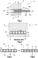
- FIG. 1 schematically describes a welding device 10 suitable for magnetic pulse welding of an article 50 comprising at least one stack 55 of sheets 56.
- the various parts forming the article 50 can be of flat shape, or alternatively, of tubular shape.
- flat shape it is meant that the parts have at least one flat surface, or substantially flat, over all or part of their length, at least at the level of a zone of overlap of the parts between them.
- tubular shape it is meant that the parts have the shape of a tube over all or part of their length, at least at the level of a zone where the parts overlap with each other.
- the welding device 10 comprises in known manner a coil 11, a storage unit (not shown) and one or more switches (not shown).
- the storage unit is configured for and intended to store high energy, for example of the order of a few tens of kilojoules (kJ).
- the storage unit is a discharge capacitor bank.
- Coil 11 is configured for and intended to create a concentrated magnetic field in a delimited space.
- the coil 11 comprises a body 12.
- This body 12 is made of a material having specific characteristics in terms, on the one hand, of mechanical resistance to plastic deformation and, on the other hand, of high electrical conductivity to cause a current to flow therein. of very high intensity, of the order of a few hundred thousand Amperes.
- the body material is steel, preferably high strength steel.
- the body 12 When the switch(es) close, the body 12 is connected to the storage unit, and a strong current flows through it producing a magnetic field.
- the coil 11 is designed so that the current density in a zone of said coil is sufficient to satisfy the welding conditions. This zone is called the active part 121.
- the current is concentrated, in the active part, on a layer delimited by an active part and of thickness corresponding to the thickness of the skin.
- the skin thickness is of the order of a few millimeters for a frequency of a few tens of kHz.
- the frequency generated is at least greater than 25 kHz.
- the frequency generated is at least greater than 70 kHz.
- the article 50 to be welded comprises a stack 55 of sheets and two plates, called the first plate 51 and the second plate 52.
- the stack 55 comprises a superposition of sheets. It comprises a first sheet 56 a , a last sheet 56 c , and between these two sheets, intermediate sheets 56 b .
- the stack 55 is sandwiched between all or part of the two plates 51, 52.
- all or part of an internal face 511 of the first plate 51 is placed against the first sheet 56 a and all part of an internal face 521 of the second plate 52 is placed against the last sheet 56c .
- the stack 55 and the two plates 51, 52 are intended to be arranged one on top of the other, so as to form a common superposition zone, called the overlap zone 53, then to be welded at all or part of the said area covered by coil 11.
- the stack 55 and the two plates 51, 52 are positioned on top of each other in a substantially parallel manner, at least at the level of the overlap zone 53.
- the overlap zone 53 is located at one end of at least one plate, for example one end 513 of the first plate 51.
- Each plate 51, 52 can have a thickness comprised for example between 200 and 400 ⁇ m.
- Each plate 51, 52 is preferably made of a metallic material.
- the plates 51, 52 are made of aluminum.
- the plates 51, 52 are made of copper.
- the two plates 51, 52 are made of different metallic materials.
- the stack 55 comprises nine sheets, without this being limiting of the invention.
- the stack 55 comprises at least 40 sheets.
- Each sheet has for example a thickness of 20 ⁇ m.
- Each sheet is preferably made of a metallic material.
- the sheets are made of aluminum.
- the stack 55 has, in its thickness, and by extension each sheet, a plurality of through-perforations 60.
- a through-perforation will be referred to as perforation.
- the stack 55 can only comprise, in its thickness, a single perforation 60.
- the description below also applies to this case.
- the perforations 60 are positioned in the stack 55 such that when the two plates 51, 52 and the stack 55 are assembled, the perforations 60 are located in the overlap zone 53.
- the perforations 60 are substantially aligned.
- THE figures 2 to 4 illustrate a section of the article 50, at the level of a line of perforations 60, before the welding operation.
- the perforations 60 are six in number.
- perforations 60 are illustrated in the figures and described in number six, the number of these perforations is not limited to that described and illustrated. Thus, it is possible, without departing from the scope of the invention, to produce a stack 55 with a number of perforations less than or greater than 6.
- the number of perforations 60 obviously depends on the dimensions of the stack 55.
- the number, shape and dimension of the perforations is chosen according to the dimensions of the overlap zone and/or the thickness of the stack.
- a perforation 60 is made in the stack 55 so that said perforation has, whatever its shape, a mean axis 61 oriented substantially perpendicular to the internal face of the first 51, or second plate 52 , at said perforation.
- the middle axis of the perforation 60 is inclined substantially with respect to an axis perpendicular to the internal face of the first or second plate, at the level of said perforation.
- the perforations 60 have a cylindrical shape.
- cylindrical shape we mean a shape of constant section between the internal face 511 of the first plate 51 towards the internal face 521 of the second plate 52.
- the cylindrical shape includes any shape of cross section, such as for example an elliptical, circular, square, rectangular or polygonal section.
- the perforations 60 have a cylindrical shape, of circular cross-section.
- FIG 5 illustrates a top view of a sheet, for example the first sheet 56 a , comprising 6 perforations of circular cross section.
- the perforations 60 have a cylindrical shape, with an elliptical cross-section.
- FIG 6 illustrates a top view of a sheet, for example the first sheet 56a , comprising 6 perforations of elliptical cross-section.
- the perforations 60 have a substantially truncated cone shape, with a large base 62 located on the side of the internal face 511 of the first plate 51 and a small base 63 located on the side of the internal face 521 of the second plate 52.
- shape substantially in the form of a truncated cone we mean a shape of monotonous decreasing or increasing cross-section, here decreasing from the internal face 511 of the first plate 51 towards the internal face 521 of the second plate 52.
- truncated cone used to describe the shape of the perforation is to be taken in the general sense encompassing any shape of section of the truncated cone, such as for example an elliptical, circular, square, rectangular or polygonal section.
- the truncated cone can be a truncated cone of revolution or an oblique truncated cone.
- the perforations 60 have the shape of two inverted hollow truncated cones connected to each other at their small base, so as to have the shape of a diabolo.
- a first truncated cone has a large base located on the side of the inner face 511 of the first plate 51.
- a second truncated cone has a large base located on the side of the inner face 521 of the second plate 52.
- the two truncated cones are coaxial.
- the two truncated cones are of the same dimensions.
- the two truncated cones are asymmetrical.
- the present invention is not limited to a stack 55 with perforations 60 having the same shape.
- a stack 55 may comprise perforations 60 having different shapes. Those skilled in the art are able to adapt the invention to shapes and arrangements not described.
- two adjoining perforations 60 are spaced apart two by two by a distance equivalent to a maximum dimension of the cross section of a perforation.
- the perforations 60 are all spaced apart in pairs by a distance substantially equal to the diameter of the perforations.
- the perforations 60 have a diameter of 50 mm and are spaced apart by 50 mm.
- the perforations 60 are made in the stack 55.
- Perforations 60 are made in the stack where magnetic pulse welding is desired on the article.
- the sheets 56 are stacked beforehand, then the perforations are made simultaneously for all the sheets.
- the perforations are made for each sheet and then the sheets are stacked so as to align the mean axes 61 of the perforations 60.
- the perforations 60 are made by machining, for example by drilling or by punching.
- the two plates 51, 52 are arranged on either side of the stack 55, forming the overlap zone 53 covering at least the perforations 60 previously made.
- the inner face 511 of the first plate 51 is placed against the first sheet.
- the internal face 521 of the second plate 52 is placed against the last sheet.
- the method then includes a step of positioning the plate-stack assembly in the welding device 10.
- the stack 55 and the two plates 51, 52 are advantageously positioned at the level of the coil 11 so that all or part of the overlap zone 53 is opposite the active part 121 of said coil.
- the overlap zone 53 facing the active part 121 of the coil is called the working zone.
- the work area covers 60 perforations.
- the first plate 51 is the part closest to the active part 121 of the coil.
- An outer face 512 of the first plate 51 is arranged opposite the active part 121 of the coil.
- An outer face 522 of the second plate 52 is arranged opposite a wedge 13.
- the two plates 51, 52 and the stack 55 are maintained, close to the active part 121 of the coil 11, in a substantially parallel to each other, at least at the level of the overlap zone 53, by fastening means (not shown in the figures).
- the article is ready to be welded.
- the method then includes a magnetic pulse welding step.
- the switch(es) 51 close(s), the body 12 of the coil 11 is connected to the storage unit, and a high intensity current flows in the coil 11.
- the current generates, in a space delimited between the working area and the active part 121, a concentrated magnetic field coming from said active part.
- the article 50 is welded at the level of the working zone.
- the two plates 51, 52 and the stack 55 are bonded together by welding between the perforations 60, and the two plates 51, 52 are bonded together by welding in the perforations 60.
- the stack comprises 40 sheets 56 of aluminum. Both plates are aluminum.
- the overlap zone 53 has a dimension of 430 mm in length and 120 mm in width.
- the perforations are cylindrical, of the same circular cross-section, with a diameter of 50 mm, 5 in number and spaced two by two by 50 mm.
- the method is also adaptable to tubular parts.
- the present invention achieves the set objectives.
- it provides a magnetic pulse welding method suitable for welding parts comprising a stack of laminations.
Landscapes
- Engineering & Computer Science (AREA)
- Mechanical Engineering (AREA)
- Pressure Welding/Diffusion-Bonding (AREA)
- Manufacturing Cores, Coils, And Magnets (AREA)
Claims (9)
- Verfahren zum Magnetimpulsschweißen eines Artikels (50), der eine Stapelung (55) von Blechen aus metallischem Werkstoff beinhaltet, wobei das Verfahren beinhaltet:- die Verwirklichung mindestens einer Durchgangsperforation (60) in einer Dicke der Stapelung (55),- die Anordnung zweier Platten, erste (51) und zweite Platte (52) genannt, aus metallischem Werkstoff beiderseits der Stapelung durch Bilden eines Abdeckbereichs (53), der die mindestens eine Durchgangsperforation (60) abdeckt,- die Positionierung der Einheit aus Platten-Stapelung gegenüber einem aktiven Teil (121) einer Spule (11), derart, dass ein Arbeitsbereich des Abdeckbereichs auf Höhe des aktiven Teils der Spule angeordnet ist, wobei der Arbeitsbereich die mindestens eine Perforation (60) abdeckt,- das Unterziehen des Arbeitsbereichs einem Magnetfeld bis zur Verbindung der Einheit, wobei im Bereich der mindestens einen Perforation (60) ein Druck auf die erste Platte (51) ausgeübt wird, und sie gegen die zweite Platte (52) drückt, sodass es zu einem direkten Kontakt und einer dauerhaften Verschweißung zwischen der ersten Platte und der zweiten Platte kommt.
- Schweißverfahren nach Anspruch 1, wobei eine Durchgangsperforation (60) in Form eines Kegelstumpfes verwirklicht wird.
- Schweißverfahren nach Anspruch 1, wobei eine Durchgangsperforation (60) in Form eines Zylinders mit elliptischem Querschnitt verwirklicht wird.
- Schweißverfahren nach einem der vorstehenden Ansprüche, wobei die Durchgangsperforation (60) derart verwirklicht wird, um eine mittlere Achse aufzuweisen, die im Wesentlichen senkrecht zu einer Seite der einen der beiden Platten ausgerichtet (61) ist.
- Schweißverfahren nach einem der Ansprüche 1 bis 3, wobei die Durchgangsperforation (60) derart verwirklicht wird, um eine mittlere Achse (61) aufzuweisen, die in Bezug zu einer Normalen zu einer Seite der einen der beiden Platten im Bereich der Durchgangsperforation schräggestellt ist.
- Artikel (50), der eine Stapelung (55) von Blechen aus metallischem Werkstoff zwischen zwei Platten (51, 52) aus metallischem Werkstoff beinhaltet,
wobei die Stapelung in ihrer Dicke eine Durchgangsperforation (60) beinhaltet, wobei die Stapelung zwischen den beiden Platten, im Bereich eines Abdeckbereichs enthalten ist, der die Durchgangsperforation abdeckt, und die Einheit aus Platten-Stapelung auf nicht umkehrbare Art und Weise im Bereich eines Teils des Abdeckbereichs, der die Perforation abdeckt, verschweißt wird, dadurch gekennzeichnet, dass die beiden Platten im Bereich der Durchgangsperforation (60) miteinander verschweißt werden. - Artikel nach Anspruch 6, wobei sich eine Durchgangsperforation (60) in Form eines Kegelstumpfes darstellt.
- Artikel nach Anspruch 6, wobei sich eine Durchgangsperforation (60) in Form eines Zylinders mit elliptischem Querschnitt darstellt.
- Artikel nach einem der Ansprüche 6 bis 8, der zwei Durchgangsperforationen (60) mit einem selben Querschnitt und derselben Abmessung beinhaltet, wobei die Perforationen um die Abmessung einer Durchgangsperforation voneinander beabstandet sind.
Applications Claiming Priority (2)
| Application Number | Priority Date | Filing Date | Title |
|---|---|---|---|
| FR1660982A FR3058661B1 (fr) | 2016-11-14 | 2016-11-14 | Procede de soudage par impulsion magnetique d’un empilement de feuillets |
| PCT/EP2017/078943 WO2018087322A1 (fr) | 2016-11-14 | 2017-11-10 | Procédé de soudage par impulsion magnétique d'un empilement de feuillets |
Publications (2)
| Publication Number | Publication Date |
|---|---|
| EP3538313A1 EP3538313A1 (de) | 2019-09-18 |
| EP3538313B1 true EP3538313B1 (de) | 2023-08-30 |
Family
ID=57861078
Family Applications (1)
| Application Number | Title | Priority Date | Filing Date |
|---|---|---|---|
| EP17801411.4A Active EP3538313B1 (de) | 2016-11-14 | 2017-11-10 | Verfahren zum magnetimpulsschweissen eines blechstapels |
Country Status (6)
| Country | Link |
|---|---|
| US (1) | US11517976B2 (de) |
| EP (1) | EP3538313B1 (de) |
| JP (1) | JP7084395B2 (de) |
| CN (1) | CN109996638B (de) |
| FR (1) | FR3058661B1 (de) |
| WO (1) | WO2018087322A1 (de) |
Families Citing this family (4)
| Publication number | Priority date | Publication date | Assignee | Title |
|---|---|---|---|---|
| JP7310337B2 (ja) * | 2019-06-10 | 2023-07-19 | マツダ株式会社 | 接合方法及びその方法で接合される複合材料 |
| CN113399808B (zh) * | 2021-06-22 | 2022-07-19 | 南昌航空大学 | 一种航空航天薄壁环件电磁脉冲增材装置及方法 |
| CN113871184B (zh) * | 2021-09-17 | 2022-07-01 | 重庆大学 | 一种磁脉冲管件成形线圈的固定装置 |
| WO2023056023A1 (en) * | 2021-10-01 | 2023-04-06 | Ohio State Innovation Foundation | Method of forming an impulse weld |
Family Cites Families (19)
| Publication number | Priority date | Publication date | Assignee | Title |
|---|---|---|---|---|
| US5472772A (en) * | 1994-04-18 | 1995-12-05 | General Electric Company | Method for welding stacker laminations and article therefrom |
| US5981921A (en) * | 1997-06-20 | 1999-11-09 | Dana Corporation | Method of magnetic pulse welding an end fitting to a driveshaft tube of a vehicular driveshaft |
| US5966813A (en) * | 1997-12-23 | 1999-10-19 | Dana Corporation | Method for joining vehicle frame components |
| AR028029A1 (es) * | 2000-04-26 | 2003-04-23 | Cosma Int Inc | Hidroformado de una estructura tubular de diametro variable a partir de una preforma tubular, mediante la utilizacion de una soldadura de pulsacion electromagnetica |
| CN100513038C (zh) * | 2000-05-02 | 2009-07-15 | 约翰斯霍普金斯大学 | 使用可独立反应的多层薄片的结合方法以及结合结构 |
| US6389697B1 (en) * | 2000-07-17 | 2002-05-21 | Fuel Cell Components And Integrators, Inc. | Fabricating automotive spaceframes using electromagnetic forming or magnetic pulse welding |
| JP3852824B2 (ja) * | 2001-10-11 | 2006-12-06 | 独立行政法人科学技術振興機構 | 金属薄板の積層式電磁溶接方法 |
| KR20060025608A (ko) * | 2003-07-07 | 2006-03-21 | 펄사르 웰딩 엘티디. | 용기를 봉합하기 위한 자기 펄스 용접 방법 및 장치와봉합된 용기 |
| IL158705A (en) * | 2003-10-31 | 2009-06-15 | Pessach Seidel | A method of creating a stack for a heat exchanger |
| WO2006058241A1 (en) * | 2004-11-24 | 2006-06-01 | Dana Corporation | Method for performing a magnetic pulse welding operation to secure first and second metallic components with a preheating step for softening a first part of the first member |
| JP4473713B2 (ja) | 2004-11-26 | 2010-06-02 | 本田技研工業株式会社 | 摩擦撹拌接合方法 |
| US20060138199A1 (en) * | 2004-12-28 | 2006-06-29 | Nelson Precision Casting Co., Ltd. | Welding method for manufacturing a golf club head |
| JP5274944B2 (ja) * | 2008-09-08 | 2013-08-28 | 矢崎総業株式会社 | 導体モジュール及び電磁圧接方法 |
| TW201116353A (en) * | 2009-11-04 | 2011-05-16 | Metal Ind Res & Dev Ct | nal statically indeterminate truss structure |
| DE102011010216A1 (de) * | 2011-02-03 | 2012-08-09 | Pst Products Gmbh | Pulsschweißgerät zur Blechverschweißung |
| JP6210489B2 (ja) * | 2013-11-06 | 2017-10-11 | 公立大学法人首都大学東京 | 金属接合板の製造方法 |
| JP2016538556A (ja) * | 2013-11-27 | 2016-12-08 | トタル ソシエテ アノニムTotal Sa | キャピラリーカラムを有するガスクロマトグラフ用プレート、キャピラリー装置、およびガスクロマトグラフ |
| DE102014223138A1 (de) * | 2014-11-13 | 2016-05-19 | Robert Bosch Gmbh | Verbinden zweier Bauteile mittels Kaltverformung |
| JP6486735B2 (ja) * | 2015-03-17 | 2019-03-20 | 東芝メモリ株式会社 | 半導体製造方法および半導体製造装置 |
-
2016
- 2016-11-14 FR FR1660982A patent/FR3058661B1/fr not_active Expired - Fee Related
-
2017
- 2017-11-10 EP EP17801411.4A patent/EP3538313B1/de active Active
- 2017-11-10 CN CN201780069444.2A patent/CN109996638B/zh active Active
- 2017-11-10 US US16/343,406 patent/US11517976B2/en active Active
- 2017-11-10 WO PCT/EP2017/078943 patent/WO2018087322A1/fr not_active Ceased
- 2017-11-10 JP JP2019524063A patent/JP7084395B2/ja active Active
Also Published As
| Publication number | Publication date |
|---|---|
| US20190262932A1 (en) | 2019-08-29 |
| JP7084395B2 (ja) | 2022-06-14 |
| CN109996638A (zh) | 2019-07-09 |
| FR3058661A1 (fr) | 2018-05-18 |
| EP3538313A1 (de) | 2019-09-18 |
| FR3058661B1 (fr) | 2019-06-28 |
| JP2019537512A (ja) | 2019-12-26 |
| WO2018087322A1 (fr) | 2018-05-17 |
| US11517976B2 (en) | 2022-12-06 |
| CN109996638B (zh) | 2021-07-30 |
Similar Documents
| Publication | Publication Date | Title |
|---|---|---|
| EP1134820B1 (de) | Verfahren zum Verbinden von Elektrodenfahnen mit einem Pol eines elektrochemischen Generators und Generator | |
| FR3058661B1 (fr) | Procede de soudage par impulsion magnetique d’un empilement de feuillets | |
| WO2016046248A1 (fr) | Bobine pour soudage de pièces plates par impulsion magnétique et procédé de soudage associé | |
| EP3089836B1 (de) | Verfahren zum befestigen eines metallrings in einem rahmen und durch dieses verfahren erhaltene induktionsspule | |
| EP3197628B1 (de) | Spule für magnetimpulsschweissen von rohrförmigen teilen und zugehöriges schweissverfahren | |
| EP3073551B1 (de) | Elektrochemischer generator | |
| WO2014090902A1 (fr) | Procédé d'assemblage par sertissage magnétique | |
| WO2010061094A1 (fr) | Dispositif de soudage a double épaulement | |
| CA2931046A1 (fr) | Cale d'epaisseur d'interposition entre les surfaces en regard de deux pieces. | |
| WO2015055626A1 (fr) | Procédé de sertissage par impulsion magnétique | |
| EP3731989B1 (de) | Verfahren zur montage eines ringes in einem rohrstück durch magnetimpuls | |
| EP3720626B1 (de) | Verfahren zum formen/schweissen von teilen mittels magnetimpuls | |
| EP3455023B1 (de) | Verfahren zum verbinden von sehr dicken rohrförmigen teilen durch magnetische impulse | |
| WO2017064174A1 (fr) | Element de refroidissement avec embase pour evacuer de la chaleur d'un emballage | |
| EP2402700A1 (de) | Wärmetauscher | |
| WO2012153182A1 (fr) | Assemblage d'un tube et d'une tôle | |
| EP0615074A1 (de) | Aus Blöcken bestehender Bremsbelag mit verbesserter Befestigung dieser Blöcke | |
| EP3268208B1 (de) | Verfahren zum laminieren eines heissschmelzartikels mittels ultraschall und laminiervorrichtung zur durchführung des verfahrens | |
| FR3101267A3 (fr) | Procédé de fabrication d’un élément intercalaire pour échangeur de chaleur | |
| WO2024213683A1 (fr) | Pion a souder et procédé d'assemblage | |
| FR2997879A1 (fr) | Procede de soudage a grande vitesse de deux parois de deux pieces | |
| FR3149529A1 (fr) | Module métallique et procédé de fabrication d’un tel module métallique. | |
| WO2022162321A1 (fr) | Ressort à forte puissance et faible encombrement | |
| FR2959431A1 (fr) | Dispositif d'assemblage a sertir | |
| FR2892327A1 (fr) | Procede de fixation d'un organe metallique a l'aide d'un dispositif de soudage par points |
Legal Events
| Date | Code | Title | Description |
|---|---|---|---|
| STAA | Information on the status of an ep patent application or granted ep patent |
Free format text: STATUS: UNKNOWN |
|
| STAA | Information on the status of an ep patent application or granted ep patent |
Free format text: STATUS: THE INTERNATIONAL PUBLICATION HAS BEEN MADE |
|
| PUAI | Public reference made under article 153(3) epc to a published international application that has entered the european phase |
Free format text: ORIGINAL CODE: 0009012 |
|
| STAA | Information on the status of an ep patent application or granted ep patent |
Free format text: STATUS: REQUEST FOR EXAMINATION WAS MADE |
|
| 17P | Request for examination filed |
Effective date: 20190405 |
|
| AK | Designated contracting states |
Kind code of ref document: A1 Designated state(s): AL AT BE BG CH CY CZ DE DK EE ES FI FR GB GR HR HU IE IS IT LI LT LU LV MC MK MT NL NO PL PT RO RS SE SI SK SM TR |
|
| AX | Request for extension of the european patent |
Extension state: BA ME |
|
| DAV | Request for validation of the european patent (deleted) | ||
| DAX | Request for extension of the european patent (deleted) | ||
| GRAP | Despatch of communication of intention to grant a patent |
Free format text: ORIGINAL CODE: EPIDOSNIGR1 |
|
| STAA | Information on the status of an ep patent application or granted ep patent |
Free format text: STATUS: GRANT OF PATENT IS INTENDED |
|
| INTG | Intention to grant announced |
Effective date: 20220912 |
|
| GRAJ | Information related to disapproval of communication of intention to grant by the applicant or resumption of examination proceedings by the epo deleted |
Free format text: ORIGINAL CODE: EPIDOSDIGR1 |
|
| STAA | Information on the status of an ep patent application or granted ep patent |
Free format text: STATUS: REQUEST FOR EXAMINATION WAS MADE |
|
| INTC | Intention to grant announced (deleted) | ||
| GRAP | Despatch of communication of intention to grant a patent |
Free format text: ORIGINAL CODE: EPIDOSNIGR1 |
|
| STAA | Information on the status of an ep patent application or granted ep patent |
Free format text: STATUS: GRANT OF PATENT IS INTENDED |
|
| INTG | Intention to grant announced |
Effective date: 20230330 |
|
| GRAS | Grant fee paid |
Free format text: ORIGINAL CODE: EPIDOSNIGR3 |
|
| GRAA | (expected) grant |
Free format text: ORIGINAL CODE: 0009210 |
|
| STAA | Information on the status of an ep patent application or granted ep patent |
Free format text: STATUS: THE PATENT HAS BEEN GRANTED |
|
| RAP1 | Party data changed (applicant data changed or rights of an application transferred) |
Owner name: ADM28 FRANCE |
|
| AK | Designated contracting states |
Kind code of ref document: B1 Designated state(s): AL AT BE BG CH CY CZ DE DK EE ES FI FR GB GR HR HU IE IS IT LI LT LU LV MC MK MT NL NO PL PT RO RS SE SI SK SM TR |
|
| REG | Reference to a national code |
Ref country code: GB Ref legal event code: FG4D Free format text: NOT ENGLISH |
|
| REG | Reference to a national code |
Ref country code: CH Ref legal event code: EP |
|
| REG | Reference to a national code |
Ref country code: DE Ref legal event code: R096 Ref document number: 602017073486 Country of ref document: DE |
|
| REG | Reference to a national code |
Ref country code: IE Ref legal event code: FG4D Free format text: LANGUAGE OF EP DOCUMENT: FRENCH |
|
| REG | Reference to a national code |
Ref country code: LT Ref legal event code: MG9D |
|
| REG | Reference to a national code |
Ref country code: NL Ref legal event code: MP Effective date: 20230830 |
|
| REG | Reference to a national code |
Ref country code: AT Ref legal event code: MK05 Ref document number: 1604799 Country of ref document: AT Kind code of ref document: T Effective date: 20230830 |
|
| PG25 | Lapsed in a contracting state [announced via postgrant information from national office to epo] |
Ref country code: GR Free format text: LAPSE BECAUSE OF FAILURE TO SUBMIT A TRANSLATION OF THE DESCRIPTION OR TO PAY THE FEE WITHIN THE PRESCRIBED TIME-LIMIT Effective date: 20231201 |
|
| PG25 | Lapsed in a contracting state [announced via postgrant information from national office to epo] |
Ref country code: IS Free format text: LAPSE BECAUSE OF FAILURE TO SUBMIT A TRANSLATION OF THE DESCRIPTION OR TO PAY THE FEE WITHIN THE PRESCRIBED TIME-LIMIT Effective date: 20231230 |
|
| PG25 | Lapsed in a contracting state [announced via postgrant information from national office to epo] |
Ref country code: SE Free format text: LAPSE BECAUSE OF FAILURE TO SUBMIT A TRANSLATION OF THE DESCRIPTION OR TO PAY THE FEE WITHIN THE PRESCRIBED TIME-LIMIT Effective date: 20230830 Ref country code: RS Free format text: LAPSE BECAUSE OF FAILURE TO SUBMIT A TRANSLATION OF THE DESCRIPTION OR TO PAY THE FEE WITHIN THE PRESCRIBED TIME-LIMIT Effective date: 20230830 Ref country code: NO Free format text: LAPSE BECAUSE OF FAILURE TO SUBMIT A TRANSLATION OF THE DESCRIPTION OR TO PAY THE FEE WITHIN THE PRESCRIBED TIME-LIMIT Effective date: 20231130 Ref country code: LV Free format text: LAPSE BECAUSE OF FAILURE TO SUBMIT A TRANSLATION OF THE DESCRIPTION OR TO PAY THE FEE WITHIN THE PRESCRIBED TIME-LIMIT Effective date: 20230830 Ref country code: LT Free format text: LAPSE BECAUSE OF FAILURE TO SUBMIT A TRANSLATION OF THE DESCRIPTION OR TO PAY THE FEE WITHIN THE PRESCRIBED TIME-LIMIT Effective date: 20230830 Ref country code: IS Free format text: LAPSE BECAUSE OF FAILURE TO SUBMIT A TRANSLATION OF THE DESCRIPTION OR TO PAY THE FEE WITHIN THE PRESCRIBED TIME-LIMIT Effective date: 20231230 Ref country code: HR Free format text: LAPSE BECAUSE OF FAILURE TO SUBMIT A TRANSLATION OF THE DESCRIPTION OR TO PAY THE FEE WITHIN THE PRESCRIBED TIME-LIMIT Effective date: 20230830 Ref country code: GR Free format text: LAPSE BECAUSE OF FAILURE TO SUBMIT A TRANSLATION OF THE DESCRIPTION OR TO PAY THE FEE WITHIN THE PRESCRIBED TIME-LIMIT Effective date: 20231201 Ref country code: FI Free format text: LAPSE BECAUSE OF FAILURE TO SUBMIT A TRANSLATION OF THE DESCRIPTION OR TO PAY THE FEE WITHIN THE PRESCRIBED TIME-LIMIT Effective date: 20230830 Ref country code: AT Free format text: LAPSE BECAUSE OF FAILURE TO SUBMIT A TRANSLATION OF THE DESCRIPTION OR TO PAY THE FEE WITHIN THE PRESCRIBED TIME-LIMIT Effective date: 20230830 |
|
| PG25 | Lapsed in a contracting state [announced via postgrant information from national office to epo] |
Ref country code: PL Free format text: LAPSE BECAUSE OF FAILURE TO SUBMIT A TRANSLATION OF THE DESCRIPTION OR TO PAY THE FEE WITHIN THE PRESCRIBED TIME-LIMIT Effective date: 20230830 Ref country code: NL Free format text: LAPSE BECAUSE OF FAILURE TO SUBMIT A TRANSLATION OF THE DESCRIPTION OR TO PAY THE FEE WITHIN THE PRESCRIBED TIME-LIMIT Effective date: 20230830 |
|
| PG25 | Lapsed in a contracting state [announced via postgrant information from national office to epo] |
Ref country code: ES Free format text: LAPSE BECAUSE OF FAILURE TO SUBMIT A TRANSLATION OF THE DESCRIPTION OR TO PAY THE FEE WITHIN THE PRESCRIBED TIME-LIMIT Effective date: 20230830 |
|
| PG25 | Lapsed in a contracting state [announced via postgrant information from national office to epo] |
Ref country code: SM Free format text: LAPSE BECAUSE OF FAILURE TO SUBMIT A TRANSLATION OF THE DESCRIPTION OR TO PAY THE FEE WITHIN THE PRESCRIBED TIME-LIMIT Effective date: 20230830 Ref country code: RO Free format text: LAPSE BECAUSE OF FAILURE TO SUBMIT A TRANSLATION OF THE DESCRIPTION OR TO PAY THE FEE WITHIN THE PRESCRIBED TIME-LIMIT Effective date: 20230830 Ref country code: ES Free format text: LAPSE BECAUSE OF FAILURE TO SUBMIT A TRANSLATION OF THE DESCRIPTION OR TO PAY THE FEE WITHIN THE PRESCRIBED TIME-LIMIT Effective date: 20230830 Ref country code: EE Free format text: LAPSE BECAUSE OF FAILURE TO SUBMIT A TRANSLATION OF THE DESCRIPTION OR TO PAY THE FEE WITHIN THE PRESCRIBED TIME-LIMIT Effective date: 20230830 Ref country code: DK Free format text: LAPSE BECAUSE OF FAILURE TO SUBMIT A TRANSLATION OF THE DESCRIPTION OR TO PAY THE FEE WITHIN THE PRESCRIBED TIME-LIMIT Effective date: 20230830 Ref country code: CZ Free format text: LAPSE BECAUSE OF FAILURE TO SUBMIT A TRANSLATION OF THE DESCRIPTION OR TO PAY THE FEE WITHIN THE PRESCRIBED TIME-LIMIT Effective date: 20230830 Ref country code: PT Free format text: LAPSE BECAUSE OF FAILURE TO SUBMIT A TRANSLATION OF THE DESCRIPTION OR TO PAY THE FEE WITHIN THE PRESCRIBED TIME-LIMIT Effective date: 20240102 Ref country code: SK Free format text: LAPSE BECAUSE OF FAILURE TO SUBMIT A TRANSLATION OF THE DESCRIPTION OR TO PAY THE FEE WITHIN THE PRESCRIBED TIME-LIMIT Effective date: 20230830 |
|
| PG25 | Lapsed in a contracting state [announced via postgrant information from national office to epo] |
Ref country code: IT Free format text: LAPSE BECAUSE OF FAILURE TO SUBMIT A TRANSLATION OF THE DESCRIPTION OR TO PAY THE FEE WITHIN THE PRESCRIBED TIME-LIMIT Effective date: 20230830 |
|
| REG | Reference to a national code |
Ref country code: DE Ref legal event code: R097 Ref document number: 602017073486 Country of ref document: DE |
|
| REG | Reference to a national code |
Ref country code: CH Ref legal event code: PL |
|
| PG25 | Lapsed in a contracting state [announced via postgrant information from national office to epo] |
Ref country code: MC Free format text: LAPSE BECAUSE OF FAILURE TO SUBMIT A TRANSLATION OF THE DESCRIPTION OR TO PAY THE FEE WITHIN THE PRESCRIBED TIME-LIMIT Effective date: 20230830 |
|
| PLBE | No opposition filed within time limit |
Free format text: ORIGINAL CODE: 0009261 |
|
| STAA | Information on the status of an ep patent application or granted ep patent |
Free format text: STATUS: NO OPPOSITION FILED WITHIN TIME LIMIT |
|
| PG25 | Lapsed in a contracting state [announced via postgrant information from national office to epo] |
Ref country code: LU Free format text: LAPSE BECAUSE OF NON-PAYMENT OF DUE FEES Effective date: 20231110 |
|
| PG25 | Lapsed in a contracting state [announced via postgrant information from national office to epo] |
Ref country code: CH Free format text: LAPSE BECAUSE OF NON-PAYMENT OF DUE FEES Effective date: 20231130 |
|
| PG25 | Lapsed in a contracting state [announced via postgrant information from national office to epo] |
Ref country code: MC Free format text: LAPSE BECAUSE OF FAILURE TO SUBMIT A TRANSLATION OF THE DESCRIPTION OR TO PAY THE FEE WITHIN THE PRESCRIBED TIME-LIMIT Effective date: 20230830 Ref country code: LU Free format text: LAPSE BECAUSE OF NON-PAYMENT OF DUE FEES Effective date: 20231110 Ref country code: CH Free format text: LAPSE BECAUSE OF NON-PAYMENT OF DUE FEES Effective date: 20231130 Ref country code: SI Free format text: LAPSE BECAUSE OF FAILURE TO SUBMIT A TRANSLATION OF THE DESCRIPTION OR TO PAY THE FEE WITHIN THE PRESCRIBED TIME-LIMIT Effective date: 20230830 |
|
| REG | Reference to a national code |
Ref country code: BE Ref legal event code: MM Effective date: 20231130 |
|
| 26N | No opposition filed |
Effective date: 20240603 |
|
| REG | Reference to a national code |
Ref country code: IE Ref legal event code: MM4A |
|
| PG25 | Lapsed in a contracting state [announced via postgrant information from national office to epo] |
Ref country code: IE Free format text: LAPSE BECAUSE OF NON-PAYMENT OF DUE FEES Effective date: 20231110 |
|
| PG25 | Lapsed in a contracting state [announced via postgrant information from national office to epo] |
Ref country code: BE Free format text: LAPSE BECAUSE OF NON-PAYMENT OF DUE FEES Effective date: 20231130 |
|
| PG25 | Lapsed in a contracting state [announced via postgrant information from national office to epo] |
Ref country code: IE Free format text: LAPSE BECAUSE OF NON-PAYMENT OF DUE FEES Effective date: 20231110 Ref country code: BE Free format text: LAPSE BECAUSE OF NON-PAYMENT OF DUE FEES Effective date: 20231130 |
|
| PG25 | Lapsed in a contracting state [announced via postgrant information from national office to epo] |
Ref country code: BG Free format text: LAPSE BECAUSE OF FAILURE TO SUBMIT A TRANSLATION OF THE DESCRIPTION OR TO PAY THE FEE WITHIN THE PRESCRIBED TIME-LIMIT Effective date: 20230830 |
|
| PG25 | Lapsed in a contracting state [announced via postgrant information from national office to epo] |
Ref country code: BG Free format text: LAPSE BECAUSE OF FAILURE TO SUBMIT A TRANSLATION OF THE DESCRIPTION OR TO PAY THE FEE WITHIN THE PRESCRIBED TIME-LIMIT Effective date: 20230830 |
|
| PG25 | Lapsed in a contracting state [announced via postgrant information from national office to epo] |
Ref country code: CY Free format text: LAPSE BECAUSE OF FAILURE TO SUBMIT A TRANSLATION OF THE DESCRIPTION OR TO PAY THE FEE WITHIN THE PRESCRIBED TIME-LIMIT; INVALID AB INITIO Effective date: 20171110 |
|
| PG25 | Lapsed in a contracting state [announced via postgrant information from national office to epo] |
Ref country code: HU Free format text: LAPSE BECAUSE OF FAILURE TO SUBMIT A TRANSLATION OF THE DESCRIPTION OR TO PAY THE FEE WITHIN THE PRESCRIBED TIME-LIMIT; INVALID AB INITIO Effective date: 20171110 |
|
| PG25 | Lapsed in a contracting state [announced via postgrant information from national office to epo] |
Ref country code: TR Free format text: LAPSE BECAUSE OF FAILURE TO SUBMIT A TRANSLATION OF THE DESCRIPTION OR TO PAY THE FEE WITHIN THE PRESCRIBED TIME-LIMIT Effective date: 20230830 |
|
| PGFP | Annual fee paid to national office [announced via postgrant information from national office to epo] |
Ref country code: DE Payment date: 20251127 Year of fee payment: 9 |
|
| PGFP | Annual fee paid to national office [announced via postgrant information from national office to epo] |
Ref country code: GB Payment date: 20251127 Year of fee payment: 9 |
|
| PGFP | Annual fee paid to national office [announced via postgrant information from national office to epo] |
Ref country code: FR Payment date: 20251126 Year of fee payment: 9 |