EP3538384B1 - Pneumatique de véhicule - Google Patents
Pneumatique de véhicule Download PDFInfo
- Publication number
- EP3538384B1 EP3538384B1 EP17762057.2A EP17762057A EP3538384B1 EP 3538384 B1 EP3538384 B1 EP 3538384B1 EP 17762057 A EP17762057 A EP 17762057A EP 3538384 B1 EP3538384 B1 EP 3538384B1
- Authority
- EP
- European Patent Office
- Prior art keywords
- spike
- depressions
- annular surface
- hole
- den
- Prior art date
- Legal status (The legal status is an assumption and is not a legal conclusion. Google has not performed a legal analysis and makes no representation as to the accuracy of the status listed.)
- Active
Links
Images












Classifications
-
- B—PERFORMING OPERATIONS; TRANSPORTING
- B60—VEHICLES IN GENERAL
- B60C—VEHICLE TYRES; TYRE INFLATION; TYRE CHANGING; CONNECTING VALVES TO INFLATABLE ELASTIC BODIES IN GENERAL; DEVICES OR ARRANGEMENTS RELATED TO TYRES
- B60C11/00—Tyre tread bands; Tread patterns; Anti-skid inserts
- B60C11/14—Anti-skid inserts, e.g. vulcanised into the tread band
- B60C11/16—Anti-skid inserts, e.g. vulcanised into the tread band of plug form, e.g. made from metal, textile
- B60C11/1637—Attachment of the plugs into the tread, e.g. screwed
Definitions
- the invention relates to a vehicle tire with a tread pattern and stud holes for receiving studs, which are each delimited in the radial direction R inward by a hole base.
- spike holes are usually formed in the tread profile of the pneumatic vehicle tire.
- the main task of these stud holes is to enable the stud to be firmly anchored in the rubber matrix of the tread and thus to avoid the loss of studs when the vehicle tire rolls off during use.
- the hole geometry of the spike hole is usually adapted to the spike body geometry, but is significantly smaller than the spike body of the spike. The spikes are then literally pressed into these smaller spike holes with their spike body. This leads to strong tension in the rubber matrix surrounding the spike, which creates the desired holding forces.
- these tensions also have a massive influence on the lateral support of the spike and thus on the bedding rigidity of the spike in the tire, both in the transverse direction of the tire and in the circumferential direction of the tire.
- the braking and traction properties as well as lateral guidance properties of the spikes are also influenced by the resulting spike tilting.
- the tension also influences the radial bedding stiffness of the spike and thus the Contact force of the spike on the road surface and the ability of the spike to immerse itself in the flexible rubber matrix on contact with the road surface.
- the support effect of the rubber material acting outwards in the radial direction of the tire is, however, only slight with such a design, so that the spike can dive completely radially inwards in an uncontrolled manner under compression of the air even with low forces acting from the road and thus have any grip Ice loses.
- the narrow, ring-shaped rubber rim area outside the hollow chamber can be pressed radially away from the center of the hollow chamber when the spike foot is subjected to loads, which further promotes uncontrolled slipping and diving of the spike.
- the damping effect of the air formed in the hollow chamber is too low to enable effective damping.
- the damping effect produced by the rubber rim surrounding the central hollow chamber can hardly be developed either.
- the stud hole is usually molded into the tread material in the vulcanization mold.
- a fixed in the vulcanization mold and the desired shape of the stud hole correspondingly negatively formed form pin pressed into the rubber material of the tread during the formation of the tread profile in the radial direction of the green tire.
- the tread is usually made from a cap and base
- the from the DE 22 420 36 known spike hole when the forming pin is pressed in, the rubber rubber material of the cap strip formed in the radially outer extension section of the tread profile, into the desired material area of the base strip in the area of the spike hole, is uncontrollably pressed.
- the already low support effect of the rubber rim surrounding the central hollow chamber is further deteriorated in an uncontrolled manner.
- the design of the known pneumatic vehicle tire thus does not allow a targeted damping effect of the spike, but only an uncontrolled diving away.
- the grip effect on ice actually desired by the spikes is thus massively and uncontrollably impaired, without, however, allowing reliable damping of the spikes and thus protection of the road surface.
- a spike hole in which an annular recess is formed in the base of the spike hole, which after the spike has been inserted between the base of the spike and the annular recess creates a closed, annular hollow chamber in which the air enclosed therein is intended to cause damping.
- the rubber material enclosed within the annular recess by the annular recess should and may allow a limited supporting effect of the spikes.
- the rubber material in the area of the spike base can easily evade in an uncontrolled manner.
- the residual rubber strip remaining outside the depression can be pressed away more or less centrally from the annular chamber or pressed into the annular chamber in a simple manner.
- the central area enclosed by the annular recess can simply give way in the radial direction of the tire or in the radial direction of the ring, and more or less uncontrollably fill the cavity.
- the damping effect of the rubber material enclosed in the cavity is also relatively small in this embodiment when measured against the effective forces.
- the rubber section in the bottom of the spike hole surrounded by the annular recess has no lateral stiffening and can penetrate the cavity in an uncontrolled manner even with relatively low loads, so that the spike can simply submerge in an uncontrolled manner.
- the grip effect of the spikes is therefore not ensured in this embodiment either, but without reliably enabling a sufficiently good damping effect against radial loading of the spikes or against tilting of the spikes.
- this embodiment also enables the uncontrolled introduction of cap material into the area of the base of the spike hole, which is made possible when the spike hole is formed with the aid of a molding pin in the vulcanization mold.
- the annular recess which separates the rubber surface section of the spike hole base enclosed by the annular recess, from the rubber material surrounding outside the annular recess, leads in this embodiment to uncontrolled decoupling of the rubber material in the area of the spike hole base. Reliable cushioning is hardly achievable, especially with modern cap and baselets. Due to the rather random distribution of the cap material carried along during the molding in the area of the spike bottom with its higher damping property compared to the base material, accidental damping in one direction or the other is made possible. When rolling on ice, the spike can do more or less what it wants.
- the invention is therefore based on the object of enabling good damping of the spikes in the area of the stud holes in pneumatic vehicle tires with studs and thereby avoiding undesired dipping of the studs in the stud hole.
- the object is achieved according to the invention by the formation of a vehicle tire with a tread pattern and stud holes for receiving spikes, which in radial Direction R inwardly each bounded by a hole base, solved according to the features of claim 1, in which on an annular surface of the hole base several, each spaced apart depressions are arranged in a row distributed one behind the other in the circumferential direction of the ring.
- the design makes it possible for the spike hole base to be connected in a stiffening manner over its entire area of extent from the center of the spike hole base to the outer edge outside the annular surface between the depressions.
- the distribution and arrangement of the depressions one behind the other within an annular area enables a targeted evasion of the rubber material corresponding to the loads on the spike in the direction of the depressions of the spike hole, even if the rubber material is stronger outside the annular area formed with the depressions is stretched as the rubber material in the portion enclosed by the annular surface.
- This inner section, which is enclosed by the annular surface is therefore not stressed as much as the rubber section formed outside the annular surface and can in this way develop a good damping effect by compressing the rubber material.
- the connections of the inner section formed between the depressions to the outer section enclosing the annular surface also ensure sufficient rigidity of the spike hole base, whereby an undesired dipping away of the spikes can be effectively prevented in a targeted manner.
- the rigidity and the damping behavior can be set individually according to the requirements of the respective tire and its use.
- These webs formed by the connection in the area of the spike bottom also hinder uncontrolled remaining of cap material when the spike holes are formed.
- the cap material is not enclosed by a single annular recess during molding - as in the prior art - but can be pressed out and displaced by the base material during molding through the channels formed between the depressions formed on the annular surface.
- the design of a vehicle tire according to the features of claim 2 is particularly advantageous, the depressions being arranged so as to be uniformly distributed in the direction of the circumferential extent of the ring. In this way, uniform tensioning of the central damping element in the spike hole base can be set in a simple manner. As a result, when the spike is introduced, the central damping element is similarly stressed in all directions and similarly tensioned.
- the formation of a vehicle tire according to the features of claim 5 is particularly advantageous, the depressions of the annular surface each having a width b measured perpendicularly to the circumferential direction of the annular surface with a width b of 0.2mm ⁇ b ⁇ 1.5 mm, in particular of the same size.
- the width b of the annular surface With the help of the design of the width b of the annular surface, the size of the central damping element and thus its damping properties can be influenced by simple means.
- the width b is large enough for decoupling and good adjustment effective, and sufficiently small to enable a rigid connection of the central damping element to the rubber matrix surrounding the annular surface and to effectively prevent the creation of a cavity under the spike and the spike from diving under load.
- the design of a vehicle tire according to the features of claim 7 is particularly advantageous, the depressions of the annular surface each extending over a circumferential extension angle ⁇ of the annular surface with 5 ° ⁇ 120 °.
- the formation of a vehicle tire according to the features of claim 8 is particularly advantageous, the depressions of the annular surface being formed with at least partially different lengths L measured along the circumferential extension direction of the annular surface.
- the training is particularly advantageous for use for spike holes with not circular, but rather elliptical or oval shapes of shape pins and spikes. Since such shapes are often oriented in a specific direction in the tire profile and their design is adapted to the preferred loading directions.
- the different lengths of the depressions can be taken into account in a simple manner, the preferred loading directions with softening depressions and stiffening connections.
- a vehicle tire according to the features of claim 9 is particularly advantageous, one or more of the depressions of the annular row being formed in the stud hole base with an annular segment-shaped contour.
- the training is particularly suitable for designing the bedding rigidity in the case of not “circular”, but rather oval or elliptical spike shapes.
- the design of a vehicle tire according to the features of claim 10 is particularly advantageous, with four ring segment-shaped depressions, in particular concentric ones, arranged one behind the other in the bottom of the hole. In this way, the bedding stiffness can be influenced particularly well.
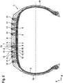
- the Figures 1 and 2 show a pneumatic vehicle tire 1 of a passenger car with winter properties for use with spikes.
- the pneumatic vehicle tire 1 is designed in a conventional manner with two side walls 10 delimiting the pneumatic vehicle tire in the axial direction A and with a profiled tread 9 delimiting the vehicle tire in the radial direction R towards the outside.
- the profiling of the tread is not shown for the sake of simplicity.
- the tire is conventionally designed with a carcass 2 of radial design, which, starting from the bead core of the sidewall 10 shown on the left, extends outwards in the radial direction R, then in the axial direction through the entire axial extent of the tire to the right side wall 10 shown and then extends in the radial direction inward through the side wall 10 shown on the right to the bead core of the right side wall.
- a single or multi-layer belt 3 is formed in a known manner on the carcass 2, which extends in the axial direction from the left tire shoulder to the right tire shoulder and in the circumferential direction over the entire tire.
- the tread 9 is constructed in a known manner from tread rubber material, which extends over the entire circumference of the vehicle pneumatic tire and in the axial direction from the left tire shoulder to the right tire shoulder.
- the tread 9 is formed, for example, in a known manner from a radially inner base layer and from a radially outer cap layer.
- In the tread 9 are over the entire circumference of the tire and - as in FIG Fig. 1 is shown - arranged distributed in the axial direction A over the axial extent A of the tread each formed in a known manner spike holes 5.
- the spike holes 5 each extend from the surface of the tread that delimits the tread radially outward, starting in the radial direction R of the tire inward with a radially outer extension section 6 and a Radially subsequently arranged radially inner extension section 7.
- the spike hole 5 is each cylindrical.
- the spike hole 5 is also cylindrical in each case.
- the cylinder shape in the radially inner extension section 7 and in the radially outer extension section 6 are concentric to one another, the cylinder shape in the radially inner extension section 7 having a larger cylinder diameter than the cylinder shape in the radially outer extension section 6.
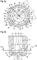
- the spike hole 5 is radially in the radially inner extension section 7 is bounded on the inside by a spike hole base 8. This is in the Figures 1 , 2 , 3c , 3a , 3b and 3d to recognize.
- Fig. 2 As well as the Fig.3d is the pneumatic vehicle tire from Fig.1 shown, in which a spike 11 is already pressed in a known manner into a correspondingly designed spike hole 5.
- the spike 11 is formed in a known manner from a spike body 12 and a spikepin 13.
- the spike body 12 is formed along its extension in the direction of the spike axis with an upper spike body section 14 and with an adjoining foot flange 15 which forms the lower section.
- the spike body section 14 is formed with an essentially cylindrical jacket surface.
- the foot flange 15 is formed with a cylindrical outer surface arranged concentrically to the cylindrical outer surface of the spike body section 14, the diameter of which is larger than the diameter of the cylindrical outer surface of the spike body section 14.
- the spike body section 14 is arranged in the radial direction of the tire outside the foot flange 15.
- the spike body 12 is downward in the axial direction of extent of the spike, i. E. bounded inward in the radial direction R of the tire by an end face which, in the inserted state in the stud hole 5, is in contact with the stud hole base 8.
- the spike body 12 is on its side facing away from the spike base 8 with an opening for receiving the spike pin 13 formed in which the spikepin 13 is positioned and secured in a conventional manner.
- the tread 4 is delimited outward in the radial direction by a radially outer surface 9 which forms the ground contact surface, which in the position of the spike hole 5 with the spike 11 inserted essentially flows into the end face of the spike body 12 pointing away from the spike hole base 8 transforms.
- the spikepin 13 extends in a known manner in the radial direction R of the tire outward beyond the position of the radially outer surface 9.
- an annular surface 17 is formed in the spike hole base 8, which is formed between a closed outer line 18 delimiting the annular surface 17 towards the outside and a closed inner line 19 delimiting the annular surface 17 towards the inside.
- Evenly distributed depressions 16 are formed in the base of the spike hole 8 over the circumference of the ring.
- the center M of the ring lies on the axis of the radially outer hole section 6 of the spike hole 5.
- the outer line 18 and the inner line 19 of the ring are concentric circles in the illustrated embodiment with the circle center M located in the spike hole base 8.
- the depressions 16 are arranged along the circumferential extent of the annular surface 17 distributed uniformly one behind the other over the circumference of the ring.
- the recesses 16 are thus formed with an extension length formed in the direction of the circumferential extension of the ring, which corresponds to the diameter d, and with a width b formed perpendicular to the direction of the circumferential extension of the ring, which corresponds to the width b of the annular surface.
- the depressions 16 are each formed at a distance from one another and extend along the circumferential extent of the ring at a circumferential extent angle ⁇ with 5 ° ⁇ 120 ° around the center point M. formed and positioned at a circumferential extension angle ⁇ with 5 ° ⁇ 80 ° around the center point M spaced from one another.
- the distance between two adjacent depressions 16 is 0.2 mm to 2 mm in each case.
- the diameter d of the depressions is 0.2 mm d 1.5 mm.
- the depressions are formed with a depth t 1 measured from the spike hole bottom 8 perpendicular to the spike hole bottom 8 with 0.2 mm t 1 2 mm.
- the depth of the stud holes 5 measured in the radial direction R of the tire between the radially outer surface 9 and the stud hole base 8 is formed in the usual manner in the range between 7 mm and 15 mm.
- the spike hole 5 is after pressing the spike 11 into the spike hole 5 due to the slightly larger outer diameter of the spike 11 compared to the hole diameters produced of the spike hole 5 along its extent between the radially outer surface 9 and the spike hole base 8 in its circumference to the outer diameter of the Spikes 11 widened, so that the spike 11 is enclosed under tension by the surrounding rubber material of the tread on its cylinder jacket surfaces and, due to the larger diameter of the spike foot 15 compared to the diameter of the upper extension section 14 of the spike body 12, also sits positively in the spike hole 5.
- rubber material of the particularly stressed section in the spike hole base 8 can penetrate into the depressions 16 closest to the stressed section and thereby absorb loads in a damping manner.
- the between two adjacent depressions 16 in the annular surface 17 each forms a web 20 and thus a rigid connection between the outside of the outer line 18 and the inside of the inner line 19 formed rubber material of the spike hole base 8, despite damping forces and moments acting on the spike base can be transmitted.
- the base of the spike hole 8 is configured conically outside the outer line 18 concentrically to the center point M.
- the base of the spike hole 8 thus rises continuously, starting from the line 18 to the cylindrical outer surface of diameter D, in the radial direction R of the tire.
- recesses 16 are formed distributed over the circumference of the annular surface 17.
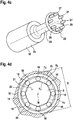
- the Figures 4a to 4c show a molding pin 23 which is used for producing this in FIGS Figures 3a to 3d Spikeloches 5 shown is used in the tire vulcanization trough.
- the form pin 23 is formed essentially from three sections formed along the extension axis of the form pin 23 with a lower form section 25, an adjoining upper form section 24 and with a fastening section 30.
- the upper mold section 24 corresponds with its outer surface to the negative of the inner contour to be formed of the radially outer extension section 6 of the spike hole 5.
- the lower mold section 25 corresponds with its outer surface to the negative of the inner contour to be formed of the radially inner extension section 7 of the spike hole 5 and is on its from the upper mold section 24 pioneering end face 26 is designed as a negative for shaping the bottom 8 of the spike hole.
- the pins 27 extend from the end face 26 to a height which corresponds to the depth t 1 of the depressions 16 to be shaped.
- the end face 26 for producing the spike hole base 8 is designed as a conical surface 28.
- the end face 26 is designed as a flat surface within the ring.
- the form pin 23 is formed at the extension end of the upper form section 24 facing away from the lower form section 25 with a cylindrical fastening section 30 with which the form pin 24 is fastened in the known manner in the tire vulcanization mold.
- an outer circumference U 2 is entered, which indicates the length of the shortest envelope line h 2 , which tangentially touches all of the depressions 16 on their outer side on the outer line 18 pointing away from the center point M.
- An inner circumference U 3 is also entered, which indicates the length of the shortest envelope line h 3 , which tangentially touches all of the depressions 16 in each case on their inner side pointing to the center point M on the inner line 19.
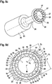
- FIGS 5a and 5b show an alternative design of the spike hole bottom 8, in which 16 recesses 16 are formed evenly distributed over the circumference of the annular surface 17.
- the forming pin 23 for producing this spike hole base 8 is accordingly designed with 16 pins 27.
- Fig.6d and Fig.5a As can be seen, this enables a high density of depressions 16 in the annular surface 17 and the circumferential lines U 2 and U 3 are almost circular.
- the circumferential line U 3 here almost corresponds to the inner line 19 and the circumferential line U 2 almost corresponds to the outer line 18 of the annular surface 17.
- FIG Fig. 6d the inner line 19 and the outer line 18 are not shown.
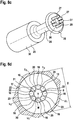
- FIGS Figures 3 and 4th show another embodiment of the spike hole base 8, in which, although as in FIGS Figures 3 and 4th only 8 wells 16 with - as in the Figures 8a to 8c 8 correspondingly designed pins 27 of the form pin 23 are produced.
- the inner line 19 and the outer line 18 are not shown.
- the outer line 18 and the inner line 19 are formed with a significantly smaller diameter than in that in FIG Figures 3 and 4th illustrated embodiment.
- a high density of depressions 16 is thus also implemented within the annular surface 17, but at a greater distance from the outer edge of the base 8 of the spike hole.
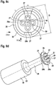
- Fig.9e is a further embodiment of a spike hole base 8 and in the Figures 9a to 9d for the formation of the spike hole base 8 of Fig.9e correspondingly designed form pin 23 is shown.
- the molding pin 23 is formed on its end face 26 in the extension region of the radially outer section 28 with circumferential extension sections 28a arranged one behind the other in an alternating sequence and with circumferential extension sections 28b.
- the circumferential extension sections 28a are analogous to those in FIGS Figures 3 and 4th illustrated embodiments conical, concentric to the form pin axis.
- the circumferential extension sections 28b are only beveled, straight connecting sections between the adjacent circumferential extension sections 28a.
- the spike hole base 8 is formed with circumferential extension sections 22a and circumferential extension sections 22b arranged one behind the other in an alternating sequence, the circumferential extension sections 22a - generated by the circumferential extension sections 28a of the shaped pin 23 - analogous to the formation of the radially outer section of FIG Figures 3 and 4th conical and concentric to the spike hole axis and the circumferential extension sections 22b - generated by the circumferential extension sections 28b of the form pin 23 - are merely inclined and the two adjacent circumferential extension sections 22a are essentially rectilinearly connecting sections.
- two circumferential extension sections 22b are formed in the spike hole base 8, mirrored over the center point M, opposite one another.
- Fig. 10 a to d shows an embodiment with only one such circumferential extension section 28b, which - as in FIG Fig.10d can be seen - only a circumferential extension section 22b is generated.
- FIG. 10a to 10d Another embodiment is shown in which in the annular surface 17 of the spike hole bottom 8 three depressions 16 'are formed by three pins 27' formed accordingly in the form pin 23 and one recess 16 "through a correspondingly formed pin 27" in the form pin 23.
- the pins 27 ′′ are designed with a larger outer diameter than the pins 27 ′ and with a greater extension height than the pins 27 ′.
- the recesses 16 ′ are designed with a smaller depth t 1 and with a smaller outer diameter than the recesses 16 ′′.
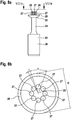
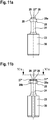
- Fig. 11a to Fig. 11e an embodiment is shown in which the annular surface 17 of the spike hole bottom 8 with its outer line 18 and with its inner line 19 do not form a circular ring, but a somewhat flattened oval or elliptical ring.
- the outer line 18 forms the envelope curve h 2 and the inner line 19 forms the envelope curve h 3 .
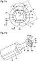
- FIGS 11a to 11e furthermore show an exemplary embodiment in which depressions 16 'or 16 "in the spike hole base 8 are not designed with a circular, but with an elongated contour, in the shape of a ring segment with a length L formed in the direction of extension of the annular surface 17, which is significantly greater than the width b formed perpendicular to the circumferential extension of the annular surface.
- Figures 11a to 11e a further embodiment in which first depressions 16 'are generated by first appropriately shaped pins 27' and second depressions 16 "are generated by second appropriately shaped pins 27", the depressions 16 "having a length L in the circumferential extension direction of the annular surface 17 that is significantly greater than the depressions 16 'and, in an analogous manner, also the pins 27 "have a correspondingly greater extension length than the pins 27'.
- the radially outer section 28 is formed with a circumferential extension section 28a and a flattened circumferential extension section 28b.
- the ring-shaped surface 17 is formed along the extent of the circumferential extension section 28a with its outer line 18 and with its inner line 19 essentially as a concentric ring segment surface and in the circumferential extension section 28b is configured as a linearly extending ring segment surface.
- the wells 16 ′′ are here - as in the representations in Figures 11a to 11e Long hole-shaped depressions 16 ′′ extending along the circumferential direction of extent of the annular surface 17 with an extension length L which is greater than the width b.
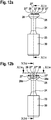
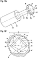
- FIGS Figures 12a to 12f illustrated embodiment a further embodiment is shown which, like that in FIGS Figures 12a to 12f illustrated embodiment is formed, but the annular surface 17 is formed only with three depressions 16 'in the extension region of the annular surface 17 along the extension of the radially outer circumferential extension section 28a and with only one recess 16 "in the circumferential extension section 28b, the recess 16" deeper and is formed with a larger diameter than the recesses 16 '.
- the inner line 19 and the outer line 18 are not shown.
- the inner circumference U 3 of the annular surfaces formed with depressions 16 is formed with (0.15U 1 ) U 3 (0.90 U 1 ).
- the inner circumference U 3 is expediently designed with (0.4U 1 ) U 3 (0.65 U 1 ), as in the exemplary embodiments illustrated and described above.
Landscapes
- Engineering & Computer Science (AREA)
- Mechanical Engineering (AREA)
- Tires In General (AREA)
Claims (10)
- Pneu de véhicule comprenant un profil de bande de roulement et des orifices de pointes (5) destinés à recevoir des pointes (11), qui sont délimités vers l'intérieur dans la direction radiale R du pneu de véhicule respectivement par un fond d'orifice (8), caractérisé en ce que
sur une surface annulaire (17) du fond d'orifice (8) sont agencés, répartis les uns après les autres en une rangée, plusieurs creux (16) respectivement espacés les uns des autres dans la direction d'extension circonférentielle de la surface annulaire (17). - Pneu de véhicule selon les caractéristiques de la revendication 1, dans lequel les creux (16) sont agencés répartis uniformément dans la direction d'extension circonférentielle de la surface annulaire (17).
- Pneu de véhicule selon les caractéristiques de la revendication 1 ou 2, dans lequel les creux (16) sont configurés avec une profondeur identique dans la surface annulaire (17).
- Pneu de véhicule selon les caractéristiques de la revendication 1 ou 2, dans lequel les creux (16) sont configurés avec une profondeur différente dans la surface annulaire (17).
- Pneu de véhicule selon les caractéristiques de l'une quelconque des revendications précédentes, dans lequel les creux (16) de la surface annulaire (17) sont configurés respectivement avec une largeur b, notamment de taille identique, mesurée perpendiculairement à la direction d'extension circonférentielle de la surface annulaire avec 0,2 mm ≤ b ≤ 1,5 mm.
- Pneu de véhicule selon les caractéristiques de l'une quelconque des revendications précédentes, dans lequel les creux (16) de la surface annulaire (17) sont configurés respectivement avec une longueur L identique, mesurée le long de la direction d'extension circonférentielle de la surface annulaire (17).
- Pneu de véhicule selon les caractéristiques de l'une quelconque des revendications précédentes, dans lequel les creux (16) de la surface annulaire (17) s'étendent respectivement sur un angle d'extension circonférentiel α de la surface annulaire (17) avec 5° ≤ α ≤ 120°.
- Pneu de véhicule selon les caractéristiques de l'une quelconque des revendications 1 à 5, dans lequel les creux (16) de la surface annulaire (17) sont configurés avec une longueur L au moins en partie différente, mesurée le long de la direction d'extension circonférentielle de la surface annulaire (17).
- Pneu de véhicule selon les caractéristiques de l'une quelconque des revendications 1 à 5, dans lequel un ou plusieurs des creux (16) de la surface annulaire (17) sont configurés dans le fond d'orifice (8) avec un contour en forme de segment d'anneau.
- Pneu de véhicule selon les caractéristiques de la revendication 8, dans lequel quatre creux (16) en forme de segment d'anneau agencés les uns après les autres, notamment concentriques, sont formés dans le fond d'orifice (8).
Applications Claiming Priority (2)
| Application Number | Priority Date | Filing Date | Title |
|---|---|---|---|
| DE102016221854.9A DE102016221854A1 (de) | 2016-11-08 | 2016-11-08 | Fahrzeugreifen |
| PCT/EP2017/071062 WO2018086775A1 (fr) | 2016-11-08 | 2017-08-22 | Pneumatique de véhicule |
Publications (2)
| Publication Number | Publication Date |
|---|---|
| EP3538384A1 EP3538384A1 (fr) | 2019-09-18 |
| EP3538384B1 true EP3538384B1 (fr) | 2020-10-07 |
Family
ID=59799344
Family Applications (1)
| Application Number | Title | Priority Date | Filing Date |
|---|---|---|---|
| EP17762057.2A Active EP3538384B1 (fr) | 2016-11-08 | 2017-08-22 | Pneumatique de véhicule |
Country Status (3)
| Country | Link |
|---|---|
| EP (1) | EP3538384B1 (fr) |
| DE (1) | DE102016221854A1 (fr) |
| WO (1) | WO2018086775A1 (fr) |
Families Citing this family (1)
| Publication number | Priority date | Publication date | Assignee | Title |
|---|---|---|---|---|
| FI4461571T3 (fi) * | 2023-05-08 | 2025-09-18 | Nokian Renkaat Oyj | Nastarengas ajoneuvoja varten |
Family Cites Families (3)
| Publication number | Priority date | Publication date | Assignee | Title |
|---|---|---|---|---|
| FI46349B (fr) | 1971-08-27 | 1972-11-30 | Patent Holding Ltd | |
| FR2931727B1 (fr) * | 2008-05-29 | 2010-06-11 | Michelin Soc Tech | Crampon pour pneumatique, pourvu d'evidements destines a ameliorer sa tenue dans le pneumatique |
| DE102015219368B4 (de) * | 2014-10-09 | 2021-12-02 | Toyo Tire & Rubber Co., Ltd. | Spike und Spikereifen |
-
2016
- 2016-11-08 DE DE102016221854.9A patent/DE102016221854A1/de not_active Withdrawn
-
2017
- 2017-08-22 EP EP17762057.2A patent/EP3538384B1/fr active Active
- 2017-08-22 WO PCT/EP2017/071062 patent/WO2018086775A1/fr not_active Ceased
Non-Patent Citations (1)
| Title |
|---|
| None * |
Also Published As
| Publication number | Publication date |
|---|---|
| WO2018086775A1 (fr) | 2018-05-17 |
| DE102016221854A1 (de) | 2018-05-09 |
| EP3538384A1 (fr) | 2019-09-18 |
Similar Documents
| Publication | Publication Date | Title |
|---|---|---|
| DE2322357A1 (de) | Spike-bolzen | |
| DE102009044547A1 (de) | Laufstreifenprofil eines Fahrzeugluftreifens | |
| EP0625436B1 (fr) | Bandage pneumatique pour véhicule | |
| EP2311656B1 (fr) | Profil de bande de roulement d'une bande pneumatique de véhicule | |
| DE102008030810A1 (de) | Fahrzeugluftreifen | |
| DE102014225047A1 (de) | Fahrzeugluftreifen | |
| WO2011039030A1 (fr) | Profil de bande de roulement d'un pneumatique de véhicule | |
| DE3335899A1 (de) | Vollreifen aus gummi oder einem analogen material, mit abnehmbarem laufband | |
| EP2644408B1 (fr) | Profil de bande de roulement d'un bandage pneumatique de véhicule | |
| EP2489526B1 (fr) | Profil de bande de roulement d'un bandage pneumatique de véhicule | |
| EP3538384B1 (fr) | Pneumatique de véhicule | |
| EP3619057B1 (fr) | Pneumatique de véhicule | |
| WO2018007039A1 (fr) | Pneumatique de véhicule | |
| DE102019206654A1 (de) | Fahrzeugluftreifen | |
| EP3659827B1 (fr) | Pneumatiques de véhicule comportant un profil de bande de roulement à une contre-dépouille | |
| DE102006031779A1 (de) | Laufstreifenprofil eines Fahrzeugreifens | |
| EP1992505B1 (fr) | Pneus de véhicule | |
| EP3890994B1 (fr) | Profil de bande de roulement d'un pneu de véhicule | |
| DE102011050705A1 (de) | Laufstreifenprofil eines Fahrzeugluftreifens | |
| EP2794298B1 (fr) | Band de roulement d´un pneu | |
| EP2388154B1 (fr) | Profil de bande de roulement d'un bandage pneumatique de véhicule | |
| EP3746314B1 (fr) | Crampon et pneumatic avec des crampons | |
| DE102017212713A1 (de) | Laufstreifenprofil eines Fahrzeugreifens | |
| DE102008029658A1 (de) | Fahrzeugluftreifen | |
| EP3390112B1 (fr) | Pneumatique de véhicule avec crampons |
Legal Events
| Date | Code | Title | Description |
|---|---|---|---|
| STAA | Information on the status of an ep patent application or granted ep patent |
Free format text: STATUS: UNKNOWN |
|
| STAA | Information on the status of an ep patent application or granted ep patent |
Free format text: STATUS: THE INTERNATIONAL PUBLICATION HAS BEEN MADE |
|
| PUAI | Public reference made under article 153(3) epc to a published international application that has entered the european phase |
Free format text: ORIGINAL CODE: 0009012 |
|
| STAA | Information on the status of an ep patent application or granted ep patent |
Free format text: STATUS: REQUEST FOR EXAMINATION WAS MADE |
|
| 17P | Request for examination filed |
Effective date: 20190611 |
|
| AK | Designated contracting states |
Kind code of ref document: A1 Designated state(s): AL AT BE BG CH CY CZ DE DK EE ES FI FR GB GR HR HU IE IS IT LI LT LU LV MC MK MT NL NO PL PT RO RS SE SI SK SM TR |
|
| AX | Request for extension of the european patent |
Extension state: BA ME |
|
| DAV | Request for validation of the european patent (deleted) | ||
| DAX | Request for extension of the european patent (deleted) | ||
| GRAP | Despatch of communication of intention to grant a patent |
Free format text: ORIGINAL CODE: EPIDOSNIGR1 |
|
| STAA | Information on the status of an ep patent application or granted ep patent |
Free format text: STATUS: GRANT OF PATENT IS INTENDED |
|
| INTG | Intention to grant announced |
Effective date: 20200529 |
|
| GRAS | Grant fee paid |
Free format text: ORIGINAL CODE: EPIDOSNIGR3 |
|
| GRAA | (expected) grant |
Free format text: ORIGINAL CODE: 0009210 |
|
| STAA | Information on the status of an ep patent application or granted ep patent |
Free format text: STATUS: THE PATENT HAS BEEN GRANTED |
|
| AK | Designated contracting states |
Kind code of ref document: B1 Designated state(s): AL AT BE BG CH CY CZ DE DK EE ES FI FR GB GR HR HU IE IS IT LI LT LU LV MC MK MT NL NO PL PT RO RS SE SI SK SM TR |
|
| REG | Reference to a national code |
Ref country code: GB Ref legal event code: FG4D Free format text: NOT ENGLISH |
|
| REG | Reference to a national code |
Ref country code: CH Ref legal event code: EP Ref country code: AT Ref legal event code: REF Ref document number: 1320789 Country of ref document: AT Kind code of ref document: T Effective date: 20201015 |
|
| REG | Reference to a national code |
Ref country code: IE Ref legal event code: FG4D Free format text: LANGUAGE OF EP DOCUMENT: GERMAN |
|
| REG | Reference to a national code |
Ref country code: DE Ref legal event code: R096 Ref document number: 502017007662 Country of ref document: DE |
|
| RAP2 | Party data changed (patent owner data changed or rights of a patent transferred) |
Owner name: CONTINENTAL REIFEN DEUTSCHLAND GMBH |
|
| REG | Reference to a national code |
Ref country code: FI Ref legal event code: FGE |
|
| REG | Reference to a national code |
Ref country code: NO Ref legal event code: T2 Effective date: 20201007 |
|
| REG | Reference to a national code |
Ref country code: NL Ref legal event code: MP Effective date: 20201007 |
|
| PG25 | Lapsed in a contracting state [announced via postgrant information from national office to epo] |
Ref country code: PT Free format text: LAPSE BECAUSE OF FAILURE TO SUBMIT A TRANSLATION OF THE DESCRIPTION OR TO PAY THE FEE WITHIN THE PRESCRIBED TIME-LIMIT Effective date: 20210208 Ref country code: RS Free format text: LAPSE BECAUSE OF FAILURE TO SUBMIT A TRANSLATION OF THE DESCRIPTION OR TO PAY THE FEE WITHIN THE PRESCRIBED TIME-LIMIT Effective date: 20201007 Ref country code: GR Free format text: LAPSE BECAUSE OF FAILURE TO SUBMIT A TRANSLATION OF THE DESCRIPTION OR TO PAY THE FEE WITHIN THE PRESCRIBED TIME-LIMIT Effective date: 20210108 |
|
| REG | Reference to a national code |
Ref country code: LT Ref legal event code: MG4D |
|
| PG25 | Lapsed in a contracting state [announced via postgrant information from national office to epo] |
Ref country code: BG Free format text: LAPSE BECAUSE OF FAILURE TO SUBMIT A TRANSLATION OF THE DESCRIPTION OR TO PAY THE FEE WITHIN THE PRESCRIBED TIME-LIMIT Effective date: 20210107 Ref country code: SE Free format text: LAPSE BECAUSE OF FAILURE TO SUBMIT A TRANSLATION OF THE DESCRIPTION OR TO PAY THE FEE WITHIN THE PRESCRIBED TIME-LIMIT Effective date: 20201007 Ref country code: IS Free format text: LAPSE BECAUSE OF FAILURE TO SUBMIT A TRANSLATION OF THE DESCRIPTION OR TO PAY THE FEE WITHIN THE PRESCRIBED TIME-LIMIT Effective date: 20210207 Ref country code: PL Free format text: LAPSE BECAUSE OF FAILURE TO SUBMIT A TRANSLATION OF THE DESCRIPTION OR TO PAY THE FEE WITHIN THE PRESCRIBED TIME-LIMIT Effective date: 20201007 Ref country code: LV Free format text: LAPSE BECAUSE OF FAILURE TO SUBMIT A TRANSLATION OF THE DESCRIPTION OR TO PAY THE FEE WITHIN THE PRESCRIBED TIME-LIMIT Effective date: 20201007 Ref country code: ES Free format text: LAPSE BECAUSE OF FAILURE TO SUBMIT A TRANSLATION OF THE DESCRIPTION OR TO PAY THE FEE WITHIN THE PRESCRIBED TIME-LIMIT Effective date: 20201007 |
|
| PG25 | Lapsed in a contracting state [announced via postgrant information from national office to epo] |
Ref country code: HR Free format text: LAPSE BECAUSE OF FAILURE TO SUBMIT A TRANSLATION OF THE DESCRIPTION OR TO PAY THE FEE WITHIN THE PRESCRIBED TIME-LIMIT Effective date: 20201007 Ref country code: NL Free format text: LAPSE BECAUSE OF FAILURE TO SUBMIT A TRANSLATION OF THE DESCRIPTION OR TO PAY THE FEE WITHIN THE PRESCRIBED TIME-LIMIT Effective date: 20201007 |
|
| REG | Reference to a national code |
Ref country code: DE Ref legal event code: R097 Ref document number: 502017007662 Country of ref document: DE |
|
| PG25 | Lapsed in a contracting state [announced via postgrant information from national office to epo] |
Ref country code: LT Free format text: LAPSE BECAUSE OF FAILURE TO SUBMIT A TRANSLATION OF THE DESCRIPTION OR TO PAY THE FEE WITHIN THE PRESCRIBED TIME-LIMIT Effective date: 20201007 Ref country code: EE Free format text: LAPSE BECAUSE OF FAILURE TO SUBMIT A TRANSLATION OF THE DESCRIPTION OR TO PAY THE FEE WITHIN THE PRESCRIBED TIME-LIMIT Effective date: 20201007 Ref country code: CZ Free format text: LAPSE BECAUSE OF FAILURE TO SUBMIT A TRANSLATION OF THE DESCRIPTION OR TO PAY THE FEE WITHIN THE PRESCRIBED TIME-LIMIT Effective date: 20201007 Ref country code: SM Free format text: LAPSE BECAUSE OF FAILURE TO SUBMIT A TRANSLATION OF THE DESCRIPTION OR TO PAY THE FEE WITHIN THE PRESCRIBED TIME-LIMIT Effective date: 20201007 Ref country code: RO Free format text: LAPSE BECAUSE OF FAILURE TO SUBMIT A TRANSLATION OF THE DESCRIPTION OR TO PAY THE FEE WITHIN THE PRESCRIBED TIME-LIMIT Effective date: 20201007 Ref country code: SK Free format text: LAPSE BECAUSE OF FAILURE TO SUBMIT A TRANSLATION OF THE DESCRIPTION OR TO PAY THE FEE WITHIN THE PRESCRIBED TIME-LIMIT Effective date: 20201007 |
|
| PLBE | No opposition filed within time limit |
Free format text: ORIGINAL CODE: 0009261 |
|
| STAA | Information on the status of an ep patent application or granted ep patent |
Free format text: STATUS: NO OPPOSITION FILED WITHIN TIME LIMIT |
|
| PG25 | Lapsed in a contracting state [announced via postgrant information from national office to epo] |
Ref country code: DK Free format text: LAPSE BECAUSE OF FAILURE TO SUBMIT A TRANSLATION OF THE DESCRIPTION OR TO PAY THE FEE WITHIN THE PRESCRIBED TIME-LIMIT Effective date: 20201007 |
|
| 26N | No opposition filed |
Effective date: 20210708 |
|
| PG25 | Lapsed in a contracting state [announced via postgrant information from national office to epo] |
Ref country code: IT Free format text: LAPSE BECAUSE OF FAILURE TO SUBMIT A TRANSLATION OF THE DESCRIPTION OR TO PAY THE FEE WITHIN THE PRESCRIBED TIME-LIMIT Effective date: 20201007 Ref country code: AL Free format text: LAPSE BECAUSE OF FAILURE TO SUBMIT A TRANSLATION OF THE DESCRIPTION OR TO PAY THE FEE WITHIN THE PRESCRIBED TIME-LIMIT Effective date: 20201007 |
|
| PG25 | Lapsed in a contracting state [announced via postgrant information from national office to epo] |
Ref country code: SI Free format text: LAPSE BECAUSE OF FAILURE TO SUBMIT A TRANSLATION OF THE DESCRIPTION OR TO PAY THE FEE WITHIN THE PRESCRIBED TIME-LIMIT Effective date: 20201007 |
|
| REG | Reference to a national code |
Ref country code: CH Ref legal event code: PL |
|
| PG25 | Lapsed in a contracting state [announced via postgrant information from national office to epo] |
Ref country code: MC Free format text: LAPSE BECAUSE OF FAILURE TO SUBMIT A TRANSLATION OF THE DESCRIPTION OR TO PAY THE FEE WITHIN THE PRESCRIBED TIME-LIMIT Effective date: 20201007 |
|
| REG | Reference to a national code |
Ref country code: BE Ref legal event code: MM Effective date: 20210831 |
|
| GBPC | Gb: european patent ceased through non-payment of renewal fee |
Effective date: 20210822 |
|
| PG25 | Lapsed in a contracting state [announced via postgrant information from national office to epo] |
Ref country code: LI Free format text: LAPSE BECAUSE OF NON-PAYMENT OF DUE FEES Effective date: 20210831 Ref country code: CH Free format text: LAPSE BECAUSE OF NON-PAYMENT OF DUE FEES Effective date: 20210831 |
|
| PG25 | Lapsed in a contracting state [announced via postgrant information from national office to epo] |
Ref country code: IS Free format text: LAPSE BECAUSE OF FAILURE TO SUBMIT A TRANSLATION OF THE DESCRIPTION OR TO PAY THE FEE WITHIN THE PRESCRIBED TIME-LIMIT Effective date: 20210207 Ref country code: LU Free format text: LAPSE BECAUSE OF NON-PAYMENT OF DUE FEES Effective date: 20210822 |
|
| PG25 | Lapsed in a contracting state [announced via postgrant information from national office to epo] |
Ref country code: IE Free format text: LAPSE BECAUSE OF NON-PAYMENT OF DUE FEES Effective date: 20210822 Ref country code: GB Free format text: LAPSE BECAUSE OF NON-PAYMENT OF DUE FEES Effective date: 20210822 Ref country code: FR Free format text: LAPSE BECAUSE OF NON-PAYMENT OF DUE FEES Effective date: 20210831 Ref country code: BE Free format text: LAPSE BECAUSE OF NON-PAYMENT OF DUE FEES Effective date: 20210831 |
|
| PG25 | Lapsed in a contracting state [announced via postgrant information from national office to epo] |
Ref country code: CY Free format text: LAPSE BECAUSE OF FAILURE TO SUBMIT A TRANSLATION OF THE DESCRIPTION OR TO PAY THE FEE WITHIN THE PRESCRIBED TIME-LIMIT Effective date: 20201007 |
|
| PG25 | Lapsed in a contracting state [announced via postgrant information from national office to epo] |
Ref country code: HU Free format text: LAPSE BECAUSE OF FAILURE TO SUBMIT A TRANSLATION OF THE DESCRIPTION OR TO PAY THE FEE WITHIN THE PRESCRIBED TIME-LIMIT; INVALID AB INITIO Effective date: 20170822 |
|
| REG | Reference to a national code |
Ref country code: AT Ref legal event code: MM01 Ref document number: 1320789 Country of ref document: AT Kind code of ref document: T Effective date: 20220822 |
|
| PG25 | Lapsed in a contracting state [announced via postgrant information from national office to epo] |
Ref country code: AT Free format text: LAPSE BECAUSE OF NON-PAYMENT OF DUE FEES Effective date: 20220822 |
|
| REG | Reference to a national code |
Ref country code: DE Ref legal event code: R081 Ref document number: 502017007662 Country of ref document: DE Owner name: CONTINENTAL REIFEN DEUTSCHLAND GMBH, DE Free format text: FORMER OWNER: CONTINENTAL REIFEN DEUTSCHLAND GMBH, 30165 HANNOVER, DE |
|
| PG25 | Lapsed in a contracting state [announced via postgrant information from national office to epo] |
Ref country code: MK Free format text: LAPSE BECAUSE OF FAILURE TO SUBMIT A TRANSLATION OF THE DESCRIPTION OR TO PAY THE FEE WITHIN THE PRESCRIBED TIME-LIMIT Effective date: 20201007 |
|
| PG25 | Lapsed in a contracting state [announced via postgrant information from national office to epo] |
Ref country code: MT Free format text: LAPSE BECAUSE OF FAILURE TO SUBMIT A TRANSLATION OF THE DESCRIPTION OR TO PAY THE FEE WITHIN THE PRESCRIBED TIME-LIMIT Effective date: 20201007 |
|
| PGFP | Annual fee paid to national office [announced via postgrant information from national office to epo] |
Ref country code: FI Payment date: 20240821 Year of fee payment: 8 |
|
| PGFP | Annual fee paid to national office [announced via postgrant information from national office to epo] |
Ref country code: DE Payment date: 20250831 Year of fee payment: 9 |
|
| PGFP | Annual fee paid to national office [announced via postgrant information from national office to epo] |
Ref country code: NO Payment date: 20250826 Year of fee payment: 9 |
|
| PG25 | Lapsed in a contracting state [announced via postgrant information from national office to epo] |
Ref country code: TR Free format text: LAPSE BECAUSE OF FAILURE TO SUBMIT A TRANSLATION OF THE DESCRIPTION OR TO PAY THE FEE WITHIN THE PRESCRIBED TIME-LIMIT Effective date: 20201007 |
|
| PG25 | Lapsed in a contracting state [announced via postgrant information from national office to epo] |
Ref country code: FI Free format text: LAPSE BECAUSE OF NON-PAYMENT OF DUE FEES Effective date: 20250822 |