EP3538430B1 - Belüftungssystem - Google Patents
Belüftungssystem Download PDFInfo
- Publication number
- EP3538430B1 EP3538430B1 EP16816385.5A EP16816385A EP3538430B1 EP 3538430 B1 EP3538430 B1 EP 3538430B1 EP 16816385 A EP16816385 A EP 16816385A EP 3538430 B1 EP3538430 B1 EP 3538430B1
- Authority
- EP
- European Patent Office
- Prior art keywords
- capsule
- underwater environment
- duct
- gas
- pressure
- Prior art date
- Legal status (The legal status is an assumption and is not a legal conclusion. Google has not performed a legal analysis and makes no representation as to the accuracy of the status listed.)
- Active
Links
Images

Classifications
-
- B—PERFORMING OPERATIONS; TRANSPORTING
- B63—SHIPS OR OTHER WATERBORNE VESSELS; RELATED EQUIPMENT
- B63G—OFFENSIVE OR DEFENSIVE ARRANGEMENTS ON VESSELS; MINE-LAYING; MINE-SWEEPING; SUBMARINES; AIRCRAFT CARRIERS
- B63G8/00—Underwater vessels, e.g. submarines; Equipment specially adapted therefor
- B63G8/36—Adaptations of ventilation, e.g. schnorkels, cooling, heating, or air-conditioning
-
- B—PERFORMING OPERATIONS; TRANSPORTING
- B63—SHIPS OR OTHER WATERBORNE VESSELS; RELATED EQUIPMENT
- B63G—OFFENSIVE OR DEFENSIVE ARRANGEMENTS ON VESSELS; MINE-LAYING; MINE-SWEEPING; SUBMARINES; AIRCRAFT CARRIERS
- B63G8/00—Underwater vessels, e.g. submarines; Equipment specially adapted therefor
- B63G8/40—Rescue equipment for personnel
Definitions
- the present invention relates to a system for emergency ventilation of an underwater environment and a method for the emergency ventilation of an underwater environment.
- a rescue vessel (or a platform) is usually used equipped with a large compressed air storage system.
- the underwater environment is connected to two ducts, one is for transferring the pressurized air from this storage system to the underwater environment, and the other to bring the exhaust air back to the surface.
- the air that is pushed must be with high pressure, since it has to reach the underwater environment and come back to surface (to facilitate this air movement, there are some pumps at the end of the second duct).
- the recovery activities as described above have certain disadvantages including: the necessity to have huge and expensive devices to direct the pressurized air and (most of all) to recovery and allow air to escape in surface; and a relevant pressure increase inside the underwater environment with some health risks for the operators inside the underwater environment and the necessity to keep them in a decompression chamber in way to reduce embolism risks, once they are recovered.
- EP2301839A2 discloses a ventilation device for a submerged damaged submarine, which device has a connection for a supply line leading to a water surface, and a pressure regulator arranged in a conducting path from the connection of the supply line to a ventilation connection of a submerged damaged submarine.
- the aim of the present invention is to provide an emergency ventilation system of an underwater environment and a method for the emergency ventilation of an underwater environment, which make it possible to overcome, at least partially, the inconvenience of this type of activity and is at the same time cost-effective and easy to realize.
- an emergency ventilation system for an underwater environment and a method for the emergency ventilation of an underwater environment are provided, as recited in the independent claims below, and, preferably, in any one of the claims depending directly or indirectly on the aforementioned independent claims.
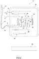
- 1 indicates a system for the emergency ventilation of an underwater environment 2 (dry) as a whole.
- the underwater environment 2 is a submarine and/or a welding habitat.
- the system 1 comprises a supply device 3 for providing a gas containing oxygen, in particular air; a capsule 4 adapted to be immersed in water (in particular, to a depth of at least 60 meters - below the surface 5); a duct 6 to fluidically connect the power supply device 3 to the capsule 4 so that the capsule 4 uploads the gas coming from the supply device 3.
- the capsule 4 is adapted to be immersed in water to a depth of at least 100 meters (below the surface 5 of water).
- the system 1 comprises also a duct 7 to fluidically connect the capsule 4 to the underwater environment 2 so as to allow the passage of gas from the capsule 4 to the underwater environment 2 itself; a duct 8 to fluidically connect the underwater environment 2 to the capsule 4 so that it allows the passage of the gas from the underwater environment 2 to the capsule 4; and one compressor 9 for the exhaust of the gas arrived inside the capsule 4 through the duct 8 from the underwater environment 2 into the water at a depth of at least 60 meters (under the surface 5 of the water itself).
- the compressor 9 is adapted to unload the gas inside water at a depth of at least 100 meters (under the surface 5 of the water itself).
- the compressor 9 is fluidically connected to duct 8.
- the capsule 4 includes the compressor 9.
- the duct 6 is extended from the supplying device 3 to the capsule 4; the duct 7 and 8 protrude from capsule 4 and are arranged to bond at the underwater environment 2.
- the supplying device 3 is suitable to be (and during the use is) placed outside of the water in an environment substantially dry.
- the supplying device 3 is designed to supply gas to the capsule 4 at a pressure that is higher than atmospheric pressure (for example, at a pressure up to 3 bar).
- the system 1 (more precisely, the capsule 4) comprises an adjustment device 10 to adjust the pressure of the gas that is supplied to the underwater environment 2. More particularly, the adjustment device 10 is designed to adjust the pressure of the gas inside the duct 7, so that the gas reaches the underwater environment 2 at a pressure that is lower than a first given pressure (in some cases of 3 bar absolute - corresponding to 30 5 Pa). More precisely, the adjustment device 10 is suitable to adjust the pressure of the gas inside the duct 7, so that the gas reaches the underwater environment 2 at a pressure that is lower than a first given pressure of 2 bar - corresponding to 20 5 Pa.
- a first given pressure in some cases of 3 bar absolute - corresponding to 30 5 Pa.
- the adjustment device 10 is suitable to adjust the pressure of the gas inside the duct 7, so that the gas reaches the underwater environment 2 at a pressure that is lower than a first given pressure of 2 bar - corresponding to 20 5 Pa.
- higher-pressure levels up to 6 bar, may be necessary to maintain the ventilation flow whenever pressure increases take place due to failures inside the underwater environment 2.
- the adjustment device 10 comprises (is) a valve (in some cases a ball valve) and/or a membrane mechanism. Due to the adjustment device 10 the risk of excessive pressure increase inside the underwater environment 2 is reduced.
- the system 1 (more precisely, the capsule 4) comprises a control unit 11.
- control unit 11 is designed to adjust the operation of at least one between the supplying device 3 and compressor 9 (and/or the heat exchanger 9'), so as to keep the concentration of the carbon dioxide (and/or other specific gases) and/or oxygen (and/or the temperature) (and/or the ventilation) inside the underwater environment 2 within a given interval (to allow the air inside the underwater environment 2 to be breathable for the operators located inside it).
- control unit 11 will operate the supplying device 3 and the compressor 9 in such a way to increase the air flow (coming from the surface) through the capsule 4.
- the system 1 comprises a sensor 12 for the detection of the carbon dioxide and/or oxygen concentration inside the gas coming from the underwater environment 2 (particularly, through the duct 8).
- the system 1 comprises a connection 13 for a detection system, which is arranged in the underwater environment 2 and is designed to detect the concentration of carbon dioxide (and/or of other specific gases ) and/or oxygen (and/or temperature ) in the underwater environment 2 itself.
- the control unit 11 is connected to the sensor 12 and/or to the connection 13 and is adapted to adjust the actuation of at least one of the power supply device 3 and the compressor 9 (and/or the heat exchanger 9 ') according to what is detected by the sensor 12 and/or by the detection system (of the underwater environment 2), respectively.
- the system 1 (in particular, the capsule 4) includes a heat exchanger 9 in order to heat the gases to be fed in the underwater environment 2 through the duct 7.
- the heat exchanger 9' is connected to the compressor 9 so that the heat produced by the compressor 9 itself can be used.
- the system 1 (in particular, the capsule 4) comprises an adjusting device 14 to allow the passage of gas from the underwater environment 2 to the compressor 9 through the duct 8 when the pressure in the duct 8 is higher than a reference pressure (in particular, 1 bar absolute, more particularly, not more than 1 bar in addition to the original pressure of the underwater environment 2).
- a reference pressure in particular, 1 bar absolute, more particularly, not more than 1 bar in addition to the original pressure of the underwater environment 2).
- the adjusting device 14 comprises (is) a valve (in some cases a ball valve) and/or a diaphragm mechanism. Thanks to the adjusting device 14 it reduces the risk that the pressure inside the underwater environment 2 decreases excessively.
- the system 1 (in particular, the capsule 4) comprises a tank 15 for fluidically connecting the duct 8 and the compressor 9.
- the duct 8 goes from the reservoir 15 to the underwater environment 2.
- the tank 15 fluidically connects (is located between) the adjusting device 14 and the compressor 9.
- the control unit 11 is adapted to activate the compressor 9 so as to maintain the pressure inside the tank 15 in a given range, in particular compatible with the performance of the compressor 9 (more specifically, from 1 bar to 2 bar absolute).
- the capsule 4 comprises a pressure sensor 16 for measuring the pressure inside the tank 15. More particularly, the control unit 11 activates the compressor 9 as a function what is detected by the pressure sensor 16.
- a valve (ball valve) is located between the sensor 16 and the tank 15.
- the system 1 includes a vessel or a platform 17, on which the power supply device 3 is located.
- the power supply device 3 comprises a pump (and a tank/gas storage) which enables the gas (air) to be pushed from above the water surface 5 to the capsule 4.
- the system 1 also includes an electrical connection 18 for supplying electrical energy to the capsule 4 (and its components) from outside (in particular, from the platform 17) . More precisely, the electrical connection 18 is adapted to supply the control unit 11, the compressor 9 and the sensors 12 and 16.
- the system 1 also comprises a link 19 to allow the transfer of information between the boat or platform 17 and the control unit 11.
- the system 1 comprises a ballast 20, which, in particular, maintains the capsule 4 at the required depth (maintaining its own stability in water).
- system 1 includes an auxiliary umbilical cable 21, which is adapted to bear the weight of the capsule 4 (and possibly also the ballast 20) in the air and the related dynamic loads during the launching.
- the electrical connection 18, the link 19 and in the duct 6 are part of or connected to (inserted into) the umbilical cable 21.
- the umbilical cable 21 connects the vessel or platform 17 to the capsule 4.
- the system 1 also includes a launch and recovery unit 22, which is suitable for moving (for example, bring it in water and / or lift it) the capsule 4 by acting on the umbilical cable 21.
- a launch and recovery unit 22 is suitable for moving (for example, bring it in water and / or lift it) the capsule 4 by acting on the umbilical cable 21.
- the capsule 4 includes an exhaust outlet 23, adapted to allow the exit of the gas (exhausted) in the water from the capsule 4.
- the compressor 9 is designed to convey the gas through the exhaust outlet 23.
- a one-way valve 24 (to prevent water coming from the exhaust outlet 23 reaches the compressor 9) is located between the exhaust outlet 23 and the compressor 9.
- the capsule 4 comprises a filter 25 also, which is located between the duct 8 (more specifically, the adjusting device 10; even more precisely, the tank 15) and the compressor 9. The filter 25 helps to improve the mechanical protection of the compressor 9.
- the capsule 4 also comprises a vacuum breaker valve 26, which is located downstream of the underwater environment 2 in order to avoid creating an excessive depression in the underwater environment 2 itself.
- the vacuum breaker valve 26 is located between the duct 8 and the compressor 9.
- a one-way valve 27 which allows the passage of gas only from the duct 6 to the capsule 4 and not vice versa is also provided. More precisely, the one-way valve 27 is placed between the duct 6 and the adjusting device 10.
- the capsule 4 comprises a casing 28 (typically of metal), which is resistant to the external pressure at high depth and encloses the various further components of the capsule 4, for example: the adjustment devices 10 and 14, the unit control 11, the sensors 12 and 16 and the tank 15 (and, possibly, the one-way valves 24 and 27, the vacuum breaker valve 26 and the filter 25).
- the adjustment devices 10 and 14 the unit control 11, the sensors 12 and 16 and the tank 15 (and, possibly, the one-way valves 24 and 27, the vacuum breaker valve 26 and the filter 25).
- the capsule 4 can be composed of two or more separate groups each one provided with its own casing 28.
- a vent 29 is also provided to allow the correct emptying of the tank 15 .
- a valve ball valve
- the capsule 4 In operation, after the launch from the surface, the capsule 4 reaches the depth required (in particular, a depth similar to the underwater environment depth 2 where it operates).
- the capsule 4 (more precisely, the ducts 7 and 8 - and potentially the connection 13) is connected to the underwater environment 2, for example by means of a ROV, through an underwater environment 2 emergency connection 30.
- the power supply device 3 and the compressor 9 are actuated to allow the supply of gas (fresh air) from above the surface 5 to the capsule 4 and from the capsule 4 to the underwater environment 2, and the gas (exhaust air) from the underwater environment 2 to the compressor 9 and from the compressor 9 to the water (through the exhaust outlet 23).
- system 1 in accordance with the present invention has considerable advantages over known systems.
- the system 1 according to the present invention is relatively simple and cost-effective (especially because it does not require any equipment to transfer and vent the exhaust air to the surface) and less harmful and dangerous for the health of the operators present in the underwater environment 2 (you can keep relatively low pressures within the underwater environment 2).
- a method for the emergency ventilation of an underwater environment 2 is provided with a system as described above, and comprising: a first supplying step, during which the gas is fed from the supply device 3 to the capsule 4 immersed in water at a pressure higher than the atmospheric pressure; a second supplying step, during which the gas is conveyed from the capsule 4 immersed in water to the underwater environment 2 through the duct 7; a recovery step, which is at least partly subsequent to the second supplying step and during which the gas is brought from the underwater environment 2 to the capsule 4 immersed in the water through the duct 8; and a draining step, which is at least partially after the recovery step and during which the gas coming from the underwater environment 2 and arriving to the capsule 4, which is immersed in the water, is discharged into the water.
- the capsule 4 is maintained immersed in water at a distance of at most 40 meters from the underwater environment 2.
- the underwater environment 2 is at a depth of 60 (in particular, from 100) to 700 meters (from the surface 5).
- the gas pressure coming from the supply device 3 is maintained within a given range in the area of the capsule 4, in particular proportional to the depth of intervention (more particularly between 2 bar absolute and a higher value due to the increase in pressure that makes it possible to overcome the pressure losses of the flow line, according to the depth of intervention - 70 bar absolute for example).
- the method also comprises a pressure regulation step, during which, in the area of the capsule 4, the gas pressure (from the capsule 4 itself) towards the underwater environment 2 is maintained (flow rate) within a given range.
- the gas pressure (coming from the supplying device 3) is reduced.
- the gas is conveyed from the capsule 4, which is immersed in water, to the underwater environment 2 at a pressure within the given range.
- the pressure of the gas conveyed from the capsule 4 to the underwater environment 2 during the second supply step is less than the pressure of the gas supplied to the capsule 4 during the first supply step.
- the given range is from 1 bar absolute to 3 bar absolute (more particularly, to 2 bar).
- a capsule 4 as described above is provided.
- a use of the system 1 and/or of the capsule 4 for a emergency recovery intervention of an underwater environment 2 is provided (such an underwater environment 2 is as described above).
- the use provides to follow a method as described above.
Landscapes
- Engineering & Computer Science (AREA)
- Mechanical Engineering (AREA)
- Aviation & Aerospace Engineering (AREA)
- Jet Pumps And Other Pumps (AREA)
- Accommodation For Nursing Or Treatment Tables (AREA)
- Filling Or Discharging Of Gas Storage Vessels (AREA)
Claims (14)
- System zur Notbelüftung einer (trockenen) Unterwasserumgebung (2); wobei das System (1) Folgendes umfasst: eine Zuführvorrichtung (3) zum Zuführen eines sauerstoffhaltigen Gases, insbesondere Luft; eine Kapsel (4), die so gestaltet ist, dass sie bis zu einer Tiefe von mindestens 60 Metern in Wasser eingetaucht wird; einen ersten Kanal (6) zur Fluidverbindung der Zuführvorrichtung (3) mit der Kapsel (4), derart dass das Gas, das von der Zuführvorrichtung (3) kommt, zur Kapsel (4) gelangen kann; einen zweiten Kanal (7) zur Fluidverbindung der Kapsel (4) mit der Unterwasserumgebung (2), derart dass es dem Gas erlaubt wird, von der Kapsel (4) zur Unterwasserumgebung (2) zu strömen; einen dritten Kanal (8) zur Fluidverbindung der Unterwasserumgebung (2) mit der Kapsel (4), derart dass es dem Gas erlaubt wird, von der Unterwasserumgebung (2) zur Kapsel (4) zu strömen; und einen Verdichter (9) zum Ablassen des Gases, das von der Unterwasserumgebung (2) durch den dritten Kanal (9) an der Kapsel (4) eintrifft, in das Wasser bei einer Tiefe von mindestens 60 Metern; wobei der Verdichter (9) in Fluidverbindung mit dem dritten Kanal (8) steht; dadurch gekennzeichnet, dass das System (1) ferner Folgendes umfasst: einen Tank (15) zur Fluidverbindung des dritten Kanals (8) und des Verdichters (9); eine Steuereinheit (11) zum Betätigen des Verdichters (9), derart dass der Druck im Inneren des Tanks (15) innerhalb eines gegebenen Intervalls gehalten wird; und einen Ballast (20).
- System nach Anspruch 1, wobei die Zuführvorrichtung (3) so gestaltet ist, dass sie das Gas zur Kapsel (4) bei einem Druck zuführt, der höher ist als der Atmosphärendruck.
- System nach Anspruch 1 oder 2 und das eine erste Anpassungsvorrichtung (10) zum Anpassen des Drucks des Gases umfasst, das der Unterwasserumgebung (2), insbesondere durch den zweiten Kanal (7), zugeführt wird, derart dass das Gas die Unterwasserumgebung (2) bei einem Druck erreicht, der niedriger als ein erster gegebener Druck ist.
- System nach Anspruch 3, wobei der erste gegebene Druck 2 Bar (205 Pa) beträgt.
- System nach einem der vorhergehenden Ansprüche und das eine Steuereinheit (11) umfasst, die so gestaltet ist, dass sie den Betrieb von mindestens einem von der Zuführvorrichtung (3) und/oder dem Verdichter (9) anpasst, derart dass die Konzentration von Kohlendioxid und/oder Sauerstoff im Inneren der Unterwasserumgebung (2) innerhalb eines gegebenen Intervalls gehalten wird.
- System nach einem der vorhergehenden Ansprüche und das mindestens eines von einem Sensor (12) zum Detektieren der Konzentration von Kohlendioxid und/oder Sauerstoff im Gas, das von der Unterwasserumgebung (2) (insbesondere durch den dritten Kanal) kommt, und/oder einer Verbindung (13) für ein Detektionssystem umfasst, das in der Unterwasserumgebung (2) angeordnet ist und so gestaltet ist, dass es die Konzentration von Kohlendioxid und/oder Sauerstoff im Gas, das von der Unterwasserumgebung (2) (insbesondere durch den dritten Kanal) kommt, detektiert.
- System nach einem der vorhergehenden Ansprüche, wobei die Kapsel (4) mindestens einen Wärmetauscher (9') zum Erwärmen des der Unterwasserumgebung (2) durch den zweiten Kanal (7) zuzuführenden Gases umfasst; wobei der Wärmetauscher (9') insbesondere derart mit dem Verdichter (9) verbunden ist, dass er die vom Verdichter (9) selbst erzeugte Wärme nutzt.
- System nach einem der vorhergehenden Ansprüche und das eine zweite Anpassungsvorrichtung (14) umfasst, um das Strömen von Gas von der Unterwasserumgebung (2) zum Verdichter (9) durch den dritten Kanal (8) zu ermöglichen, wenn der Druck im dritten Kanal (8) einen Bezugsdruck überschreitet.
- System nach einem der vorhergehenden Ansprüche, wobei der dritte Kanal (8) sich vom Tank (9) zur Unterwasserumgebung (2) erstreckt.
- System nach einem der vorhergehenden Ansprüche, wobei der Ballast (20) so ausgestaltet ist, dass er die Kapsel (4) in der erforderlichen Tiefe hält, wobei ihre Stabilität in Wasser aufrechterhalten wird.
- System nach einem der vorhergehenden Ansprüche, wobei der erste Kanal (6) sich von der Zuführvorrichtung (3) zur Kapsel (4) erstreckt; der zweite Kanal bei der Kapsel (4) beginnt und so gestaltet ist, dass er zur Unterwasserumgebung (2) gelangt.
- Verfahren zur Notbelüftung einer (trockenen) Unterwasserumgebung (2) mit einem Belüftungssystem (1) nach einem der vorhergehenden Ansprüche und das umfasst:
einen ersten Zuführungsschritt, während dem das Gas von der Zuführungsvorrichtung (3) zur in Wasser eingetauchten Kapsel (4) bei einem Druck zugeführt wird, der höher als Atmosphärendruck ist; einen zweiten Zuführungsschritt, während dem das Gas von der in Wasser eingetauchten Kapsel (4) durch den zweiten Kanal (7) zur Unterwasserumgebung (2) befördert wird; einen Rückgewinnungsschritt, der zumindest teilweise nach dem zweiten Zuführungsschritt stattfindet und während dem Gas von der Unterwasserumgebung (2) durch den dritten Kanal (8) zur in Wasser eingetauchten Kapsel (4) gebracht wird; und einen Ablassschritt, der zumindest teilweise nach dem Rückgewinnungsschritt stattfindet und während dem das Gas, das von der Unterwasserumgebung (2) kommt und die in Wasser eingetauchte Kapsel (4) erreicht hat, in das Wasser abgelassen wird. - Verfahren nach Anspruch 12, wobei während des ersten und des zweiten Zuführungsschritts, des Rückgewinnungsschritts und des Ablassschritts die Kapsel (4) in Wasser in einem Abstand von höchstens 40 Metern von der Unterwasserumgebung eingetaucht gehalten wird.
- Verfahren nach Anspruch 12 oder 13 und das einen Druckanpassungsschritt umfasst, während dem im Bereich der Kapsel (4) der Druck des zur Unterwasserumgebung (2) gerichteten Gases innerhalb eines gegebenen Intervalls gehalten wird.
Applications Claiming Priority (1)
| Application Number | Priority Date | Filing Date | Title |
|---|---|---|---|
| PCT/IB2016/056773 WO2018087580A1 (en) | 2016-11-10 | 2016-11-10 | Ventilation system |
Publications (2)
| Publication Number | Publication Date |
|---|---|
| EP3538430A1 EP3538430A1 (de) | 2019-09-18 |
| EP3538430B1 true EP3538430B1 (de) | 2022-01-12 |
Family
ID=57590730
Family Applications (1)
| Application Number | Title | Priority Date | Filing Date |
|---|---|---|---|
| EP16816385.5A Active EP3538430B1 (de) | 2016-11-10 | 2016-11-10 | Belüftungssystem |
Country Status (3)
| Country | Link |
|---|---|
| US (1) | US10780962B2 (de) |
| EP (1) | EP3538430B1 (de) |
| WO (1) | WO2018087580A1 (de) |
Families Citing this family (1)
| Publication number | Priority date | Publication date | Assignee | Title |
|---|---|---|---|---|
| CN114013609B (zh) * | 2021-11-09 | 2023-03-24 | 烟台宏远载人压力舱工程技术研究院有限公司 | 一种拖拽式深海通风设备 |
Citations (1)
| Publication number | Priority date | Publication date | Assignee | Title |
|---|---|---|---|---|
| EP2301839A2 (de) * | 2009-09-25 | 2011-03-30 | Howaldtswerke-Deutsche Werft GmbH | Belüftungsvorrichtung für ein getaucht havariertes Unterseeboot |
Family Cites Families (7)
| Publication number | Priority date | Publication date | Assignee | Title |
|---|---|---|---|---|
| FR384644A (fr) | 1907-02-09 | 1908-04-15 | Adolphe Beline | Appareil pour le sauvetage des équipages de sous-marins coulés |
| FR427253A (fr) | 1911-02-24 | 1911-07-31 | Gustave Henri Tremolieres | Procédé et dispositif pour le sauvetage du personnel d'un sous-marin coulé |
| GB2300835B (en) | 1995-05-19 | 1999-02-03 | James Ralph Pardoe | Method and apparatus for raising a sunken object |
| US20120318188A1 (en) * | 2010-03-01 | 2012-12-20 | Edison Thurman Hudson | Autonomous Underwater Vehicle |
| US9031733B1 (en) * | 2013-02-15 | 2015-05-12 | The United States Of America As Represented By The Secretary Of The Navy | Casualty monitoring system for autonomous vehicle |
| NO3136728T3 (de) * | 2014-06-30 | 2018-07-28 | ||
| EP3002208B1 (de) * | 2014-10-03 | 2018-12-05 | Calzoni S.r.l. | Verbesserte Luftansaugvorrichtung. |
-
2016
- 2016-11-10 EP EP16816385.5A patent/EP3538430B1/de active Active
- 2016-11-10 WO PCT/IB2016/056773 patent/WO2018087580A1/en not_active Ceased
- 2016-11-10 US US16/348,788 patent/US10780962B2/en active Active
Patent Citations (1)
| Publication number | Priority date | Publication date | Assignee | Title |
|---|---|---|---|---|
| EP2301839A2 (de) * | 2009-09-25 | 2011-03-30 | Howaldtswerke-Deutsche Werft GmbH | Belüftungsvorrichtung für ein getaucht havariertes Unterseeboot |
Also Published As
| Publication number | Publication date |
|---|---|
| US10780962B2 (en) | 2020-09-22 |
| WO2018087580A1 (en) | 2018-05-17 |
| US20190291834A1 (en) | 2019-09-26 |
| EP3538430A1 (de) | 2019-09-18 |
Similar Documents
| Publication | Publication Date | Title |
|---|---|---|
| FI2585178T3 (fi) | Erittäin typpipitoinen ja muuta inerttikaasua sisältävä korroosiosuoja märkäputkipalontorjuntajärjestelmässä | |
| KR101805495B1 (ko) | 가스 공급용 이중 배관을 통한 공기순환 시스템 및 그에 의한 공기순환 방법 | |
| WO2011056580A3 (en) | Controlled discharge gas vent and method of reducing corrosion in a dry fire protection sprinkler system | |
| CN110861749B (zh) | 一种船舶甲醇舱柜结构及其使用方法 | |
| EP2854956B1 (de) | Elektrisch betriebene gasentlüftungen für brandschutz-sprinklersysteme und entsprechende verfahren | |
| US10780962B2 (en) | Ventilation system | |
| KR102578637B1 (ko) | 압력 불균형으로부터 보호되는 연료 전지 | |
| KR101805496B1 (ko) | 가스 공급용 이중 배관을 통한 공기순환 시스템 및 그에 의한 공기순환 방법 | |
| EP3006813B1 (de) | Verfahren zur herstellung eines systems zur instandhaltung | |
| EP3632510A3 (de) | Druckinertisierungssystem | |
| KR102742723B1 (ko) | 수중에 위치된 프로펠러 샤프트를 밀봉하는 방법 및 장치 | |
| KR20130053355A (ko) | 잠수함 기관실의 소화설비 | |
| US20100078076A1 (en) | device for an inert gas installation on a floating vessel | |
| US9527561B1 (en) | Underwater gas pressure regulation system | |
| KR101106703B1 (ko) | 가압가스 누설에 의한 누설 압력상승 방지밸브를 장착한 액화가스 공급 시스템 | |
| SE526233C2 (sv) | System för att förse en dykare med andningsgas | |
| KR101572253B1 (ko) | 잠수상태의 피해를 입은 잠수함을 위한 환기 장치 | |
| IT201600113694A1 (it) | Sistema per la ventilazione | |
| US10683071B2 (en) | Submerged compartment fluid transfer system | |
| NO326747B1 (no) | Anordning og fremgangsmåte for å forhindre inntrenging av sjøvann i en kompressormodul under nedsenking til eller opphenting fra sjøbunnen | |
| RU2330783C2 (ru) | Устройство вентиляции отсеков аварийной подводной лодки, лежащей на грунте | |
| CN204895809U (zh) | 一种船仓进水可供呼吸上浮的救生装置 | |
| KR20170058137A (ko) | 소화장치 | |
| JP2014005963A (ja) | ドレン回収システム | |
| CN111452943A (zh) | 海洋核动力平台核区透气系统 |
Legal Events
| Date | Code | Title | Description |
|---|---|---|---|
| STAA | Information on the status of an ep patent application or granted ep patent |
Free format text: STATUS: UNKNOWN |
|
| STAA | Information on the status of an ep patent application or granted ep patent |
Free format text: STATUS: THE INTERNATIONAL PUBLICATION HAS BEEN MADE |
|
| PUAI | Public reference made under article 153(3) epc to a published international application that has entered the european phase |
Free format text: ORIGINAL CODE: 0009012 |
|
| STAA | Information on the status of an ep patent application or granted ep patent |
Free format text: STATUS: REQUEST FOR EXAMINATION WAS MADE |
|
| 17P | Request for examination filed |
Effective date: 20190510 |
|
| AK | Designated contracting states |
Kind code of ref document: A1 Designated state(s): AL AT BE BG CH CY CZ DE DK EE ES FI FR GB GR HR HU IE IS IT LI LT LU LV MC MK MT NL NO PL PT RO RS SE SI SK SM TR |
|
| AX | Request for extension of the european patent |
Extension state: BA ME |
|
| DAV | Request for validation of the european patent (deleted) | ||
| DAX | Request for extension of the european patent (deleted) | ||
| STAA | Information on the status of an ep patent application or granted ep patent |
Free format text: STATUS: EXAMINATION IS IN PROGRESS |
|
| 17Q | First examination report despatched |
Effective date: 20200306 |
|
| GRAP | Despatch of communication of intention to grant a patent |
Free format text: ORIGINAL CODE: EPIDOSNIGR1 |
|
| STAA | Information on the status of an ep patent application or granted ep patent |
Free format text: STATUS: GRANT OF PATENT IS INTENDED |
|
| INTG | Intention to grant announced |
Effective date: 20210806 |
|
| GRAS | Grant fee paid |
Free format text: ORIGINAL CODE: EPIDOSNIGR3 |
|
| GRAA | (expected) grant |
Free format text: ORIGINAL CODE: 0009210 |
|
| STAA | Information on the status of an ep patent application or granted ep patent |
Free format text: STATUS: THE PATENT HAS BEEN GRANTED |
|
| AK | Designated contracting states |
Kind code of ref document: B1 Designated state(s): AL AT BE BG CH CY CZ DE DK EE ES FI FR GB GR HR HU IE IS IT LI LT LU LV MC MK MT NL NO PL PT RO RS SE SI SK SM TR |
|
| REG | Reference to a national code |
Ref country code: GB Ref legal event code: FG4D |
|
| REG | Reference to a national code |
Ref country code: CH Ref legal event code: EP |
|
| REG | Reference to a national code |
Ref country code: DE Ref legal event code: R096 Ref document number: 602016068367 Country of ref document: DE |
|
| REG | Reference to a national code |
Ref country code: IE Ref legal event code: FG4D |
|
| REG | Reference to a national code |
Ref country code: AT Ref legal event code: REF Ref document number: 1462203 Country of ref document: AT Kind code of ref document: T Effective date: 20220215 |
|
| REG | Reference to a national code |
Ref country code: LT Ref legal event code: MG9D |
|
| REG | Reference to a national code |
Ref country code: NL Ref legal event code: MP Effective date: 20220112 |
|
| REG | Reference to a national code |
Ref country code: AT Ref legal event code: MK05 Ref document number: 1462203 Country of ref document: AT Kind code of ref document: T Effective date: 20220112 |
|
| PG25 | Lapsed in a contracting state [announced via postgrant information from national office to epo] |
Ref country code: NL Free format text: LAPSE BECAUSE OF FAILURE TO SUBMIT A TRANSLATION OF THE DESCRIPTION OR TO PAY THE FEE WITHIN THE PRESCRIBED TIME-LIMIT Effective date: 20220112 |
|
| PG25 | Lapsed in a contracting state [announced via postgrant information from national office to epo] |
Ref country code: SE Free format text: LAPSE BECAUSE OF FAILURE TO SUBMIT A TRANSLATION OF THE DESCRIPTION OR TO PAY THE FEE WITHIN THE PRESCRIBED TIME-LIMIT Effective date: 20220112 Ref country code: RS Free format text: LAPSE BECAUSE OF FAILURE TO SUBMIT A TRANSLATION OF THE DESCRIPTION OR TO PAY THE FEE WITHIN THE PRESCRIBED TIME-LIMIT Effective date: 20220112 Ref country code: PT Free format text: LAPSE BECAUSE OF FAILURE TO SUBMIT A TRANSLATION OF THE DESCRIPTION OR TO PAY THE FEE WITHIN THE PRESCRIBED TIME-LIMIT Effective date: 20220512 Ref country code: NO Free format text: LAPSE BECAUSE OF FAILURE TO SUBMIT A TRANSLATION OF THE DESCRIPTION OR TO PAY THE FEE WITHIN THE PRESCRIBED TIME-LIMIT Effective date: 20220412 Ref country code: LT Free format text: LAPSE BECAUSE OF FAILURE TO SUBMIT A TRANSLATION OF THE DESCRIPTION OR TO PAY THE FEE WITHIN THE PRESCRIBED TIME-LIMIT Effective date: 20220112 Ref country code: HR Free format text: LAPSE BECAUSE OF FAILURE TO SUBMIT A TRANSLATION OF THE DESCRIPTION OR TO PAY THE FEE WITHIN THE PRESCRIBED TIME-LIMIT Effective date: 20220112 Ref country code: ES Free format text: LAPSE BECAUSE OF FAILURE TO SUBMIT A TRANSLATION OF THE DESCRIPTION OR TO PAY THE FEE WITHIN THE PRESCRIBED TIME-LIMIT Effective date: 20220112 Ref country code: BG Free format text: LAPSE BECAUSE OF FAILURE TO SUBMIT A TRANSLATION OF THE DESCRIPTION OR TO PAY THE FEE WITHIN THE PRESCRIBED TIME-LIMIT Effective date: 20220412 |
|
| PG25 | Lapsed in a contracting state [announced via postgrant information from national office to epo] |
Ref country code: PL Free format text: LAPSE BECAUSE OF FAILURE TO SUBMIT A TRANSLATION OF THE DESCRIPTION OR TO PAY THE FEE WITHIN THE PRESCRIBED TIME-LIMIT Effective date: 20220112 Ref country code: LV Free format text: LAPSE BECAUSE OF FAILURE TO SUBMIT A TRANSLATION OF THE DESCRIPTION OR TO PAY THE FEE WITHIN THE PRESCRIBED TIME-LIMIT Effective date: 20220112 Ref country code: GR Free format text: LAPSE BECAUSE OF FAILURE TO SUBMIT A TRANSLATION OF THE DESCRIPTION OR TO PAY THE FEE WITHIN THE PRESCRIBED TIME-LIMIT Effective date: 20220413 Ref country code: FI Free format text: LAPSE BECAUSE OF FAILURE TO SUBMIT A TRANSLATION OF THE DESCRIPTION OR TO PAY THE FEE WITHIN THE PRESCRIBED TIME-LIMIT Effective date: 20220112 Ref country code: AT Free format text: LAPSE BECAUSE OF FAILURE TO SUBMIT A TRANSLATION OF THE DESCRIPTION OR TO PAY THE FEE WITHIN THE PRESCRIBED TIME-LIMIT Effective date: 20220112 |
|
| PG25 | Lapsed in a contracting state [announced via postgrant information from national office to epo] |
Ref country code: IS Free format text: LAPSE BECAUSE OF FAILURE TO SUBMIT A TRANSLATION OF THE DESCRIPTION OR TO PAY THE FEE WITHIN THE PRESCRIBED TIME-LIMIT Effective date: 20220512 |
|
| REG | Reference to a national code |
Ref country code: DE Ref legal event code: R097 Ref document number: 602016068367 Country of ref document: DE |
|
| PG25 | Lapsed in a contracting state [announced via postgrant information from national office to epo] |
Ref country code: SM Free format text: LAPSE BECAUSE OF FAILURE TO SUBMIT A TRANSLATION OF THE DESCRIPTION OR TO PAY THE FEE WITHIN THE PRESCRIBED TIME-LIMIT Effective date: 20220112 Ref country code: SK Free format text: LAPSE BECAUSE OF FAILURE TO SUBMIT A TRANSLATION OF THE DESCRIPTION OR TO PAY THE FEE WITHIN THE PRESCRIBED TIME-LIMIT Effective date: 20220112 Ref country code: RO Free format text: LAPSE BECAUSE OF FAILURE TO SUBMIT A TRANSLATION OF THE DESCRIPTION OR TO PAY THE FEE WITHIN THE PRESCRIBED TIME-LIMIT Effective date: 20220112 Ref country code: EE Free format text: LAPSE BECAUSE OF FAILURE TO SUBMIT A TRANSLATION OF THE DESCRIPTION OR TO PAY THE FEE WITHIN THE PRESCRIBED TIME-LIMIT Effective date: 20220112 Ref country code: DK Free format text: LAPSE BECAUSE OF FAILURE TO SUBMIT A TRANSLATION OF THE DESCRIPTION OR TO PAY THE FEE WITHIN THE PRESCRIBED TIME-LIMIT Effective date: 20220112 Ref country code: CZ Free format text: LAPSE BECAUSE OF FAILURE TO SUBMIT A TRANSLATION OF THE DESCRIPTION OR TO PAY THE FEE WITHIN THE PRESCRIBED TIME-LIMIT Effective date: 20220112 |
|
| PLBE | No opposition filed within time limit |
Free format text: ORIGINAL CODE: 0009261 |
|
| STAA | Information on the status of an ep patent application or granted ep patent |
Free format text: STATUS: NO OPPOSITION FILED WITHIN TIME LIMIT |
|
| PG25 | Lapsed in a contracting state [announced via postgrant information from national office to epo] |
Ref country code: AL Free format text: LAPSE BECAUSE OF FAILURE TO SUBMIT A TRANSLATION OF THE DESCRIPTION OR TO PAY THE FEE WITHIN THE PRESCRIBED TIME-LIMIT Effective date: 20220112 |
|
| 26N | No opposition filed |
Effective date: 20221013 |
|
| PG25 | Lapsed in a contracting state [announced via postgrant information from national office to epo] |
Ref country code: SI Free format text: LAPSE BECAUSE OF FAILURE TO SUBMIT A TRANSLATION OF THE DESCRIPTION OR TO PAY THE FEE WITHIN THE PRESCRIBED TIME-LIMIT Effective date: 20220112 |
|
| PG25 | Lapsed in a contracting state [announced via postgrant information from national office to epo] |
Ref country code: MC Free format text: LAPSE BECAUSE OF FAILURE TO SUBMIT A TRANSLATION OF THE DESCRIPTION OR TO PAY THE FEE WITHIN THE PRESCRIBED TIME-LIMIT Effective date: 20220112 |
|
| REG | Reference to a national code |
Ref country code: CH Ref legal event code: PL |
|
| REG | Reference to a national code |
Ref country code: BE Ref legal event code: MM Effective date: 20221130 |
|
| PG25 | Lapsed in a contracting state [announced via postgrant information from national office to epo] |
Ref country code: LI Free format text: LAPSE BECAUSE OF NON-PAYMENT OF DUE FEES Effective date: 20221130 Ref country code: IT Free format text: LAPSE BECAUSE OF FAILURE TO SUBMIT A TRANSLATION OF THE DESCRIPTION OR TO PAY THE FEE WITHIN THE PRESCRIBED TIME-LIMIT Effective date: 20220112 Ref country code: CH Free format text: LAPSE BECAUSE OF NON-PAYMENT OF DUE FEES Effective date: 20221130 |
|
| PG25 | Lapsed in a contracting state [announced via postgrant information from national office to epo] |
Ref country code: LU Free format text: LAPSE BECAUSE OF NON-PAYMENT OF DUE FEES Effective date: 20221110 |
|
| PG25 | Lapsed in a contracting state [announced via postgrant information from national office to epo] |
Ref country code: IE Free format text: LAPSE BECAUSE OF NON-PAYMENT OF DUE FEES Effective date: 20221110 |
|
| PG25 | Lapsed in a contracting state [announced via postgrant information from national office to epo] |
Ref country code: BE Free format text: LAPSE BECAUSE OF NON-PAYMENT OF DUE FEES Effective date: 20221130 |
|
| PG25 | Lapsed in a contracting state [announced via postgrant information from national office to epo] |
Ref country code: HU Free format text: LAPSE BECAUSE OF FAILURE TO SUBMIT A TRANSLATION OF THE DESCRIPTION OR TO PAY THE FEE WITHIN THE PRESCRIBED TIME-LIMIT; INVALID AB INITIO Effective date: 20161110 |
|
| PG25 | Lapsed in a contracting state [announced via postgrant information from national office to epo] |
Ref country code: CY Free format text: LAPSE BECAUSE OF FAILURE TO SUBMIT A TRANSLATION OF THE DESCRIPTION OR TO PAY THE FEE WITHIN THE PRESCRIBED TIME-LIMIT Effective date: 20220112 |
|
| PG25 | Lapsed in a contracting state [announced via postgrant information from national office to epo] |
Ref country code: MK Free format text: LAPSE BECAUSE OF FAILURE TO SUBMIT A TRANSLATION OF THE DESCRIPTION OR TO PAY THE FEE WITHIN THE PRESCRIBED TIME-LIMIT Effective date: 20220112 |
|
| PG25 | Lapsed in a contracting state [announced via postgrant information from national office to epo] |
Ref country code: MT Free format text: LAPSE BECAUSE OF FAILURE TO SUBMIT A TRANSLATION OF THE DESCRIPTION OR TO PAY THE FEE WITHIN THE PRESCRIBED TIME-LIMIT Effective date: 20220112 |
|
| PG25 | Lapsed in a contracting state [announced via postgrant information from national office to epo] |
Ref country code: TR Free format text: LAPSE BECAUSE OF FAILURE TO SUBMIT A TRANSLATION OF THE DESCRIPTION OR TO PAY THE FEE WITHIN THE PRESCRIBED TIME-LIMIT Effective date: 20220112 |
|
| PGFP | Annual fee paid to national office [announced via postgrant information from national office to epo] |
Ref country code: DE Payment date: 20251126 Year of fee payment: 10 |
|
| PGFP | Annual fee paid to national office [announced via postgrant information from national office to epo] |
Ref country code: GB Payment date: 20251125 Year of fee payment: 10 |
|
| PGFP | Annual fee paid to national office [announced via postgrant information from national office to epo] |
Ref country code: FR Payment date: 20251124 Year of fee payment: 10 |