EP3539409A1 - Kosmetikbehälter mit kappe, die durch ein one-touch-verfahren geöffnet und geschlossen wird - Google Patents
Kosmetikbehälter mit kappe, die durch ein one-touch-verfahren geöffnet und geschlossen wird Download PDFInfo
- Publication number
- EP3539409A1 EP3539409A1 EP16856472.2A EP16856472A EP3539409A1 EP 3539409 A1 EP3539409 A1 EP 3539409A1 EP 16856472 A EP16856472 A EP 16856472A EP 3539409 A1 EP3539409 A1 EP 3539409A1
- Authority
- EP
- European Patent Office
- Prior art keywords
- cap
- container body
- guide
- opening
- ascending
- Prior art date
- Legal status (The legal status is an assumption and is not a legal conclusion. Google has not performed a legal analysis and makes no representation as to the accuracy of the status listed.)
- Withdrawn
Links
Images




Classifications
-
- A—HUMAN NECESSITIES
- A45—HAND OR TRAVELLING ARTICLES
- A45D—HAIRDRESSING OR SHAVING EQUIPMENT; EQUIPMENT FOR COSMETICS OR COSMETIC TREATMENTS, e.g. FOR MANICURING OR PEDICURING
- A45D33/00—Containers or accessories specially adapted for handling powdery toiletry or cosmetic substances
- A45D33/006—Vanity boxes or cases, compacts, i.e. containing a powder receptacle and a puff or applicator
-
- A—HUMAN NECESSITIES
- A45—HAND OR TRAVELLING ARTICLES
- A45D—HAIRDRESSING OR SHAVING EQUIPMENT; EQUIPMENT FOR COSMETICS OR COSMETIC TREATMENTS, e.g. FOR MANICURING OR PEDICURING
- A45D34/00—Containers or accessories specially adapted for handling liquid toiletry or cosmetic substances, e.g. perfumes
-
- A—HUMAN NECESSITIES
- A45—HAND OR TRAVELLING ARTICLES
- A45D—HAIRDRESSING OR SHAVING EQUIPMENT; EQUIPMENT FOR COSMETICS OR COSMETIC TREATMENTS, e.g. FOR MANICURING OR PEDICURING
- A45D40/00—Casings or accessories specially adapted for storing or handling solid or pasty toiletry or cosmetic substances, e.g. shaving soaps or lipsticks
- A45D40/0068—Jars
-
- A—HUMAN NECESSITIES
- A45—HAND OR TRAVELLING ARTICLES
- A45D—HAIRDRESSING OR SHAVING EQUIPMENT; EQUIPMENT FOR COSMETICS OR COSMETIC TREATMENTS, e.g. FOR MANICURING OR PEDICURING
- A45D33/00—Containers or accessories specially adapted for handling powdery toiletry or cosmetic substances
- A45D33/02—Containers or accessories specially adapted for handling powdery toiletry or cosmetic substances with dispensing means, e.g. sprinkling means
- A45D33/025—Containers or accessories specially adapted for handling powdery toiletry or cosmetic substances with dispensing means, e.g. sprinkling means for compacts, vanity boxes or cases
-
- A—HUMAN NECESSITIES
- A45—HAND OR TRAVELLING ARTICLES
- A45D—HAIRDRESSING OR SHAVING EQUIPMENT; EQUIPMENT FOR COSMETICS OR COSMETIC TREATMENTS, e.g. FOR MANICURING OR PEDICURING
- A45D33/00—Containers or accessories specially adapted for handling powdery toiletry or cosmetic substances
- A45D33/34—Powder-puffs, e.g. with installed container
-
- A—HUMAN NECESSITIES
- A45—HAND OR TRAVELLING ARTICLES
- A45D—HAIRDRESSING OR SHAVING EQUIPMENT; EQUIPMENT FOR COSMETICS OR COSMETIC TREATMENTS, e.g. FOR MANICURING OR PEDICURING
- A45D40/00—Casings or accessories specially adapted for storing or handling solid or pasty toiletry or cosmetic substances, e.g. shaving soaps or lipsticks
-
- A—HUMAN NECESSITIES
- A45—HAND OR TRAVELLING ARTICLES
- A45D—HAIRDRESSING OR SHAVING EQUIPMENT; EQUIPMENT FOR COSMETICS OR COSMETIC TREATMENTS, e.g. FOR MANICURING OR PEDICURING
- A45D40/00—Casings or accessories specially adapted for storing or handling solid or pasty toiletry or cosmetic substances, e.g. shaving soaps or lipsticks
- A45D40/0068—Jars
- A45D40/0075—Jars with dispensing means
-
- A—HUMAN NECESSITIES
- A45—HAND OR TRAVELLING ARTICLES
- A45D—HAIRDRESSING OR SHAVING EQUIPMENT; EQUIPMENT FOR COSMETICS OR COSMETIC TREATMENTS, e.g. FOR MANICURING OR PEDICURING
- A45D40/00—Casings or accessories specially adapted for storing or handling solid or pasty toiletry or cosmetic substances, e.g. shaving soaps or lipsticks
- A45D40/22—Casings characterised by a hinged cover
-
- B—PERFORMING OPERATIONS; TRANSPORTING
- B65—CONVEYING; PACKING; STORING; HANDLING THIN OR FILAMENTARY MATERIAL
- B65D—CONTAINERS FOR STORAGE OR TRANSPORT OF ARTICLES OR MATERIALS, e.g. BAGS, BARRELS, BOTTLES, BOXES, CANS, CARTONS, CRATES, DRUMS, JARS, TANKS, HOPPERS, FORWARDING CONTAINERS; ACCESSORIES, CLOSURES, OR FITTINGS THEREFOR; PACKAGING ELEMENTS; PACKAGES
- B65D41/00—Caps, e.g. crown caps or crown seals, i.e. members having parts arranged for engagement with the external periphery of a neck or wall defining a pouring opening or discharge aperture; Protective cap-like covers for closure members, e.g. decorative covers of metal foil or paper
- B65D41/02—Caps or cap-like covers without lines of weakness, tearing strips, tags, or like opening or removal devices
- B65D41/16—Snap-on caps or cap-like covers
-
- A—HUMAN NECESSITIES
- A45—HAND OR TRAVELLING ARTICLES
- A45D—HAIRDRESSING OR SHAVING EQUIPMENT; EQUIPMENT FOR COSMETICS OR COSMETIC TREATMENTS, e.g. FOR MANICURING OR PEDICURING
- A45D34/00—Containers or accessories specially adapted for handling liquid toiletry or cosmetic substances, e.g. perfumes
- A45D2034/002—Accessories
-
- A—HUMAN NECESSITIES
- A45—HAND OR TRAVELLING ARTICLES
- A45D—HAIRDRESSING OR SHAVING EQUIPMENT; EQUIPMENT FOR COSMETICS OR COSMETIC TREATMENTS, e.g. FOR MANICURING OR PEDICURING
- A45D40/00—Casings or accessories specially adapted for storing or handling solid or pasty toiletry or cosmetic substances, e.g. shaving soaps or lipsticks
- A45D2040/0006—Accessories
-
- A—HUMAN NECESSITIES
- A45—HAND OR TRAVELLING ARTICLES
- A45D—HAIRDRESSING OR SHAVING EQUIPMENT; EQUIPMENT FOR COSMETICS OR COSMETIC TREATMENTS, e.g. FOR MANICURING OR PEDICURING
- A45D2200/00—Details not otherwise provided for in A45D
- A45D2200/05—Details of containers
-
- A—HUMAN NECESSITIES
- A45—HAND OR TRAVELLING ARTICLES
- A45D—HAIRDRESSING OR SHAVING EQUIPMENT; EQUIPMENT FOR COSMETICS OR COSMETIC TREATMENTS, e.g. FOR MANICURING OR PEDICURING
- A45D2200/00—Details not otherwise provided for in A45D
- A45D2200/05—Details of containers
- A45D2200/051—Airtight containers
Definitions
- the present invention relates to a cosmetic container used to contain contents in various forms including solids as well as liquids such as creams, etc., and more particularly to a cosmetic container configured to be opened and closed by operation of a cap in a one-touch manner, in which a cap is conveniently removed from or coupled to a container body merely by manipulating a push cap in a one-touch manner, thereby providing convenience in an opening/closing manipulation of the cap when using the cosmetic container.
- a container which is used to contain various kinds of contents including cosmetics, comprises a container body for containing contents and a cap for safely protecting the contents contained in the container body and for opening and closing the container body so that the contents can be used.
- the cap for opening and closing the container body may employ various opening/closing structures depending on the kind, form or purpose of the contents, and, for example, a cap having a threaded engagement structure is currently widely used.
- the cap having a threaded engagement structure has problems in that it is required to hold the cap when intending to perform an opening/closing operation and in that an additional structure is required for preventing slippage when rotating the cap. Further, depending on the kind of contents, for example, in the case of cream-type cosmetics, the cap may become more slippery, making it difficult to perform the opening/closing operation, and may become insanitary when it is stained with the cosmetics during the opening/closing operation.
- the safety cap disclosed in patent document 1 may be more advantageous than a conventional cap having a threaded engagement structure; however, it has problems in that the two push buttons must be pressed at the same time and in that the inner cap must be manually lifted after an outer cap ascends due to the restoring force of a spring, which is released by pressing the push buttons, so that an annular coupling rim of the inner cap is bent outwards due to an elastic portion and is forcibly separated from an annular fixing rim provided at an opening in the container body, making it quite cumbersome and inconvenient to perform the opening/closing operation of the cap and increasing the likelihood of weakening of latching force of the elastic portion or of damage to the elastic portion due to frequent opening/closing operation of the cap, which is performed by forcibly bending the annular coupling rim provided at the inner cap using the elastic portion.
- the present invention has been made to solve the above problems with the prior art, and it is an object of the present invention to provide a cosmetic container configured to be opened and closed by operation of a cap in a one-touch manner, in which an opening/closing manipulation of a cap is more conveniently and simply achieved merely by pressing a push cap in a one-touch manner so that one or more opening/closing operation units provided inside the push cap are simultaneously unlocked from or locked to an opening in a container body.
- a cosmetic container configured to be opened and closed by operation of a cap in a one-touch manner, including a container body including an accommodation space for containing contents and a latching rim formed on an outer circumferential surface of an opening, and a cap configured to be unlocked from or locked to the container body in a one-touch manner, in which the cap is removed from or coupled to the container body by touching a push cap, vertical movement of the push cap being controlled by an ascending/descending guide cap and a knock member elastically supported by an elastic member inside the ascending/descending guide cap, so that one or more opening/closing operation units, each having a hinge-coupling portion, perform an opening/closing operation so as to be caught by or released from the latching rim of the container body.
- the cap may include an inner airtight cap for sealing an upper end of the opening in the container body in an airtight manner, the ascending/descending guide cap fixedly coupled to an upper portion of the inner airtight cap, the knock member elastically supported by the elastic member inside the ascending/descending guide cap, the push cap fixedly coupled to the knock member and including latching ribs, the one or more opening/closing operation units arranged in the push cap so as to be separate from one another, each having a portion hingedly coupled to support ribs of the inner airtight cap and including an opening/closing wing having a first latching step configured to be forcibly caught by the latching ribs and a second latching step configured to be caught by or released from the latching rim 14 formed on the outer circumferential surface of the opening in the container body, and an outer cap coupled to an outer portion of the push cap, and the cap may be assembled into a unitary construction that is removed from or coupled to the container body as a single unit.
- the ascending/descending guide cap may include rotation guide blocks formed on an inner circumferential surface thereof and having inclined guide surfaces, and first guide recesses and second guide recesses having different latching depths from each other and alternately arranged, each of the first guide recesses and the second guide recesses being defined between the rotation guide blocks and the second guide recesses having latching steps therein
- the knock member may include a rotation support member fitted into the ascending/descending guide cap such that an upper portion of the rotation support member is exposed outside through a through-hole in the ascending/descending guide cap, and a cam member elastically supported by the elastic member and coupled to the rotation support member so as to rotate relative to the rotation support member, the cam member and the rotation support member including first guide protrusions and second guide protrusions, respectively, and the first guide protrusions and the second guide protrusions having different latching lengths from each other, and, when the cap is in a state of being locked to the container body, the first guide protrusions of the cam member may be
- the container body may further include coupling protrusions formed on an outer circumferential surface of an upper end of the opening
- the opening/closing operation units may further include coupling protrusions formed on surfaces thereof that face the outer circumferential surface of the upper end of the opening so as to mesh with the coupling protrusions of the container body, and when the cap is in a state of being locked to the container body, the container body or the cap may be prevented from being unintentionally rotated.
- the inner airtight cap may include at least one of a short airtight pipe for sealing an inner circumferential surface of an upper end of the opening in the container body in an airtight manner and an airtight ring for sealing a top surface of the opening in an airtight manner.
- the outer cap may include a cover ring fixedly coupled to an inner circumferential surface of a lower end thereof.
- the push cap may further include an attachment recess for receiving a name plate attached thereto, the attachment recess being formed on a top surface of a push portion of the push cap.
- the container body may be formed to have a double structure including outer and inner container bodies.
- the elastic member may be a compressive coil spring.
- the opening/closing operation of the cap is achieved in a one-touch manner, it is possible to open and close the container body more rapidly, easily and conveniently using such a one-touch cap, leading to remarkably improved convenience in use of the cosmetic container.
- the container body 10 is provided with a latching rim 14, which protrudes outwards from the outer periphery of the upper end of the opening 12. Further, the container body is provided with coupling protrusions 16 arranged around the outer circumferential surface of the upper end of the opening, each being formed to have a saw-tooth-shaped cross-section, a triangular-shaped cross-section or the like and extending in the vertical direction.
- the container body 10 may be formed in a unitary construction, or, as shown in the drawings, may be formed to have a double structure including an outer container body 10a and an inner container body 10b.
- the container body 10 has a double structure including the outer and inner container bodies 10a and 10b
- the inner container body it is preferable for the inner container body to be securely fitted in the upper end of the outer container body so as to be maintained in an integrally coupled state unless the inner container body is intentionally removed from the outer container body.
- the coupling protrusions 16, formed at the upper end of the opening 12 in the container body 10 may be, specifically, formed around the outer circumferential surface of the upper end of the inner container body 10b due to the coupling structure of the container body.
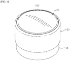
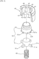
- the cap 20 which is constructed as a single assembly so as to open and close the container body 10, includes an inner airtight cap 30, an ascending/descending guide cap 40, a knock member 50 disposed in the ascending/descending guide cap and elastically supported by an elastic member 60, a push cap 70 fixedly coupled to the knock member, an opening/closing operation unit 80, and an outer cap 90 coupled to the outer portion of the push cap in order to support the same, and all of these components are united into a single structure that is removed from and coupled to the container body 10 as a single unit.
- the inner airtight cap 30 functions to maintain the upper end of the opening 12 in the container body 10 in an airtight state when the cap 20 is operated to close the container body 10, and includes a short airtight pipe 31, which extends downwards from the bottom surface of the inner airtight cap so as to be closely fitted in the inner circumferential surface of the upper end of the opening 12 in the container body 10, and an airtight ring 32, which is formed of an elastic material and is integrally attached to a marginal portion of the bottom surface of the inner airtight cap so as to be in close contact with the top surface of the opening in the container body in an airtight manner.
- the inner airtight cap 30 includes a short support pipe 33, which integrally extends from a central portion of the top surface of the inner airtight cap so as to be open in the upward direction, and one or more support ribs 34, which are equidistantly arranged around the short support pipe and each of which has a hinge recess 34a therein.
- the ascending/descending guide cap 40 is fixedly coupled to the short support pipe 33 of the inner airtight cap 30.
- the ascending/descending guide cap has a hollow shape, which is open in a certain direction in order to guide unidirectional rotation and vertical movement of the knock member 50, which will be described later.
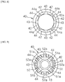
- the ascending/descending guide cap has a through-hole 41, which is formed at the central portion of the top surface of the ascending/descending guide cap so as to be open in the upward direction, a plurality of rotation guide blocks 42, which are equidistantly arranged along the inner circumferential surface of the through-hole and each of which is provided at the lower end thereof with an inclined guide surface 42a that is formed to be inclined in a certain direction, first guide recesses 43 and second guide recesses 44, each of which is defined between the rotation guide blocks and which are alternately arranged, as shown in FIG. 8 , and latching steps 44a, each of which is formed at the lower portion of each of the second guide recesses.
- the knock member 50 is disposed inside the ascending/descending guide cap 40 so as to be elastically supported by the elastic member 60.
- the knock member 50 includes a cam member 51, which is elastically supported by the elastic member 60 from below, and a rotation support member 52, to which the cam member is coupled so as to rotate relative to the rotation support member.
- the cam member is provided with a plurality of first guide protrusions 51a on the outer circumferential surface of the lower end thereof, and the rotation support member is provided with a plurality of second guide protrusions 52a on the outer circumferential surface of the lower end thereof.
- Each of the first guide protrusions 51a formed at the cam member 51 is provided at the top surface thereof with a rotation guide surface 51b, which is inclined in a certain direction, and the rotation support member 52 is provided on the bottom surface thereof with a series of saw-teeth 52b, each of which is inclined at the same angle as the rotation guide surface 51b so as to mesh with the rotation guide surface.
- the ascending/descending guide cap 40 and the knock member 50 function to limit the vertical movement of the push cap 70, which will be described later, to an appropriate extent when the cap 20 is locked to and unlocked from the container body 10.
- the first guide protrusions 51a formed at the cam member 51 and the second guide protrusions 52a formed at the rotation support member 52 may be formed to have different protruding lengths from each other.
- the first guide protrusions 51a formed at the cam member 51 have a length that allows the first guide protrusions 51a to move vertically only along the first guide recesses 43 in the ascending/descending guide cap 40
- the second guide protrusions 52a formed at the rotation support member 52 have a length that prevents the second guide protrusions 52a from being caught by the latching steps 44a of the second guide recesses 44 and allows the second guide protrusions 52a to move vertically along the first guide recesses 43 and the second guide recesses 44.
- the first guide protrusions 51a formed at the cam member 51 move vertically together with the second guide protrusions 52a of the rotation support member 52 only along the first guide recesses 43, and, when the first guide protrusions 51a of the cam member 51 are located in the second guide recesses 44, as shown in FIG. 9 , the first guide protrusions 51a are caught by the lower ends 44a of the second guide recesses 44 and are thus prevented from moving vertically, and only the second guide protrusions 52a formed at the rotation support member 52 move vertically along the second guide recesses 44.
- the elastic member 60 which elastically supports the knock member 50, applies elastic force to the knock member so that the knock member is constantly biased upwards and is preferably embodied as a compressive coil spring; however, the elastic member may be formed in various other configurations and of various materials as long as the function of elastically supporting the knock member is achieved.
- the push cap 70 covers the upper portion of the inner airtight cap 30.
- the push cap is formed to be open in a certain direction, and includes a push portion 71, which has a curved surface that ascends to an apex and which is provided on the bottom surface thereof with a short coupling pipe 73 that extends downwards, and a lateral portion 72, which extends downwards from the periphery of the push portion. Therefore, the push cap 70 is coupled to the knock member 50 in a manner such that the short coupling pipe 73 is integrally coupled to the rotation support member 52 of the knock member, with the result that the push cap and the knock member are pressed together.
- the push cap 70 is provided with latching ribs 74, which are equidistantly arranged on the inner circumferential surface of the lateral portion 72.
- the latching ribs 74 may preferably be provided in a plural number, spaced a predetermined distance apart from each other; however, the latching ribs may alternatively be formed in a unitary configuration.
- the push cap 70 has a concave recess 71a formed in the top surface of the push portion 71, to which a name plate 75 for showing a company logo, a product name, an advertising phrase, etc. is attached.
- the opening/closing operation unit 80 may be provided in a plural number so as to be separate from one another.
- the opening/closing operation unit includes a hinge pin 82, which is provided at one end portion of a connection portion 81 so as to be fitted into the hinge recess 34a formed in each of the support ribs 34 of the inner airtight cap 30, and an opening/closing wing 83, which is bent from the opposite end of the connection portion.
- the opening/closing wing includes a first latching step 83a, which is formed on the upper portion of the outer circumferential surface of the opening/closing wing so as to be forcibly caught by or released from the latching ribs 74 formed on the inner circumferential surface of the lateral portion 72 of the push cap 70, and a second latching step 83b, which is formed on the inner circumferential surface of the lower end of the opening/closing wing so as to be forcibly caught by or released from the latching rim 14 of the container body 10.
- the opening/closing operation unit 80 further includes coupling protrusions 84, which are formed on the inner circumferential surface of the opening/closing wing 83 of the opening/closing operation unit 80 so as to mate with the coupling protrusions 16 formed on the outer circumferential surface of the upper end of the opening 12 in the container body 10.
- the cap and the container body 10 may be assembled such that unintentional rotating manipulation cannot be performed.
- the outer cap 90 is coupled to the outer portion of the push cap 70 so that the vertical movement of the push cap can be achieved.
- the outer cap also functions as a portion that is grabbed with the hand when the cap 20 is finally removed from the container body. It is preferable for the outer cap, which is assembled with the push cap, to be formed such that the lower end portion thereof extends to such an extent that it covers a portion near the lower end of the container body 10, as shown in FIG. 4 .
- the outer cap which covers the outer periphery of the push cap, to be formed to support the push cap so that the vertical movement of the push cap can be achieved.
- the outer cap 90 may further include a cover ring 91, which is fixedly coupled to the inner periphery of the lower end portion of the outer cap.
- the cover ring 91 functions to prevent the outer cap 90, to which the push cap 70 is coupled so as to move vertically, from moving further downwards than necessary, and also functions as a cover for preventing the opening/closing operation unit 80, disposed inside the push cap, from being seen from outside.
- the cover ring 91 is removed from or coupled to the container body 10 together with the outer cap 90.
- the lower end of the inner container body 10b is inserted into the outer container body 10a such that the upper end of the inner container body is forcibly secured to the outer container body, whereby the container body 10 is formed as a unitary body and the inner container body is prevented from being separated from the outer container body unless the inner container body is intentionally removed from the outer container body.
- this process of assembling the inner container body with the outer container body is omitted.
- the process of assembling the cap 20 includes a step of fitting the ascending/descending guide cap 40, in which the knock member 50 is elastically supported by the elastic member 60, into the short support pipe 33 formed on the top surface of the inner airtight cap 30.
- the opening/closing operation units 80 are coupled to the respective support ribs 34 of the inner airtight cap 30.
- the short coupling pipe 73 of the push cap 70 is fixedly coupled to the rotation support member 52 of the knock member 50, which is exposed outside through the through-hole 41 in the ascending/descending guide cap 40.
- the outer cap 90 is coupled to the outer periphery of the push cap 70, and the cover ring 91 is integrally secured to the inner circumferential surface of the lower end of the outer cap.
- the cap 20 is assembled into a unitary construction, which is removed from or coupled to the container body 10 as a single unit.
- FIG. 4 shows the state in which the cap 20 is locked to the container body 10, in which the push cap 70 is maintained in the state of being pressed downwards with respect to the outer cap 90.
- the knock member 50 is also maintained in the state of being pressed and moved downwards, and the elastic member 60, which supports the knock member, is maintained in the state of being forcibly compressed.
- the first guide protrusions 51a of the cam member 51 of the knock member 50 are maintained in the state of being caught by the latching steps 44a formed at the lower ends of the second guide recesses 44 in the ascending/descending guide cap 40, and accordingly the push cap 70, which is maintained in the downwardly pressed state, does not unintentionally ascend.
- the hinge pin 82 of the opening/closing operation unit 80 is fitted into the hinge recess 34a formed in each of the support ribs 34a of the inner airtight cap 30 so as not to be separated therefrom, the outer periphery of the lower end of the opening/closing wing 83 is forcibly pressed by the latching ribs 74 formed on the inner circumferential surface of the lateral portion 72 of the push cap 70, and the second latching step 83b, formed on the inner circumferential surface of the lower end of the opening/closing wing, is forcibly caught by the latching rim 14 formed on the outer circumferential surface of the opening 12 in the container body 10.
- the cap 20 is stably maintained in the state of closing the container body 10.
- the opening/closing wing 83 of the opening/closing operation unit 80 is forcibly pressed toward the latching rim 14 of the container body by the latching ribs 74, and the coupling protrusions 84 formed on the inner circumferential surface of the opening/closing wing mate with the coupling protrusions 16 formed on the outer circumferential surface of the opening in the container body, whereby the container body 10 or the cap 20 is prevented from being rotated even if rotating force in either direction is applied thereto.
- the accommodation space 11 in the container body 10, in which contents are contained is sealed in an airtight manner, thereby preventing the contents from leaking while the cosmetic container is carried or stored.
- the opening/closing wing 83 of the opening/closing operation unit 80 is constantly maintained in the state of being pressed by the latching ribs 74 formed on the inner circumferential surface of the lateral portion 72 of the push cap, whereby it is impossible to separate the cap 20 from the container body 10.
- the ascending prevention state of the push cap 70 is released by the knock member 50, and, as shown in FIG. 4 , the second guide protrusions 52a formed at the rotation support member 52 of the knock member 50 also ascend to the uppermost latching position of the first guide recesses 43 in the ascending/descending guide cap 40.
- the latching ribs 74 formed at the push cap 70 also ascend and are forcibly brought into surface contact with the first latching step 83a formed on the outer circumferential surface of the opening/closing wing 83 of the opening/closing operation unit 80.
- the lower end portion of the opening/closing wing 83 is spread outwards about the hinge pin 82 fitted into the hinge recess 34a in the support rib 34, and, at the same time, the second latching step 83b formed on the inner circumferential surface of the opening/closing wing is forcibly separated from the latching rim 14 formed on the outer circumferential surface of the opening 12 in the container body 10, whereby the locking force of the cap is eliminated.
- the locking force of the cap 20 to the container body 10 is eliminated in a manner such that the opening/closing wing 83 of the opening/closing operation unit 80 is spread outwards in response to the ascent of the push cap 70.
- the outer cap 90 is grabbed and lifted up, as shown in FIG. 11 , it is possible to remove the cap 20 from the container body 10 and to open the accommodation space 11 in the container body, thereby allowing the contents in the accommodation space to be used.
- the opening/closing wing 83 of the opening/closing operation unit 80 is maintained in the state in which the lower end thereof is spread outwards and opened.
- the cap 20 when the cap 20 is intended to be coupled again to the container body 10 after the use of the contents is finished, as shown in FIG. 5 , the cap 20 is placed directly above the opening 12 in the container body 10 from the state shown in FIG. 11 , the push portion 71 of the push cap 70 is pressed again so that the push cap 70 and the knock member 50 descend while compressing the elastic member 60, and, at the same time, the first guide protrusions 51a of the cam member 51, which descend along the first guide recesses 43 in the ascending/descending guide cap 40, mesh with the saw-teeth 52b of the rotation support member 52 and are rotated to the position of the second guide recesses 44 in the ascending/descending guide cap 40 along the inclined guide surfaces 42a of the rotation guide blocks 42 and are finally caught by the latching steps 44a.
- the lower end portion of the opening/closing wing 83 of the opening/closing operation unit 80 is forcibly pressed inwards by the latching ribs 74 formed on the inner circumferential surface of the lateral portion 72 of the push cap 70, and the second latching step 83b is forcibly coupled to the latching rim 14 of the container body 10.
- the cap 20 can be conveniently removed from or coupled to the container body 10 merely by touching the push cap 70, the vertical movement of which is controlled by the ascending/descending guide cap 40 and the knock member 50 elastically supported by the elastic member 60 inside the ascending/descending guide cap, so that one or more opening/closing operation units 80, each having a portion hingedly coupled to the support ribs 34, perform the opening/closing operation so as to be caught by or released from the latching rim 14 of the container body 10.
Landscapes
- Engineering & Computer Science (AREA)
- Mechanical Engineering (AREA)
- Closures For Containers (AREA)
Applications Claiming Priority (2)
| Application Number | Priority Date | Filing Date | Title |
|---|---|---|---|
| KR1020160149915A KR101707455B1 (ko) | 2016-11-11 | 2016-11-11 | 원 터치 방식으로 캡이 개폐 조작되는 화장품 용기 |
| PCT/KR2016/013856 WO2018088617A1 (ko) | 2016-11-11 | 2016-11-29 | 원 터치 방식으로 캡이 개폐 조작되는 화장품 용기 |
Publications (2)
| Publication Number | Publication Date |
|---|---|
| EP3539409A1 true EP3539409A1 (de) | 2019-09-18 |
| EP3539409A4 EP3539409A4 (de) | 2020-06-03 |
Family
ID=58265475
Family Applications (1)
| Application Number | Title | Priority Date | Filing Date |
|---|---|---|---|
| EP16856472.2A Withdrawn EP3539409A4 (de) | 2016-11-11 | 2016-11-29 | Kosmetikbehälter mit kappe, die durch ein one-touch-verfahren geöffnet und geschlossen wird |
Country Status (7)
| Country | Link |
|---|---|
| US (1) | US20180132592A1 (de) |
| EP (1) | EP3539409A4 (de) |
| JP (1) | JP6613510B2 (de) |
| KR (1) | KR101707455B1 (de) |
| CN (1) | CN108307618A (de) |
| BR (1) | BR112017011423A2 (de) |
| WO (1) | WO2018088617A1 (de) |
Families Citing this family (43)
| Publication number | Priority date | Publication date | Assignee | Title |
|---|---|---|---|---|
| KR200480194Y1 (ko) * | 2013-12-12 | 2016-04-22 | 강성일 | 배출펌프를 구비한 파운데이션 용기 |
| FR3026725B1 (fr) * | 2014-10-03 | 2016-10-28 | Chanel Parfums Beaute | Pot de cosmetique comportant un couvercle a element d'accrochage basculant |
| FR3052036B1 (fr) * | 2016-06-03 | 2018-06-08 | Chanel Parfums Beaute | Pot a couvercle a element d'accrochage guide |
| USD845129S1 (en) * | 2016-11-01 | 2019-04-09 | Lg Household & Health Care Ltd. | Cosmetic vessel |
| KR101986281B1 (ko) * | 2017-03-20 | 2019-09-30 | 주식회사 씨티케이코스메틱스 | 원터치 화장품 케이스 |
| FR3067228B1 (fr) * | 2017-06-07 | 2019-07-05 | Chanel Parfums Beaute | Pot pour produit cosmetique |
| KR102015834B1 (ko) * | 2018-04-03 | 2019-08-29 | (주)더페이스샵 | 화장품 용기용 원터치 캡 |
| USD894738S1 (en) * | 2018-04-30 | 2020-09-01 | The Procter & Gamble Company | Cap for bottle for beauty care products |
| CN108577140A (zh) * | 2018-05-24 | 2018-09-28 | 洽兴包装工业(中国)有限公司 | 弹跳镜面口红 |
| KR102007825B1 (ko) * | 2018-08-08 | 2019-08-06 | (주)장업시스템 | 원터치 방식의 개폐 구조를 갖는 화장품 용기 |
| KR20200093961A (ko) * | 2019-01-29 | 2020-08-06 | 주식회사 씨티케이코스메틱스 | 화장품 용기 |
| USD921988S1 (en) * | 2019-02-08 | 2021-06-08 | Rea.Deeming Beauty, Inc. | Container for cosmetic sponge applicator |
| KR102153714B1 (ko) * | 2019-05-02 | 2020-09-09 | 주식회사 하이맥 | 승강 탈착형 용기커버를 구비한 용기 |
| CN110104318B (zh) * | 2019-05-06 | 2023-06-16 | 王崇恩 | 一种液体容器 |
| KR102241338B1 (ko) * | 2019-08-01 | 2021-04-16 | 주식회사 하이맥 | 승강 탈착형 용기커버를 구비한 용기 |
| USD926577S1 (en) * | 2019-09-23 | 2021-08-03 | Verdant Ventures | Tamper-resistant lid assembly |
| KR102282237B1 (ko) * | 2019-10-29 | 2021-07-27 | (주)연우 | 출몰식 용기 |
| USD927304S1 (en) * | 2019-11-14 | 2021-08-10 | Donny Lingle | Container closure |
| CN110979998A (zh) * | 2019-12-03 | 2020-04-10 | 天津长城万达罐头有限公司 | 一种具有防护功能的罐头 |
| KR102260884B1 (ko) * | 2019-12-09 | 2021-06-07 | 주식회사 하이맥 | 승강 탈착형 용기커버를 구비한 용기 |
| KR102283157B1 (ko) * | 2020-04-10 | 2021-07-28 | 정규철 | 캡의 개폐 조작이 용이한 화장품 용기 |
| JP7536283B2 (ja) | 2020-08-24 | 2024-08-20 | 吉田プラ工業株式会社 | キャップ付き容器 |
| USD968226S1 (en) * | 2020-10-06 | 2022-11-01 | PW Branding, Inc. | Cosmetic package |
| USD968224S1 (en) * | 2020-10-06 | 2022-11-01 | PW Branding, Inc. | Cosmetic package |
| USD968225S1 (en) * | 2020-10-06 | 2022-11-01 | PW Branding, Inc. | Cosmetic package |
| EP4464476A3 (de) * | 2020-11-05 | 2025-01-22 | Braun GmbH | Kopf einer körperpflegevorrichtung und körperpflegevorrichtung |
| FR3117463B1 (fr) * | 2020-12-10 | 2023-04-21 | Oreal | Dispositif de conditionnement d’un produit, notamment cosmétique, comprenant un capot verrouillé et déverrouillé par appui axial. |
| WO2022122791A1 (en) * | 2020-12-10 | 2022-06-16 | L'oreal | Device for packaging a product, notably a cosmetic product, comprising a cap locked and unlocked by axial pressure |
| KR102550546B1 (ko) | 2021-08-17 | 2023-07-03 | 씨앤알코스메틱스 주식회사 | 원터치 개폐 구조를 갖는 화장품 용기 |
| KR102319268B1 (ko) | 2021-09-08 | 2021-10-29 | 한국콜마주식회사 | 원터치 커넥터부를 포함하는 화장품 용기 |
| USD1004416S1 (en) * | 2021-10-27 | 2023-11-14 | Lg Household & Health Care Ltd. | Packaging container |
| USD1031458S1 (en) * | 2022-05-26 | 2024-06-18 | Human Race Pw, Llc | Cosmetic package assembly |
| USD1079479S1 (en) * | 2022-05-26 | 2025-06-17 | Human Race Pw, Llc | Cosmetic package |
| USD1078484S1 (en) * | 2022-05-26 | 2025-06-10 | Human Race Pw, Llc | Cosmetic package |
| USD1078476S1 (en) * | 2022-05-26 | 2025-06-10 | Human Race Pw, Llc | Cosmetic package |
| KR102498612B1 (ko) * | 2022-07-06 | 2023-02-10 | 주식회사 씨티케이 | 용기의 캡 개폐장치 |
| USD1054298S1 (en) * | 2022-07-13 | 2024-12-17 | Albea Services | Container for cosmetic products |
| KR102465121B1 (ko) * | 2022-08-22 | 2022-11-10 | 주식회사 씨티케이 | 에코 화장품용기 |
| CN115399562A (zh) * | 2022-09-08 | 2022-11-29 | 宁波正匠塑业科技有限公司 | 单手按压开盖式化妆品容器 |
| CN118850540A (zh) * | 2023-04-27 | 2024-10-29 | 林在重 | 配备刮痧功能的容器盖 |
| KR102922009B1 (ko) | 2024-01-05 | 2026-02-03 | (주)미금테크 | 개폐되는 노즐이 형성된 밀폐용기 뚜껑 구조 |
| JP1777929S (ja) * | 2024-02-21 | 2024-08-16 | 液体石鹸ディスペンサー用容器 | |
| JP1777930S (ja) * | 2024-02-21 | 2024-08-16 | 液体石鹸ディスペンサー用容器 |
Family Cites Families (12)
| Publication number | Priority date | Publication date | Assignee | Title |
|---|---|---|---|---|
| US7223360B2 (en) * | 2002-10-31 | 2007-05-29 | Rii Acquisition Corp. | Method of molding decorative elements for consumer packaging |
| KR200420228Y1 (ko) * | 2006-04-04 | 2006-07-03 | 주식회사 태평양 | 용기 안전 캡 |
| KR200442230Y1 (ko) * | 2006-12-11 | 2008-10-20 | (주)아모레퍼시픽 | 펌프용기의 누름버튼 잠금장치 |
| KR200437214Y1 (ko) | 2007-01-09 | 2007-11-13 | (주)아모레퍼시픽 | 원터치 개폐가 가능한 용기의 안전 캡 |
| JP5179800B2 (ja) * | 2007-08-21 | 2013-04-10 | 紀伊産業株式会社 | 化粧料容器 |
| US20090120938A1 (en) * | 2007-11-14 | 2009-05-14 | En-Hsin Liu | Cosmetic container |
| KR200451865Y1 (ko) * | 2008-10-15 | 2011-01-17 | (주)아모레퍼시픽 | 내용물 배출펌프의 록킹구조를 갖는 화장품 용기 |
| US20110108054A1 (en) * | 2009-11-10 | 2011-05-12 | Lee Jong Chill | Knock-type cosmetic vessel |
| KR200472284Y1 (ko) * | 2013-04-11 | 2014-04-16 | (주)아모레퍼시픽 | 수직 버튼식 개폐장치를 갖는 화장용기 |
| KR101643456B1 (ko) * | 2014-02-14 | 2016-07-28 | 주식회사 엘지생활건강 | 화장품 용기 |
| KR20160015642A (ko) * | 2014-07-31 | 2016-02-15 | 박태영 | 다기능성 용기 |
| FR3056387B1 (fr) * | 2016-09-28 | 2018-11-23 | Parfums Christian Dior | Pot apte a contenir un produit solide, liquide ou pateux |
-
2016
- 2016-11-11 KR KR1020160149915A patent/KR101707455B1/ko not_active Expired - Fee Related
- 2016-11-29 EP EP16856472.2A patent/EP3539409A4/de not_active Withdrawn
- 2016-11-29 WO PCT/KR2016/013856 patent/WO2018088617A1/ko not_active Ceased
- 2016-11-29 JP JP2017518450A patent/JP6613510B2/ja not_active Expired - Fee Related
- 2016-11-29 CN CN201680003035.8A patent/CN108307618A/zh not_active Withdrawn
- 2016-11-29 BR BR112017011423-2A patent/BR112017011423A2/pt not_active Application Discontinuation
-
2017
- 2017-08-18 US US15/681,121 patent/US20180132592A1/en not_active Abandoned
Also Published As
| Publication number | Publication date |
|---|---|
| KR101707455B1 (ko) | 2017-02-17 |
| CN108307618A (zh) | 2018-07-20 |
| WO2018088617A1 (ko) | 2018-05-17 |
| JP6613510B2 (ja) | 2019-12-04 |
| BR112017011423A2 (pt) | 2018-09-11 |
| JP2019501675A (ja) | 2019-01-24 |
| US20180132592A1 (en) | 2018-05-17 |
| EP3539409A4 (de) | 2020-06-03 |
Similar Documents
| Publication | Publication Date | Title |
|---|---|---|
| US20180132592A1 (en) | Cosmetic container configured to be opened and closed by operation of cap in one-touch manner | |
| EP3214008B1 (de) | Trinkgefässe und zugehörige verfahren | |
| EP2298659B1 (de) | Verbindungsstruktur | |
| KR101348305B1 (ko) | 밀폐용기 및 밀폐용기용 커버 | |
| US5765705A (en) | Child resistant closure | |
| KR102089711B1 (ko) | 밀폐형 립스틱 용기 | |
| JP7037179B2 (ja) | 詰め替えセット及び容器 | |
| JP6576622B2 (ja) | 注出容器 | |
| KR101518258B1 (ko) | 열림 방지용 용기 마개 | |
| JP4263230B2 (ja) | キャップ付容器 | |
| KR20170138836A (ko) | 파우더 화장품 케이스 | |
| US11072468B2 (en) | Container with security lock | |
| JP7822889B2 (ja) | 蓋付き容器 | |
| US20140246433A1 (en) | Child-Resistant Container with Hinged Closure | |
| EP2263947B1 (de) | Behälter mit einem hermetischen, mit einer Sicherheitseinrichtung versehenen Verschluss | |
| KR102139301B1 (ko) | 조립식 pet 손잡이를 구비한 pet 용기 | |
| JP6716448B2 (ja) | 抽出容器 | |
| KR101804673B1 (ko) | 나사 및 힌지의 복합 개방 구조를 갖는 화장품 용기 | |
| JP2003104429A (ja) | 補助蓋付き安全キャップ | |
| JP6086722B2 (ja) | ヒンジキャップ | |
| JP5587729B2 (ja) | キャップ付き容器 | |
| KR20140041011A (ko) | 한 손으로 뚜껑을 개방할 수 있는 식품 보관용 용기 | |
| KR200396092Y1 (ko) | 안전마개 및 이와 결합되는 용기구조 | |
| JP7166726B2 (ja) | 粒状物用容器 | |
| JP2003040302A (ja) | 補助蓋付き安全キャップ |
Legal Events
| Date | Code | Title | Description |
|---|---|---|---|
| STAA | Information on the status of an ep patent application or granted ep patent |
Free format text: STATUS: UNKNOWN |
|
| STAA | Information on the status of an ep patent application or granted ep patent |
Free format text: STATUS: THE INTERNATIONAL PUBLICATION HAS BEEN MADE |
|
| PUAI | Public reference made under article 153(3) epc to a published international application that has entered the european phase |
Free format text: ORIGINAL CODE: 0009012 |
|
| STAA | Information on the status of an ep patent application or granted ep patent |
Free format text: STATUS: REQUEST FOR EXAMINATION WAS MADE |
|
| 17P | Request for examination filed |
Effective date: 20170428 |
|
| AK | Designated contracting states |
Kind code of ref document: A1 Designated state(s): AL AT BE BG CH CY CZ DE DK EE ES FI FR GB GR HR HU IE IS IT LI LT LU LV MC MK MT NL NO PL PT RO RS SE SI SK SM TR |
|
| AX | Request for extension of the european patent |
Extension state: BA ME |
|
| DAV | Request for validation of the european patent (deleted) | ||
| DAX | Request for extension of the european patent (deleted) | ||
| A4 | Supplementary search report drawn up and despatched |
Effective date: 20200506 |
|
| RIC1 | Information provided on ipc code assigned before grant |
Ipc: A45D 40/00 20060101ALI20200428BHEP Ipc: A45D 34/00 20060101AFI20200428BHEP Ipc: B65D 41/16 20060101ALI20200428BHEP |
|
| STAA | Information on the status of an ep patent application or granted ep patent |
Free format text: STATUS: THE APPLICATION IS DEEMED TO BE WITHDRAWN |
|
| 18D | Application deemed to be withdrawn |
Effective date: 20201208 |