EP3539436A1 - Tube d'extension pour aspirateur électrique - Google Patents
Tube d'extension pour aspirateur électrique Download PDFInfo
- Publication number
- EP3539436A1 EP3539436A1 EP17869541.7A EP17869541A EP3539436A1 EP 3539436 A1 EP3539436 A1 EP 3539436A1 EP 17869541 A EP17869541 A EP 17869541A EP 3539436 A1 EP3539436 A1 EP 3539436A1
- Authority
- EP
- European Patent Office
- Prior art keywords
- extension tube
- vacuum cleaner
- conductive
- tube
- illustrates
- Prior art date
- Legal status (The legal status is an assumption and is not a legal conclusion. Google has not performed a legal analysis and makes no representation as to the accuracy of the status listed.)
- Withdrawn
Links
- 238000006073 displacement reaction Methods 0.000 claims description 2
- 239000000428 dust Substances 0.000 description 73
- 229920000049 Carbon (fiber) Polymers 0.000 description 36
- 239000004917 carbon fiber Substances 0.000 description 36
- VNWKTOKETHGBQD-UHFFFAOYSA-N methane Chemical compound C VNWKTOKETHGBQD-UHFFFAOYSA-N 0.000 description 32
- 230000002093 peripheral effect Effects 0.000 description 30
- 239000010410 layer Substances 0.000 description 26
- 239000012634 fragment Substances 0.000 description 14
- 238000005192 partition Methods 0.000 description 12
- 230000002265 prevention Effects 0.000 description 10
- 229920005989 resin Polymers 0.000 description 8
- 239000011347 resin Substances 0.000 description 8
- 239000000853 adhesive Substances 0.000 description 7
- 230000001070 adhesive effect Effects 0.000 description 7
- 238000012856 packing Methods 0.000 description 7
- 238000001514 detection method Methods 0.000 description 6
- 238000010079 rubber tapping Methods 0.000 description 6
- 230000002457 bidirectional effect Effects 0.000 description 4
- 238000004140 cleaning Methods 0.000 description 4
- 229920001971 elastomer Polymers 0.000 description 4
- 238000003466 welding Methods 0.000 description 4
- 229920000122 acrylonitrile butadiene styrene Polymers 0.000 description 3
- 230000007423 decrease Effects 0.000 description 3
- WABPQHHGFIMREM-UHFFFAOYSA-N lead(0) Chemical compound [Pb] WABPQHHGFIMREM-UHFFFAOYSA-N 0.000 description 3
- OKTJSMMVPCPJKN-UHFFFAOYSA-N Carbon Chemical compound [C] OKTJSMMVPCPJKN-UHFFFAOYSA-N 0.000 description 2
- 238000013459 approach Methods 0.000 description 2
- 229910052799 carbon Inorganic materials 0.000 description 2
- 239000011247 coating layer Substances 0.000 description 2
- 238000009434 installation Methods 0.000 description 2
- 238000005304 joining Methods 0.000 description 2
- 238000010030 laminating Methods 0.000 description 2
- 239000002184 metal Substances 0.000 description 2
- 238000000034 method Methods 0.000 description 2
- 229920001875 Ebonite Polymers 0.000 description 1
- 230000004075 alteration Effects 0.000 description 1
- 230000008878 coupling Effects 0.000 description 1
- 238000010168 coupling process Methods 0.000 description 1
- 238000005859 coupling reaction Methods 0.000 description 1
- 239000013013 elastic material Substances 0.000 description 1
- 239000000806 elastomer Substances 0.000 description 1
- 230000006872 improvement Effects 0.000 description 1
- 238000009413 insulation Methods 0.000 description 1
- 239000000463 material Substances 0.000 description 1
- 230000007246 mechanism Effects 0.000 description 1
- 238000012986 modification Methods 0.000 description 1
- 230000004048 modification Effects 0.000 description 1
- 238000000465 moulding Methods 0.000 description 1
- 229920003023 plastic Polymers 0.000 description 1
- 239000004033 plastic Substances 0.000 description 1
- 238000003825 pressing Methods 0.000 description 1
- 230000009467 reduction Effects 0.000 description 1
- 230000001960 triggered effect Effects 0.000 description 1
- 239000013585 weight reducing agent Substances 0.000 description 1
Images










Classifications
-
- A—HUMAN NECESSITIES
- A47—FURNITURE; DOMESTIC ARTICLES OR APPLIANCES; COFFEE MILLS; SPICE MILLS; SUCTION CLEANERS IN GENERAL
- A47L—DOMESTIC WASHING OR CLEANING; SUCTION CLEANERS IN GENERAL
- A47L5/00—Structural features of suction cleaners
- A47L5/12—Structural features of suction cleaners with power-driven air-pumps or air-compressors, e.g. driven by motor vehicle engine vacuum
- A47L5/22—Structural features of suction cleaners with power-driven air-pumps or air-compressors, e.g. driven by motor vehicle engine vacuum with rotary fans
- A47L5/24—Hand-supported suction cleaners
- A47L5/26—Hand-supported suction cleaners with driven dust-loosening tools
-
- A—HUMAN NECESSITIES
- A47—FURNITURE; DOMESTIC ARTICLES OR APPLIANCES; COFFEE MILLS; SPICE MILLS; SUCTION CLEANERS IN GENERAL
- A47L—DOMESTIC WASHING OR CLEANING; SUCTION CLEANERS IN GENERAL
- A47L9/00—Details or accessories of suction cleaners, e.g. mechanical means for controlling the suction or for effecting pulsating action; Storing devices specially adapted to suction cleaners or parts thereof; Carrying-vehicles specially adapted for suction cleaners
- A47L9/24—Hoses or pipes; Hose or pipe couplings
- A47L9/242—Hose or pipe couplings
- A47L9/244—Hose or pipe couplings for telescopic or extensible hoses or pipes
-
- A—HUMAN NECESSITIES
- A47—FURNITURE; DOMESTIC ARTICLES OR APPLIANCES; COFFEE MILLS; SPICE MILLS; SUCTION CLEANERS IN GENERAL
- A47L—DOMESTIC WASHING OR CLEANING; SUCTION CLEANERS IN GENERAL
- A47L9/00—Details or accessories of suction cleaners, e.g. mechanical means for controlling the suction or for effecting pulsating action; Storing devices specially adapted to suction cleaners or parts thereof; Carrying-vehicles specially adapted for suction cleaners
- A47L9/24—Hoses or pipes; Hose or pipe couplings
- A47L9/242—Hose or pipe couplings
-
- A—HUMAN NECESSITIES
- A47—FURNITURE; DOMESTIC ARTICLES OR APPLIANCES; COFFEE MILLS; SPICE MILLS; SUCTION CLEANERS IN GENERAL
- A47L—DOMESTIC WASHING OR CLEANING; SUCTION CLEANERS IN GENERAL
- A47L9/00—Details or accessories of suction cleaners, e.g. mechanical means for controlling the suction or for effecting pulsating action; Storing devices specially adapted to suction cleaners or parts thereof; Carrying-vehicles specially adapted for suction cleaners
- A47L9/10—Filters; Dust separators; Dust removal; Automatic exchange of filters
- A47L9/12—Dry filters
- A47L9/122—Dry filters flat
-
- A—HUMAN NECESSITIES
- A47—FURNITURE; DOMESTIC ARTICLES OR APPLIANCES; COFFEE MILLS; SPICE MILLS; SUCTION CLEANERS IN GENERAL
- A47L—DOMESTIC WASHING OR CLEANING; SUCTION CLEANERS IN GENERAL
- A47L9/00—Details or accessories of suction cleaners, e.g. mechanical means for controlling the suction or for effecting pulsating action; Storing devices specially adapted to suction cleaners or parts thereof; Carrying-vehicles specially adapted for suction cleaners
- A47L9/10—Filters; Dust separators; Dust removal; Automatic exchange of filters
- A47L9/16—Arrangement or disposition of cyclones or other devices with centrifugal action
- A47L9/1658—Construction of outlets
- A47L9/1666—Construction of outlets with filtering means
-
- A—HUMAN NECESSITIES
- A47—FURNITURE; DOMESTIC ARTICLES OR APPLIANCES; COFFEE MILLS; SPICE MILLS; SUCTION CLEANERS IN GENERAL
- A47L—DOMESTIC WASHING OR CLEANING; SUCTION CLEANERS IN GENERAL
- A47L9/00—Details or accessories of suction cleaners, e.g. mechanical means for controlling the suction or for effecting pulsating action; Storing devices specially adapted to suction cleaners or parts thereof; Carrying-vehicles specially adapted for suction cleaners
- A47L9/24—Hoses or pipes; Hose or pipe couplings
-
- A—HUMAN NECESSITIES
- A47—FURNITURE; DOMESTIC ARTICLES OR APPLIANCES; COFFEE MILLS; SPICE MILLS; SUCTION CLEANERS IN GENERAL
- A47L—DOMESTIC WASHING OR CLEANING; SUCTION CLEANERS IN GENERAL
- A47L9/00—Details or accessories of suction cleaners, e.g. mechanical means for controlling the suction or for effecting pulsating action; Storing devices specially adapted to suction cleaners or parts thereof; Carrying-vehicles specially adapted for suction cleaners
- A47L9/24—Hoses or pipes; Hose or pipe couplings
- A47L9/242—Hose or pipe couplings
- A47L9/246—Hose or pipe couplings with electrical connectors
-
- A—HUMAN NECESSITIES
- A47—FURNITURE; DOMESTIC ARTICLES OR APPLIANCES; COFFEE MILLS; SPICE MILLS; SUCTION CLEANERS IN GENERAL
- A47L—DOMESTIC WASHING OR CLEANING; SUCTION CLEANERS IN GENERAL
- A47L9/00—Details or accessories of suction cleaners, e.g. mechanical means for controlling the suction or for effecting pulsating action; Storing devices specially adapted to suction cleaners or parts thereof; Carrying-vehicles specially adapted for suction cleaners
- A47L9/24—Hoses or pipes; Hose or pipe couplings
- A47L9/248—Parts, details or accessories of hoses or pipes
-
- A—HUMAN NECESSITIES
- A47—FURNITURE; DOMESTIC ARTICLES OR APPLIANCES; COFFEE MILLS; SPICE MILLS; SUCTION CLEANERS IN GENERAL
- A47L—DOMESTIC WASHING OR CLEANING; SUCTION CLEANERS IN GENERAL
- A47L9/00—Details or accessories of suction cleaners, e.g. mechanical means for controlling the suction or for effecting pulsating action; Storing devices specially adapted to suction cleaners or parts thereof; Carrying-vehicles specially adapted for suction cleaners
- A47L9/28—Installation of the electric equipment, e.g. adaptation or attachment to the suction cleaner; Controlling suction cleaners by electric means
- A47L9/2857—User input or output elements for control, e.g. buttons, switches or displays
-
- A—HUMAN NECESSITIES
- A47—FURNITURE; DOMESTIC ARTICLES OR APPLIANCES; COFFEE MILLS; SPICE MILLS; SUCTION CLEANERS IN GENERAL
- A47L—DOMESTIC WASHING OR CLEANING; SUCTION CLEANERS IN GENERAL
- A47L9/00—Details or accessories of suction cleaners, e.g. mechanical means for controlling the suction or for effecting pulsating action; Storing devices specially adapted to suction cleaners or parts thereof; Carrying-vehicles specially adapted for suction cleaners
- A47L9/32—Handles
- A47L9/322—Handles for hand-supported suction cleaners
Definitions
- the present invention relates to an extension tube for an electric vacuum cleaner.
- Patent Literature 1 suggests an extension tube comprising a tube body; a cover attached to an outer surface of the tube body and extending in a longitudinal direction; an insulating resin plate provided at a space between the tube body and the cover; and lead wires placed on and supported by the insulating resin plate, wherein both ends of each lead wire are exposed to the outside so as to be electrically connectable with terminals of a vacuum cleaner body and of an intake port body.
- the extension tube described in Patent Literature 1 becomes thick because of comprising the insulating resin plate; the lead wires; and the cover, each of which being placed on an outer surface of the tube body and extending along a longitudinal direction, resulting in an increase in a total weight of the extension tube in addition to impairing ease of gripping the extension tube; therefore, there arises a problem that operability of the extension tube decreases at a time when determining a direction of the intake port body with use of the extension tube.
- the present invention has an object of providing an extension tube for an electric vacuum cleaner having a reduced weight and being easier to be gripped in addition to being easier to be operated.
- the present invention provides an extension tube for an electric vacuum cleaner, the extension tube comprising a tube body and a conductive unit provided so as to be laid in the tube body, wherein the conductive unit includes conductive cables and a hollow plate that contains the conductive cables.
- the extension tube according to the present invention is applicable to, for example, an electric vacuum cleaner in which an intake port body having a motor-driven rotary brush incorporated therein is connected to a vacuum cleaner body and which supplies electric power to the motor from the vacuum cleaner body via the extension tube to clean a floor surface while rotating the rotary brush in the intake port body.
- the conductive unit is compactly provided inside the tube body, and the tube body is not so thick. Therefore, the extension tube has reduced weight and is easier to be gripped, which leads to improved operability when a user changes the direction of movement of the intake port body via the extension tube.
- Figure 1 illustrates a left-side view of an electric vacuum cleaner in accordance with Embodiment 1 of the present invention.
- An electric vacuum cleaner 1 in accordance with Embodiment 1 comprises a vacuum cleaner body 10, an extension tube 20, and an intake port body 40.
- the extension tube may or may not have a structure that can extend the tube itself.
- the vacuum cleaner of the present invention can be used as a stick vacuum cleaner having the extension tube installed between the intake port body and the vacuum cleaner body, and has a long distance from the electric vacuum cleaner body to the intake port body.
- Figure 2 illustrates a perspective view of the vacuum cleaner body of the electric vacuum cleaner in accordance with Embodiment 1; and Figure 3 illustrates a left-side cross-section view of an inner structure of an operating portion in a handle of the vacuum cleaner body of Fig. 2 .
- Figure 4 illustrates a left-side cross-section view of an inner structure of the vacuum cleaner body of Fig. 2 ; and
- Figure 5 illustrates a perspective view of a disassembled housing of a drive unit of the vacuum cleaner body of Fig. 2 .
- Figure 6(A) illustrates the electric vacuum cleaner in accordance with Embodiment 1 that is placed on a floor; and Figure 6(B) illustrates the electric vacuum cleaner in accordance with Embodiment 1 that lies on a floor.
- the vacuum cleaner body 10 comprises a drive unit 11, a dust cup unit 12 detachably attached to the drive unit 11, and a battery 13.
- the drive unit 11 has a body 11a containing an electric blower 11am; a battery mounting part 11b communicating with the body 11a; a handle 11c having two ends that communicate with the body 11a and the battery mounting part 11b, respectively; and an intake tube 11d that communicates with a joint part connecting the body 11a to the handle 11c and projects in an opposite direction from the handle 11c.
- the intake tube 11d side is regarded as the front side; the handle 11c side is regarded as the rear side; the battery mounting part 11b side is regarded as the bottom side; the opposite side from the battery mounting part 11b is regarded as the upper side; the left side in a state where the handle 11c is positioned frontward is regarded as a left direction; and the right side in this state of the handle is regarded as a right direction.
- the body 11a is configured to have a shell which is a cylindrical housing part having a front opening 11a 1 , and this front opening 11a 1 has lattice-shaped ribs.
- the body 11a has an inner flange along a fringe of the front opening 11a 1 , and a lower part of the inner flange is a wide-width inner flange wide portion 11a 11 .
- the inner flange wide portion 11a 11 is provided with the following component parts: a locking convex portion 11a 12 and an engaging concave portion 11a 13 detachably locking to a locking concave portion 12c 11 and an engaging nail 12b 23 , respectively, of a second locking mechanical section 12b 2 , which is provided to the dust cup unit 12 (which will be described below).
- the locking convex portion 11a 12 projects toward the bottom side, and the engaging concave portion 11a 13 opens toward the front side.
- the battery mounting part 11b opens toward the bottom side and the rear side, and has a concave portion having terminals in its back that are electrically connectable with terminals of the battery 13; and the battery mounting part is configured to enable the battery 13 to be inserted into its concave portion from its rear side and to be mounted therein and also is configured to enable the battery 13 to be drawn therefrom toward the rear side and to be removed (or detached) from the concave portion.
- the battery mounting part 11b is configured to have concave channels that extend in a front-rear direction and are placed on a right-left inner side surface of the concave portion.
- the battery 13 is configured to have convex portions on its right-left side surface so that the convex portions on the both sides can respectively slide and fit into the concave channels on the both sides at a time when the battery 13 is mounted into the battery mounting part 11b.
- the handle 11c has an upper curved portion 11c 1 and a lower curved portion 11c 2 , both of which roughly having the shape of the letter "U"; and the upper curved portion 11c 1 has an operating portion 11e on its external side.
- the operating portion 11e has the following component parts: a concave portion 11e 1 formed in a plastic housing that constitutes the upper curved portion 11c 1 of the handle 11c; a pad 11e 2 that is made of an elastic material (rubber, elastomer, etc.) and is mounted on the external side of the concave portion 11e 1 ; and a switch unit 11e 3 provided inside the concave portion 11e 1 (inside the housing).
- the operating portion 11e has a convex rib 11e 11 in a center of the concave portion 11e 1 ; and the convex rib 11e 11 has a pair of U-shaped slits formed at its front and rear positions; and an inner area of each U-shaped slit is an elastic and deformable blade spring 11e 12 .
- Each blade spring 11e 12 has a convex portion on its lower surface.
- the U-shaped slits of the concave portion 11e 1 have locking openings formed in front of and the back of the slits, respectively; and a pair of front and rear inserting locking fragments 11e 24 of the pad 11e 2 (which will be described below) are respectively inserted into the locking openings.
- the pad 11e 2 has, on its upper surface side, concave portions 11e 22 and 11e 23 in front of and the back of a center portion 11e 21 , respectively.
- the pad 11e 2 has, on its lower surface side, a convex portion at a corresponding position of the center portion 11e 21 and at a corresponding position of the pair of concave portions 11e 22 and 11e 23 ; and these convex portions have the inserting locking fragments 11e 24 formed at their front and rear positions, respectively.
- the center portion 11e 21 comes in contact with the convex rib 11e 11 ; and the concave portions 11e 22 and 11e 23 placed at the front and at the back come in contact with the blade springs 11e 12 , respectively.
- the switch unit 11e 3 in the handle 11c has a circuit board 11e 31 supported and fixed by a rib structure in the upper curved portion 11c 1 and also has a pair of front switch 11e 32 and rear switch 11e 33 provided on the circuit board 11e 31 .
- the circuit board 11e 31 is configured to enable the following operations. For example, power is turned on by pushing the front switch 11e 32 or the rear switch 11e 33 . After that, pushing the front switch 11e 32 once turns on a high mode; pushing the front switch twice turns on a standard mode; and pushing the front switch three times or more allows these modes to repeat. The power can be shut down by pushing the rear switch 11e 33 when the power is on.
- the intake tube 11d and the handle 11e are assembled (or built) with a first member 11x, a second member 11y, and a third member 11z (which will be described below).
- the first member 11x extends in a front-rear direction and has at its front end a concave portion containing a locking member 11x 1 , a hooking member 11x 2 , etc.; and the first member also has at its rear end a fitting opening 11x 3 into which the fitting convex portion 11ax of the body 11a is fitted.
- the locking member 11x 1 is swingably installed in the first member 11x so as to rotate on a horizontal axis; and in a state where the above-described component parts are assembled, the front end of the locking member 11x functions as a push button that projects downward from an opening formed on the first member 11x to the outside.
- a rear end of the locking member 11x functions as an engaging nail 11x 11 that detachably engages with an engaging concave portion 22a 31 (see Figs. 9(A) to 9(C) ) of a first connecting pipe unit 22 (to be described below) of the extension tube 20 at a time when the extension tube 20 is inserted into a front opening 11d 1 of the intake tube 11d.
- a coil spring is placed between the first member 11x and the second member 11y, and biases downward the front end of the locking member 11x (to the outside).
- the hooking member 11x 2 detachably locks into a locking concave portion 12a 21 (to be described below) of the dust cup unit 12 installed in the vacuum cleaner body 10, and projects downward from the opening formed on the first member 11x to the outside.
- the first member 11x has, on its left-side surface of its middle part in a front-rear direction, a connection port 11x 4 that is connected with an outflow port 11y 11 (to be described below) of the second member 11y; and the first member also has, on its lower surface side of its rear end, a concave portion, where contains a first locking mechanical section 12b 1 , and a concave portion 11x 12 , into which a positioning convex portion 12c 21 is fitted, (which will be described below) of the dust cup unit 12 installed in the vacuum cleaner body 10.
- the third member 11z is to cover the intermediate rib structure portion 11y 2 and the inner handle structure portion 11y 3 , and has the pad 11e 2 of the operating portion 11e in its intermediate portion.
- the battery mounting part 11b has at its rear part a junction 11b 1 joining with a rear end of the second member 11y and a rear end of the third member 11z.
- This junction 11b 1 comprises a fixed projecting portion 11b 11 and a holding member 11b 12 provided swingably on the fixed projecting portion 11b 11 .
- the holding member 11b 12 is operated at a time when the battery 13 is removed (or detached).
- first member 11x, the second member 11y, and the third member 11z are assembled is that firstly the fitting opening 11x 3 of the first member 11x is fitted to the fitting convex portion 11ax of the body 11a.
- the pair of lead wires (not illustrated) drawn from the body 11a is electrically connected with the pair of female terminals 11y 12 of the second member 11y, respectively; then the pair of female terminals 11y 12 is attached to a front end of the second member 11y; and then the second member 11y is placed on the first member 11x.
- This enables the outflow port 11y 11 of the second member 11y to be connected with the connection port 11x 4 of the first member 11x, and enables the rear end of the second member 11y to come in contact with the fixed projecting portion 11b 11 of the junction 11b 1 .
- the holding member 11b 12 of the junction 11b 1 is swung toward the second member 11y side, and then the third member 11z is placed on the second member 11y. This enables the rear end of the third member 11z to hold down the holding member 11b 12 .
- the third member 11z is connected with the second member 11y with use of a tapping screw N; with the result that the rear end of the second member 11y and the rear end of the third member 11z join with the junction 11b 1 ; and the handle 11c and the intake tube 11d are formed.
- a support member 11f for supporting the vacuum cleaner body 10 is provided at a front end of the battery mounting part 11b so that the electric vacuum cleaner 1 can be placed on a floor surface F at a time when cleaning is discontinued.
- An example of a material of the support member 11f is hard rubber.
- This support member 11f is formed in a curved shape, in which a lower end thereof slightly protrudes to the front side, as viewed from the side surface side; and as viewed from the front side, the lower end surface is formed in an arc shape.
- the extension tube 20 of the electric vacuum cleaner 1 Since a space is provided at a lower part of the extension tube 20 of the electric vacuum cleaner 1 in the state of Fig. 6 (A) , there is a possibility that the extension tube 20 may be damaged if a force is applied from directly above.
- the support member 11f can be placed so as to be hooked on a top plate of a table or a backrest of a chair so as to lean the electric vacuum cleaner 1, instead of placing the electric vacuum cleaner 1 on the floor surface F.
- Figure 7 illustrates an exploded view of the drive unit of the electric vacuum cleaner in accordance with Embodiment 1; and Figure 8(A) illustrates a left-side view of the drive unit, and Figure 8(B) illustrates a left-side view of the vacuum cleaner body.
- Figure 9(A) illustrates a cross-section view taken from line I-I of Fig. A(A), and Figure 9(B) illustrates a cross-section view taken from line I-I of Fig. A(B).
- the body 11a of the drive unit 11 includes a pair of left electric blower cover 11ac 1 and right electric blower cover 11ac 2 for housing the electric blower 11am.
- the front opening 11a 1 of the body 11a is integrally formed at a front end of the left electric blower cover 11ac 1 ; and a half portion 11ax 1 of the fitting convex portion 11ax is integrally formed on each of the left electric blower cover 11ac 1 and the right electric blower cover 11ac 2 .
- the locking convex portion 11a 12 is installed in the front opening 11a 1 .
- the body 11a has in its inside a pair of vibration-preventing rubber parts 11ac 3 that secures a rear end of the electric blower 11am to the pair of left electric blower cover 11ac 1 and right electric blower cover 11ac 2 and also has a packing 11ac 4 placed between a front end of the electric blower 11am and an inner surface of a periphery of the front opening 11a 1 .
- the battery mounting part 11b of the drive unit 11 includes a pair of left battery mounting part housing 11bc 1 and right battery mounting part housing 11bc 2 connected by screws (not illustrated) with a lower part of the body 11a.
- the right battery mounting part housing 11bc 2 has the exhaust opening 11bx formed on its side surface; and at a front end and a rear end of the left battery mounting part housing 11bc 1 and the right battery mounting part housing 11bc 2 each, a pair of half portions 11bc 3 , which becomes a core of the support member 11f, and a pair of half portions 11bc 4 of the fixed projecting portion 11b 11 are integrally formed.
- the holding member 11b 12 is swingably attached to the pair of half portions 11bc 4 ; and the support member 11f is attached so as to cover the pair of half portions 11bc 3 after assembly.
- the support member 11f may be made of rubber to cover these half portions. Also, these half portions may be pasted with an adhesive.
- a partition plate 11bc 5 is continuously connected from the front end to the rear end of each of the battery mounting part housings 11bc 1 and 11bc 2 ; and at a lower end of a side wall of the battery mounting part housings, a lower end side wall portion 11bc 6 forming a concave channel for supporting a convex portion 13b on the left and right side surfaces of the battery 13 is continuously provided so as to be slidable in the front-rear direction.
- circuit board 11bc 7 having a terminal part 11bc 8 that is electrically connectable with a terminal part 13a of the battery 13.
- the handle 11c and the intake tube 11d of the drive unit 11 include the first member 11x, the second member 11y, and the third member 11z.
- an LED board 11xs having a plurality of LED lights which are turned on when the electric vacuum cleaner 1 is operating and when suction power is strong.
- a packing 11xp is attached to an outflow port (not illustrated) joining with the outflow port 11y 11 of the second member 11y; and the locking member 11x 1 and the hooking member 11x 2 are attached to the front end side of the first member.
- a filter attachment forgetting prevention member 11x 5 is attached so as to be rotatable around a shaft Q extending in the front-rear direction (see Fig. 4 and Fig. 9(A) ).
- This filter attachment forgetting prevention member 11x 5 (which may be hereinafter referred to as "attachment forgetting prevention member 11x 5 ") has a function of preventing the dust cup unit 12 with no filter portion 12c from being mounted even if the dust cup unit is about to be attached to the body 11a of the drive unit 11. This will be described in detail below.
- Figure 10(A) illustrates a perspective view of a dust cup to be installed in the electric vacuum cleaner in accordance with Embodiment 1
- Figure 10(B) illustrates an exploded view of the dust cup.
- Figure 11(A) illustrates a front view of the dust cup to be installed in the electric vacuum cleaner in accordance with Embodiment 1
- Figure 11(B) illustrates a cross-section view taken from line I-I of Fig. 11(A)
- Figure 11(C) illustrates a cross-section view taken from line II-II of Fig. 11(A)
- Figure 12(A) illustrates a plan cross-section view of a lower part of a dust cup unit
- Figure 12(B) illustrates a side cross-section view of the dust cup unit.
- the dust cup unit 12 includes the following component parts: a cylindrical dust collecting container 12a having a bottom portion 12a 1 , an outer peripheral portion 12a 2 , and an opening 12a 3 ; a cup portion 12b fitted in the opening 12a 3 of the dust collecting container 12a; a filter portion 12c detachably housed in the cup portion 12b; and an inner tube 12d detachably attached to the cup portion 12b so as to be housed in the dust collecting container 12a.
- the dust collecting container 12a is provided with the locking concave portion 12a 21 on the bottom portion 12a 1 side of the outer peripheral portion 12a 2 , the locking concave portion lying on a center line P as viewed from the front; and a locking convex portion 12a 22 is provided on the opening 12a 3 side on the center line P in the outer peripheral portion 12a 2 .
- the dust collecting container 12a is provided with an inlet 12a 23 for taking in dust-containing air at a position deviated from the center line P in the outer peripheral portion 12a 2 as viewed from the front.
- the dust collecting container 12a is provided with a quadrangular pyramidal projection 12a 4 at a position deviated from a center position of the bottom portion 12a 1 towards the external side.
- This projection 12a 4 has a function of preventing dust accumulated in a lower space (a space between the dust collecting container 12a and a small diameter tube 12d 21 (to be described below) of the inner tube 12d) of the dust collecting container 12a from being swirled by a whirling air current.
- the cup portion 12b has the following component parts: a bottom portion having a center hole and a reverse tapered surface around the center hole; a cylindrical outer peripheral portion communicating with the bottom portion; the first locking mechanical section 12b 1 and the second locking mechanical section 12b 2 provided on the outer peripheral portion; a pair of arcuate grooves 12b 3 provided around the center hole on a lower surface of the bottom portion; a packing 12b 4 provided near the bottom of the outer peripheral portion; and a notch portion 12bs provided at an opening end on the opposite side to the bottom portion of the outer peripheral portion.
- the cup portion 12b has a detection convex portion 12b 6 provided at a lateral position of the notch portion 12bs on its outer peripheral surface. Functions of this detection convex portion 12b 6 will be described in detail below.
- the first locking mechanical section 12b 1 includes the following component parts: an inverted U-shaped rib provided on the outer peripheral surface of the cup portion 12b; a pivoting piece 12b 11 attached to the rib so as to swingably pivot about a horizontal axis; a locking nail 12b 12 provided at the lower end of the pivoting piece 12b 11 and detachably locking to the locking convex portion 12a 22 of the dust collecting container 12a; and a coil spring 12b 13 that biases in a direction in which the locking nail 12b 12 locks to the locking convex portion 12a 22 .
- the second locking mechanical section 12b 2 includes the following component parts: a convex rib provided on the outer peripheral surface of the cup portion 12b; a slide member 12b 21 attached to this rib in a vertically slidable manner; the engaging nail 12b 22 provided at an upper end of the slide member 12b 21 and detachably engaging with the engaging concave portion 11a 13 of the vacuum cleaner body 10; and a coil spring 12b 23 that biases in a direction in which the engaging nail 12b 22 engages with the engaging concave portion 11a 13 .
- the second locking mechanical section 12b 2 includes the locking concave portion 12c 11 provided in the filter portion 12c (to be described below) as a component part.
- the filter portion 12c includes a pleated filter body 12c 1 having an annular outer peripheral frame portion and also includes a packing portion 12c 2 covering an outer peripheral portion of the outer peripheral frame portion of the filter body 12ci.
- the locking concave portion 12c 11 that opens inward in a radial direction is provided on an inner peripheral surface of the outer peripheral frame portion of the filter body 12c 1 ; and the positioning convex portion 12c 21 is provided on the outer peripheral surface of the packing portion 12c 2 .
- the locking concave portion 12c 11 and the positioning convex portion 12c 21 are disposed substantially opposite to each other.
- the positioning convex portion 12c 21 of the filter portion 12c is dropped into the notch portion 12bs of the cup portion 12b and is positioned. Then, the locking concave portion 12c 11 of the filter portion 12c is disposed at a position of the second locking mechanical section 12b 2 of the cup portion 12b.
- the packing portion 12c 2 is supported in close contact with a step portion provided on the inner peripheral surface of the opening of the cup portion 12b.
- the inner tube 12d has a tubular filter portion 12d 1 detachably attached to the cup portion 12b and also has a tubular partition member 12d 2 detachably attached to the tubular filter portion 12di.
- the tubular filter portion 12d 1 has a tubular frame 12d 11 having a plurality of slits extending in an axial direction and also has a mesh member 12d 12 provided on an outer peripheral portion of the tubular frame 12d 11 .
- the tubular frame 12d 11 has a pair of locking pieces 12d 111 , which are provided at an upper end of the outer peripheral portion of the tubular frame and detachably lock into a pair of arcuate grooves 12b 3 of the cup portion 12b, respectively, and also has a pair of locking pieces 12d 112 , which are provided at a lower end of the outer peripheral portion of the tubular frame and detachably lock into a pair of arcuate grooves 12d 231 (to be described below), respectively, of the partition member 12d 2 .
- the partition member 12d 2 has the following component parts: the small diameter tube 12d 21 ; a large diameter tube 12d 22 ; and a flange portion 12d 23 for connecting an upper end of the small diameter tube 12d 21 with an inner circumferential surface of the large diameter tube 12d 22 .
- the flange portion 12d 23 has the pair of arcuate grooves 12d 231 provided on an upper surface of the flange portion and detachably locking to the pair of locking pieces 12d 112 , respectively, at a lower end of the tubular filter portion 12di.
- the large diameter tube 12d 22 has an outer flange 12d 221 at its lower end.
- This outer flange 12d 221 has an elliptical shape in a plan view so that a gap between the outer flange 12d 221 and the dust collecting container 12a does not become even because of being elliptical; and narrow gaps S 1 and wide gaps S 2 are formed. This can prevent the dust having been accumulated in a lower part of the dust collecting container 12a from being blown up by whirling airflow G and also can prevent a decrease in suction power caused by the dust that attaches to the tubular filter portion 12d 1 of the inner tube 12d.
- the bottom portion 12a 1 of the dust collecting container 12a has the projection 12a 4 for preventing the dust from swirling; however, there is a possibility that the suction power may decrease, because a distance from the flange portion 12d 23 of the partition member 12d 2 to the bottom portion 12a 1 of the dust collecting container 12a is short; and in the absence of the outer flange 12d 221 , the dust hitting the projection 12a 4 rises up (or is blown up) to the tubular filter portion 12d 1 above the partition member 12d 2 and attaches to the tubular filter portion.
- the outer flange 12d 221 is provided at a lower end of the partition member 12d 2 so that the dust is not likely to fly up to the upper side.
- the gaps are not even-that is, the narrow gaps S 1 are formed in places where the dust hits the projection 12a 4 and is likely to swirl up, and the wide gaps S 2 are formed in places where the dust is not likely to swirl up-and the outer flange 12d 221 is configured to be oval, allowing the large dust to fall.
- the outer flange 12d 221 is set to be 61 mm in major diameter D 1 , 57 mm in minor diameter D 2 , 6 mm in narrow gap S 1 , and 8 mm in wide gap S 2 ; however, lengths are not limited to the above-mentioned lengths.
- the positions of the narrow gaps S 1 with respect to the projection 12a 4 are the same; that is, the outer flange 12d 221 is formed in an elliptical shape so that either one of the narrow gaps S1 is always at the position where the dust is likely to swirl up.
- the small diameter tube 12d 21 of the partition member 12d 2 fits to a positioning tube 12a 24 provided on the inner bottom surface of the dust collecting container 12a; and the small diameter tube comes in contact with a packing 12a 25 provided around the positioning tube 12a 24 .
- a space is formed in the dust collecting container 12a to accumulate the dust mass in the bottom side of the large diameter tube 12d 22 of the partition member 12d 2 .
- the locking concave portion 12a 21 of the dust cup unit 12 is hooked over the hooking member 11x 2 of the vacuum cleaner body 10 in a state where the dust cup unit 12 tilts to the intake tube 11d. Then, by making the dust cup unit 12 be parallel to the intake tube 11d with the hooking member 11x 2 as a fulcrum, the locking convex portion 11a 12 of the vacuum cleaner body 10 locks into the locking concave portion 12c 11 of the dust cup unit 12; and the engaging nail 12b 22 of the second locking mechanical section 12b 2 of the dust cup unit 12 engages with the engaging concave portion 11a 13 of the drive unit 11, and the installation is completed.
- the positioning convex portion 12c 21 of the filter portion 12c comes in contact with the first contacting portion 11x 51 of the attachment forgetting prevention member 11x 5 and pushes the first contacting portion 11x 51 into the concave portion 11x 12 , with the result that the attachment forgetting prevention member 11x 5 rotates; and the second contacting portion 11x 52 also rotates and protrudes downward toward the outside.
- the first contacting portion 11x 51 is pushed deep into the concave portion 11x 12
- the second contacting portion 11x 52 is housed in the concave portion 11x 12 again while approaching (or getting close to) the attachment forgetting prevention member 11x 5 .
- the detection convex portion 12b 6 of the dust cup unit 12 also moves toward the concave portion 11x 12 ; and the detection convex portion 12b 6 is housed in the concave portion 11x 12 while avoiding the second contacting portion 11x 52 .
- the positioning convex portion 12c 21 of the filter portion 12c comes in contact with the first contacting portion 11x 51 of the attachment forgetting prevention member 11x 5 so that the first contacting portion 11x 51 cannot be pushed into the concave portion 11x 12 , as described above; and the notch portion 12b 5 (see Fig. 10(B) ) of the cup portion 12b approaches (or moves closer to) the first contacting portion 11x 51 .
- the detection convex portion 12b 6 of the cup portion 12b comes in contact with the second contacting portion 11x 52 of the attachment forgetting prevention member 11x 5 and attempts to push the second contacting portion 11x 52 into the concave portion 11x 12 .
- the electric vacuum cleaner of the present invention can notify the user of forgetting the installation of the filter portion and of urging the user to properly use the electric vacuum cleaner; and this can prevent problems such that the electric vacuum cleaner is operated without the filter portion, and the drive unit having sucked in the dust breaks down (or get broken).
- Figure 13(A) illustrates a front view of an extension tube of the electric vacuum cleaner in accordance with Embodiment 1;
- Figure 13(B) illustrates a side view of the extension tube;
- Figure 13(C) illustrates a cross-section view taken from line I-I of Fig. 13(A) .
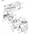
- Figure 14 illustrates an exploded view of the extension tube of Fig. 13(A) ;
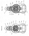
- Figure 15 illustrates an explanatory view of an inner structure of a first connecting pipe unit and a second connecting pipe unit of the extension tube of Fig. 13(A) which are viewed from the front side;
- Figure 16 illustrates a transverse cross-section view of the tube body of the extension tube of Fig. 13(A) ;
- Figure 17 illustrates an explanatory view of a layered structure of the tube body of the extension tube of Fig. 13(A) .
- the extension tube 20 includes the following component parts: a circular tube body 21; a tubular first connecting pipe unit 22 disposed at one end of the tube body 21 and detachably connected with the vacuum cleaner body; a tubular second connecting pipe unit 23 disposed at the other end of the tube body 21 and detachably connected with a suction port body; and a conductive unit 24 laid in the first connecting pipe unit 22, the tube body 21, and the second connecting pipe unit 23 therethrough.
- the tube body 21 is formed by laminating a plurality of tubular carbon fiber layers 21a and has a pipe shape (body pipe 21).
- the laminated tubular carbon fiber layers 21a are formed by layering a first tubular carbon fiber layer 21a 1 , a second tubular carbon fiber layer 21a 2 , and a third tubular carbon fiber layer 21a 3 in this order from the inside.
- the third tubular carbon fiber layer 21a 3 has a resin coating layer 21b as an outermost layer laminated on its outer peripheral surface.
- the tube body is processed as dry carbon.
- the dry carbon is to be molded in a pressurizable kiln using a pressure-resistant device capable of setting an inside pressure to be high.
- the first tubular carbon fiber layer 21a 1 is made of a unidirectional carbon fiber sheet having a plurality of carbon fibers extending parallel to a pipe longitudinal direction.
- the second tubular carbon fiber layer 21a 2 and the third tubular carbon fiber layer 21a 3 each are made of a bidirectional carbon fiber sheet having a plurality of warps and a plurality of wefts of carbon fibers.
- Used as the unidirectional carbon fiber sheet and the bidirectional carbon fiber sheet may be commercially-available prepreg sheets in which the carbon fibers are impregnated with a resin in advance.
- the carbon fibers can be made of diagonally crossed threads. Combinations of the crossed threads with the warps and the wefts, etc. may be freely arranged.
- the tube body 21 can be prepared by molding and laminating the first tubular carbon fiber layer 21a 1 , the second tubular carbon fiber layer 21a 2 , and the third tubular carbon fiber layer 21a 3 one by one using a mold by a known method. For example, a method for wrapping layers around a shaft rod, such as a metal rod, may be used.
- small notches 21n for positioning connection positions of the first connecting pipe unit 22 and the second connecting pipe unit 23 are formed by notching the already-formed tube body 21 at opposed positions of its both ends.
- a thickness T 1 of the first tubular carbon fiber layer 21a 1 is about 0.1 mm; a thickness T 2 of the second tubular carbon fiber layer and a thickness T 3 of the first tubular carbon fiber layer 21a 1 each is about 0.3 mm; a thickness T 4 of the resin coating layer 21b is about 0.1 mm; and an overall thickness T 5 is about 0.8 mm.
- the thickness of the first to third tubular carbon fiber layers 21a 1 to 21a 3 is based on a thickness of the unidirectional carbon fiber sheet and a thickness of the bidirectional carbon fiber sheet used for forming the layers.
- Each tubular carbon fiber layer 21a has both ends extending in the longitudinal direction of the tube; and end surfaces of these both ends have end surface contacting portions 21ax coming in contact with each other.
- the end surface contacting portions 21ax are formed by fusion-bonding the end surfaces of the both ends of the unidirectional carbon fiber sheet and of the bidirectional carbon fiber sheet used for forming each tubular carbon fiber layer 21a.
- one of the end surface contacting portions 21ax of the tubular carbon fiber layers 21a is configured not to overlap with the end surface contacting portion 21ax of the adjacent tubular carbon fiber layer 21a.
- each end surface contacting portion 21ax is disposed at a position shifted from a center angle by 120°. In this way, the positions of the end surface contacting portions 21ax can be shifted uniformly in the circumferential direction; and thus the tube body does not have any strong or weak parts, enabling the tube body to be uniformized (or making the tube body uniform).
- each tubular carbon fiber layer 21a has the end surface contacting portion 21ax, each tubular carbon fiber layer 21a is formed having a uniform thickness without any bumps (or bulges). That is, in a case of simply wrapping one carbon fiber sheet threefold around a metal rod at the time of preparing the tube body, bumps are formed between an end of the first (or undermost) wrapping and a beginning of the second (or middle) wrapping and between an end of the second (or middle) wrapping and a beginning of the third (or outermost) wrapping; however, such bumps are not formed in the tube body 21 of Embodiment 1 because the first to third tubular carbon fiber layers 21a 1 to 21a 3 are independent from each other. This enables the overall tube body 21 to have the uniform thickness and to be evenly rigid.
- the first connecting pipe unit 22 is to be connected with the vacuum cleaner body 10 and has a connecting pipe body 22a, a fragment 22b, and a (first) cover 22c.
- the connecting pipe body 22a has the following component parts: a (first) fixed portion 22a 1 inserted into one end of the tube body 21 and fixed thereto with an adhesive; a (first) terminal holder 22a 2 communicating with the fixed portion 22a 1 and holding a pair of male terminals 24a 2 (to be described below) of the conductive unit 24; and an inserting portion 22a 3 communicating with the terminal holder 22a 2 and inserted into the front opening 11d 1 of the vacuum cleaner body 10.
- the fixed portion 22a 1 has at its inner peripheral surface a pair of receiving pieces 22a 11 for receiving one end of a support plate 24b (to be described below) of the conductive unit 24; and the fixed portion has a positioning convex portion 22a 12 engaging with one of the notches 21n of the tube body 21 at a boundary portion between the fixed portion and the terminal holder 22a 2 on its outer peripheral surface.
- the terminal holder 22a 2 has a concave portion on the positioning convex portion 22a 12 side on its outer circumferential surface; and in this concave portion, a (first) drawing port 22a 21 is formed for drawing the pair of male terminals 24a 2 and lead wires 24a 1 of the conductive unit 24 from the inside to the outside.
- the concave portion of the terminal holder 22a 2 is provided with a rib structure 22a 22 for holding the pair of male terminals 24a 2 parallel to each other at predetermined intervals and also with a boss part 22a 23 into which a tapping screw 22d for attaching the cover 22c is screwed.
- the inserting portion 22a 3 has, on the positioning convex portion 22a 12 side on an outer peripheral surface of the inserting portion, the engaging concave portion 22a 31 detachably engaging with the engaging nail 11x 11 of the locking member 11x 1 of the vacuum cleaner body 10.
- the fragment 22b is to cover the drawing port 22a 21 of the connecting pipe body 22a through which the pair of lead wires 24a 1 is laid; and when using the electric vacuum cleaner 1, the fragment functions to prevent dust in the air passing through the extension tube 20 from flowing from the drawing port 22a 21 to the male terminal 24a 2 side, and protects the male terminals 24a 2 .
- the cover 22c covers the concave portion of the terminal holder 22a 2 of the connecting pipe body 22a by screwing the tapping screw 22d into the boss part 22a 23 ; and the cover presses the fragment 22b against the connecting pipe body 22a and fixes the fragment to the connecting pipe body.
- the second connecting pipe unit 23 is connected with the intake port body 40, and has the following component parts: a connecting pipe body 23a, a fragment 23b, a locking member 23c, a coil spring 23d, and a (second) cover 23e.
- the connecting pipe body 23a has a (second) fixed portion 23a 1 inserted into the other end of the tube body 21 and fixed thereto with an adhesive, and also has a (second) terminal holder 23a 2 communicating with the fixed portion 23a 1 and holding a pair of female terminals 24a 3 (which will be described below) of the conductive unit 24.
- the fixed portion 23a 1 has on its inner peripheral surface a pair of receiving pieces (not illustrated) for receiving the other end of the support plate 24b of the conductive unit 24; and the fixed portion has a positioning convex portion 23a 12 engaging with the other one of the notches 21n of the tube body 21 at a boundary portion between the fixed portion and the terminal holder 23a 2 on its outer peripheral surface.
- the terminal holder 23a 2 has a concave portion on the positioning convex portion 23a 12 side on its outer peripheral surface; and in this concave portion, a (second) drawing port 23a 21 is formed for drawing the pair of female terminals 24a 3 and the lead wires 24a 1 of the conductive unit 24 from the inside to the outside.
- the concave portion of the terminal holder 23a 2 is provided with a rib structure 23a 22 for holding the pair of female terminals 24a 3 parallel to each other at predetermined intervals and also with a boss part 23a 23 into which a tapping screw 22f for attaching the cover 23e is screwed.
- the locking member 23c has a shaft 23c 1 and also has a button 23c 2 and a locking nail 23c 3 communicating with each other so as to sandwich the shaft 23c 1 therebetween; and the locking member is mounted in the concave portion of the terminal holder 23a 2 .
- the shaft 23c 1 is rotatably attached to the rib structure 23a 22 .
- the locking nail 23c 3 is configured to protrude into the connecting pipe body 23a from an opening formed on a recess bottom surface of the connecting pipe body 23a.
- the coil spring 23d is provided in the recess of the connecting pipe body 23a so as to bias the button 23c 2 of the locking member 23c outwardly.
- the fragment 23b is to cover the drawing port 23a 21 of the connecting pipe body 23a through which the pair of lead wires 24a 1 is laid; and when using the electric vacuum cleaner 1, the fragment functions to prevent dust in the air passing through the extension tube 20 from flowing from the drawing port 23a 21 to the female terminal 24a 3 side, and protects the female terminals 24a 3 .
- the cover 23e has an opening 23e 1 that exposes the button 23c 2 of the locking member 23c to the outside.
- This cover 23e covers the concave portion of the terminal holder 23a 2 of the connecting pipe body 23a by screwing the tapping screw 22f into the boss part 23a 23 , and presses the fragment 23b against the connecting pipe body 23a and fixes the fragment to the connecting pipe body so as to prevent the locking member 23c from falling off.
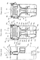
- Figure 18(A) illustrates a front view of a conductive unit in the extension tube of Fig. 13(A) ;
- Figure 18(B) illustrates a side view of the conductive unit;
- Figure 18(C) illustrates a rear view of the conductive unit.
- Figure 19 illustrates an exploded view of the conductive unit of Fig. 18(A) .
- Figure 20(A) illustrates a cross-section view taken from line I-I of Fig. 18(A) ;
- Figure 20(B) illustrates a cross-section view taken from line II-II of Fig. 18(A) ;
- Figure 20(C) illustrates a cross-section view taken from line III-III of Fig. 18(A) .
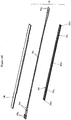
- Figure 21 illustrates lead wires in a cover plate of the conductive unit of Fig. 18(A) ; and Figure 22 illustrates a transverse cross-section view of the first connecting pipe unit of the extension tube of Fig. 13(A) .
- Figures 20(A) and 20(B) illustrate the cross-section views of projecting pieces 24c 2 , respectively, which will be described below.
- the conductive unit 24 includes a pair of conductive cables 24a and an elongated hollow plate 24x for housing the pair of conductive cables 24a.
- the hollow plate 24x has the support plate 24b and a cover plate 24c that are configured to contain and sandwich the pair of conductive cables 24a therebetween; and these component parts are integrated by ultrasonic welding at a time of assembling the conductive unit 24. These component parts may be integrated by an adhesive.
- the pair of conductive cables 24a and the support plate 24b are longer in length than the tube body 21; the pair of conductive cables 24a are longer in length than the support plate 24b; and the support plate 24b is longer in length than the cover plate 24c.
- Each conductive cable 24a has the lead wires 24a 1 covered with an insulating tube, and also has the pin-shaped male terminals 24a 2 and the clip-shaped female terminals 24a 3 , both of the terminals being electrically connected with both ends of the lead wires 24a 1 .
- the male terminals 24a 2 of the extension tube 20 are plugged into and electrically connected with the female terminals 11y 12 , respectively, of the vacuum cleaner body 10; and the male terminals 42a (to be described below) of the intake port body 40 are plugged into and electrically connected with the female terminals 24a 3 , respectively, of the extension tube 20 (see Fig. 23 ).
- the support plate 24b has a base portion 24b 1 having a concave transverse plane and also has a pair of hooking pieces 24b 2 provided along upper end portions of both side surfaces of the base portion 24b 1 ; and the support plate is made of an insulating resin (such as an ABS resin).
- the cover plate 24c has a base portion 24c 1 whose transverse plane is nearly m-shaped, and also has the projecting pieces 24c 2 provided on the outer surface of both end portions of the base portion 24c 1 ; and the cover plate is made of an insulating resin (such as an ABS resin).
- the pair of projecting pieces 24c 2 at the both end portions play a role of embankments (or banks) to block objects, such as dirt, from entering a space between the projecting pieces 24c 2 .
- the base portion 24c 1 has a pair of grooves 24c 11 provided along a longitudinal direction at a center of a width direction and respectively housing the pair of conductive cables 24a.
- a transverse plane of an outer surface of the base portion 24c 1 opposite to the grooves 24c 11 has an arc shape; and a transverse plane of an outer surface of the projecting piece 24c 2 also has an arc shape.
- a transverse plane of an outer surface of the pair of hooking pieces 24b 2 of the support plate 24b has an arcuate portion 24b 21 that is continuous with each arc projecting piece 24c 2 of the cover plate 24c, and also has a flat surface portion 24b 22 .
- each groove 24c 11 of the base portion 24c 1 On both sides of each groove 24c 11 of the base portion 24c 1 , a pair of ridges 24c 4 is provided along a longitudinal direction.
- the conductive unit 24 contains each of the conductive cables 24a in each groove 24c 11 of the cover plate 24c; and the support plate 24b covers the groove 24c 11 side; and then an inner surface of the support plate 24b comes in contact with the pair of ridges 24c 4 of the cover plate 24c and is ultrasonic-welded with these ridges. Instead of the ultrasonic welding, an adhesive may be used.
- the support plate 24b is longer in length than the cover plate 24c; and each conductive cable 24a is longer in length than the support plate 24b, with the result that a part of both ends of each conductive cable 24a is exposed to the outside while being supported by the support plate 24b.
- the conductive cables 24a are referred to as the pair of conductive cables, but are not limited to this.
- only one conductive cable may be used.
- the one cable may have two conductive cables inside, allowing the two cables to be one cable. This allows the one cable to be laid through one of the two grooves 24c 11 (see Fig. 20 ).
- the conductive unit 24 is inserted into the tube body 21; and then the pair of male terminals 24a 2 of the conductive unit 24 is incorporated (or inserted) into the first connecting pipe unit 22, and the pair of female terminals 24a 3 of the conductive unit 24 is incorporated (or inserted) into the second connecting pipe unit 23.
- the pair of male terminals 24a 2 is inserted into the connecting pipe body 22a of the first connecting pipe unit 22, is drawn from the drawing port 22a 21 to the outside, and is fixed to the rib structure 22a 22 .
- the pair of male terminals 24a 2 fixed to the rib structure 22a 22 projects from the rib structure 22a 22 in a longitudinal direction.
- one end of the pair of hooking pieces 24b 2 of the support plate 24b of the conductive unit 24 is placed on the pair of receiving pieces 22a 11 of the connecting pipe body 22a.
- Portions facing inner surfaces of the tube body 21 and the first and second connecting pipe units 22 and 23-i.e., outer surfaces of the pair of hooking pieces 24b 2 of the support plate 24b and an outer surface of the cover plate 24c-in the conductive unit 24 are configured to have an arc shape so that the conductive unit 24 can lay along the inner surfaces of the tube body 21 and the first and second connecting pipe units 22 and 23.
- the fragment 22b and the cover 22c are attached to the connecting pipe body 22a; and the fixed portion 22a 1 of the connecting pipe body 22a is inserted into one end of the tube body 21 and is fixed thereto with an adhesive.
- the positioning convex portion 22a 12 of the first connecting pipe unit 22 engages with one of the notches 21n of the tube body 21 so as to position the positioning convex portion.
- the support plate 24b has the shape like the letter "U” whose transverse plane is shallow; and a transverse plane of the cover plate 24c has the shape like the letter "W"; and these component parts each are provided with a rib in a longitudinal direction.
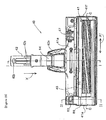
- Figure 23 illustrates a bottom view of an intake port body of the electric vacuum cleaner in accordance with Embodiment 1;
- Figure 24 illustrates a side view of the intake port body illustrated in Fig. 23 .
- Figure 25 illustrates a cross-section view of the intake port body taken from line I-I of Fig. 23 ;
- Figure 26 illustrates a cross-section view of the intake port body taken from line II-II of Fig. 23 .
- the intake port body 40 includes the following component parts: a bottom plate 41a; a top plate 41b opposed to the bottom plate 41a; a front plate 41c and a rear plate 41d that are respectively placed at the front and at the back in a moving direction (in a direction of an X arrow indicated in Fig. 23 ); and a left plate 41e and a right plate 41f that are respectively placed on the left and on the right of the top plate 41b in the moving direction.
- the intake port body 40 includes the following component parts: an intake port 41 that is provided to the bottom plate 41a and extends in a right-and-left direction (in a direction of an A1 arrow); a connecting pipe 42 connected to the rear side of the intake port 41 through a connecting shaft 42x; a rotary brush 43 rotatably attached around an axis extending in a right-and-left direction in the intake port 41; a suction channel 16 connecting the intake port 41 to the connecting pipe 42 (see Fig. 25 ); a motor for rotary brush 44 driving the rotary brush 43 (see Fig. 26 ); a brush cover 80 covering a left end of the rotary brush 43 (as illustrated in Fig. 23 ); and a lifting detecting device 47 and wheels 54, all of which being attached to the bottom plate 41a.
- a motor output gear 50 fixed to a motor output shaft 46 of the motor for rotary brush 44 is fastened to a gear 58b attached to the rotary brush 43 with a timing belt 48.
- the lifting detecting device 47 has the following component parts: a swinging lever having a wheel; a switch body swingably supporting the swing lever; and a torsion coil spring biasing the swinging lever toward the bottom side; and the switch body is connected with a circuit board for rotary brush-driving motor contained in the bottom plate 41a; and the wheel of the swinging lever is downwardly exposed from the bottom plate 41a to the outside.
- the lifting detecting device 47 When the intake port body 40 is lifted and spaced away from the floor, the lifting detecting device 47 is triggered and forces to stop the operation of the motor for rotary brush 44.
- This intake port body 40 has a pair of lead wires that is placed therein and is electrically connected with the motor for rotary brush 44 and the lifting detecting device 47; and the pair of lead wires are electrically connected with the pair of pin-shaped male terminals 42a, respectively, the male terminals being provided to the connecting pipe 42.
- the connecting pipe 42 has at its end a locking concave portion 42b.
- the intake port body 40 configured as described above is detachably connected with the second connecting pipe unit 23 of the extension tube 20.
- the pair of male terminals 42b of the intake port body 40 are respectively inserted into the pair of female terminals 24a 3 of the extension tube 20, and are electrically connected therewith; and the locking nail 23c 3 of the locking member 23c of the extension tube 20 detachably locks into the locking concave portion 42b of the intake port body 40 (see Fig. 1 , Fig. 13 , and Fig. 14 ).
- the extension tube 20 provided with the first and second connecting pipe units 22 and 23 at both ends of the tube body 21 has been described in the first embodiment. However, the first and second connecting pipe units 22 and 23 may be omitted. In such a case, the extension tube is configured such that the male terminal and the female terminal at both ends of the conductive unit 24 are fixed to both interior ends of the tube body.
- extension tube for an electric stick vacuum cleaner has been described in the first embodiment.
- the extension tube according to the present invention is also applicable to an electric canister vacuum cleaner.
- the extension tube for the electric vacuum cleaner comprises a tube body and a conductive unit provided so as to be laid in the tube body, wherein the conductive unit includes conductive cables and a hollow plate that contains the conductive cables.
- the extension tube for the electric vacuum cleaner according to the present invention may have configurations described below, and these configurations may be combined with one another as appropriate.
- the present invention is applicable to an extension tube for an electric vacuum cleaners such as stick vacuum cleaners and canister vacuum cleaners.
Landscapes
- Engineering & Computer Science (AREA)
- Mechanical Engineering (AREA)
- Electric Vacuum Cleaner (AREA)
- Filters For Electric Vacuum Cleaners (AREA)
Applications Claiming Priority (2)
| Application Number | Priority Date | Filing Date | Title |
|---|---|---|---|
| JP2016219072 | 2016-11-09 | ||
| PCT/JP2017/004585 WO2018087937A1 (fr) | 2016-11-09 | 2017-02-08 | Tube d'extension pour aspirateur électrique |
Publications (2)
| Publication Number | Publication Date |
|---|---|
| EP3539436A1 true EP3539436A1 (fr) | 2019-09-18 |
| EP3539436A4 EP3539436A4 (fr) | 2019-11-06 |
Family
ID=62110553
Family Applications (1)
| Application Number | Title | Priority Date | Filing Date |
|---|---|---|---|
| EP17869541.7A Withdrawn EP3539436A4 (fr) | 2016-11-09 | 2017-02-08 | Tube d'extension pour aspirateur électrique |
Country Status (8)
| Country | Link |
|---|---|
| US (1) | US20190208974A1 (fr) |
| EP (1) | EP3539436A4 (fr) |
| JP (1) | JPWO2018087937A1 (fr) |
| KR (1) | KR20190025978A (fr) |
| CN (1) | CN109952052A (fr) |
| SG (1) | SG11201900807QA (fr) |
| TW (1) | TW201817359A (fr) |
| WO (1) | WO2018087937A1 (fr) |
Families Citing this family (28)
| Publication number | Priority date | Publication date | Assignee | Title |
|---|---|---|---|---|
| GB201616598D0 (en) * | 2016-09-30 | 2016-11-16 | Grey Technology Limited | Cleaning head for a vacuum cleaner |
| EP3641609B1 (fr) * | 2017-06-19 | 2022-11-09 | Techtronic Floor Care Technology Limited | Appareil de nettoyage de surface |
| JP1625432S (fr) * | 2018-05-29 | 2019-02-25 | ||
| USD912344S1 (en) * | 2018-08-29 | 2021-03-02 | Samsung Electronics Co., Ltd. | Cleaner |
| KR102099683B1 (ko) * | 2018-08-30 | 2020-04-10 | 삼성전자주식회사 | 진공청소기 |
| KR102071945B1 (ko) * | 2018-08-30 | 2020-01-31 | 삼성전자주식회사 | 청소기 |
| US11903553B2 (en) * | 2018-11-06 | 2024-02-20 | H-P Products, Inc. | Vacuum hose having an integrated switch |
| USD933320S1 (en) | 2019-05-13 | 2021-10-12 | Bissell Inc. | Vacuum cleaner |
| USD977770S1 (en) * | 2019-06-14 | 2023-02-07 | Sharkninja Operating Llc | Hand vacuum |
| JP2021003271A (ja) * | 2019-06-26 | 2021-01-14 | 日立グローバルライフソリューションズ株式会社 | 電気掃除機 |
| USD1038556S1 (en) * | 2019-09-20 | 2024-08-06 | Yihu Zhuo | Vacuum |
| JP7365853B2 (ja) * | 2019-10-29 | 2023-10-20 | シャープ株式会社 | 電気掃除機 |
| JP7461729B2 (ja) * | 2019-10-29 | 2024-04-04 | シャープ株式会社 | 電気掃除機 |
| DE102019129823A1 (de) * | 2019-11-05 | 2021-05-06 | Festool Gmbh | Verbindungsanordnung für eine handgeführte Werkzeugmaschine und handgeführte Werkzeugmaschine |
| CN111084575A (zh) * | 2019-12-31 | 2020-05-01 | 杰之深(苏州)科技有限公司 | 一种吸尘器主机 |
| KR102249933B1 (ko) * | 2020-05-15 | 2021-05-10 | 광동하이텍 주식회사 | 전선내장형 텔레스코픽 연장관 |
| CN113940581B (zh) * | 2020-07-15 | 2023-11-07 | 莱克电气股份有限公司 | 一种手持式吸尘装置及吸尘设备 |
| USD952970S1 (en) * | 2020-07-16 | 2022-05-24 | Sharkninja Operating Llc | Vacuum cleaner |
| USD932122S1 (en) * | 2020-09-10 | 2021-09-28 | Suzhou Sweep Electric Appliance Co., Ltd. | Vacuum cleaner |
| USD922010S1 (en) * | 2020-11-16 | 2021-06-08 | Dongguan Sogoode Computer System Co., Ltd | Vacuum cleaner |
| JP1696401S (fr) * | 2020-12-24 | 2021-10-04 | ||
| CN215077997U (zh) * | 2021-02-02 | 2021-12-10 | 深圳市小摩科技有限公司 | 一种伸缩导电管 |
| USD946221S1 (en) * | 2021-02-08 | 2022-03-15 | Shenzhen Shermon Technology Co., Limited | Vacuum cleaner |
| USD973987S1 (en) * | 2021-02-08 | 2022-12-27 | Shenzhen Shermon Technology Co., Limited | Handheld vacuum cleaner |
| US11744423B2 (en) * | 2021-04-27 | 2023-09-05 | Shenzhen Shermon Technology Co., Limited | Telescopic conductive tube |
| KR102383709B1 (ko) | 2021-08-18 | 2022-04-08 | (주)코넥 | 지진재해에 대응 가능한 안전 도어장치 |
| USD1030162S1 (en) * | 2021-09-16 | 2024-06-04 | Techtronic Cordless Gp | Vacuum cleaner |
| USD1078201S1 (en) * | 2024-04-23 | 2025-06-03 | BSH Hausgeräte GmbH | Handheld vacuum cleaner |
Family Cites Families (7)
| Publication number | Priority date | Publication date | Assignee | Title |
|---|---|---|---|---|
| JPH1085161A (ja) * | 1996-09-13 | 1998-04-07 | Mitsubishi Electric Corp | 電気掃除機 |
| JP3748365B2 (ja) * | 2000-06-21 | 2006-02-22 | 矢崎総業株式会社 | 電線配索構造及び電線配索方法 |
| JP3673710B2 (ja) * | 2000-11-17 | 2005-07-20 | 株式会社イトーキクレビオ | 天板の後端縁における配線受け樋装置 |
| JP2004173363A (ja) * | 2002-11-18 | 2004-06-17 | Panahome Corp | 配線構造 |
| JP5356680B2 (ja) * | 2007-12-27 | 2013-12-04 | 株式会社岡村製作所 | 家具の配線構造 |
| CN201417909Y (zh) * | 2009-05-22 | 2010-03-03 | 肖双喜 | 一种隔离式线槽、管 |
| JP2012249699A (ja) | 2011-05-31 | 2012-12-20 | Hitachi Appliances Inc | 電気掃除機 |
-
2017
- 2017-02-08 EP EP17869541.7A patent/EP3539436A4/fr not_active Withdrawn
- 2017-02-08 US US16/325,695 patent/US20190208974A1/en not_active Abandoned
- 2017-02-08 KR KR1020197003285A patent/KR20190025978A/ko not_active Abandoned
- 2017-02-08 WO PCT/JP2017/004585 patent/WO2018087937A1/fr not_active Ceased
- 2017-02-08 SG SG11201900807QA patent/SG11201900807QA/en unknown
- 2017-02-08 JP JP2018550018A patent/JPWO2018087937A1/ja active Pending
- 2017-02-08 CN CN201780047300.7A patent/CN109952052A/zh active Pending
- 2017-08-09 TW TW106126990A patent/TW201817359A/zh unknown
Also Published As
| Publication number | Publication date |
|---|---|
| KR20190025978A (ko) | 2019-03-12 |
| TW201817359A (zh) | 2018-05-16 |
| SG11201900807QA (en) | 2019-02-27 |
| EP3539436A4 (fr) | 2019-11-06 |
| CN109952052A (zh) | 2019-06-28 |
| WO2018087937A1 (fr) | 2018-05-17 |
| US20190208974A1 (en) | 2019-07-11 |
| JPWO2018087937A1 (ja) | 2019-09-26 |
Similar Documents
| Publication | Publication Date | Title |
|---|---|---|
| EP3539436A1 (fr) | Tube d'extension pour aspirateur électrique | |
| EP3539437A1 (fr) | Tube d'extension pour aspirateur électrique | |
| JP7510387B2 (ja) | 電気掃除機 | |
| JP6849400B2 (ja) | 電気掃除機 | |
| KR101119615B1 (ko) | 진공청소기 | |
| JP6886787B2 (ja) | 電気機器および電気掃除機 | |
| EP2392244B1 (fr) | Aspirateur portatif de type bâton | |
| KR101224595B1 (ko) | 핸디-스틱형 진공청소기 | |
| CN204445685U (zh) | 电动吸尘器 | |
| EP2529652B1 (fr) | Appareil de nettoyage | |
| JP7414638B2 (ja) | 電気掃除機 | |
| JP6572366B2 (ja) | 吸込口体およびそれを備えた電気掃除機 | |
| JP7357508B2 (ja) | 電気掃除機 | |
| JP2025510258A (ja) | 改善されたシーリングを有するユーザインターフェースを備えた掃除機 | |
| KR20180079166A (ko) | 로봇 청소기 | |
| JP5275732B2 (ja) | 電気掃除機 | |
| EP3622873B1 (fr) | Appareil de séparation à cyclone et aspirateur | |
| JP5100562B2 (ja) | 回転清掃体、吸込口体および電気掃除機 | |
| KR100812612B1 (ko) | 핸디청소기 일체형 진공청소기 | |
| JP2019202049A (ja) | 電気掃除機 | |
| HK40030238B (zh) | 电动吸尘器 | |
| JP2019018054A (ja) | 吸込口体およびそれを備えた電気掃除機 | |
| KR20060131418A (ko) | 진공청소기의 헤드 | |
| JP2006334218A (ja) | 電気掃除機 | |
| KR20060128100A (ko) | 진공청소기의 헤드 |
Legal Events
| Date | Code | Title | Description |
|---|---|---|---|
| STAA | Information on the status of an ep patent application or granted ep patent |
Free format text: STATUS: THE INTERNATIONAL PUBLICATION HAS BEEN MADE |
|
| PUAI | Public reference made under article 153(3) epc to a published international application that has entered the european phase |
Free format text: ORIGINAL CODE: 0009012 |
|
| STAA | Information on the status of an ep patent application or granted ep patent |
Free format text: STATUS: REQUEST FOR EXAMINATION WAS MADE |
|
| 17P | Request for examination filed |
Effective date: 20190121 |
|
| AK | Designated contracting states |
Kind code of ref document: A1 Designated state(s): AL AT BE BG CH CY CZ DE DK EE ES FI FR GB GR HR HU IE IS IT LI LT LU LV MC MK MT NL NO PL PT RO RS SE SI SK SM TR |
|
| AX | Request for extension of the european patent |
Extension state: BA ME |
|
| A4 | Supplementary search report drawn up and despatched |
Effective date: 20191009 |
|
| RIC1 | Information provided on ipc code assigned before grant |
Ipc: A47L 9/24 20060101AFI20191002BHEP |
|
| DAV | Request for validation of the european patent (deleted) | ||
| DAX | Request for extension of the european patent (deleted) | ||
| STAA | Information on the status of an ep patent application or granted ep patent |
Free format text: STATUS: THE APPLICATION IS DEEMED TO BE WITHDRAWN |
|
| 18D | Application deemed to be withdrawn |
Effective date: 20210901 |