EP3539584A1 - Mikroaxialpumpe zur unterstützung der blutzirkulation (varianten) - Google Patents
Mikroaxialpumpe zur unterstützung der blutzirkulation (varianten) Download PDFInfo
- Publication number
- EP3539584A1 EP3539584A1 EP17870134.8A EP17870134A EP3539584A1 EP 3539584 A1 EP3539584 A1 EP 3539584A1 EP 17870134 A EP17870134 A EP 17870134A EP 3539584 A1 EP3539584 A1 EP 3539584A1
- Authority
- EP
- European Patent Office
- Prior art keywords
- shaft
- half coupling
- coupling
- housing
- pump unit
- Prior art date
- Legal status (The legal status is an assumption and is not a legal conclusion. Google has not performed a legal analysis and makes no representation as to the accuracy of the status listed.)
- Withdrawn
Links
Images




Classifications
-
- A—HUMAN NECESSITIES
- A61—MEDICAL OR VETERINARY SCIENCE; HYGIENE
- A61M—DEVICES FOR INTRODUCING MEDIA INTO, OR ONTO, THE BODY; DEVICES FOR TRANSDUCING BODY MEDIA OR FOR TAKING MEDIA FROM THE BODY; DEVICES FOR PRODUCING OR ENDING SLEEP OR STUPOR
- A61M60/00—Blood pumps; Devices for mechanical circulatory actuation; Balloon pumps for circulatory assistance
- A61M60/10—Location thereof with respect to the patient's body
- A61M60/122—Implantable pumps or pumping devices, i.e. the blood being pumped inside the patient's body
- A61M60/126—Implantable pumps or pumping devices, i.e. the blood being pumped inside the patient's body implantable via, into, inside, in line, branching on, or around a blood vessel
- A61M60/13—Implantable pumps or pumping devices, i.e. the blood being pumped inside the patient's body implantable via, into, inside, in line, branching on, or around a blood vessel by means of a catheter allowing explantation, e.g. catheter pumps temporarily introduced via the vascular system
-
- A—HUMAN NECESSITIES
- A61—MEDICAL OR VETERINARY SCIENCE; HYGIENE
- A61M—DEVICES FOR INTRODUCING MEDIA INTO, OR ONTO, THE BODY; DEVICES FOR TRANSDUCING BODY MEDIA OR FOR TAKING MEDIA FROM THE BODY; DEVICES FOR PRODUCING OR ENDING SLEEP OR STUPOR
- A61M60/00—Blood pumps; Devices for mechanical circulatory actuation; Balloon pumps for circulatory assistance
- A61M60/20—Type thereof
- A61M60/205—Non-positive displacement blood pumps
- A61M60/216—Non-positive displacement blood pumps including a rotating member acting on the blood, e.g. impeller
- A61M60/237—Non-positive displacement blood pumps including a rotating member acting on the blood, e.g. impeller the blood flow through the rotating member having mainly axial components, e.g. axial flow pumps
-
- A—HUMAN NECESSITIES
- A61—MEDICAL OR VETERINARY SCIENCE; HYGIENE
- A61M—DEVICES FOR INTRODUCING MEDIA INTO, OR ONTO, THE BODY; DEVICES FOR TRANSDUCING BODY MEDIA OR FOR TAKING MEDIA FROM THE BODY; DEVICES FOR PRODUCING OR ENDING SLEEP OR STUPOR
- A61M60/00—Blood pumps; Devices for mechanical circulatory actuation; Balloon pumps for circulatory assistance
- A61M60/10—Location thereof with respect to the patient's body
- A61M60/122—Implantable pumps or pumping devices, i.e. the blood being pumped inside the patient's body
- A61M60/165—Implantable pumps or pumping devices, i.e. the blood being pumped inside the patient's body implantable in, on, or around the heart
- A61M60/17—Implantable pumps or pumping devices, i.e. the blood being pumped inside the patient's body implantable in, on, or around the heart inside a ventricle, e.g. intraventricular balloon pumps
-
- A—HUMAN NECESSITIES
- A61—MEDICAL OR VETERINARY SCIENCE; HYGIENE
- A61M—DEVICES FOR INTRODUCING MEDIA INTO, OR ONTO, THE BODY; DEVICES FOR TRANSDUCING BODY MEDIA OR FOR TAKING MEDIA FROM THE BODY; DEVICES FOR PRODUCING OR ENDING SLEEP OR STUPOR
- A61M60/00—Blood pumps; Devices for mechanical circulatory actuation; Balloon pumps for circulatory assistance
- A61M60/40—Details relating to driving
- A61M60/403—Details relating to driving for non-positive displacement blood pumps
- A61M60/408—Details relating to driving for non-positive displacement blood pumps the force acting on the blood contacting member being mechanical, e.g. transmitted by a shaft or cable
- A61M60/411—Details relating to driving for non-positive displacement blood pumps the force acting on the blood contacting member being mechanical, e.g. transmitted by a shaft or cable generated by an electromotor
- A61M60/414—Details relating to driving for non-positive displacement blood pumps the force acting on the blood contacting member being mechanical, e.g. transmitted by a shaft or cable generated by an electromotor transmitted by a rotating cable, e.g. for blood pumps mounted on a catheter
-
- A—HUMAN NECESSITIES
- A61—MEDICAL OR VETERINARY SCIENCE; HYGIENE
- A61M—DEVICES FOR INTRODUCING MEDIA INTO, OR ONTO, THE BODY; DEVICES FOR TRANSDUCING BODY MEDIA OR FOR TAKING MEDIA FROM THE BODY; DEVICES FOR PRODUCING OR ENDING SLEEP OR STUPOR
- A61M60/00—Blood pumps; Devices for mechanical circulatory actuation; Balloon pumps for circulatory assistance
- A61M60/40—Details relating to driving
- A61M60/403—Details relating to driving for non-positive displacement blood pumps
- A61M60/422—Details relating to driving for non-positive displacement blood pumps the force acting on the blood contacting member being electromagnetic, e.g. using canned motor pumps
-
- A—HUMAN NECESSITIES
- A61—MEDICAL OR VETERINARY SCIENCE; HYGIENE
- A61M—DEVICES FOR INTRODUCING MEDIA INTO, OR ONTO, THE BODY; DEVICES FOR TRANSDUCING BODY MEDIA OR FOR TAKING MEDIA FROM THE BODY; DEVICES FOR PRODUCING OR ENDING SLEEP OR STUPOR
- A61M60/00—Blood pumps; Devices for mechanical circulatory actuation; Balloon pumps for circulatory assistance
- A61M60/80—Constructional details other than related to driving
- A61M60/802—Constructional details other than related to driving of non-positive displacement blood pumps
- A61M60/804—Impellers
-
- A—HUMAN NECESSITIES
- A61—MEDICAL OR VETERINARY SCIENCE; HYGIENE
- A61M—DEVICES FOR INTRODUCING MEDIA INTO, OR ONTO, THE BODY; DEVICES FOR TRANSDUCING BODY MEDIA OR FOR TAKING MEDIA FROM THE BODY; DEVICES FOR PRODUCING OR ENDING SLEEP OR STUPOR
- A61M60/00—Blood pumps; Devices for mechanical circulatory actuation; Balloon pumps for circulatory assistance
- A61M60/80—Constructional details other than related to driving
- A61M60/802—Constructional details other than related to driving of non-positive displacement blood pumps
- A61M60/804—Impellers
- A61M60/806—Vanes or blades
-
- A—HUMAN NECESSITIES
- A61—MEDICAL OR VETERINARY SCIENCE; HYGIENE
- A61M—DEVICES FOR INTRODUCING MEDIA INTO, OR ONTO, THE BODY; DEVICES FOR TRANSDUCING BODY MEDIA OR FOR TAKING MEDIA FROM THE BODY; DEVICES FOR PRODUCING OR ENDING SLEEP OR STUPOR
- A61M60/00—Blood pumps; Devices for mechanical circulatory actuation; Balloon pumps for circulatory assistance
- A61M60/80—Constructional details other than related to driving
- A61M60/802—Constructional details other than related to driving of non-positive displacement blood pumps
- A61M60/81—Pump housings
-
- A—HUMAN NECESSITIES
- A61—MEDICAL OR VETERINARY SCIENCE; HYGIENE
- A61M—DEVICES FOR INTRODUCING MEDIA INTO, OR ONTO, THE BODY; DEVICES FOR TRANSDUCING BODY MEDIA OR FOR TAKING MEDIA FROM THE BODY; DEVICES FOR PRODUCING OR ENDING SLEEP OR STUPOR
- A61M60/00—Blood pumps; Devices for mechanical circulatory actuation; Balloon pumps for circulatory assistance
- A61M60/80—Constructional details other than related to driving
- A61M60/802—Constructional details other than related to driving of non-positive displacement blood pumps
- A61M60/818—Bearings
- A61M60/825—Contact bearings, e.g. ball-and-cup or pivot bearings
-
- A—HUMAN NECESSITIES
- A61—MEDICAL OR VETERINARY SCIENCE; HYGIENE
- A61M—DEVICES FOR INTRODUCING MEDIA INTO, OR ONTO, THE BODY; DEVICES FOR TRANSDUCING BODY MEDIA OR FOR TAKING MEDIA FROM THE BODY; DEVICES FOR PRODUCING OR ENDING SLEEP OR STUPOR
- A61M60/00—Blood pumps; Devices for mechanical circulatory actuation; Balloon pumps for circulatory assistance
- A61M60/40—Details relating to driving
- A61M60/403—Details relating to driving for non-positive displacement blood pumps
- A61M60/419—Details relating to driving for non-positive displacement blood pumps the force acting on the blood contacting member being permanent magnetic, e.g. from a rotating magnetic coupling between driving and driven magnets
Definitions
- This group of inventions relate to medical equipment in general, and in particular, to devices for pumping single-phase or multi-phase fluids without altering their properties (e.g. pump-assisted blood circulation at various surgical interventions) and may be used as an auxiliary device with cardiac decompensation or as a principal pump in systems of assisted blood circulation.
- Blood is a polydisperse system (a suspension of formative elements (erythrocytes, thrombocytes, leucocytes) in the plasm).
- the blood is permanently circulating in the body within a closed system that prevents its interaction with environment and, hence, preserves its properties.
- the existing technical level makes us believe that development of assisted blood circulation is focused on miniature implanted pumps that ensure physiological blood flow with minimal surgical intrusion.
- Such pumps are designed on the basis of a given physiological pressure difference and heart flow parameters.
- the miniature pumps fall into three classes: axial pumps, centrifugal pumps, and diagonal pumps.
- the axial and diagonal pumps are blood support devices of smaller dimensions but, with equal starting parameters, a centrifugal pump provides required flow at lower rotation velocity of movable parts, thus, resulting in less blood trauma.
- the design of used miniature axial pumps typically consists of a cylinder tube with an incorporated impeller and support elements.
- the requirement for smaller dimensions and, in particular, implantability via the cardiovascular system leads to an extremely high speed of the impeller in order to reach physiological parameters of blood circulation.
- High rotation velocity inevitably leads to higher blood trauma and limits both the motor resource and its useful duration inside the body.
- Such pumps are used for short periods (up to 15 days) in critical invasions of limited scale surgery. Devices of this type are introduced in the body via large blood vessels and exclude transthoracic surgery.
- Such pumps are introduced via large vessels in the body (such as the vein below the groin) and conducted to a ventricle by a flexible guide.
- the size of vessels poses significant dimensional restraints on the device.
- the device needs to be less than 10 mm in diameter.
- An option with a flexible main shaft does not require miniature motors inside the body and permits a simpler design.
- a complex vessel configuration e.g. in the curved area between the descending aorta and the aortic valve
- using a flexible shaft poses restrictions on motor operation modes as there is a risk of shaft jamming due to its length and friction against the walls.
- the invention ( US20120029265 A1 , published on 02.02.2012) is a pump with one or several stators. With the help of a guide the pump is introduced through larger vessels into the ventricle cavity. It is positioned and fixed by way of the stent with shape memory. The motor coils are place directly inside the ventricle or the ascending aorta making it possible to do without a flexible shaft on account of a more complex design.
- the principle drawbacks of this design are the need for high velocity of the impeller (from 20 000 to 60 000 rpm) in order to supply the necessary physiological flow and small gaps between the housing and the rotor (about 0.1 mm). These factors contribute to a significant hematolysis on account of high shearing stress inside the pump flow channel.
- a closely analogous device is the one for assisted blood circulation ( US6176822 B1 , published on 23.01.2001) that represents a miniature pump unit with a tiny electrical motor.
- the motor shaft has a cantilever hold on one side (proximal). On the other, distal side the motor shaft goes through a sleeve bearing and a seal ring.
- the motor shaft terminates with an impeller.
- the driving part is located above the aortal valve.
- the pump is introduced in the ventricle cavity by a flexible guide through larger vessels.
- This group of inventions serves to resolve the technical problem arising from considerably changed parameters of pumped single-phased and multi-phased fluids (e.g. blood) including blood trauma, stagnation and recirculation zones.
- pumped single-phased and multi-phased fluids e.g. blood
- blood trauma e.g. blood trauma, stagnation and recirculation zones.
- the technical effect of at least one embodiment of the present technology as disclosed herein is an reduction of blood trauma through lower perturbance in the flow inside the pump channel, lower velocity of impeller rotation, no need for local lubrication, and exclusion of power unit motor jamming.
- the additional technical effect of at least one embodiment of the present technology as disclosed herein is intact skin (avoidance of invasion).
- a blood pumping device as described herein comprises a multi-stage pump unit and a power unit.
- the multi-stage pump unit having: a housing, a spacer shaft, at least two axial stages containing curved vane impellers placed on the spacer shaft inside the housing and containing a stator placed on the spacer shaft inside the housing.
- the power unit having: a hermetic housing, a motor, located inside said housing, and a motor-driven main shaft.
- the impeller of the multi-stage pump unit is connected to the main shaft via a noncontact magnetic coupling, the noncontact magnetic coupling having: an external driving half coupling set on the main shaft and an internal driven half coupling located of an end mount of the impeller of the second axial - stage of the multi-stage pump unit.
- the stator has at least three straighteners and one of them being an inflow straightener.
- the vanes of the inflow straightener are aligned along an axis of the spacer shaft and/or at an angle to said axis.
- the number of curved vanes of at least one impeller is different from the number of vanes of at least one straightener of the stator.
- a blood pumping device as described herein comprises a multi-stage pump unit and a power unit.
- the multi-stage pump unit includes at least two axial stages located on a spacer shaft inside a multi-stage pump unit housing, at least two axial stages containing impellers having curved vanes, and a stator.
- the power unit which is located outside the patient's body, consists of a housing, an motor and a motor-driven main shaft.
- the main shaft transmits the torque to the spacer shaft of the pump unit by a flexible transmission shaft and a magnetic coupling via a magnetic field.
- the magnetic coupling having an external driving half coupling set on the main shaft of the power unit, and an internal driven half coupling located of an end side of a mount of the impeller of the second axial stage of the multi-stage pump unit.
- the flexible transmission shaft is located inside the patient's body with a terminal magnetic half couplings fixed on each end of it.
- the first terminal half coupling has a magnetic contact with the internal driven half coupling of the pump unit and the second terminal half coupling has a magnetic contact with the external driving half coupling of the power unit.
- the spacer shaft is located into at least one pass -through and at least one terminal bearing support.
- sleeve bearings and/or roller bearings are used as bearings.
- the curved vanes of the impellers of the multi-stage pump unit have the same or different profiles.
- the flexible transmission shaft is supported by sleeve and/or roller bearings at equal or varied intervals along the shaft axis, the flexible transmission shaft is located inside the hollow flexible broach.
- the flexible shaft made in the form of a steel string with a round cross section.
- the external driving half coupling is in the form of a pulley with permanent magnets integrated inside it and the internal driven half coupling contains permanent magnets integrated in the mount of impeller of the second axial -stage of the multi-stage pump unit.
- the first terminal half coupling is in the form of a pulley with permanent magnets and the second terminal half coupling is in the form of a bushing with permanent magnets integrated in its mount.
- the pulley of the first terminal half coupling and the bushing of the second terminal half coupling are located in respective hermetic housings with an adaptor cover rigidly connected to the hollow a flexible broach.
- the external diameter of the housing of the multi-stage pump unit is smaller than the diameter of large blood vessels.
- the use of two stages of the axial pump serves to reduce motor velocity that leads to smaller shearing stress in the gaps between the pump housing and the impellers, thus, benefitting the flow of essential blood elements (erythrocytes, thrombocytes, leucocytes) through the pump channel.
- essential blood elements erythrocytes, thrombocytes, leucocytes
- a two-stage pump needs to produce up to 15 000 - 18 000 rpm.
- a straightener is put inside its entrance for better flow attraction onto the impeller vanes.
- a vane profile for the straightener is selected on the basis of the flow behavior at the entrance to the axial pump.
- the multi-stage pump is designed in such a way so that the number of curved vanes of at least one impeller differs from the number of vanes of at least one straightener of the stator. This serves for reduction of flow disturbance inside the pump channel and less blood trauma as compared to a design with divisible or equal numbers of impeller vanes and stator elements.
- the distinguishing feature of the blood pumping device having a pump unit inside the patient's body and the power unit outside it, is that it fully excludes environment particles (blood) getting onto the friction surfaces: sleeve bearing - flexible shaft. This preserves sterility and reduces mechanical blood damage. The rotating torque is communicated bypassing the skin and does not change the environment (blood).
- the perfectly hermetic noncontact flexible transmission preserves the sterile location of the pump inside the ventricle cavity and excludes the necessity to place in the body such power unit elements as stator coil.
- This embodiment of the invention provides an opportunity of replacing the power unit without re-implantation (in cases of wear or failure of the motor). This prolongs the useful life of pump operation, reduces the weight and volume of the transplant and excludes thermal effect on blood from heated stator coils.
- the current invention belongs to the group of axial pumps for blood circulation and may be used as an ancillary device with deficient heart function or as the principal pump in systems of assisted blood circulation.
- This microaxial pump belongs to the group of axial pumps based on power interaction between the vane and the flow around it.
- the flow of the liquid is parallel to the rotation axis of the impeller and does not change its direction after going through the pump channel.
- a preferable option for such pumps is to use the principle of magnetic coupling to partition the blood side from the drive. This allows maximum restriction of blood contacting surfaces. A compact design facilitates its insertion into larger vessels.
- a microaxial pump with a magnetic coupling for blood circulation contains inside its housing a power unit and a multi-stage pump unit with sequential impellers with curved vanes and a stator on a spacer shaft.
- the pump unit is connected to a blood inlet.
- the power unit is made with opportunity to transmit the rotating torque to the spacer shaft of the pump unit.
- the each package of axial stages includes impeller of the first axial -stage or impeller of the second axial -stage with curved vanes and a stator.
- the impellers are press fitted on the spacer shaft or hermetically glued inside the housing of the pump unit in the form of a bushing.
- the stator at the entrance to the pump includes at least one inflow straightener of the incoming flow with a calculated profile of vanes and at least two straighteners with a calculated profile of vanes.
- the stator employs direct radial vanes in the inflow straightener of the incoming flow in order to ensure axial admission of the work fluid to the next axial stage impeller.
- the stator is set on the spacer shaft with the help of at least one open-type and at least one terminal bearing, which may be of sleeve and/or roller types.
- the blood pumping device with the noncontact magnetic coupling (the microaxial pump with the noncontact magnetic coupling for blood circulation is the same).
- the blood pumping device comprises a multi-stage pump unit and a power unit with hermetic housing 2 and a main shaft.
- the hermetic housing 2 of the power unit via cover 12 of the power unit ( figure 2 ) connects to a broach 1, which is a hollow tube.
- the housing 2 of power unit is adjacent to an impeller 3 of the second axial stage of the multi-stage pump unit.
- the second axial stage impeller 3 is either press fitted or glued on a spacer shaft 17 (not shown on figure 1 ).
- the spacer shaft 17 passes through a first axial stage stationary straightener 4 that contains bearing support 15 with sleeve or roller bearings.
- the first axial stage impeller 5 and the second axial stage impeller 3 are fitted similarly on the spacer shaft 17.
- a flexible insert 7 representing a flexible hollow thin-walled tube.
- the flexible insert 7 has a terminal blood inlet 8 press fitted or glued on it.
- the terminal blood inlet 8 is the stiff tube-like element perforated on edge with a distal rounded tip.
- a housing of a flow-through part with a second axial stage straightener is dismantled.
- the blood inlet that takes in the fluid has the form of hollow cylindrical flexible insert 7. It connects to terminal blood inlet 8 in the form of a stiff tube perforated on its edge with a distal rounded tip, a two-stage pump unit and a power unit.
- the terminal blood inlet 8 is connected to a housing of a flow-through part 110 by means of the flexible insert 7 attached to external surface or internal surface of the housing of the flow-through part 110.
- the flexible insert 7 is glued or soldered to the housing of the flow-through part 110.
- a second axial stage straightener 11 is glued, soldered or press fitted to the housing of the flow-through part 110 on its external surface or internal surface.
- the second axailstage straightener 11 constitutes a hollow, thin-walled tube of variable diameter or constant diameter aligned with pump axis with exit holes for fluid. Further on, the straightener 11 of the second axial stage is press fitted or otherwise connected to the housing 2 of the power unit.
- the power unit contains a motor 9 and a magnetic half coupling 10 transmitting rotation torque from the motor 9 by way of magnetic field on to the second axial stage impeller 3 and the first axial stage impeller 5.
- the first axial stage impeller 5 and the second axial stage impeller 3 are located on the spacer shaft 17 (not shown on figure 2 ).
- Stationary support for the spacer shaft 17 is provided by the first axial stage straightener 4 with sleeve or roller bearings and by the inflow straightener 6 with sleeve or roller bearings.
- the first axial stage straightener 4 and the inflow straightener 6 are press fitted, glued or soldered to internal wall of the housing of the flow-through part 110, resulting as stationary (immovable) elements.
- Conducting broach 1 is attached to a motor 9 housing by means of the power unit cover 12, which is press fitted, glued or soldered into power unit housing 2.
- Work fluid comes in through the terminal blood inlet 8 and passes via the flexible insert 7 connected to the housing of flow-through part 110 ( figure 3 ).
- the flow comes to the inflow straightener 6 and gets straightened. Thanks to the vanes of the inflow straightener 6 the circumferential component of speed gets reduced and the flow itself becomes almost axial.
- the flow comes to vanes of the first axialstage impeller 5 that imparts rotation torque to the flow and pushes it onto stationary vanes of the first axial stage straightener 4, where the kinetic energy of the flow is transformed by braking against the immovable vanes into pressure energy.
- the flow comes through the second axial stage impeller 3 where it gets additional kinetic energy again from rotation that is transformed in pressure energy when passing through the holes of the second axial stage straightener 11.
- the motor 9 is located in a cylinder part of power unit housing 13.
- a bushing 14 with magnets 16 is set on the main shaft to form magnetic half coupling 10 ( figure 2 ).
- rotating torque is transmitted via the magnetic field formed between the magnets 16 of bushing 14 and the magnets in the mount of second axial stage impeller 3 located on common spacer shaft 17 ( figure 3 ).
- the first- and second- stage impellers are on common spacer shaft 17.
- the torque transmitted to the second axial stage impeller 3 is also transmitted to the first-axial stage impeller 5.
- the spacer shaft 17 is fixed in roller and sleeve bearings in stationary first axial stage straightener 4 and inflow straightener 6.
- the number of magnets in bushing 14 and the second axial stage impeller is not less than four and the magnet poles alternate.
- the number of curved vanes of at least one impeller differs from the number of vanes of at least one straightener of the stator that helps reduce blood trauma.
- first axial stage 5 and second axial stage 3 impellers in both embodiments are determined by mathematic models based on physiological parameters of a healthy heart; discharge of up to 5-6 l/min and pressure difference of up to 140 - 150 mm of mercury.
- the curved vanes of first axial stage 3 and second axial stage 5 impellers may have the same and/or different profiles.
- the vane profile of the inflow straightener 6 is selected based on the flow behavior at the entrance to the pump unit.
- Straightener vanes of first 4 and second 11 stages may be set in parallel to the axis passing through the main shaft and at an angle to it.
- the straightener vanes of first 4 and second 11 stages have a complex design profile to ensure flow constriction and pressure boost.
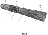
- the noncontact magnetic coupling of the microaxial pump as seen in figures 3 and 4 consists of an internal driven half coupling a hermetic cover separating the pump part from the power unit, and an external driving half coupling located in the power unit.
- the internal driven half coupling is made of permanent magnets 16 located on the end surface of the mount of second axial stage impeller 3 of the pump unit.
- the half couplings may be multi-pole with alternating poles.
- Permanent magnets 16 as seen in the sectional view B-B of figure 3 , are press fitted or glued to the mount of second axial stage impeller 3, and isolated by the hermetic cover, which, in its turn, is glued or soldered to the end surface of the mount of second axial stage impeller 3.
- the mount of second axial stage impeller 3 has at least four permanent magnets at equal angle increment from each other.
- the power unit is internal and placed inside the patient's body. This variant of implementation is shown in figure 1-4 . To separate the power unit from 'the blood zone' it is placed in a hermetic housing directly inside a large vessel (e.g. aorta) and includes motor 9 with a main shaft in the hermetic housing 2.
- a hermetic housing directly inside a large vessel (e.g. aorta) and includes motor 9 with a main shaft in the hermetic housing 2.
- the external driving half coupling in the form of bushing 14 with permanent magnets 16 is set directly on main shaft 9. Permanent magnets 16 are either press fitted or glued to the mount of bushing 14.
- the rotating main shaft of the motor 9 puts in motion the external driving half coupling set on the main shaft and transmits the rotation torque through hermetic housing 2 on to the driven half coupling comprising magnets in the mount of second axial stage impeller 3 via the permanent magnetic field.
- Cover 12 of the hermetic housing 2 of the power unit has a conical shape and an exit port. It is set on hermetic housing 12 usually by screwing.
- the power unit is external and placed outside the patient's body.
- the power unit is installed inside a housing 25 ( figure 5 ) outside the body. It comprises motor 9 with cover 24 and the main shaft.
- the main shaft is equipped with pulley 25 of the external driving half coupling of the power unit with permanent magnets 16.
- the torque from main shaft 9 is also transmitted to the external driving half coupling.
- the device has additional flexible transmitting broach 1 with terminal half couplings, one of which has a magnetic contact with the internal driven half coupling comprising magnets 16 in the mount of second axial stage impeller 3 in the pump unit, while another - with the external driving half coupling of the power unit consisting of pulley 26 with magnets 16.
- the terminal half couplings are press fitted/glued on a flexible shaft 22 that passes inside the hollow flexible broach 1 through the sleeve/roller bearings set at constant or variable intervals along the length of flexible transmitting shaft 22.
- flexible transmitting shaft 22 made in the form of a steel rod of round cross section.
- One of the terminal half couplings 18 is set in motion via a permanent magnetic field from the external magnetic half coupling consisting of pulley 26 and magnets 16 set on the main shaft of external motor 9 connected to the control board that regulates the modes of pump operation in the physiological (for the patient) discharge range.
- the control board may be installed on the patient or on a console next to the patient. Operation modes are selected depending on a personal requirement for oxygen. Thus, higher oxygen consumption requires faster motor rotation that provides higher discharge.
- Pulley 27 of terminal half coupling 18 with permanent magnets 16 is set on flexible transmitting shaft 22 by means of sleeve/roller bearing 15 inside housing 20 with cover 19 tightly connected to broach 1 by glue or soldering.
- housing 20 For sewing onto skin, housing 20 has eyes 21 ( figure 7 ) equally spaced around the circumference of housing 20.
- terminal half coupling 10 with permanent magnets 16 is press fitted/glued on flexible transmitting shaft 22 ( figure 6 ).
- Terminal half coupling 10 in the form of bushing is inside hermetic housing 23 with adaptor cover 28 connected to broach 1 and in contact with the internal driven half coupling formed by magnets 16 in the mount of second-stage impeller 3.
- terminal half coupling 18 located inside the patient's body via a permanent magnetic field. Then, the rotating torque from first terminal half coupling 18 passes on to connected flexible transmitting shaft 22 inside broach 1 placed inside a vessel up to the ascending aorta that contains the pump unit of the microaxial pump. At the end of flexible transmitting shaft 22 in hermetic housing 23 there is terminal half coupling 180 that transmits rotating torque through the wall of hermetic housing 23 on to the internal driven half coupling in the mount of second-stage impeller 3.
- the microaxial pump operates like this ( figure 8 ).
- the microaxial pump is placed in the cavity of the left ventricle by one of the known means:
- blood is taken from the cavity of the left or right ventricle by rotating impellers via a terminal broach. Passing through a flexible insert, blood gets to the inflow straightener, which thanks to vane positioning provides almost impactless flow onto the vanes of the first-stage impeller. In the zone of the first-stage impeller, the flow receives additional kinetic energy from rotation of the impeller and passes on to the vanes of the first-stage straightener that serve to reduce the whirl in the flow after the rotor and to increase head.
- the liquid flow gets to the zone of the second-stage impeller where it gets additional kinetic energy from shaft rotation and comes to the second-stage straightener with vanes that serve to reduce the whirl in the flow and to increase head.
- the flow is discharged into the cavity of ascending aorta and gets to the larger blood circle ensuring the physiologically necessary blood discharge and pressure difference.
- Rotation of impellers press fitted or glued on to the shaft is effected through the magnetic half coupling in the mount of the second-stage impeller.
- the mount of the second-stage impeller contains at least four permanent magnets.
- the rotating torque is transmitted via a permanent magnetic field from the second half coupling located inside a hermetic housing and installed either directly on the main shaft (with internal location of the motor), or press fitted/glued on the flexible shaft passing through the external flexible tube of the broach and sleeve/roller bearings set at intervals.
- the flexible shaft On the other side of the external flexible tube of the broach, the flexible shaft has an internal magnetic half coupling that is press fitted/ glued on it.
- the internal magnetic half coupling is set in motion by a permanent magnetic field from the external magnetic half coupling installed on the shaft of the external motor connected to the control board that selects operation modes.
- the use of the invention allows pumping blood without significantly impacting its temperature or shearing as the movable parts that come in contact with blood do not produce high gradients of shearing stress and the motor elements do not change the temperature in the areas of contact with the fluid.
Landscapes
- Health & Medical Sciences (AREA)
- Engineering & Computer Science (AREA)
- Heart & Thoracic Surgery (AREA)
- Cardiology (AREA)
- Biomedical Technology (AREA)
- Anesthesiology (AREA)
- Mechanical Engineering (AREA)
- Hematology (AREA)
- Life Sciences & Earth Sciences (AREA)
- Animal Behavior & Ethology (AREA)
- General Health & Medical Sciences (AREA)
- Public Health (AREA)
- Veterinary Medicine (AREA)
- Vascular Medicine (AREA)
- External Artificial Organs (AREA)
Applications Claiming Priority (2)
| Application Number | Priority Date | Filing Date | Title |
|---|---|---|---|
| RU2016144052A RU2637605C1 (ru) | 2016-11-09 | 2016-11-09 | Микроаксиальный насос поддержки кровообращения (варианты) |
| PCT/RU2017/000840 WO2018088939A1 (ru) | 2016-11-09 | 2017-11-09 | Микроаксиальный насос поддержки кровообращения (варианты) |
Publications (2)
| Publication Number | Publication Date |
|---|---|
| EP3539584A1 true EP3539584A1 (de) | 2019-09-18 |
| EP3539584A4 EP3539584A4 (de) | 2020-06-03 |
Family
ID=60581432
Family Applications (1)
| Application Number | Title | Priority Date | Filing Date |
|---|---|---|---|
| EP17870134.8A Withdrawn EP3539584A4 (de) | 2016-11-09 | 2017-11-09 | Mikroaxialpumpe zur unterstützung der blutzirkulation (varianten) |
Country Status (3)
| Country | Link |
|---|---|
| EP (1) | EP3539584A4 (de) |
| RU (1) | RU2637605C1 (de) |
| WO (1) | WO2018088939A1 (de) |
Cited By (11)
| Publication number | Priority date | Publication date | Assignee | Title |
|---|---|---|---|---|
| WO2021062566A1 (en) * | 2019-10-05 | 2021-04-08 | Puzzle Medical Devices Inc. | Modular impeller system for fluid circulation |
| WO2021062565A3 (en) * | 2019-10-04 | 2021-05-14 | Puzzle Medical Devices Inc. | Fluid kinetic energy redistribution system for use as hemodynamic support |
| CN114177516A (zh) * | 2021-12-22 | 2022-03-15 | 江苏大学 | 一种用于左心室辅助的大流量两级导管泵及其使用方法 |
| CN114602055A (zh) * | 2022-03-07 | 2022-06-10 | 江苏大学镇江流体工程装备技术研究院 | 一种急救型快速微创植入的多级导管血泵 |
| WO2023284339A1 (zh) * | 2021-07-12 | 2023-01-19 | 苏州心擎医疗技术有限公司 | 用于对心脏在发生功能衰竭时进行辅助的装置 |
| WO2023098470A1 (zh) * | 2021-12-03 | 2023-06-08 | 深圳核心医疗科技有限公司 | 血泵及其驱动装置 |
| US11690997B2 (en) | 2018-04-06 | 2023-07-04 | Puzzle Medical Devices Inc. | Mammalian body conduit intralumenal device and lumen wall anchor assembly, components thereof and methods of implantation and explanation thereof |
| US12053623B2 (en) | 2019-03-26 | 2024-08-06 | Puzzle Medical Devices Inc. | Modular mammalian body implantable fluid flow influencing device and related methods |
| US12161853B2 (en) | 2022-11-01 | 2024-12-10 | Puzzle Medical Devices Inc. | Implantable medical devices and related methods thereof |
| WO2025090558A1 (en) * | 2023-10-23 | 2025-05-01 | Boston Scientific Scimed, Inc. | Percutaneous blood pump with motor connection |
| US12383723B2 (en) | 2019-10-05 | 2025-08-12 | Puzzle Medical Devices Inc. | Mammalian body implantable fluid flow influencing device |
Families Citing this family (39)
| Publication number | Priority date | Publication date | Assignee | Title |
|---|---|---|---|---|
| EP4732889A2 (de) | 2017-06-07 | 2026-04-29 | Supira Medical, Inc. | Vorrichtungen, systeme und verfahren zur bewegung intravaskulärer flüssigkeiten |
| US11511103B2 (en) | 2017-11-13 | 2022-11-29 | Shifamed Holdings, Llc | Intravascular fluid movement devices, systems, and methods of use |
| DE102018201030B4 (de) | 2018-01-24 | 2025-10-16 | Kardion Gmbh | Magnetkuppelelement mit magnetischer Lagerungsfunktion |
| JP7410034B2 (ja) | 2018-02-01 | 2024-01-09 | シファメド・ホールディングス・エルエルシー | 血管内血液ポンプならびに使用および製造の方法 |
| DE102018207594A1 (de) | 2018-05-16 | 2019-11-21 | Kardion Gmbh | Rotor, Magnetkupplungsvorrichtung, Elektromotor für ein Herzunterstützungssystem, Pumpeneinheit für ein Herzunterstützungssystem sowie Verfahren zum Herstellen eines Rotors |
| DE102018207611A1 (de) | 2018-05-16 | 2019-11-21 | Kardion Gmbh | Rotorlagerungssystem |
| DE102018207575A1 (de) | 2018-05-16 | 2019-11-21 | Kardion Gmbh | Magnetische Stirndreh-Kupplung zur Übertragung von Drehmomenten |
| DE102018208541A1 (de) | 2018-05-30 | 2019-12-05 | Kardion Gmbh | Axialpumpe für ein Herzunterstützungssystem und Verfahren zum Herstellen einer Axialpumpe für ein Herzunterstützungssystem |
| DE102018208549A1 (de) | 2018-05-30 | 2019-12-05 | Kardion Gmbh | Elektronikmodul für ein Herzunterstützungssystem und Verfahren zum Herstellen eines Elektronikmoduls für ein Herzunterstützungssystem |
| DE102018208550A1 (de) | 2018-05-30 | 2019-12-05 | Kardion Gmbh | Leitungsvorrichtung zum Leiten eines Blutstroms für ein Herzunterstützungssystem, Herzunterstützungssystem und Verfahren zum Herstellen einer Leitungsvorrichtung |
| DE102018208539A1 (de) | 2018-05-30 | 2019-12-05 | Kardion Gmbh | Motorgehäusemodul zum Abdichten eines Motorraums eines Motors eines Herzunterstützungssystems und Herzunterstützungssystem und Verfahren zum Montieren eines Herzunterstützungssystems |
| DE102018208538A1 (de) | 2018-05-30 | 2019-12-05 | Kardion Gmbh | Intravasale Blutpumpe und Verfahren zur Herstellung von elektrischen Leiterbahnen |
| DE102018210058A1 (de) | 2018-06-21 | 2019-12-24 | Kardion Gmbh | Statorschaufelvorrichtung zur Strömungsführung eines aus einer Austrittsöffnung eines Herzunterstützungssystems ausströmenden Fluids, Herzunterstützungssystem mit Statorschaufelvorrichtung, Verfahren zum Betreiben einer Statorschaufelvorrichtung und Herstellverfahren |
| DE102018210076A1 (de) | 2018-06-21 | 2019-12-24 | Kardion Gmbh | Verfahren und Vorrichtung zum Erkennen eines Verschleißzustands eines Herzunterstützungssystems, Verfahren und Vorrichtung zum Betreiben eines Herzunterstützungssystems und Herzunterstützungssystem |
| DE102018211297A1 (de) | 2018-07-09 | 2020-01-09 | Kardion Gmbh | Herzunterstützungssystem und Verfahren zur Überwachung der Integrität einer Haltestruktur eines Herzunterstützungssystems |
| DE102018211327A1 (de) | 2018-07-10 | 2020-01-16 | Kardion Gmbh | Laufrad für ein implantierbares, vaskuläres Unterstützungssystem |
| DE102018211328A1 (de) | 2018-07-10 | 2020-01-16 | Kardion Gmbh | Laufradgehäuse für ein implantierbares, vaskuläres Unterstützungssystem |
| DE102018212153A1 (de) | 2018-07-20 | 2020-01-23 | Kardion Gmbh | Zulaufleitung für eine Pumpeneinheit eines Herzunterstützungssystems, Herzunterstützungssystem und Verfahren zum Herstellen einer Zulaufleitung für eine Pumpeneinheit eines Herzunterstützungssystems |
| WO2020028537A1 (en) | 2018-07-31 | 2020-02-06 | Shifamed Holdings, Llc | Intravascaular blood pumps and methods of use |
| AU2019320533B2 (en) | 2018-08-07 | 2024-11-21 | Kardion Gmbh | Bearing device for a cardiac support system, and method for flushing an intermediate space in a bearing device for a cardiac support system |
| WO2020073047A1 (en) | 2018-10-05 | 2020-04-09 | Shifamed Holdings, Llc | Intravascular blood pumps and methods of use |
| WO2021011473A1 (en) | 2019-07-12 | 2021-01-21 | Shifamed Holdings, Llc | Intravascular blood pumps and methods of manufacture and use |
| US11654275B2 (en) | 2019-07-22 | 2023-05-23 | Shifamed Holdings, Llc | Intravascular blood pumps with struts and methods of use and manufacture |
| EP4010046A4 (de) | 2019-08-07 | 2023-08-30 | Calomeni, Michael | Katheterblutpumpen und zusammenklappbare pumpengehäuse |
| EP4034192B1 (de) | 2019-09-25 | 2025-12-24 | Supira Medical, Inc. | Intravaskuläre blutpumpensysteme und verfahren zur verwendung und steuerung davon |
| WO2021062260A1 (en) | 2019-09-25 | 2021-04-01 | Shifamed Holdings, Llc | Catheter blood pumps and collapsible blood conduits |
| EP4034221B1 (de) | 2019-09-25 | 2024-11-13 | Shifamed Holdings, LLC | Katheterblutpumpen und zusammenklappbare pumpengehäuse |
| RU2731806C1 (ru) * | 2019-12-10 | 2020-09-08 | Федеральное государственное автономное образовательное учреждение высшего образования "Национальный исследовательский университет "Московский институт электронной техники" | Осевой насос для перекачивания крови |
| EP4072650A4 (de) | 2019-12-11 | 2024-01-10 | Shifamed Holdings, LLC | Absteigende aorten- und hohlvenenblutpumpen |
| US12599758B2 (en) | 2019-12-19 | 2026-04-14 | Shifamed Holdings, Llc | Intravascular blood pumps, motors, and fluid control |
| DE102020102474A1 (de) | 2020-01-31 | 2021-08-05 | Kardion Gmbh | Pumpe zum Fördern eines Fluids und Verfahren zum Herstellen einer Pumpe |
| RU2759127C2 (ru) * | 2020-04-14 | 2021-11-09 | Общество с ограниченной ответственностью "ХАРТ МЕХАНИКА" | Катетерный микронасос для механической поддержки кровообращения |
| WO2021243263A1 (en) | 2020-05-29 | 2021-12-02 | Shifamed Holdings, Llc | Intravascular blood pumps |
| RU2744482C1 (ru) * | 2020-06-17 | 2021-03-10 | Евгений Петрович Банин | Насос вспомогательного кровообращения с торцевым двигателем |
| CA3192451A1 (en) | 2020-09-14 | 2022-03-17 | Johannes Bette | Cardiovascular support pump having an impeller with a variable flow area |
| JP2023550938A (ja) | 2020-11-20 | 2023-12-06 | カルディオン ゲーエムベーハー | ガイドワイヤ補助具付き機械的循環支持システム |
| WO2023070515A1 (zh) * | 2021-10-29 | 2023-05-04 | 苏州心擎医疗技术有限公司 | 导管泵 |
| CN116603163B (zh) * | 2022-01-26 | 2024-10-11 | 心擎医疗(苏州)股份有限公司 | 用于对心脏在发生功能衰竭时进行辅助的装置 |
| CN116440404B (zh) * | 2023-05-18 | 2024-03-08 | 苏州心岭迈德医疗科技有限公司 | 一种基于磁力驱动的封闭式微型泵 |
Family Cites Families (19)
| Publication number | Priority date | Publication date | Assignee | Title |
|---|---|---|---|---|
| US5211546A (en) * | 1990-05-29 | 1993-05-18 | Nu-Tech Industries, Inc. | Axial flow blood pump with hydrodynamically suspended rotor |
| RU2051695C1 (ru) | 1991-02-20 | 1996-01-10 | Научно-Исследовательский Институт Трансплантологии И Искусственных Органов | Осевой лопаточный насос для вспомогательного кровообращения |
| DE69331271T2 (de) * | 1992-07-30 | 2002-12-12 | Cobe Cardiovascular Inc | Kreiselblutpumpe |
| RU2131271C1 (ru) | 1993-10-25 | 1999-06-10 | Научно-исследовательский институт трансплантологии и искусственных органов МЗ РФ | Осевой лопаточный насос для вспомогательного кровообращения |
| US5507629A (en) | 1994-06-17 | 1996-04-16 | Jarvik; Robert | Artificial hearts with permanent magnet bearings |
| US6176822B1 (en) | 1998-03-31 | 2001-01-23 | Impella Cardiotechnik Gmbh | Intracardiac blood pump |
| WO2000019097A1 (en) * | 1998-09-30 | 2000-04-06 | A-Med Systems, Inc. | Blood pump system with magnetic cable drive |
| US6217541B1 (en) * | 1999-01-19 | 2001-04-17 | Kriton Medical, Inc. | Blood pump using cross-flow principles |
| CA2369955C (en) * | 1999-04-20 | 2005-10-18 | Berlin Heart Ag | Device for delivering single-phase or multiphase fluids without altering the properties thereof |
| WO2001017581A2 (en) | 1999-09-03 | 2001-03-15 | A-Med Systems, Inc. | Guidable intravascular blood pump and related methods |
| AU2003273612A1 (en) * | 2002-06-11 | 2003-12-22 | Walid Aboul-Hosn | Percutaneously introduced blood pump and related methods |
| US8419609B2 (en) * | 2005-10-05 | 2013-04-16 | Heartware Inc. | Impeller for a rotary ventricular assist device |
| EP1898971B1 (de) * | 2005-06-06 | 2015-03-11 | The Cleveland Clinic Foundation | Blutpumpe |
| US20090112312A1 (en) | 2007-02-26 | 2009-04-30 | Larose Jeffrey A | Intravascular ventricular assist device |
| AT504990B1 (de) * | 2007-02-27 | 2008-12-15 | Miracor Medizintechnik Handels | Katheter zur unterstützung der leistung eines herzens |
| US8489190B2 (en) * | 2007-10-08 | 2013-07-16 | Ais Gmbh Aachen Innovative Solutions | Catheter device |
| EP2248544A1 (de) * | 2009-05-05 | 2010-11-10 | ECP Entwicklungsgesellschaft mbH | Im Durchmesser veränderbare Fluidpumpe, insbesondere für die medizinische Verwendung |
| US8849398B2 (en) * | 2011-08-29 | 2014-09-30 | Minnetronix, Inc. | Expandable blood pump for cardiac support |
| US20130138205A1 (en) * | 2011-11-28 | 2013-05-30 | MI-VAD, Inc. | Ventricular assist device and method |
-
2016
- 2016-11-09 RU RU2016144052A patent/RU2637605C1/ru active
-
2017
- 2017-11-09 WO PCT/RU2017/000840 patent/WO2018088939A1/ru not_active Ceased
- 2017-11-09 EP EP17870134.8A patent/EP3539584A4/de not_active Withdrawn
Cited By (14)
| Publication number | Priority date | Publication date | Assignee | Title |
|---|---|---|---|---|
| US11690997B2 (en) | 2018-04-06 | 2023-07-04 | Puzzle Medical Devices Inc. | Mammalian body conduit intralumenal device and lumen wall anchor assembly, components thereof and methods of implantation and explanation thereof |
| US12053623B2 (en) | 2019-03-26 | 2024-08-06 | Puzzle Medical Devices Inc. | Modular mammalian body implantable fluid flow influencing device and related methods |
| WO2021062565A3 (en) * | 2019-10-04 | 2021-05-14 | Puzzle Medical Devices Inc. | Fluid kinetic energy redistribution system for use as hemodynamic support |
| US12383723B2 (en) | 2019-10-05 | 2025-08-12 | Puzzle Medical Devices Inc. | Mammalian body implantable fluid flow influencing device |
| WO2021062566A1 (en) * | 2019-10-05 | 2021-04-08 | Puzzle Medical Devices Inc. | Modular impeller system for fluid circulation |
| WO2023284339A1 (zh) * | 2021-07-12 | 2023-01-19 | 苏州心擎医疗技术有限公司 | 用于对心脏在发生功能衰竭时进行辅助的装置 |
| WO2023098470A1 (zh) * | 2021-12-03 | 2023-06-08 | 深圳核心医疗科技有限公司 | 血泵及其驱动装置 |
| US12582814B2 (en) | 2021-12-03 | 2026-03-24 | Shenzhen Core Medical Technology Co., Ltd. | Blood pump and driving device thereof |
| CN114177516A (zh) * | 2021-12-22 | 2022-03-15 | 江苏大学 | 一种用于左心室辅助的大流量两级导管泵及其使用方法 |
| CN114177516B (zh) * | 2021-12-22 | 2024-05-14 | 江苏大学 | 一种用于左心室辅助的大流量两级导管泵及其使用方法 |
| CN114602055A (zh) * | 2022-03-07 | 2022-06-10 | 江苏大学镇江流体工程装备技术研究院 | 一种急救型快速微创植入的多级导管血泵 |
| CN114602055B (zh) * | 2022-03-07 | 2025-09-05 | 江苏大学镇江流体工程装备技术研究院 | 一种急救型快速微创植入的多级导管血泵 |
| US12161853B2 (en) | 2022-11-01 | 2024-12-10 | Puzzle Medical Devices Inc. | Implantable medical devices and related methods thereof |
| WO2025090558A1 (en) * | 2023-10-23 | 2025-05-01 | Boston Scientific Scimed, Inc. | Percutaneous blood pump with motor connection |
Also Published As
| Publication number | Publication date |
|---|---|
| WO2018088939A1 (ru) | 2018-05-17 |
| RU2637605C1 (ru) | 2017-12-05 |
| EP3539584A4 (de) | 2020-06-03 |
Similar Documents
| Publication | Publication Date | Title |
|---|---|---|
| EP3539584A1 (de) | Mikroaxialpumpe zur unterstützung der blutzirkulation (varianten) | |
| US11185678B2 (en) | Blood pump | |
| US10646630B2 (en) | Cantilevered rotor pump and methods for axial flow blood pumping | |
| US9895476B2 (en) | Intravascular ventricular assist device | |
| EP2167158B1 (de) | Axiale rotationspumpe mit verringertem durchmesser zur herzunterstützung | |
| US7972122B2 (en) | Multiple rotor, wide blade, axial flow pump | |
| JP4889492B2 (ja) | インペラ | |
| JP6009421B2 (ja) | 遠心回転血液ポンプ | |
| US9162018B2 (en) | Cardiac pump | |
| EP3668558A1 (de) | Pumpe-zu-motor-verbindungssystem |
Legal Events
| Date | Code | Title | Description |
|---|---|---|---|
| STAA | Information on the status of an ep patent application or granted ep patent |
Free format text: STATUS: THE INTERNATIONAL PUBLICATION HAS BEEN MADE |
|
| PUAI | Public reference made under article 153(3) epc to a published international application that has entered the european phase |
Free format text: ORIGINAL CODE: 0009012 |
|
| STAA | Information on the status of an ep patent application or granted ep patent |
Free format text: STATUS: REQUEST FOR EXAMINATION WAS MADE |
|
| 17P | Request for examination filed |
Effective date: 20190606 |
|
| AK | Designated contracting states |
Kind code of ref document: A1 Designated state(s): AL AT BE BG CH CY CZ DE DK EE ES FI FR GB GR HR HU IE IS IT LI LT LU LV MC MK MT NL NO PL PT RO RS SE SI SK SM TR |
|
| AX | Request for extension of the european patent |
Extension state: BA ME |
|
| DAV | Request for validation of the european patent (deleted) | ||
| DAX | Request for extension of the european patent (deleted) | ||
| A4 | Supplementary search report drawn up and despatched |
Effective date: 20200508 |
|
| RIC1 | Information provided on ipc code assigned before grant |
Ipc: A61M 1/12 20060101ALI20200501BHEP Ipc: F04D 3/02 20060101ALI20200501BHEP Ipc: A61M 1/10 20060101AFI20200501BHEP |
|
| STAA | Information on the status of an ep patent application or granted ep patent |
Free format text: STATUS: EXAMINATION IS IN PROGRESS |
|
| 17Q | First examination report despatched |
Effective date: 20230504 |
|
| REG | Reference to a national code |
Ref country code: DE Ref legal event code: R079 Free format text: PREVIOUS MAIN CLASS: A61M0001100000 Ipc: A61M0060130000 |
|
| GRAP | Despatch of communication of intention to grant a patent |
Free format text: ORIGINAL CODE: EPIDOSNIGR1 |
|
| STAA | Information on the status of an ep patent application or granted ep patent |
Free format text: STATUS: GRANT OF PATENT IS INTENDED |
|
| RIC1 | Information provided on ipc code assigned before grant |
Ipc: A61M 60/825 20210101ALI20240506BHEP Ipc: A61M 60/81 20210101ALI20240506BHEP Ipc: A61M 60/806 20210101ALI20240506BHEP Ipc: A61M 60/422 20210101ALI20240506BHEP Ipc: A61M 60/419 20210101ALI20240506BHEP Ipc: A61M 60/414 20210101ALI20240506BHEP Ipc: A61M 60/237 20210101ALI20240506BHEP Ipc: A61M 60/13 20210101AFI20240506BHEP |
|
| INTG | Intention to grant announced |
Effective date: 20240531 |
|
| STAA | Information on the status of an ep patent application or granted ep patent |
Free format text: STATUS: THE APPLICATION IS DEEMED TO BE WITHDRAWN |
|
| 18D | Application deemed to be withdrawn |
Effective date: 20241001 |