EP3539604B1 - Appareil oxythérapeutique - Google Patents
Appareil oxythérapeutique Download PDFInfo
- Publication number
- EP3539604B1 EP3539604B1 EP19160749.8A EP19160749A EP3539604B1 EP 3539604 B1 EP3539604 B1 EP 3539604B1 EP 19160749 A EP19160749 A EP 19160749A EP 3539604 B1 EP3539604 B1 EP 3539604B1
- Authority
- EP
- European Patent Office
- Prior art keywords
- gas
- patient
- nasal
- oxytherapy
- pressure
- Prior art date
- Legal status (The legal status is an assumption and is not a legal conclusion. Google has not performed a legal analysis and makes no representation as to the accuracy of the status listed.)
- Active
Links
Images


Classifications
-
- A—HUMAN NECESSITIES
- A61—MEDICAL OR VETERINARY SCIENCE; HYGIENE
- A61M—DEVICES FOR INTRODUCING MEDIA INTO, OR ONTO, THE BODY; DEVICES FOR TRANSDUCING BODY MEDIA OR FOR TAKING MEDIA FROM THE BODY; DEVICES FOR PRODUCING OR ENDING SLEEP OR STUPOR
- A61M16/00—Devices for influencing the respiratory system of patients by gas treatment, e.g. ventilators; Tracheal tubes
- A61M16/06—Respiratory or anaesthetic masks
- A61M16/0666—Nasal cannulas or tubing
- A61M16/0672—Nasal cannula assemblies for oxygen therapy
-
- A—HUMAN NECESSITIES
- A61—MEDICAL OR VETERINARY SCIENCE; HYGIENE
- A61M—DEVICES FOR INTRODUCING MEDIA INTO, OR ONTO, THE BODY; DEVICES FOR TRANSDUCING BODY MEDIA OR FOR TAKING MEDIA FROM THE BODY; DEVICES FOR PRODUCING OR ENDING SLEEP OR STUPOR
- A61M16/00—Devices for influencing the respiratory system of patients by gas treatment, e.g. ventilators; Tracheal tubes
- A61M16/20—Valves specially adapted to medical respiratory devices
- A61M16/208—Non-controlled one-way valves, e.g. exhalation, check, pop-off non-rebreathing valves
-
- A—HUMAN NECESSITIES
- A61—MEDICAL OR VETERINARY SCIENCE; HYGIENE
- A61M—DEVICES FOR INTRODUCING MEDIA INTO, OR ONTO, THE BODY; DEVICES FOR TRANSDUCING BODY MEDIA OR FOR TAKING MEDIA FROM THE BODY; DEVICES FOR PRODUCING OR ENDING SLEEP OR STUPOR
- A61M16/00—Devices for influencing the respiratory system of patients by gas treatment, e.g. ventilators; Tracheal tubes
- A61M16/20—Valves specially adapted to medical respiratory devices
- A61M16/208—Non-controlled one-way valves, e.g. exhalation, check, pop-off non-rebreathing valves
- A61M16/209—Relief valves
-
- A—HUMAN NECESSITIES
- A61—MEDICAL OR VETERINARY SCIENCE; HYGIENE
- A61M—DEVICES FOR INTRODUCING MEDIA INTO, OR ONTO, THE BODY; DEVICES FOR TRANSDUCING BODY MEDIA OR FOR TAKING MEDIA FROM THE BODY; DEVICES FOR PRODUCING OR ENDING SLEEP OR STUPOR
- A61M16/00—Devices for influencing the respiratory system of patients by gas treatment, e.g. ventilators; Tracheal tubes
- A61M16/06—Respiratory or anaesthetic masks
- A61M16/0683—Holding devices therefor
- A61M16/0688—Holding devices therefor by means of an adhesive
-
- A—HUMAN NECESSITIES
- A61—MEDICAL OR VETERINARY SCIENCE; HYGIENE
- A61M—DEVICES FOR INTRODUCING MEDIA INTO, OR ONTO, THE BODY; DEVICES FOR TRANSDUCING BODY MEDIA OR FOR TAKING MEDIA FROM THE BODY; DEVICES FOR PRODUCING OR ENDING SLEEP OR STUPOR
- A61M2202/00—Special media to be introduced, removed or treated
- A61M2202/02—Gases
- A61M2202/0208—Oxygen
Definitions
- the invention relates to an oxygen therapy device for use in so-called high-flow oxygen therapy.
- High-flow oxygen therapy also known as high-flow nasal cannula (HFNC)
- HFOT high-flow nasal cannula
- patient gas an oxygen-gas mixture
- glasses or Mask an oxygen-gas mixture in a flow range of 2 - 60 l / min is supplied to the patient, which thus exceeds the inspiratory flow.
- This mixture is warmed up and moistened beforehand using an active humidifier.
- This form of ventilation is mainly used in neonatology and pediatrics, but is increasingly being used in all age groups.
- Such a high-flow oxygen therapy system is known in which a nozzle is additionally provided, by means of which ambient air is mixed with the patient gas.
- the EP 2 414 019 B1 and the EP 2 068 992 B1 each describe a high-flow system that has a control unit and a breathing sensor arranged in the gas distributor of the mask, the control unit controlling the gas flow based on the values determined with the breathing sensor synchronously with the patient's spontaneous breathing.
- WO 2016/157105 A1 discloses a ventilator comprising a nasal part, a molded tube connected thereto, and a valve.
- the ventilator is designed to deliver breathing gas to the patient in two configurations: at high pressure and at lower pressure, with switching between the two configurations by means of a valve that causes an artificial leak in the molded hose to reduce pressure.
- various configurations of a pressure relief valve are shown.
- a pressure relief valve with a connected alarm whistle which can be inserted into a ventilation hose via an adapter, is used in US 2010/0282253 A1 disclosed.
- This pressure relief valve is realized with a spiral spring. Since several components are movably arranged with respect to one another, this pressure relief valve has a comparatively complex structure, with the possibility of the moving components getting stuck or jamming - and thus failure of the pressure relief valve - cannot be ruled out. Finally, an additional "predetermined breaking point" is built into the ventilation circuit through the adapter.
- FIG. 11 shows a mask for ventilating a patient comprising a nose piece and a mouthpiece. Each part has its own gas connection. Both parts are detachably connected to one another, with a valve attached in the fluidic transition between the nose part and the mouthpiece enabling two separate ventilation circuits.
- WO 2015/192186 US 2011/0067704 , WO2013 / 148901 , US 2014/0150789 disclose nasal cannulas with pressure regulating valves.
- the invention is based on the object of avoiding the above-mentioned disadvantages, such as an uncontrolled excessive tracheal pressure and the required accuracy and experience when putting on the oxygen therapy system, with an oxygen therapy device that is easy to use is to be provided to offer the patient a high level of security with regard to the gas pressure provided and a high level of reliability with regard to the gas supply.
- an oxygen therapy device for high-flow oxygen therapy with patient gas for ventilation support for a patient, which has an integrated, positively controlled pressure control device without electronic components, with specially designed molded hoses also ensuring an uninterrupted supply of patient gas to the patient.
- the oxygen therapy device comprises a nose part for attachment to the patient, a gas distribution device, at least one molded hose and at least one mechanical pressure control valve.
- the nasal part (also known as a nasal prong in medical terminology) introduces the patient's gas into the patient's nose. It contains a gas channel for the patient gas and two nasal cannulas that are in fluid connection with the gas channel, each with a patient gas outlet opening.
- the nose part comprises at least one gas inlet opening for supplying patient gas into the gas channel.
- the nose part also has two wing-like adhesive elements with adhesive silicone gel, hereinafter referred to as adhesive film.
- adhesive film two nasal cannulas are inserted nasally and attached above the upper lip with an adhesive film on each side of the face. This prevents the nasal cannulas from slipping out.
- the nose part By having the nose part slightly curved following the anatomy of the face or, e.g. B. is made angled between the two nasal cannulas, the tensile force on the adhesive elements is reduced, which also the load on the skin is decreased.
- the nose part also has a slight taper in the middle to prevent it from kinking.
- the nose part comprises only one gas inlet opening for supplying patient gas, a patient gas supply device, for example in the form of a tubular element, being connectable in its first end area to the molded tube.
- the patient gas supply device has at least one adhesive film, by means of which it is positioned on the patient's forehead.
- the two nasal cannulas which are arranged at the second end region of the patient gas supply device, can be detachably connected to the same.
- a patient gas supply device of a uniform size can advantageously be used, with only the nasal cannulas having to be exchanged in a patient-specific manner. So it is possible that different sizes can be adapted to patient types just by exchanging the nose part.
- the nose part prefferably designed as an individual part so that it can be adapted, plugged, clipped or pushed onto the gas distribution device.
- the patient gas supply device is designed as a central supply above the bridge of the nose, with a cross-section similar to that of the supply line (hose system). In this way, a strong pressure loss in the system can be prevented right down to the nasal cannulas, the diameter of which is reduced compared to the diameter of the gas channel of the nasal part.
- the nose part according to this variant can be designed in the nose area in such a way that the shape of the nose contour is modeled, so that the nose part hugs the nose. This area can also be made a little softer. As a result, the overall system is guided significantly better, so that incorrect positioning or slipping can be prevented, and also because of the soft Irritation or damage to the patient's nose area is avoided.
- Both variants have nasal cannulas which are angled towards the patient in such a way that they adapt to the nasal vestibule, thereby avoiding damage to or irritation of the nasal wall.
- the nasal cannulas have a bevel or bevel at their end area with the patient gas outlet opening so that, on the one hand, the cannulas do not press against the inner wall of the nose and, on the other hand, the gas flow into the nose is little impaired.
- the gas distribution device is used to connect the oxygen therapy device to a patient gas source.
- the gas distribution device has an adapter connection for a basically known gas supply hose from a patient gas source.
- the gas distribution device has one or two connection sockets, into each of which a molded tube of the oxygen therapy device can be inserted. Each connection socket thus defines a gas outlet opening of the gas distribution device.
- connection sockets have a locking device on the inside and spaced apart from the molded hose insertion opening, e.g. B. in the form of a circumferential bead or a shoulder, so that the molded hose can only be pushed into the connection socket of the gas distribution device as far as the locking device.
- the internal cross-section of the connection socket essentially corresponds in shape and dimensions to the external cross-sectional shape of the molded hose.
- the molded hose has a gas inlet opening and a gas outlet opening, the molded hose opening with its gas outlet opening into a gas inlet opening of the nose part.
- the end area of the molded hose opposite this end area namely the end area with the gas inlet opening, is or will be inserted into a connection socket of the gas distribution device and is thus connected to a gas outlet opening of the gas distribution device.
- the molded hose can additionally each with an adhesive, for. B. a silicone adhesive, be fixed.
- the molded hose is designed in a basically known manner in the shape of a cylinder or tube.
- the molded tube can have a round or elliptical external geometry.
- the geometric shape of the cross-section of the inner wall, i.e. H. the (inner) cross-sectional shape of the gas channel in the molded hose differs according to the invention from the shape of an ellipse, in particular also from the shape of a circle.
- the molded hose has a cross-sectional shape of its gas channel that is star, flower, sector of a circle or polygonal shape.
- two or more gas ducts are formed in the longitudinal direction of the molded hose, which gas ducts run essentially parallel to one another.
- the molded hose can have four gas channels, each of which has a cross-sectional shape in the shape of a sector of a circle.
- the gas channels can run strictly separated from one another along the entire length of the molded hose, but they can also have fluidic connections to one another at one or more positions.
- the pressure regulating valve comprises at least one valve flap, the mode of operation of which is purely mechanical, ie it has no electrical components.
- the pressure control valve is set up to compensate for both a negative pressure difference between the patient gas pressure in the oxygen therapy device and atmospheric pressure and a positive pressure difference with respect to atmospheric pressure.
- the pressure regulating valve or the at least one valve flap is designed to open above a predetermined amount of the pressure difference, the degree of opening of the valve flap being proportional to the pressure difference.
- the at least one pressure control valve is preferably an integral part of the nose part or the gas distribution device, the pressure control valve being designed monolithically with the nose part or the gas distribution device.
- the pressure regulating valve integrated in the oxygen therapy device thus advantageously protects the patient. Because the interaction of the adjusted gas flow, the nasal cannulas and the shape of the patient's nose, various factors such as B. affects the leakage at the junction cannula - nose. As a result, depending on the situation, different pressures can be present in the patient's airways. If the pressure is too high, the valve flaps open and protect the patient from too high a tracheal pressure, so that a barotrauma or a pneumothorax is reliably avoided.
- the pressure regulating valve can be designed in the form of a cylinder or a cuboid through which the patient gas flows, with the gas flow direction preferably running transversely to the cylinder longitudinal axis in the case of a cylinder.
- At least one side wall of the cuboid or a top surface of the cylinder can be a silicone membrane into which, according to the invention, at least two intersecting slots are introduced.
- at least four movable valve flaps are formed which - subject to a spring force inherent in the material - can move freely outwards and inwards.
- the contours allow a defined opening behavior of the valve flaps depending on the pressure difference between the internal system pressure and the atmospheric pressure. If there is a pressure difference between the gas duct and the outside atmosphere, pressure compensation can thus take place.
- a protective cap can be attached to the outside of the pressure control valve above the silicone membrane.
- This protective cap can partially or completely cover the valve flaps, in which case gas exchange is still possible, for example through slots made laterally in the protective cap.
- the protective cap partially or completely encloses the entire pressure control valve. Since it is provided in particular that the pressure control valve is monolithically integrated into the corresponding component of the oxygen therapy device, namely the nose part or the gas distribution device is integrated, it can also be provided that said component consists entirely of the material of the pressure control valve or the valve flaps.
- the protective cap which can be made of a different material, thus offers additional stabilization of the soft silicone valve housing.
- the invention can further be designed in such a way that the gas distribution device has one or two pressure regulating valves.
- the gas distribution device preferably comprises two pressure regulating valves which - opposite one another - are arranged between the adapter connection and the one or two connection sockets.
- the nasal part has one or two pressure regulating valves, which are preferably arranged in the gas channel between the gas inlet opening of the nasal part and the nasal cannula.
- the pressure regulating valve in the nasal part advantageously enables, in addition to protecting against excessive patient pressure, unimpeded spontaneous breathing by the patient so that he does not have to breathe against the resistance of the entire breathing system or hose system.
- At least one pressure control valve is integrated in the forehead adhesive pad or can be attached there.
- the nasal cannulas have a leakage device at their patient gas outlet opening, i. That is, there is no gas-tight connection between the patient's nose and the nasal part.
- This nasal part variant with defined leakage at the nasal cannula is used to determine the patient pressure more precisely. Due to the known leakage and the gas flow and pressure emitted by the device, the patient pressure can thus be approximately determined, for example by means of a measuring and control component.
- the patient pressure can also be approximately determined by the combination of the valve and the defined leakage via the pressure curve of the valve.
- the leakage device can be designed in the form of a ring or hollow cylinder which is arranged concentrically to the longitudinal axis of the nasal cannula and which is attached to the outside of the wall of the nasal cannula in the area of the patient gas outlet opening by means of spacers.
- the oxygen therapy device comprises only one molded tube.
- this molded tube is placed over the patient's head, running above the bridge of the nose.
- the oxygen therapy device comprises two shaped hoses, each of which is led from the gas distribution device to a gas inlet opening of the nose part.
- the two shaped hoses are placed over the ears when the oxygen therapy device is put on (similar to the temple of glasses).
- the oxygen therapy device also has a hose guide, by means of which the two shaped hoses are fixed to one another.
- the hose guide is designed to be displaceable along (the longitudinal axes) of the molded hoses.
- the inner cross-section in the molded hose is rotated about the molded hose longitudinal axis, so that the gas channel is helical.
- these can each be rotated about their own longitudinal axis of the gas duct.
- the gas channels can be guided around one another in the sense of a multiple helix along the longitudinal axis of the molded hose, i. H. wrapped, be.
- an open-pored foam can be introduced into the molded hose, which completely fills the gas channel.
- the open-pored foam allows an undisturbed gas flow, whereby a compression or kinking of the molded hose, and thus an interruption of the gas flow is reliably prevented, so that the patient is always supplied with patient gas.
- the Figure 1 shows the oxygen therapy device with the nasal part 1, two shaped hoses 5 and the gas distribution device 3.
- the nasal part 1 comprises the two nasal cannulas 7 and the adhesive films 6 for fixing the nasal part on the patient's skin.
- the two molded hoses 5 are held together by the displaceable hose guide 2.
- the nose part 1 according to Figure 2 comprises the two pressure regulating valves 8, which are arranged in the gas channel of the nasal part 1 between the gas inlet opening 9 and the nasal cannula 7.
- the adhesive film 6 is a polyurethane film with an adhesive silicone gel.
- the nasal cannulas 7 of the nasal part 1 according to FIG Figure 3 each have the leakage device 10, which is designed in the form of a ring arranged concentrically around the nasal cannula 7, as in the detailed view on the right-hand side of FIG Fig. 3 evident.
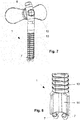
- Figure 4 shows an embodiment of the gas distribution device 3 with two pressure regulating valves 8, which are designed here in the form of a silicone film with two x-shaped slits.
- FIG 5 is one of the execution according to Fig. 4 Identical gas distribution device 3 with additional protective cap 4 is shown.
- the protective cap 4 leaves a gap on the side of the pressure control valve 8, so that an unhindered pressure equalization is made possible.
- FIG Fig. 6 Various embodiments of the cross section of the gas channel 11 in the molded hose 5 are shown in FIG Fig. 6 to see.
- the variant on the far right shows a molded hose 5 with four gas channels 11, each of which has a cross-section in the shape of a sector of a circle.
- the Fig. 7 shows a variant of the nose part 1 with the patient gas supply device 13 and the pressure control valve 8, which is located in the area of the forehead support 12 with adhesive silicone gel.
- the variant of the nose part 1 according to Fig. 8 has the nose bridge contour 14 to which the nasal cannulas 7 are detachably attached.
Landscapes
- Health & Medical Sciences (AREA)
- Pulmonology (AREA)
- Emergency Medicine (AREA)
- Biomedical Technology (AREA)
- Engineering & Computer Science (AREA)
- Anesthesiology (AREA)
- Heart & Thoracic Surgery (AREA)
- Hematology (AREA)
- Life Sciences & Earth Sciences (AREA)
- Animal Behavior & Ethology (AREA)
- General Health & Medical Sciences (AREA)
- Public Health (AREA)
- Veterinary Medicine (AREA)
- Otolaryngology (AREA)
- Respiratory Apparatuses And Protective Means (AREA)
Claims (10)
- Instrument oxythérapeutique pour une oxygénothérapie à haut débit, présentant :- une partie nasale (1) comprenant un canal de gaz pour un gaz de patient et deux canules nasales (7) se trouvant en communication fluidique avec le canal de gaz, chacune avec une ouverture de sortie de gaz de patient,- au moins une soupape de régulation de pression (8) qui est une membrane de silicone dans laquelle au moins deux fentes se croisant sont introduites, par laquelle au moins quatre clapets de soupape mobiles sont formés vers l'extérieur et vers l'intérieur, et- au moins un tube préformé (5), présentant au moins un canal de gaz (11) qui débouche dans une ouverture d'entrée de gaz et une ouverture de sortie de gaz du tube préformé (5), dans lequel le tube préformé (5) débouche avec son ouverture de sortie de gaz dans une ouverture d'entrée de gaz (9) de la partie nasale (1), et- l'instrument oxythérapeutique présente un appareil de répartition de gaz (3) destiné à être raccordé à une source de gaz de patient, dans lequel l'au moins un tube préformé (5) débouche avec son ouverture d'entrée de gaz dans une ouverture de sortie de gaz de l'appareil de répartition de gaz (3),- le tube préformé (5) présente une forme de section transversale de son au moins un canal de gaz (11) qui est en forme d'étoile, de fleur, d'arc de cercle ou de polygone, et- les au moins quatre clapets de soupape mobiles vers l'extérieur et vers l'intérieur de l'au moins une soupape de régulation de pression (8) s'ouvrent proportionnellement à la pression différentielle en présence d'une pression différentielle entre la pression atmosphérique et la pression de gaz dans l'appareil de répartition de gaz (3) et/ou la partie nasale (1) avec une force de ressort inhérente au matériau de clapet de soupape.
- Instrument oxythérapeutique selon la revendication 1, caractérisé en ce que la partie nasale (1) présente au moins une soupape de régulation de pression (8) en communication fluidique avec le canal de gaz.
- Instrument oxythérapeutique selon la revendication 1, caractérisé en ce que l'au moins une vanne de régulation de pression (8) est une partie constituante de l'instrument oxythérapeutique (3).
- Instrument oxythérapeutique selon l'une quelconque des revendications précédentes, caractérisé en ce que les canules nasales (7) présentent un appareil de fuite (10) au niveau de leur ouverture de sortie de gaz de patient.
- Instrument oxythérapeutique selon la revendication 4, caractérisé en ce que le appareil de fuite (10) comprend un anneau disposé concentriquement par rapport à l'axe longitudinal de canules nasales, qui est fixé à l'extérieur de la paroi de la canule nasale (7) au moyen d'écarteurs.
- Instrument oxythérapeutique selon l'une quelconque des revendications précédentes, caractérisé en ce que l'au moins une soupape de régulation de pression (8) est intégrée de façon monolithique dans la partie nasale (1) ou l'appareil de répartition de gaz (3).
- Instrument oxythérapeutique selon la revendication 6, caractérisé en ce que la soupape de régulation de pression (8) est au moins partiellement recouverte de l'extérieur par un capuchon de protection.
- Instrument oxythérapeutique selon l'une quelconque des revendications précédentes, caractérisé en ce qu'il présente deux tubes préformés (5), qui sont respectivement connectés par leur ouverture de sortie de gaz au canal de gaz de la partie nasale (1) et par leur ouverture d'entrée de gaz à l'appareil de répartition de gaz (3), dans lequel les deux tubes préformés (5) sont fixés l'un à l'autre au moyen d'un guide de tube (2) qui peut être déplacé le long des tubes préformés (5).
- Instrument oxythérapeutique selon l'une quelconque des revendications précédentes, caractérisé en ce que le tube préformé (5) contient quatre canaux de gaz (11) qui présentent respectivement une forme de section transversale en forme d'arc de cercle.
- Instrument oxythérapeutique selon l'une quelconque des revendications précédentes, caractérisé en ce que le canal de gaz (11) dans le tube préformé (5) est réalisé en forme hélicoïdale, en ce que la forme de section transversale du canal de gaz (11) est tournée le long de l'axe longitudinal du tube préformé (5).
Applications Claiming Priority (2)
| Application Number | Priority Date | Filing Date | Title |
|---|---|---|---|
| DE102018106161 | 2018-03-16 | ||
| DE102018112903.3A DE102018112903A1 (de) | 2018-03-16 | 2018-05-30 | Sauerstofftherapiegerät |
Publications (2)
| Publication Number | Publication Date |
|---|---|
| EP3539604A1 EP3539604A1 (fr) | 2019-09-18 |
| EP3539604B1 true EP3539604B1 (fr) | 2021-08-11 |
Family
ID=65717760
Family Applications (1)
| Application Number | Title | Priority Date | Filing Date |
|---|---|---|---|
| EP19160749.8A Active EP3539604B1 (fr) | 2018-03-16 | 2019-03-05 | Appareil oxythérapeutique |
Country Status (1)
| Country | Link |
|---|---|
| EP (1) | EP3539604B1 (fr) |
Family Cites Families (4)
| Publication number | Priority date | Publication date | Assignee | Title |
|---|---|---|---|---|
| NZ747465A (en) * | 2008-03-04 | 2020-05-29 | ResMed Pty Ltd | Unobtrusive interface systems |
| WO2013148901A1 (fr) * | 2012-03-28 | 2013-10-03 | Robert Tero | Canule nasale à surveillance de pression et à limitation de pression |
| TR201707036T4 (en) * | 2012-12-04 | 2018-11-21 | Ino Therapeutics Llc | Cannula to minimize dose dilution during administration of nitric oxide |
| NZ732004A (en) * | 2014-06-19 | 2018-11-30 | ResMed Pty Ltd | Patient interface for respiratory therapy |
-
2019
- 2019-03-05 EP EP19160749.8A patent/EP3539604B1/fr active Active
Also Published As
| Publication number | Publication date |
|---|---|
| EP3539604A1 (fr) | 2019-09-18 |
Similar Documents
| Publication | Publication Date | Title |
|---|---|---|
| DE102005014650B3 (de) | Anordnung aus Katheter und Anschlussstück sowie Ventil zum Durchführen eines Katheters | |
| DE2915683C2 (de) | Zweiwegeventil für den Anschluß eines Patienten an ein Atmungsgerät | |
| DE2147508A1 (de) | Endotracheale Röhre und Verbindungseinheit | |
| DE69329711T2 (de) | Atmungsunterstützungssystem | |
| DE69330517T2 (de) | Trachealtubus mit flexiblem segment | |
| WO2007107526A1 (fr) | Dispositif d'amenee directe de gaz respiratoire dans le nez d'un utilisateur | |
| EP3624883B1 (fr) | Soupape d'expiration d'un dispositif respiratoire avec résistance à l'écoulement minimisant les bruits | |
| EP3624884B1 (fr) | Ensemble clapet d'expiration pour un dispositif respiratoire, doté d'un dispositif pour recevoir un capteur de pression | |
| DE4204159A1 (de) | Wiederbelebungsgeraet mit einem die stroemungsrichtung kontrollierenden ventil mit einem inneren "peep"-justierventil | |
| DE2312071A1 (de) | Apparat zur kuenstlichen beatmung | |
| DE112015001488T5 (de) | Unterdruckmasken, Systeme und Verfahren | |
| EP2931343B1 (fr) | Dispositif compensateur de pression | |
| DE10046872B4 (de) | Atmungsunterstützungsvorrichtung | |
| EP2931345B1 (fr) | Ballonnet de compensation de pression et son procédé de fabrication | |
| DE102017008791B4 (de) | Beatmungsgerät mit einer Steuerungseinheit | |
| EP2046431B1 (fr) | Canule de tracheotomie avec canule interne | |
| EP3967351B1 (fr) | Jupe de masque pourvu de passage de tuyau | |
| EP3539604B1 (fr) | Appareil oxythérapeutique | |
| DE3028568C2 (de) | Endotrachealtubus | |
| DE102018112903A1 (de) | Sauerstofftherapiegerät | |
| EP3858413B1 (fr) | Unité de liaison courbée destinée à la liaison d'une unité d'accouplement du côté d'un patient à un appareil médical | |
| WO2019229227A1 (fr) | Adaptateur de tube endotrachéal | |
| DE102020123654A1 (de) | Pneumatikmodul sowie Verfahren zur Versorgung eines Verbrauchers mit einem druckstoßfreien Strom medizinischen Gases oder medizinischer Luft | |
| DE102021101726A1 (de) | Endstück für eine Nasenkanülenanordnung, Kanülenbaustein, Verbindungseinheit und Beatmungsgerät | |
| DE202017003898U1 (de) | Beatmungsfilter für ein Tracheostoma |
Legal Events
| Date | Code | Title | Description |
|---|---|---|---|
| PUAI | Public reference made under article 153(3) epc to a published international application that has entered the european phase |
Free format text: ORIGINAL CODE: 0009012 |
|
| STAA | Information on the status of an ep patent application or granted ep patent |
Free format text: STATUS: THE APPLICATION HAS BEEN PUBLISHED |
|
| AK | Designated contracting states |
Kind code of ref document: A1 Designated state(s): AL AT BE BG CH CY CZ DE DK EE ES FI FR GB GR HR HU IE IS IT LI LT LU LV MC MK MT NL NO PL PT RO RS SE SI SK SM TR |
|
| AX | Request for extension of the european patent |
Extension state: BA ME |
|
| STAA | Information on the status of an ep patent application or granted ep patent |
Free format text: STATUS: REQUEST FOR EXAMINATION WAS MADE |
|
| 17P | Request for examination filed |
Effective date: 20200311 |
|
| RBV | Designated contracting states (corrected) |
Designated state(s): AL AT BE BG CH CY CZ DE DK EE ES FI FR GB GR HR HU IE IS IT LI LT LU LV MC MK MT NL NO PL PT RO RS SE SI SK SM TR |
|
| GRAP | Despatch of communication of intention to grant a patent |
Free format text: ORIGINAL CODE: EPIDOSNIGR1 |
|
| STAA | Information on the status of an ep patent application or granted ep patent |
Free format text: STATUS: GRANT OF PATENT IS INTENDED |
|
| INTG | Intention to grant announced |
Effective date: 20210301 |
|
| GRAS | Grant fee paid |
Free format text: ORIGINAL CODE: EPIDOSNIGR3 |
|
| GRAA | (expected) grant |
Free format text: ORIGINAL CODE: 0009210 |
|
| STAA | Information on the status of an ep patent application or granted ep patent |
Free format text: STATUS: THE PATENT HAS BEEN GRANTED |
|
| AK | Designated contracting states |
Kind code of ref document: B1 Designated state(s): AL AT BE BG CH CY CZ DE DK EE ES FI FR GB GR HR HU IE IS IT LI LT LU LV MC MK MT NL NO PL PT RO RS SE SI SK SM TR |
|
| REG | Reference to a national code |
Ref country code: CH Ref legal event code: EP |
|
| REG | Reference to a national code |
Ref country code: DE Ref legal event code: R096 Ref document number: 502019001983 Country of ref document: DE |
|
| REG | Reference to a national code |
Ref country code: IE Ref legal event code: FG4D Free format text: LANGUAGE OF EP DOCUMENT: GERMAN Ref country code: AT Ref legal event code: REF Ref document number: 1418740 Country of ref document: AT Kind code of ref document: T Effective date: 20210915 |
|
| REG | Reference to a national code |
Ref country code: SE Ref legal event code: TRGR |
|
| REG | Reference to a national code |
Ref country code: NL Ref legal event code: FP |
|
| REG | Reference to a national code |
Ref country code: LT Ref legal event code: MG9D |
|
| PG25 | Lapsed in a contracting state [announced via postgrant information from national office to epo] |
Ref country code: BG Free format text: LAPSE BECAUSE OF FAILURE TO SUBMIT A TRANSLATION OF THE DESCRIPTION OR TO PAY THE FEE WITHIN THE PRESCRIBED TIME-LIMIT Effective date: 20211111 Ref country code: LT Free format text: LAPSE BECAUSE OF FAILURE TO SUBMIT A TRANSLATION OF THE DESCRIPTION OR TO PAY THE FEE WITHIN THE PRESCRIBED TIME-LIMIT Effective date: 20210811 Ref country code: NO Free format text: LAPSE BECAUSE OF FAILURE TO SUBMIT A TRANSLATION OF THE DESCRIPTION OR TO PAY THE FEE WITHIN THE PRESCRIBED TIME-LIMIT Effective date: 20211111 Ref country code: PT Free format text: LAPSE BECAUSE OF FAILURE TO SUBMIT A TRANSLATION OF THE DESCRIPTION OR TO PAY THE FEE WITHIN THE PRESCRIBED TIME-LIMIT Effective date: 20211213 Ref country code: HR Free format text: LAPSE BECAUSE OF FAILURE TO SUBMIT A TRANSLATION OF THE DESCRIPTION OR TO PAY THE FEE WITHIN THE PRESCRIBED TIME-LIMIT Effective date: 20210811 Ref country code: RS Free format text: LAPSE BECAUSE OF FAILURE TO SUBMIT A TRANSLATION OF THE DESCRIPTION OR TO PAY THE FEE WITHIN THE PRESCRIBED TIME-LIMIT Effective date: 20210811 Ref country code: ES Free format text: LAPSE BECAUSE OF FAILURE TO SUBMIT A TRANSLATION OF THE DESCRIPTION OR TO PAY THE FEE WITHIN THE PRESCRIBED TIME-LIMIT Effective date: 20210811 Ref country code: FI Free format text: LAPSE BECAUSE OF FAILURE TO SUBMIT A TRANSLATION OF THE DESCRIPTION OR TO PAY THE FEE WITHIN THE PRESCRIBED TIME-LIMIT Effective date: 20210811 |
|
| PG25 | Lapsed in a contracting state [announced via postgrant information from national office to epo] |
Ref country code: PL Free format text: LAPSE BECAUSE OF FAILURE TO SUBMIT A TRANSLATION OF THE DESCRIPTION OR TO PAY THE FEE WITHIN THE PRESCRIBED TIME-LIMIT Effective date: 20210811 Ref country code: LV Free format text: LAPSE BECAUSE OF FAILURE TO SUBMIT A TRANSLATION OF THE DESCRIPTION OR TO PAY THE FEE WITHIN THE PRESCRIBED TIME-LIMIT Effective date: 20210811 Ref country code: GR Free format text: LAPSE BECAUSE OF FAILURE TO SUBMIT A TRANSLATION OF THE DESCRIPTION OR TO PAY THE FEE WITHIN THE PRESCRIBED TIME-LIMIT Effective date: 20211112 |
|
| PG25 | Lapsed in a contracting state [announced via postgrant information from national office to epo] |
Ref country code: DK Free format text: LAPSE BECAUSE OF FAILURE TO SUBMIT A TRANSLATION OF THE DESCRIPTION OR TO PAY THE FEE WITHIN THE PRESCRIBED TIME-LIMIT Effective date: 20210811 |
|
| REG | Reference to a national code |
Ref country code: DE Ref legal event code: R097 Ref document number: 502019001983 Country of ref document: DE |
|
| PG25 | Lapsed in a contracting state [announced via postgrant information from national office to epo] |
Ref country code: SM Free format text: LAPSE BECAUSE OF FAILURE TO SUBMIT A TRANSLATION OF THE DESCRIPTION OR TO PAY THE FEE WITHIN THE PRESCRIBED TIME-LIMIT Effective date: 20210811 Ref country code: SK Free format text: LAPSE BECAUSE OF FAILURE TO SUBMIT A TRANSLATION OF THE DESCRIPTION OR TO PAY THE FEE WITHIN THE PRESCRIBED TIME-LIMIT Effective date: 20210811 Ref country code: RO Free format text: LAPSE BECAUSE OF FAILURE TO SUBMIT A TRANSLATION OF THE DESCRIPTION OR TO PAY THE FEE WITHIN THE PRESCRIBED TIME-LIMIT Effective date: 20210811 Ref country code: EE Free format text: LAPSE BECAUSE OF FAILURE TO SUBMIT A TRANSLATION OF THE DESCRIPTION OR TO PAY THE FEE WITHIN THE PRESCRIBED TIME-LIMIT Effective date: 20210811 Ref country code: CZ Free format text: LAPSE BECAUSE OF FAILURE TO SUBMIT A TRANSLATION OF THE DESCRIPTION OR TO PAY THE FEE WITHIN THE PRESCRIBED TIME-LIMIT Effective date: 20210811 Ref country code: AL Free format text: LAPSE BECAUSE OF FAILURE TO SUBMIT A TRANSLATION OF THE DESCRIPTION OR TO PAY THE FEE WITHIN THE PRESCRIBED TIME-LIMIT Effective date: 20210811 |
|
| PLBE | No opposition filed within time limit |
Free format text: ORIGINAL CODE: 0009261 |
|
| STAA | Information on the status of an ep patent application or granted ep patent |
Free format text: STATUS: NO OPPOSITION FILED WITHIN TIME LIMIT |
|
| 26N | No opposition filed |
Effective date: 20220512 |
|
| PG25 | Lapsed in a contracting state [announced via postgrant information from national office to epo] |
Ref country code: IT Free format text: LAPSE BECAUSE OF FAILURE TO SUBMIT A TRANSLATION OF THE DESCRIPTION OR TO PAY THE FEE WITHIN THE PRESCRIBED TIME-LIMIT Effective date: 20210811 |
|
| PG25 | Lapsed in a contracting state [announced via postgrant information from national office to epo] |
Ref country code: SI Free format text: LAPSE BECAUSE OF FAILURE TO SUBMIT A TRANSLATION OF THE DESCRIPTION OR TO PAY THE FEE WITHIN THE PRESCRIBED TIME-LIMIT Effective date: 20210811 |
|
| PG25 | Lapsed in a contracting state [announced via postgrant information from national office to epo] |
Ref country code: MC Free format text: LAPSE BECAUSE OF FAILURE TO SUBMIT A TRANSLATION OF THE DESCRIPTION OR TO PAY THE FEE WITHIN THE PRESCRIBED TIME-LIMIT Effective date: 20210811 |
|
| PG25 | Lapsed in a contracting state [announced via postgrant information from national office to epo] |
Ref country code: LU Free format text: LAPSE BECAUSE OF NON-PAYMENT OF DUE FEES Effective date: 20220305 Ref country code: IE Free format text: LAPSE BECAUSE OF NON-PAYMENT OF DUE FEES Effective date: 20220305 |
|
| PGFP | Annual fee paid to national office [announced via postgrant information from national office to epo] |
Ref country code: NL Payment date: 20240320 Year of fee payment: 6 |
|
| PGFP | Annual fee paid to national office [announced via postgrant information from national office to epo] |
Ref country code: AT Payment date: 20240318 Year of fee payment: 6 |
|
| PG25 | Lapsed in a contracting state [announced via postgrant information from national office to epo] |
Ref country code: MK Free format text: LAPSE BECAUSE OF FAILURE TO SUBMIT A TRANSLATION OF THE DESCRIPTION OR TO PAY THE FEE WITHIN THE PRESCRIBED TIME-LIMIT Effective date: 20210811 Ref country code: CY Free format text: LAPSE BECAUSE OF FAILURE TO SUBMIT A TRANSLATION OF THE DESCRIPTION OR TO PAY THE FEE WITHIN THE PRESCRIBED TIME-LIMIT Effective date: 20210811 |
|
| PGFP | Annual fee paid to national office [announced via postgrant information from national office to epo] |
Ref country code: DE Payment date: 20240125 Year of fee payment: 6 Ref country code: GB Payment date: 20240322 Year of fee payment: 6 |
|
| PG25 | Lapsed in a contracting state [announced via postgrant information from national office to epo] |
Ref country code: HU Free format text: LAPSE BECAUSE OF FAILURE TO SUBMIT A TRANSLATION OF THE DESCRIPTION OR TO PAY THE FEE WITHIN THE PRESCRIBED TIME-LIMIT; INVALID AB INITIO Effective date: 20190305 |
|
| PGFP | Annual fee paid to national office [announced via postgrant information from national office to epo] |
Ref country code: SE Payment date: 20240321 Year of fee payment: 6 Ref country code: FR Payment date: 20240320 Year of fee payment: 6 Ref country code: BE Payment date: 20240320 Year of fee payment: 6 |
|
| PG25 | Lapsed in a contracting state [announced via postgrant information from national office to epo] |
Ref country code: TR Free format text: LAPSE BECAUSE OF FAILURE TO SUBMIT A TRANSLATION OF THE DESCRIPTION OR TO PAY THE FEE WITHIN THE PRESCRIBED TIME-LIMIT Effective date: 20210811 |
|
| PGFP | Annual fee paid to national office [announced via postgrant information from national office to epo] |
Ref country code: CH Payment date: 20240401 Year of fee payment: 6 |
|
| PG25 | Lapsed in a contracting state [announced via postgrant information from national office to epo] |
Ref country code: MT Free format text: LAPSE BECAUSE OF FAILURE TO SUBMIT A TRANSLATION OF THE DESCRIPTION OR TO PAY THE FEE WITHIN THE PRESCRIBED TIME-LIMIT Effective date: 20210811 |
|
| REG | Reference to a national code |
Ref country code: DE Ref legal event code: R119 Ref document number: 502019001983 Country of ref document: DE |
|
| REG | Reference to a national code |
Ref country code: CH Ref legal event code: H13 Free format text: ST27 STATUS EVENT CODE: U-0-0-H10-H13 (AS PROVIDED BY THE NATIONAL OFFICE) Effective date: 20251023 |
|
| REG | Reference to a national code |
Ref country code: SE Ref legal event code: EUG |
|
| REG | Reference to a national code |
Ref country code: NL Ref legal event code: MM Effective date: 20250401 |
|
| REG | Reference to a national code |
Ref country code: AT Ref legal event code: MM01 Ref document number: 1418740 Country of ref document: AT Kind code of ref document: T Effective date: 20250305 |
|
| GBPC | Gb: european patent ceased through non-payment of renewal fee |
Effective date: 20250305 |
|
| REG | Reference to a national code |
Ref country code: BE Ref legal event code: MM Effective date: 20250331 |
|
| PG25 | Lapsed in a contracting state [announced via postgrant information from national office to epo] |
Ref country code: NL Free format text: LAPSE BECAUSE OF NON-PAYMENT OF DUE FEES Effective date: 20250401 |
|
| PG25 | Lapsed in a contracting state [announced via postgrant information from national office to epo] |
Ref country code: DE Free format text: LAPSE BECAUSE OF NON-PAYMENT OF DUE FEES Effective date: 20251001 |
|
| PG25 | Lapsed in a contracting state [announced via postgrant information from national office to epo] |
Ref country code: GB Free format text: LAPSE BECAUSE OF NON-PAYMENT OF DUE FEES Effective date: 20250305 |
|
| PG25 | Lapsed in a contracting state [announced via postgrant information from national office to epo] |
Ref country code: AT Free format text: LAPSE BECAUSE OF NON-PAYMENT OF DUE FEES Effective date: 20250305 |
|
| PG25 | Lapsed in a contracting state [announced via postgrant information from national office to epo] |
Ref country code: FR Free format text: LAPSE BECAUSE OF NON-PAYMENT OF DUE FEES Effective date: 20250331 |
|
| PG25 | Lapsed in a contracting state [announced via postgrant information from national office to epo] |
Ref country code: BE Free format text: LAPSE BECAUSE OF NON-PAYMENT OF DUE FEES Effective date: 20250331 |
|
| PG25 | Lapsed in a contracting state [announced via postgrant information from national office to epo] |
Ref country code: CH Free format text: LAPSE BECAUSE OF NON-PAYMENT OF DUE FEES Effective date: 20250331 |
|
| PG25 | Lapsed in a contracting state [announced via postgrant information from national office to epo] |
Ref country code: SE Free format text: LAPSE BECAUSE OF NON-PAYMENT OF DUE FEES Effective date: 20250306 |