EP3539734A1 - Antriebsmechanismus, robotervorrichtungsmessverfahren, robotervorrichtungssteuerungsverfahren und komponentenherstellungsverfahren - Google Patents
Antriebsmechanismus, robotervorrichtungsmessverfahren, robotervorrichtungssteuerungsverfahren und komponentenherstellungsverfahren Download PDFInfo
- Publication number
- EP3539734A1 EP3539734A1 EP19165638.8A EP19165638A EP3539734A1 EP 3539734 A1 EP3539734 A1 EP 3539734A1 EP 19165638 A EP19165638 A EP 19165638A EP 3539734 A1 EP3539734 A1 EP 3539734A1
- Authority
- EP
- European Patent Office
- Prior art keywords
- force
- joint
- sensor
- link
- driving
- Prior art date
- Legal status (The legal status is an assumption and is not a legal conclusion. Google has not performed a legal analysis and makes no representation as to the accuracy of the status listed.)
- Granted
Links
Images


Classifications
-
- B—PERFORMING OPERATIONS; TRANSPORTING
- B25—HAND TOOLS; PORTABLE POWER-DRIVEN TOOLS; MANIPULATORS
- B25J—MANIPULATORS; CHAMBERS PROVIDED WITH MANIPULATION DEVICES
- B25J17/00—Joints
- B25J17/02—Wrist joints
-
- B—PERFORMING OPERATIONS; TRANSPORTING
- B25—HAND TOOLS; PORTABLE POWER-DRIVEN TOOLS; MANIPULATORS
- B25J—MANIPULATORS; CHAMBERS PROVIDED WITH MANIPULATION DEVICES
- B25J9/00—Program-controlled manipulators
- B25J9/16—Program controls
- B25J9/1694—Program controls characterised by use of sensors other than normal servo-feedback from position, speed or acceleration sensors, perception control, multi-sensor controlled systems, sensor fusion
-
- B—PERFORMING OPERATIONS; TRANSPORTING
- B25—HAND TOOLS; PORTABLE POWER-DRIVEN TOOLS; MANIPULATORS
- B25J—MANIPULATORS; CHAMBERS PROVIDED WITH MANIPULATION DEVICES
- B25J9/00—Program-controlled manipulators
- B25J9/16—Program controls
- B25J9/1628—Program controls characterised by the control loop
- B25J9/1633—Program controls characterised by the control loop compliant, force, torque control, e.g. combined with position control
-
- B—PERFORMING OPERATIONS; TRANSPORTING
- B25—HAND TOOLS; PORTABLE POWER-DRIVEN TOOLS; MANIPULATORS
- B25J—MANIPULATORS; CHAMBERS PROVIDED WITH MANIPULATION DEVICES
- B25J13/00—Controls for manipulators
- B25J13/08—Controls for manipulators by means of sensing devices, e.g. viewing or touching devices
- B25J13/085—Force or torque sensors
-
- B—PERFORMING OPERATIONS; TRANSPORTING
- B25—HAND TOOLS; PORTABLE POWER-DRIVEN TOOLS; MANIPULATORS
- B25J—MANIPULATORS; CHAMBERS PROVIDED WITH MANIPULATION DEVICES
- B25J17/00—Joints
-
- G—PHYSICS
- G05—CONTROLLING; REGULATING
- G05B—CONTROL OR REGULATING SYSTEMS IN GENERAL; FUNCTIONAL ELEMENTS OF SUCH SYSTEMS; MONITORING OR TESTING ARRANGEMENTS FOR SUCH SYSTEMS OR ELEMENTS
- G05B2219/00—Program-control systems
- G05B2219/30—Nc systems
- G05B2219/37—Measurements
- G05B2219/37581—Measuring errors
-
- G—PHYSICS
- G05—CONTROLLING; REGULATING
- G05B—CONTROL OR REGULATING SYSTEMS IN GENERAL; FUNCTIONAL ELEMENTS OF SUCH SYSTEMS; MONITORING OR TESTING ARRANGEMENTS FOR SUCH SYSTEMS OR ELEMENTS
- G05B2219/00—Program-control systems
- G05B2219/30—Nc systems
- G05B2219/40—Robotics, robotics mapping to robotics vision
- G05B2219/40536—Signal processing for sensors
-
- G—PHYSICS
- G05—CONTROLLING; REGULATING
- G05B—CONTROL OR REGULATING SYSTEMS IN GENERAL; FUNCTIONAL ELEMENTS OF SUCH SYSTEMS; MONITORING OR TESTING ARRANGEMENTS FOR SUCH SYSTEMS OR ELEMENTS
- G05B2219/00—Program-control systems
- G05B2219/30—Nc systems
- G05B2219/40—Robotics, robotics mapping to robotics vision
- G05B2219/40559—Collision between hand and workpiece, operator
-
- G—PHYSICS
- G05—CONTROLLING; REGULATING
- G05B—CONTROL OR REGULATING SYSTEMS IN GENERAL; FUNCTIONAL ELEMENTS OF SUCH SYSTEMS; MONITORING OR TESTING ARRANGEMENTS FOR SUCH SYSTEMS OR ELEMENTS
- G05B2219/00—Program-control systems
- G05B2219/30—Nc systems
- G05B2219/40—Robotics, robotics mapping to robotics vision
- G05B2219/40587—Measure force indirectly by using deviation in position
Definitions
- the present invention relates to a driving mechanism including a sensor that measures force acting on a link joined to the driving mechanism, a robot apparatus measurement method and a robot apparatus control method, and a component manufacturing method.
- multijoint robots have been used on various industrial product production lines.
- processes that are difficult to perform with multijoint robots.
- multijoint robots are widely used particularly in processes in which a load of several hundred grams to several kilograms is imposed on a component.
- there are various difficulties in performing processes requiring a load provided to a component to be around several grams such as attachment of a work including, e.g., a soft object, a lightweight object or a low-strength member and processes for providing a precise fit with multijoint robots.
- a configuration in which a force sensor is disposed together with an end-effector such as a hand or a gripper attached to a distal end of a multijoint robot has conventionally been known.
- An output value from this force sensor is fed-back for driving control of the end-effector, whereby force acting on a work can be controlled.
- forces acting on respective links included in an arm of the multijoint robot are measured and fed back for driving control of the multijoint robot.
- a force that is necessary to be measured for high-precision driving control of a multijoint robot from among forces acting on links of a robot arm is a torque acting around a driving axis.
- Gravitational force, inertial force and/or Coriolis force which act on a link itself, and/or force from an adjacent link act on a joint of a multijoint robot arm depending on a motion of the arm.
- the forces acting on the joint include respective components of a total of forces in six directions including translational forces in three coordinate axis directions and rotative forces around three coordinate axes in an orthogonal coordinate system where a driving axis of the joint is a z-axis.
- forces acting in five directions other than a force acting around the driving axis of the joint is referred to as a force in another axial direction.
- a force around a driving axis of a joint the force acting on a link
- a force sensor mounted on a joint can correctly detect a force around a driving axis of the joint, the force acting on a link joined to the joint.
- the force sensor fails to correctly detect a force around a driving axis.
- a force in another axial direction acts on a force sensor of a type that includes a deformable part and determines the force by detecting an amount of deformation occurred in the deformable part
- the force sensor deforms also in a circumferential direction of the driving axis of the joint from the effect of the force in the other axial direction.
- interference in another axial direction the effect of the force in the other axial direction on the force sensor is referred to as "interference in another axial direction”.
- the deformation appears as a detection error of the force sensor that detects a force around the driving axis of the joint.
- a measurement error caused in a force sensor provided on a driving axis of a certain joint by a force in another axial direction as stated above is referred to as “interference in another axial direction”. If such interference in another axial direction occurs, it is impossible to correctly detect a force around the driving axis of the joint with the force sensor.
- a reason of difficulty in detection of a value of a force in another axial direction where a mechanical element such as a bearing is interposed at a joint of a multijoint robot arm like the conventional configuration in Japanese Patent Application Laid-Open No. 2011-72186 is provided below.
- this type of joint structure allows motion of a joint in a desired one direction only, and uses a bearing such as a cross roller bearing as a constraining unit (constraining part) for constraining motion in another direction.
- a bearing such as a cross roller bearing
- constraining unit constraining part
- Such structure may result in complexity of a transfer pathway of a force in another axial direction.
- a pathway on which a joint driving force is transferred other than a joint axis connecting two links there may be a pathway on which a joint driving force is transferred other than a joint axis connecting two links.
- a force in another axial direction acting on a drive-side link is transferred via both a bearing, which is a constraining unit of the joint, and the force sensor. With such configuration, it is difficult to obtain a correct value of the force in another axial direction transferred to the force sensor.
- a driving force of a link reduced by the amount of a frictional force of a bearing, which is a constraining part of a joint is transferred to a force sensor.
- a frictional force of a bearing of a joint exhibits non-linear characteristics relative to various factors such as a force acting on the bearing, a driving speed of the joint and an individual specificity of the bearing, and thus it is difficult to correctly grape a frictional force of a bearing.
- the present invention enables accurate detection of a force in another axial direction acting on a joint of a robot arm, and thus enables correction of a detection error of a force sensor caused by interference in another axial direction and accurate detection of a force acting on a link joined to the joint.
- a driving mechanism for driving a first link and a second link relative to each other comprises: a driving apparatus that includes a fixed part and a part to be driven and drives the part to be driven relative to the fixed part; and a constraining part that includes a first supporting part and a second supporting part and constrains the first link and the second link so as to be movable in a desired direction and be unmovable in another direction, wherein one of the fixed part and the part to be driven is fixed to the first link; the first supporting part is fixed to the first link; the second supporting part is fixed to another of the fixed part and the part to be driven; and a sensor for determining force acting on the second link is attached so as to link the other of the fixed part and the part to be driven and the second link.
- the present invention enables simplification of a transfer pathway of a force in another axial direction applied to a force sensor.
- a value of a force in another axial direction applied to the force sensor can be grasped with high precision, and consequently, a sensor detected value error caused by interference in another axial direction can be corrected with high precision, enabling high-precision sensor detected value correction.
- Use of the corrected sensor detected value for driving control of the multijoint robot enables high-precision driving control and thus enables the multijoint robot to perform a process that has conventionally been difficult to perform with a multijoint robot.
- the corrected sensor detected value for driving control of the multijoint robot enables high-precision control of a force provided to a component by an end-effector attached to a distal end of the multijoint robot. Consequently, a process requiring a load provided to a component to be around several grams such as a process for attachment of a soft object or a low-strength member can be automated by a multijoint robot.
- a sensor having a function that determines a force acting around a driving axis of a joint is referred to as a force sensor.
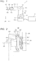
- FIG. 1 illustrates a basic configuration of a multijoint robot system to which the present embodiment can be applied.
- the robot system in FIG. 1 includes a robot arm 1 configured, for example, as a multijoint robot arm, and a robot control apparatus 2 that controls the robot arm 1.
- the robot arm 1 is a multijoint robot arm having a vertical six-axis configuration.
- the robot arm 1 includes first to sixth links 111 to 116 joined via first to sixth joints 121 to 126 on a base 110.
- the base 110 and the first link 111 of the robot arm 1 are connected by a joint 121 that rotates around a rotary axis in a Z-axis direction.
- the first link 111 and the second link 112 of the robot arm 1 are connected by a joint 122 that rotates around a rotary axis in a Y-axis direction.
- the second link 112 and the third link 113 of the robot arm 1 are connected by a joint 123 that rotates around a rotary axis in the Y-axis direction.
- the third link 113 and the fourth link 114 of the robot arm 1 are connected by a joint 124 that rotates around a rotary axis in an X-axis direction.
- the fourth link 114 and the fifth link 115 of the robot arm 1 are connected by a joint 125 that rotates around a rotary axis in the Y-axis direction.
- the fifth link 115 and the sixth link 116 of the robot arm 1 are connected by a joint 126 that rotates around a rotary axis in the X-axis direction.
- An end-effector 117 such as a motor hand or an air-powered hand for performing component assembling work or component transfer work on a production line is connected to a tip of the sixth link 116 of the robot arm 1.
- Motion of the robot arm 1 is controlled by the robot control apparatus 2.
- the robot control apparatus 2 controls a pose (position and orientation) of each joint of the robot arm 1 according to a preprogramed robot control program, whereby a pose of the robot arm 1 or a position and a pose of a reference site set in the vicinity of the end-effector 117 is controlled.
- the robot control apparatus 2 can manipulate a work using the robot arm 1 by controlling motion of the end-effector 117, for example, a motion such as opening/closing of the hand. Consequently, a component can be manufactured.
- FIG. 1 three-dimensional coordinate axes for the entire robot arm 1 are indicated in the lower left part.
- the robot arm 1 in FIG. 1 is illustrated in a pose in which the first joint 121 makes the adjacent link rotate around the rotary axis in the Z-axis direction, and the second joint 122, the third joint 123 and the fifth joint 125 make the respective adjacent links rotate around the respective rotary axes in the Y-axis direction.
- the fourth joint 124 and sixth joint 126 are configured to make the respective adjacent links rotate around the respective rotary axes in the X-axis direction.
- a relationship between the rotary axis of each of the joints and the relevant coordinate axis is one that is applicable to the pose of the robot arm 1 in FIG. 1 . Therefore, for example, use of another coordinate system may be needed if the robot arm 1 is controlled to be in a pose that is different from that of FIG. 1 by the robot control apparatus 2.
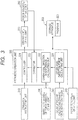
- FIG. 2 schematically illustrates an example basic structure of a joint in the robot arm 1 in FIG. 1 .
- n-th joint an arbitrary joint from among the first to sixth joints 121 to 126 may be referred to as "n-th joint". Also, in order to indicate this "n-th (joint; the same applies to "link”)" more simply, indications of reference numerals in the figure with a subscript "n" prefixed is used. Also, a joint adjacent to the "n-th” joint on the end side of the arm may be indicated as an "n+1" joint, and a joint adjacent to the "n-th” joint on the base side may be indicated as an "n-1" joint. In the arm configuration in FIG. 1 , n corresponds to the number of a joint (or a link) of the robot arm 1 and may take the value of 1 to 6. Also, in order to avoid complexity, an indication of the letter n may be omitted in the figure.
- FIG. 2 illustrates a driving mechanism included in a joint joining the first and second links (210, 220) so as to be movable relative to each other.
- the driving mechanism in FIG. 2 includes a sensor for determining force acting on the first and second link (210, 220).
- an n-th joint joins an n-1-th link 210 and an n-th link 220.
- the n-th joint includes a driving unit n230 that drives the n-th joint and a constraining part n240 that constrains motion of the n-th joint.
- the n-th joint includes a force sensor n 250 that detects a force exerted on links joined via the n-th joint.
- n-1-th link 210 and the n-th link 220 are joined via this joint so as to be movable relative to each other, and respective poses of the n-1-th link 210 and the n-th link 220 are controlled by a driving force generated by the driving unit n 230.
- the driving unit n 230 that generates a driving force of the joint includes a fixed part 231 and a part to be driven 232 as a first driving part and a second driving part, respectively.
- the driving unit of this type of robot joint includes, for example, an electric motor and a reducer. Rotation of an output shaft of the electric motor is input to the reducer, and the rotation of the output shaft of the electric motor is reduced at a predetermined reduction ratio and is transferred to the part to be driven 232.
- a strain wave gearing is used for the reducer of the driving unit n 230.
- the constraining part n 240 has a function that constrains respective a direction of relative movement of the first and second links in such a manner that the first and second links are movable in a direction in which the joint is driven and are unmovable in the other directions.
- the constraining part n 240 constrains motion of the joint in such a manner that the joint is movable only around a driving axis n 200 of the n-th joint and is unmovable in the other directions.
- the constraining part n 240 can include, for example, a cross roller bearing 241 and a connecting member 244 fixed to an inner race 242 of the cross roller bearing 241.
- the inner race 242 and an outer race 243 of the cross roller bearing 241 are disposed at respective positions at which the inner race 242 and the outer race 243 are rotatable around the driving axis n 200.
- the inner race 242 and the outer race 243 of the cross roller bearing 241 included in the constraining part n 240 correspond to a first supporting part and a second supporting part of the constraining part n 240.
- the force sensor n 250 includes, for example, a torque sensor that measures a displacement in order to determine a force around the driving axis n 200 of the joint, the force being applied to the torque sensor itself.
- the force sensor n 250 includes, for example, an inner race part 251, an outer race part 252, and a spring part 253 linking the inner race part 251 and the outer race part 252.
- a sensitivity matrix (n330, which will be described later) for converting a deformation amount of the force sensor n 250 into a force is provided in advance in the form of, e.g., a table memory, whereby a measured deformation amount can be converted into a measurement amount of a force.
- a force sensor displacement detection method for measuring an amount of deformation of the force sensor n 250 include, e.g., a strain gauge method, a capacitance method, a magnetic method and an optical encoder method.
- the optical encoder method a configuration in which a scale of an optical rotary encoder and an optical sensor (not illustrated) are disposed so as to face the connecting member 244 and the outer race part 252, respectively.
- FIG. 7 members having a disposition (linkage or joining) relationship corresponding to that of FIG. 2 are provided with reference numerals that are the same as those of FIG. 2 .
- a force sensor n 250 is disposed at a position that is different from that of FIG. 2
- the linkage (joining) relationship among the respective parts of the joint structure is similar to that of the joint in FIG. 2 .
- positions of links 210 and 220 are switched from each other so as to correspond to the first and second links in the linkage (joining) relationship described in (i) to (iv) above.
- a positional relationship between a fixed part 231 (first driving part) of a driving unit n 230 and a part to be driven 232 (second driving part) is opposite to that of FIG. 2 .
- an outer race 243 of a cross roller bearing 241 corresponds to the second supporting part of the constraining part in (i) to (iv) above
- an inner race 242 corresponds to the first supporting part of the constraining part in (i) to (iv) above.
- the connecting member 244 in (i) to (iv) above corresponds to a cylindrical housing part covering the driving unit n 230 in FIG. 7 .
- An inner race part 251 of the force sensor n 250 is fixed to the connecting member 244, and an outer race part 252 of the force sensor n 250 is fixed to the link 220 (second link).
- the joint structure in FIG. 7 satisfies the linkage (joining) relationship described in (i) to (iv) above.
- the structure in FIG. 7 also enables joint driving force measurement and joint driving control, which will be described later, and can be expected to provide operation and effects similar to those of the joint structure in FIG. 2 (described later).
- FIG. 2 indicates a structure in which the links rotationally move relative to each other; however, in the case of a slider joint that linearly moves links relative to each other, the structure in FIG. 8 may be employed.
- members having a disposition relationship corresponding to that of FIG. 2 (or FIG. 7 ) are provided with reference numerals that are the same as those of FIG. 2 (or FIG. 7 ).
- a reference numeral correspondence between FIGS. 8 and 2 is similar to that in the case of FIG. 7 above and thus is not described repeatedly, even though the joint structure in FIG. 8 is a slider joint, a linkage (joining) relationship among respective parts of the joint structure is equivalent to that of FIG. 2 ( FIG. 7 ) described in (i) to (iv) above.
- the plurality of joints of the robot arm 1 configured as illustrated in FIG. 2 is controlled by the robot control apparatus 2.
- the robot control apparatus 2 controls respective angles of n-th joints (first to sixth joints 121 to 126) and thereby can cause the robot arm 1 to take a desired pose.
- the robot control apparatus 2 can control, for example, a force applied on a work (not illustrated) manipulated via the end-effector 117.
- the robot control apparatus 2 can receive inputs of measured values from force sensors disposed at respective joints (n) of the robot arm 1 and feed the measured values back to the driving units n 230 of the respective joints. Consequently, for example, feedback control such as controlling a force applied to a work to be a desired magnitude or performing control to prevent a force having a predetermined magnitude or more from being applied to a work can be performed.
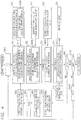
- FIG. 3 illustrates a configuration of a control system for an n-th joint of the robot arm 1 in the robot control apparatus 2 as a function block diagram.
- a major part includes an arithmetic operation unit 320 and a storage apparatus 300.
- the arithmetic operation unit 320 can include a computer, for example, a CPU including, e.g., a general-purpose microprocessor.
- a storage device used for the storage apparatus 300 include semiconductor memories such as a ROM and a RAM and fixed (external) storage apparatuses such as an HDD and an SSD.
- a configuration using a rewritable recording medium such as any of various flash memories or optical (magnetic) disks is conceivable.
- the storage apparatus 300 can include an arbitrary combination of these storage devices.
- the storage device included in the storage apparatus 300 provides a recording medium that the arithmetic operation unit 320 (computer) can read.
- a program 301 in which a later-described control procedure to be executed by the arithmetic operation unit 320 (computer) that provides the control apparatus for the robot arm 1 is written can be stored.
- information necessary for making the robot arm 1 manipulate works to, for example, assemble and manufacture a certain industrial product can be stored in the form of, for example, a robot control program.
- the robot control program is written in the form of, for example, what is called a teaching point list in which a position and a pose of the reference site at the end of the robot arm 1 is defined or an arbitrary robot programming language.
- operation of the driving unit n 230 of the joint is stored.
- a later-described sensitivity matrix n 330 for a force sensor n 250 can be stored in a form such as a table memory.
- the sensitivity matrix n 330 can be stored, for example, in the form of a file in an HDD included in the storage apparatus 300, and is loaded to a particular area of a RAM at the time of program execution or system initialization, which will be described later. Consequently, the arithmetic operation unit 320 can refer to the sensitivity matrix n 330 for the force sensor n 250 of the relevant joint.
- an operation instructing unit 310 includes, for example, a PC terminal for control, which is disposed in the vicinity of the robot arm 1 or a control terminal such as what is called a teaching pendant (TP).
- An operator can make the robot arm 1 take arbitrary motion by, for example, operating the operation instructing unit 310 in real time while checking the state of the robot arm 1. Also, motion of the robot arm 1 can be checked or a part of the robot control program can be modified by tracing execution of the aforementioned robot control program.
- driving control of the driving unit n 230 of the relevant joint is performed by the arithmetic operation unit 320 via a driver circuit (for example, a servocontrol circuit), details of which are not illustrated. Consequently, the robot arm 1 is controlled to take a pose necessary for certain work.
- the arithmetic operation unit 320 can acquire a measured value of a driving force of the relevant joint at every moment in synchronization with, e.g., a system clock, from the force sensor n 250 disposed as in FIG. 2 .
- the arithmetic operation unit 320 which is the control apparatus, generates an operation command for a driving unit n 230, for example, based on an operation command from the operation instructing unit 310 or based on teaching data or the robot control program stored in the storage apparatus 300 to control operation of the driving unit n 230.
- the arithmetic operation unit 320 performs feedback control using a detected value from the force sensor n 250 for the n-th joint.
- the force sensor n 250 receives an input of operation of the driving unit n 230 and outputs a detected value of a force around the driving axis n 200, the force acting on an n-th link driven by the n-th joint on the arm end side.
- an other axial direction force calculating unit 321 calculates force in other axial directions acting on the n-th joint.
- One of inputs to the other axial direction force calculating unit 321 is a dynamic force acting on the n-th link (driven by the relevant joint), which is calculated by a calculating unit 340 for the n-th joint.
- another input to the other axial direction force calculating unit 321 is a (previously calculated) detected value from a force sensor n+1 350 of an n+1-th joint.
- a process of arithmetic operation by the other axial direction force calculating unit 321 corresponds to an other axial direction force calculation process in which force in directions other than a predetermined direction (driving direction) of the joint, the force acting on the force sensor n 250 of the joint (force in other axial directions), is calculated.
- an other axial direction interference calculating unit 322 calculates interference in the other axial directions using the force in the directions other than the predetermined direction (driving direction) of the joint, which have been calculated by the other axial direction force calculating unit 321 (other axial direction force calculation process) (force in the others axial directions) and a sensitivity matrix n 330 for the force sensor n 250 of the joint.
- interference in the other axial directions is an amount of error caused by forces in axial directions other than the driving direction of the joint, which is contained in a detected value from the force sensor n 250 of the joint.
- interference in the other axial directions is the error to be subtracted from the detected value of the sensor, the error being caused by the calculated force in the directions other than the predetermined direction.
- the sensitivity matrix n 330 may include, for example, a relationship between force (torque) applied to the relevant force sensor n 250 around at least two three-dimensional coordinate axes perpendicular to a driving axis of the joint, and an output value of the force sensor n 250. Also, the sensitivity matrix n 330 may include a relationship between force (torque) applied around the driving axis of the joint, which the force sensor n 250 is intended to detect, and an output value of the force sensor n 250.
- the other axial direction interference calculating unit 322 can calculate an error caused by the force in the other axial directions, which appears in an output value of the force sensor n 250 and a magnitude of interference in the other axial directions using the force in the other axial directions calculated by the other axial direction force calculating unit 321, and the sensitivity matrix n 330.
- the sensitivity matrix n 330 can be provided in the form of, for example, a table memory in the storage apparatus 300.
- a corrector 323 subtracts the interference in the other axial directions, which is the error calculated by the other axial direction interference calculating unit 322, from the detected value from the force sensor n 250 and thereby corrects the detected value from the force sensor n 250 disposed at the n-th joint.
- a controller 324 can control the driving force of the driving unit n 230, using a current value of the driving force of the n-th joint, which has been corrected (interference in the other axial directions have been removed) by the corrector 323 (correction process).
- reference numeral 10 denotes force exerted around the driving axis n 200, which is detected by a force sensor n 250.
- the force (10) detected by the force sensor n 250 contains other axial direction force 40.
- the other axial direction force 40 contains moment components (20) and translational force components (30), and as described above, in the present embodiment, control for removing the effect of the other axial direction force 40 from the detected value (10) from the force sensor n 250 is performed.
- the arithmetic operation unit 320 includes the other axial direction force calculating unit 321, the other axial direction interference calculating unit 322, the corrector 323 and the controller 324.
- the other axial direction force calculating unit 321 receives inputs of a calculated value of a dynamic force acting on a n-th link, which is by the calculating unit 340 calculating a dynamic force according on the n-th link, and a detected value from a force sensor n+1 350 of an n+1-th joint, and outputs force in other axial directions acting on a force sensor n 250 of the n-th joint.
- the other axial direction interference calculating unit 322 receives inputs of the force in other axial directions acting on the force sensor n 250, which is output by the other axial direction force calculating unit 321 and a sensitivity matrix n 330 for the force sensor n 250, and outputs an error in detected value from the force sensor n 250, which has been caused by interference in the other axial directions.
- the corrector 323 receives inputs of the error in detected value of the force sensor n 250, which has been output from the other axial direction interference calculating unit 322, and the detected value of the force sensor n 250, and outputs a value resulting from correction of the detected value of the force sensor n 250.
- the controller 324 receives inputs of an operation command for a driving unit n 230, which is output from the operation instructing unit 310, and the value resulting from correction of the detected value of the force sensor n 250, which has been output from the corrector 323, and outputs an operation command for the driving unit n 230.
- the flowchart in FIG. 4 indicates a control procedure in which for first to sixth joints, interference in other axial directions is subtracted from force detected by a force sensor n 250 of each joint and the resulting value is fed back to the driving unit n 230 of the relevant joint.
- the control in FIG. 4 is configured so that the control can be performed in real time, for example, during work handling a work via the robot arm 1.
- a maximum time period (times S to E) for joint control is determined (S400), and if joint control does not end within the maximum time period (S403), the joint control in FIG. 4 is discontinued.
- the limitation of time consumed for one set of joint control is not essential in the present embodiment.
- limitation of time for one set of joint control for all the joints of the robot arm 1 enables, for example, effective use of calculation resources of the CPU included in the arithmetic operation unit 320 and reduction in risk of stagnation or malfunction of, e.g., position and pose control, which is primary.
- step S400 with a joint number (n) of a first processing target joint and control of all of the joints as one set, a variable of consumed time t consumed for performing one or several sets of control is reset to an initial value S (start time).
- an index of the joint number (n) can be provided using a variable area assigned in an internal register in the CPU included in the arithmetic operation unit or a stack or a certain address in a RAM.
- consumed time t for one set of all the joints can be measured using, e.g., a non-illustrated RTC (real time clock).
- step S400 6 is assigned to n indicating the number of each of a joint and a link of the robot arm 1, control of the sixth joint 126 in FIG. 1 is performed first. Subsequently, while the value of n is decreased to 5, 4, 3... (S402), the entire loop indicated in FIG. 4 is executed, whereby control of the joints is performed in the order from the end side to the base side.
- step S410 corresponds to processing in the other axial direction force calculating unit 321 in FIG. 3 .
- a balance expression of force acting on an n-th link driven by an n-th joint (Expression (1) below) is solved to calculate force acting on a force sensor n 250 of the n-th joint.
- f jn F jn + f jn + 1
- the first term of the left side is force acting on a force sensor n 250 of an n-th joint
- the first term of the right side is dynamic force acting on an n-th link
- the second term of the right side is force acting on a force sensor n+1 350 of an n+1-th joint adjacent to the n-th joint on the end side of the robot arm 1 (step S405).
- the force acting on the force sensor n+1 350 of the n+1-th joint in the second term of the right side has already been calculated through later-described re-definition processing (S460) .
- Expression (1) is solved in terms of the first term of the left side to determine force in the respective directions acting on the force sensor n 250, enabling calculation of force in other axial directions acting on the sensor n 250.
- FIG. 9 illustrates an end part of the robot arm 1 of the robot apparatus in FIG. 1 , that is, links joined via two joints 125 (J5), 126 (J6).
- Forces Fj5, Fj6 exerted on these joints 125 (J5), 126 (J6) can be indicated as Expression (2) below.
- Mx j 5 My j 5 Mz j 5 F j 5 + Mz j 6 My j 6 Mx j 6
- the first term of the left side is force acting on a force sensor n 250 of a joint 125 (J5).
- the force includes forces Mxj5, Myj5, Mzj5 around the three axes of the joint, which are indicated in FIG. 9 .
- the second term of the right side is force acting on a force sensor n+1 350 of a joint 126 (J6) .
- the force includes forces Mzj5, Myj5, Mxj5 around three axes of the joint, which are indicated in FIG. 9 . These forces are put on respective positions in respective matrixes corresponding to respective positional relationships among joint axes in FIG. 9 .
- the first term of the right side in Expressions (1), (2) that is, dynamic force acting on the n-th link is calculated by means of dynamic force calculation processing (step S420) in FIG. 4 .
- the dynamic force calculation processing (S420) corresponds to the calculating unit 340 in FIG. 3 , and the force acting on the n-th link is calculated using static information and dynamic information on the n-th link.
- the static information used for arithmetic operation in the dynamic force calculation processing (step S420) includes information on a shape, inertia, elasticity and/or a pose of the link, and the dynamic information includes information on a speed and an acceleration of the link.
- static conditions such as the shape, the inertia and the elasticity of the link is known from design information on the robot arm 1, and thus can be stored in advance in the storage apparatus 300.
- the processing in FIG. 4 is to be performed during control of the robot arm 1 in a certain position or pose, and thus, the arithmetic operation unit 320 (CPU) can identify dynamic conditions such as the pose of the joint and the speed and the acceleration of the link at the current point of time from the robot control program that is being executed.
- a corrected detected value from the force sensor n+1 350 which is re-defined and converted into coordinates in later-described steps S460 and S470, is used (S405).
- a calculated value of dynamic force acting on the n-th link alone which is calculated by the calculating unit 340 of calculating dynamic force acting on an n-th link, may be used.
- force in other axial directions exerted on the relevant n-th joint is calculated based on dynamic conditions such as the pose of the robot arm and the speed and the acceleration of the link at the current point of time.
- force exerted on a joint n which is calculated by the dynamic force calculation processing (S420) can be organized and indicated, for example, as Expression (3) below.
- F jn I ⁇ ⁇ jn + C ⁇ ⁇ jn + K ⁇ jn
- the first term of the right side is an acceleration proportional term determined by, e.g., a length and a mass of a link supported by the joint
- the second term of the right is a speed proportional term determined by, e.g., a speed of rotational driving of the joint
- the third term of the right side is a position proportional term determined by, e.g., elasticity of the link supported by the joint.
- step S430 an amount of error in detected value from the force sensor n 250, caused by the force in the other axial directions calculated above, that is, interference in the other axial directions is calculated.
- the other axial direction interference calculation processing (step S430) corresponds to the processing in the other axial direction interference calculating unit 322 in FIG. 3 .
- the force in other axial directions acting on the force sensor n 250 calculated in the other axial direction force calculation processing (S410) and a sensitivity matrix n 330 for the force sensor n 250 are multiplied to calculate a sensor detected value error caused by the interference in the other axial directions.
- the sensitivity matrix n 330 is provided, for example, in the storage apparatus 300, and stores a relationship between force in other axial directions acting on the force sensor n 250 and a sensor detected value error caused by interference in the other axial directions.
- detected value correction processing the detected value from the force sensor n 250 is corrected using the other axial direction interference value calculated in the other axial direction interference calculation processing (step S430).
- the detected value correction processing corresponds to the processing in the corrector 323 in FIG. 3 .
- the detected value from the force sensor n 250 is corrected by subtracting the sensor detected value error caused in the force sensor n 250, which has been calculated in the other axial direction interference calculation processing 430, from the detected value from the force sensor n 250.
- step S450 driving control of a driving unit n 230 of the n-th joint is performed based on the corrected detected value from the force sensor n 250.
- the operation instruction determination processing (step S450) corresponds to processing in the controller 324 in FIG. 3 , and for example, following driving force control is performed.
- force around a driving axis n 200 provided by the driving unit n 230 to the n-th link (target value) is calculated according to an operation instruction output from the operation instructing unit 310.
- a deviation of the corrected detected value from the force sensor n 250 calculated in the detected value correction processing (step S440) (actual value) from the target value is calculated.
- an operation instruction for the driving unit n 230 is determined so as to reduce the deviation of the actual value from the target value of the force around the driving axis n200 provided to the n-th link, based on an operation instruction.
- the proceeding of the processing from step S401 to step S403 means an end of one set of control of the sixth to first joints.
- step S403 whether or not the variable of the consumed time t reset in S400 indicates a predetermined end time E or later is determined. In the case of affirmative determination in step S403, the consumed time t exceeds the predetermined maximum processing time period (S to E), and thus, the processing for measurement and joint driving force control in FIG. 4 is terminated.
- step S404 the variable of the consumed time t is incremented.
- processing for adding actual time measured by, e.g., a RTC may be performed.
- processing for adding time required for one set of control of the sixth to first joints, the required time being calculated in advance may be performed.
- the unit of the increment does not necessarily need to be a time unit such as ms or ⁇ s, and another type of unit may arbitrarily be employed. In that case, it should be understood that definition of the end time E is determined so as to correspond to the unit of the increment in step S404.
- step S401 the processing of one set up to the first joint has not ended, and thus the processing returns to step S410 described above through steps S460, S470, S402 and S405.
- the calculated value of the force acting on the force sensor n 250 obtained by solving Expression (1) in the other axial direction force calculation processing (S410) is replaced with the detected value from the force sensor n 250, which has been corrected in the detected value correction processing (S440). It should be understood that this replacement processing is performed only for the component around the joint driving axis detected by the force sensor n 250.
- step S470 coordinate conversion processing for converting the calculated value of the force acting on the force sensor n 250 from an expression based on reference coordinate axes of the n-th joint into an expression based on reference coordinate axes of a next n-1-th joint adjacent to the n-th joint on the base 110 side is performed.
- a coordinate expression of the force acting on the force sensor n 250 which has been modified in the re-definition processing of the force acting on the force sensor (S460) (expressed by a vector or a matrix) is converted.
- the arithmetic operation unit 320 can calculate, for example, positions or poses (position and orientation) of the joint axes of the n-th joint and the n-1-th joint, which is a next processing target, from an instruction from the operation instructing unit 310 or the robot control program.
- coordinate system of conversion of a coordinate system with the joint axis of the n-th joint as (for example) the Z-axis into a coordinate system with the joint axis of the n-1-th joint as (for example) the Z-axis may be performed.
- step S405 the second term of the right side of Expression (1), that is, the force acting on the force sensor n+1 350 of the n+1-th joint adjacent to the n-th joint on the end side, the force subjected to the coordinate conversion and the re-definition in immediately-previous steps S460, S470 and S402 is used.
- step S410 onwards is repeated for the next n-th joint.
- the processing for measurement and joint driving force control in FIG. 4 is performed with the processing unit of processing of sixth to first joints as one set. Also, the processing for measurement and joint driving force control in FIG. 4 is performed for one or several sets until the maximum time (E) is reached.
- a pathway extending through a force sensor is only one pathway of force transferred between two links connected to each of the joints of the robot arm.
- a force sensor n 250 of an n-th joint directly receives force in other axial directions acting on an n-th link 220, enabling simplification of a transfer pathway for transfer of the force in the other axial directions acting on the n-th link 220 to the force sensor n 250.
- force transferred through a joint is transferred via mechanical elements such as a cross roller bearing and/or an oil seal, and thus, there are pathways of force transfer between two links connected to a joint other than a pathway extending through a force sensor.
- a pathway extending through a force sensor is an only pathway of transfer of force between two links joined via the joint.
- a value of force in other axial directions acting on a force sensor n 250 can easily be grasped. Consequently, provision of the other axial direction force calculating unit 321 in the robot control apparatus 2 enables high-precision determination of force in other axial directions received on the force sensor n 250 and also enables the below measurement control to be performed more accurately.
- the other axial direction interference calculating unit 322 is provided in the robot control apparatus 2. Consequently, an error in detected value from the force sensor n 250, caused by interference in other axial directions, can be modified with high precision. Consequently, force around a driving axis can accurately be measured, and use of the force around the driving axis for driving control of the robot arm 1 enables accurate and reliable control of the driving force in the robot arm 1. Therefore, the end-effector 117 at the distal end of the robot arm 1 can control force provided to a component (work) with high precision.
- control in FIG. 4 is performed in such a manner that, with processing for all the joints included in the robot arm 1 determined as one set, time consumed for processing performed for one or several sets does not exceed the maximum processing time period (S to E).
- the calculation resources of the CPU included in the arithmetic operation unit 320 can effectively be used, enabling reduction in risk of stagnation or malfunction of, e.g., position and pose (position and orientation) control, which is primary.
- Embodiment 2 an alteration of joint driving force measurement and control based on the measurement indicated in FIG. 4 will be described.
- Hardware configurations of a robot system and a control system for the robot system may be the same as those of Embodiment 1 above.
- FIG. 5 is a flowchart illustrating an alteration of joint driving force measurement and control based on the measurement indicated in FIG. 4 .
- steps that are similar to those in FIG. 4 are provided with step numbers that are the same as those in FIG. 4 , and overlapping description of details of the steps will be omitted below.
- the relationship with the function blocks in FIG. 3 are similar to those in FIG. 4 , and illustration thereof is also omitted.
- the control in FIG. 5 is different from that in FIG. 4 in that in driving control of an n-th joint of a robot arm 1, no detected value from a force sensor n+1 350 of a n+1-th joint is used in other axial direction force calculation processing (S410 in FIG. 5 ) .
- force in other axial directions acting on a force sensor n 250 of an n-th joint is calculated using only a calculated value of dynamic force acting on the n-th link, which is calculated by a dynamic force calculating unit (340 in FIG. 3 ) .
- a dynamic force calculating unit 340 in FIG. 3
- force in other axial directions exerted on the relevant n-th joint is calculated based on dynamic conditions such as a pose of the robot arm and a speed and an acceleration of a link at that point of time including force exerted on the n+1-th joint.
- the force in the other axial directions acting on a force sensor n 250 of an n-th joint is calculated with re-definition processing of a detected value from the force sensor n 250 of a joint for which processing has ended (S460 in FIG. 4 ) omitted and using only a calculated value of dynamic force acting on the n-th link.
- calculation resources of a CPU included in an arithmetic operation unit 320 can effectively be used, enabling reduction in risk of stagnation or malfunction of, e.g., primary position and pose control, which is primary.
- a vertical six-axis multijoint configuration is indicated as an example of the configuration of the robot arm 1.
- the present invention is not limited by the number of joints or a joint configuration.
- the number of joints of a robot arm is no less than two, measurement and joint control that are similar to those described above can be performed, and for any of the joints, the joint configuration illustrated in FIGS. 1 and 2 can be provided.
- the robot arm has a horizontal multijoint configuration or a parallel link configuration
- the above-described joint configuration can be provided and measurement and joint control that are similar to those described above can be performed, and thus effects similar to the above can be expected.
- rotary joints have mainly been indicated as joints of the robot arm 1, for a slider joint such as illustrated in FIG. 8 , also, measurement and joint control that are similar to those described above can be performed, and thus effects similar to the above can be expected.
- an electric motor and a reducer have been indicated as an example of a driving unit n 230 of a joint of the robot arm 1, where a driving unit includes, e.g., a hydraulically-driven actuator, also, measurement and joint control that are similar to those described above can be performed, and thus effects similar to the above can be expected.
- a constraining part n 240 has been configured using a cross roller bearing 241, where a constraining part is configured using any of various rolling bearings and linearly-driven bearings as an alteration thereof, also, measurement and joint control that are similar to those described above can be performed, and thus effects similar to the above can be expected.
- the robot control apparatus 2's control indicated in FIGS. 3 to 5 can be performed by, for example, a CPU (central processing unit). Therefore, the control may also be performed by supplying a recording medium with a program recorded therein, the program providing the above-described functions, to the robot control apparatus 2 and making the computer (the CPU or the MPU) included in the robot control apparatus 2 read and execute the program stored in the recording medium.
- the program itself read from the recording medium provides the functions in each of the above-described embodiments, and thus, the program itself and the recording medium with the program recorded therein are included in the present invention.
- the storage apparatus 300 such as, for example, an HDD has been indicated.
- the program providing the present invention an arbitrary recording medium may be used regardless of whether the storage (recording) medium is of a fixed type or a removable type.
- the program that provides the present invention may be recorded in any type of recording medium as long as the recording medium is a computer-readable recording medium.
- a ROM which may be, e.g., an EEPROM or a flash memory
- a flexible disk e.g., a hard disk, an optical disk, a magnetooptical disk, a CD-ROM, a CD-R, a magnetic tape or a non-volatile memory card
- the program according to the present embodiment can be performed by a computer as a result of, e.g., downloading the program via a network and copying the program on the RAM or writing the program onto an EEPROM.
- the present invention is not limited to a case where the functions according to the present embodiment are provided by executing program codes read by a computer.
- the present invention includes a case where, e.g., an OS (operating system) operating on a computer performs a part or all of actual processing based on instructions according to the program codes and the functions according to the above-described embodiments are provided by the processing.
- an OS operating system
- the program codes read from the recording medium may be written into a function extension board inserted in the computer or a memory included in a function extension unit connected to the computer.
- the present invention includes a case where, e.g., a CPU included in the function extension board or a function extension unit performs a part or all of actual processing based on instructions according to the program codes and the functions according to the present embodiment are provided by the processing.
- Embodiment(s) of the present invention can also be realized by a computer of a system or apparatus that reads out and executes computer executable instructions (e.g., one or more programs) recorded on a storage medium (which may also be referred to more fully as a 'non-transitory computer-readable storage medium') to perform the functions of one or more of the above-described embodiment(s) and/or that includes one or more circuits (e.g., application specific integrated circuit (ASIC)) for performing the functions of one or more of the above-described embodiment(s), and by a method performed by the computer of the system or apparatus by, for example, reading out and executing the computer executable instructions from the storage medium to perform the functions of one or more of the above-described embodiment(s) and/or controlling the one or more circuits to perform the functions of one or more of the above-described embodiment(s).
- computer executable instructions e.g., one or more programs
- a storage medium which may also be referred to more fully as
- the computer may comprise one or more processors (e.g., central processing unit (CPU), micro processing unit (MPU)) and may include a network of separate computers or separate processors to read out and execute the computer executable instructions.
- the computer executable instructions may be provided to the computer, for example, from a network or the storage medium.
- the storage medium may include, for example, one or more of a hard disk, a random-access memory (RAM), a read only memory (ROM), a storage of distributed computing systems, an optical disk (such as a compact disc (CD), digital versatile disc (DVD), or Blu-ray Disc (BD)TM), a flash memory device, a memory card, and the like.
Landscapes
- Engineering & Computer Science (AREA)
- Robotics (AREA)
- Mechanical Engineering (AREA)
- Human Computer Interaction (AREA)
- Manipulator (AREA)
Priority Applications (1)
| Application Number | Priority Date | Filing Date | Title |
|---|---|---|---|
| EP24150509.8A EP4389368A3 (de) | 2015-10-27 | 2016-10-18 | Antriebsmechanismus, robotervorrichtungsmessverfahren, robotervorrichtungssteuerungsverfahren und komponentenherstellungsverfahren |
Applications Claiming Priority (2)
| Application Number | Priority Date | Filing Date | Title |
|---|---|---|---|
| JP2015210914A JP7058929B2 (ja) | 2015-10-27 | 2015-10-27 | 駆動装置、ロボット装置、制御方法、物品の製造方法、制御プログラム、および記録媒体 |
| EP16002238.0A EP3162516B1 (de) | 2015-10-27 | 2016-10-18 | Antriebsmechanismus, robotervorrichtungsmessverfahren, robotervorrichtungssteuerungsverfahren und komponentenherstellungsverfahren |
Related Parent Applications (1)
| Application Number | Title | Priority Date | Filing Date |
|---|---|---|---|
| EP16002238.0A Division EP3162516B1 (de) | 2015-10-27 | 2016-10-18 | Antriebsmechanismus, robotervorrichtungsmessverfahren, robotervorrichtungssteuerungsverfahren und komponentenherstellungsverfahren |
Related Child Applications (2)
| Application Number | Title | Priority Date | Filing Date |
|---|---|---|---|
| EP24150509.8A Division-Into EP4389368A3 (de) | 2015-10-27 | 2016-10-18 | Antriebsmechanismus, robotervorrichtungsmessverfahren, robotervorrichtungssteuerungsverfahren und komponentenherstellungsverfahren |
| EP24150509.8A Division EP4389368A3 (de) | 2015-10-27 | 2016-10-18 | Antriebsmechanismus, robotervorrichtungsmessverfahren, robotervorrichtungssteuerungsverfahren und komponentenherstellungsverfahren |
Publications (2)
| Publication Number | Publication Date |
|---|---|
| EP3539734A1 true EP3539734A1 (de) | 2019-09-18 |
| EP3539734B1 EP3539734B1 (de) | 2024-02-14 |
Family
ID=57240775
Family Applications (3)
| Application Number | Title | Priority Date | Filing Date |
|---|---|---|---|
| EP16002238.0A Revoked EP3162516B1 (de) | 2015-10-27 | 2016-10-18 | Antriebsmechanismus, robotervorrichtungsmessverfahren, robotervorrichtungssteuerungsverfahren und komponentenherstellungsverfahren |
| EP24150509.8A Pending EP4389368A3 (de) | 2015-10-27 | 2016-10-18 | Antriebsmechanismus, robotervorrichtungsmessverfahren, robotervorrichtungssteuerungsverfahren und komponentenherstellungsverfahren |
| EP19165638.8A Active EP3539734B1 (de) | 2015-10-27 | 2016-10-18 | Antriebsmechanismus, robotervorrichtungssteuerungsverfahren und komponentenherstellungsverfahren |
Family Applications Before (2)
| Application Number | Title | Priority Date | Filing Date |
|---|---|---|---|
| EP16002238.0A Revoked EP3162516B1 (de) | 2015-10-27 | 2016-10-18 | Antriebsmechanismus, robotervorrichtungsmessverfahren, robotervorrichtungssteuerungsverfahren und komponentenherstellungsverfahren |
| EP24150509.8A Pending EP4389368A3 (de) | 2015-10-27 | 2016-10-18 | Antriebsmechanismus, robotervorrichtungsmessverfahren, robotervorrichtungssteuerungsverfahren und komponentenherstellungsverfahren |
Country Status (4)
| Country | Link |
|---|---|
| US (4) | US10759048B2 (de) |
| EP (3) | EP3162516B1 (de) |
| JP (4) | JP7058929B2 (de) |
| CN (4) | CN116604600A (de) |
Families Citing this family (18)
| Publication number | Priority date | Publication date | Assignee | Title |
|---|---|---|---|---|
| DE102015214170A1 (de) * | 2015-07-27 | 2017-02-02 | Kuka Roboter Gmbh | Roboter mit einer Kraftmesseinrichtung |
| JP7058929B2 (ja) * | 2015-10-27 | 2022-04-25 | キヤノン株式会社 | 駆動装置、ロボット装置、制御方法、物品の製造方法、制御プログラム、および記録媒体 |
| JP6501746B2 (ja) | 2016-10-07 | 2019-04-17 | キヤノン株式会社 | 変位測定装置、ロボット、ロボットアーム及び物品の製造方法 |
| JP7080649B2 (ja) | 2018-01-17 | 2022-06-06 | キヤノン株式会社 | 制御方法、物品の製造方法、制御プログラム、記録媒体、ロボットシステム、制御装置 |
| KR102700027B1 (ko) * | 2018-04-12 | 2024-08-29 | 코닝 인코포레이티드 | 이동하는 유리 리본과 결합하기 위한 장치 및 방법 |
| DE102018114644B3 (de) * | 2018-06-19 | 2019-09-19 | Deutsches Zentrum für Luft- und Raumfahrt e.V. | Manueller Anlernvorgang an einem Robotermanipulator mit Kraft-/Momentenvorgabe |
| DE102018213452A1 (de) * | 2018-08-09 | 2020-02-13 | Kuka Deutschland Gmbh | Roboterarm mit wenigstens einem Gelenkmomentsensor |
| US11691293B2 (en) | 2018-08-31 | 2023-07-04 | Fanuc Corporation | Robot |
| US11045950B2 (en) * | 2018-11-02 | 2021-06-29 | Canon Kabushiki Kaisha | Driving device and detecting device |
| JP2020116693A (ja) * | 2019-01-24 | 2020-08-06 | キヤノン株式会社 | 関節装置、ロボットアーム、トルクおよび回転角の検出装置、及び物品の製造方法 |
| JP7319105B2 (ja) * | 2019-06-27 | 2023-08-01 | ファナック株式会社 | 回転軸構造およびロボット |
| US11691285B2 (en) * | 2020-05-07 | 2023-07-04 | Mujin, Inc. | Method and computing system for estimating parameter for robot operation |
| JP7602008B2 (ja) * | 2021-02-26 | 2024-12-17 | 株式会社Fuji | ロボット |
| JP7644814B2 (ja) * | 2021-05-31 | 2025-03-12 | 株式会社安川電機 | ロボット、駆動機構、減速機、トルクセンサ、トルク検出方法 |
| DE112021008342T5 (de) * | 2021-12-21 | 2024-09-12 | Fanuc Corporation | Steuergerät und maschinensystem |
| JP7683523B2 (ja) * | 2022-03-31 | 2025-05-27 | ブラザー工業株式会社 | 搬送装置及び工作機械 |
| JP2024145983A (ja) * | 2023-03-31 | 2024-10-15 | 株式会社デンソーウェーブ | 産業用ロボット |
| US20250018565A1 (en) * | 2023-07-12 | 2025-01-16 | Canon Kabushiki Kaisha | Apparatus, apparatus control method, article manufacturing method, apparatus assembly method, robot, automobile, and recording medium |
Citations (9)
| Publication number | Priority date | Publication date | Assignee | Title |
|---|---|---|---|---|
| JPH08118275A (ja) | 1994-10-19 | 1996-05-14 | Toyota Central Res & Dev Lab Inc | マニピュレータの制御装置 |
| US6220104B1 (en) * | 1997-04-15 | 2001-04-24 | Honda Giken Kogyo Kabushiki Kaisha | Joint torque detection system |
| KR100909457B1 (ko) | 2007-12-20 | 2009-07-28 | 한국생산기술연구원 | 자유도 변경이 가능한 모듈형 보행로봇 다리 |
| US20110067517A1 (en) * | 2009-09-22 | 2011-03-24 | Gm Global Technology Operations,Inc. | Rotary series elastic actuator |
| JP2011152634A (ja) | 2009-12-28 | 2011-08-11 | Honda Motor Co Ltd | ロボットの制御装置 |
| US20110239788A1 (en) * | 2010-03-30 | 2011-10-06 | Sony Corporation | Torque sensor and robot apparatus |
| JP2012006087A (ja) | 2010-06-22 | 2012-01-12 | Honda Motor Co Ltd | ロボット及びロボットの外力検出機構 |
| JP2012063164A (ja) | 2010-09-14 | 2012-03-29 | Canon Inc | センサ装置及びロボット装置 |
| JP2012176465A (ja) * | 2011-02-28 | 2012-09-13 | Univ Of Tokyo | トルクセンサ校正装置、校正方法、及びプログラム |
Family Cites Families (55)
| Publication number | Priority date | Publication date | Assignee | Title |
|---|---|---|---|---|
| EP0488173A3 (en) | 1990-11-27 | 1993-04-28 | Canon Kabushiki Kaisha | Wireless communication channel selecting method |
| DE69133374T2 (de) | 1990-12-04 | 2005-02-24 | Canon K.K. | Gesprächswegkontrollapparat |
| JPH05252779A (ja) * | 1992-03-02 | 1993-09-28 | Matsushita Electric Ind Co Ltd | ロボットのサーボ制御装置 |
| JP3136816B2 (ja) * | 1992-12-25 | 2001-02-19 | トヨタ自動車株式会社 | トルクセンサ付ロボットアーム |
| JPH0752074A (ja) * | 1993-08-19 | 1995-02-28 | Fanuc Ltd | 産業用ロボットの手首装置 |
| JPH07229802A (ja) * | 1994-02-16 | 1995-08-29 | Kyowa Electron Instr Co Ltd | 高剛性型トルク変換器 |
| JP3383614B2 (ja) * | 1999-08-04 | 2003-03-04 | 技術研究組合医療福祉機器研究所 | 水平多関節型ロボットアームのインピーダンス制御装置 |
| JP4688261B2 (ja) * | 2000-07-10 | 2011-05-25 | 株式会社ハーモニック・ドライブ・システムズ | 波動歯車装置ユニット |
| JP5184602B2 (ja) | 2001-10-22 | 2013-04-17 | 株式会社安川電機 | 多関節ロボット |
| JP4263993B2 (ja) * | 2003-12-19 | 2009-05-13 | 日本トムソン株式会社 | 蓋付きクロスローラ軸受の製造方法 |
| JP4508164B2 (ja) * | 2006-06-26 | 2010-07-21 | トヨタ自動車株式会社 | 多関節ロボット及びその制御プログラム |
| JP4877804B2 (ja) * | 2007-03-08 | 2012-02-15 | 株式会社ハーモニック・ドライブ・システムズ | 波動歯車減速機の潤滑方法および回転テーブル装置 |
| US8504203B2 (en) | 2008-03-06 | 2013-08-06 | Panasonic Corporation | Manipulator and method of controlling the same |
| TWI430968B (zh) | 2008-04-28 | 2014-03-21 | Mitsuboshi Diamond Ind Co Ltd | Fracture material of brittle material and cracking method of brittle material |
| JP4715863B2 (ja) * | 2008-05-01 | 2011-07-06 | ソニー株式会社 | アクチュエータ制御装置及びアクチュエータ制御方法、アクチュエータ、ロボット装置、並びにコンピュータ・プログラム |
| JP2009288198A (ja) * | 2008-05-30 | 2009-12-10 | Sony Corp | トルク計測装置並びにアクチュエータ駆動制御システム |
| CA2736079A1 (en) * | 2008-09-04 | 2010-03-11 | Iwalk, Inc. | Hybrid terrain-adaptive lower-extremity systems |
| JP5180869B2 (ja) * | 2009-02-20 | 2013-04-10 | 住友重機械工業株式会社 | 一対のアンギュラローラ軸受 |
| JP5467290B2 (ja) * | 2009-09-08 | 2014-04-09 | 学校法人 工学院大学 | 多関節ロボットシステム、多関節ロボット、力測定モジュール、力測定方法およびプログラム |
| JP5467291B2 (ja) | 2009-09-16 | 2014-04-09 | 学校法人 工学院大学 | 省エネルギー型ロボット関節駆動制御システム |
| JP5505090B2 (ja) * | 2009-12-25 | 2014-05-28 | 株式会社デンソーウェーブ | 産業機器の関節部構造 |
| DE112010005024B4 (de) * | 2009-12-28 | 2016-05-25 | Honda Motor Co., Ltd. | Roboter-Steuer- /Regeleinrichtung |
| CA2799042A1 (en) * | 2010-05-12 | 2011-11-17 | Avant-Garde Technologie Cfma Inc. | Method and system for generating instructions for an automated machine |
| JP4885292B2 (ja) * | 2010-07-09 | 2012-02-29 | 本田技研工業株式会社 | 駆動装置 |
| JP2012047460A (ja) | 2010-08-24 | 2012-03-08 | Sony Corp | トルク検出装置およびロボット装置 |
| EP2428336A1 (de) | 2010-09-10 | 2012-03-14 | Kabushiki Kaisha Yaskawa Denki | Hand und Roboter |
| JP5617512B2 (ja) * | 2010-10-13 | 2014-11-05 | 株式会社安川電機 | ハンド及びロボット |
| JP5365595B2 (ja) | 2010-09-15 | 2013-12-11 | 株式会社安川電機 | 減速機の異常判定方法、異常判定装置、ロボット及びロボットシステム |
| JP5585884B2 (ja) | 2011-01-27 | 2014-09-10 | 株式会社安川電機 | ロボット及びロボットシステム |
| KR101138532B1 (ko) * | 2011-03-03 | 2012-04-25 | 주식회사 이턴 | 로봇 관절용 토크 측정 장치 및 그 방법 |
| US8504208B2 (en) * | 2011-05-25 | 2013-08-06 | Honda Motor Co., Ltd. | Mobile object controller and floor surface estimator |
| JP5899660B2 (ja) | 2011-06-03 | 2016-04-06 | ソニー株式会社 | アクチュエーター装置、多軸駆動装置、並びにロボット装置 |
| JP5895628B2 (ja) * | 2012-03-15 | 2016-03-30 | 株式会社ジェイテクト | ロボットの制御方法及びロボット制御装置、並びにロボット制御システム |
| JP5360254B2 (ja) * | 2012-03-21 | 2013-12-04 | トヨタ自動車株式会社 | トルク検出方法及びアーム装置 |
| US9293962B2 (en) | 2012-03-30 | 2016-03-22 | Korea Institute Of Machinery & Materials | Hollow driving module |
| JP6168868B2 (ja) * | 2012-06-29 | 2017-07-26 | キヤノン株式会社 | 力覚センサ及び力覚センサを備えたロボットアーム |
| JP6053424B2 (ja) | 2012-09-25 | 2016-12-27 | キヤノン株式会社 | ロボット装置、ロボット制御方法、プログラム及び記録媒体 |
| EP2722136A1 (de) * | 2012-10-19 | 2014-04-23 | inos Automationssoftware GmbH | Verfahren zur Inline-Kalibrierung eines Industrieroboters, Kalibrierungssystem zum Ausführen des Verfahrens und Industrieroboter mit dem Kalibrierungssystem |
| JP2014205198A (ja) | 2013-04-10 | 2014-10-30 | セイコーエプソン株式会社 | ロボット、ロボット制御装置およびロボットシステム |
| JP6238628B2 (ja) * | 2013-08-06 | 2017-11-29 | キヤノン株式会社 | ロボット装置、ロボット制御方法、ロボット制御プログラム及びロボット装置を用いた部品の製造方法 |
| JP6314426B2 (ja) | 2013-10-31 | 2018-04-25 | セイコーエプソン株式会社 | ロボット制御装置およびロボット制御方法 |
| JP6402719B2 (ja) * | 2013-11-05 | 2018-10-10 | 日本精工株式会社 | 力覚センサ |
| JP6036679B2 (ja) * | 2013-12-27 | 2016-11-30 | トヨタ自動車株式会社 | ロボットの配線方法 |
| JP6305076B2 (ja) * | 2014-01-29 | 2018-04-04 | キヤノン株式会社 | 歯車機構、変速機及び多関節ロボットアーム |
| JP6541301B2 (ja) | 2014-03-28 | 2019-07-10 | キヤノン株式会社 | ロボット装置、ロボット装置の制御方法、ロボット制御プログラム、及び記録媒体 |
| US9586317B2 (en) | 2014-03-31 | 2017-03-07 | Canon Kabushiki Kaisha | Controlling method of robot system, program, recording medium, and robot system |
| JP6598495B2 (ja) | 2015-04-22 | 2019-10-30 | キヤノン株式会社 | ロボット装置、制御プログラム、記録媒体、ロボット装置の制御方法、および物品の製造方法 |
| JP7058929B2 (ja) * | 2015-10-27 | 2022-04-25 | キヤノン株式会社 | 駆動装置、ロボット装置、制御方法、物品の製造方法、制御プログラム、および記録媒体 |
| DE102017105969A1 (de) * | 2016-03-18 | 2017-09-21 | First Sensor Mobility Gmbh | Kraftsensorvorrichtung |
| JP6756166B2 (ja) * | 2016-06-21 | 2020-09-16 | セイコーエプソン株式会社 | 力覚センサーユニットおよびロボット |
| US10596700B2 (en) * | 2016-09-16 | 2020-03-24 | Carbon Robotics, Inc. | System and calibration, registration, and training methods |
| JP6501746B2 (ja) * | 2016-10-07 | 2019-04-17 | キヤノン株式会社 | 変位測定装置、ロボット、ロボットアーム及び物品の製造方法 |
| AU2019266266B2 (en) * | 2018-05-09 | 2024-06-20 | Cavh Llc | Systems and methods for driving intelligence allocation between vehicles and highways |
| WO2019246246A1 (en) * | 2018-06-20 | 2019-12-26 | Cavh Llc | Connected automated vehicle highway systems and methods related to heavy vehicles |
| DE102018213452A1 (de) | 2018-08-09 | 2020-02-13 | Kuka Deutschland Gmbh | Roboterarm mit wenigstens einem Gelenkmomentsensor |
-
2015
- 2015-10-27 JP JP2015210914A patent/JP7058929B2/ja active Active
-
2016
- 2016-10-13 US US15/292,851 patent/US10759048B2/en active Active
- 2016-10-18 EP EP16002238.0A patent/EP3162516B1/de not_active Revoked
- 2016-10-18 EP EP24150509.8A patent/EP4389368A3/de active Pending
- 2016-10-18 EP EP19165638.8A patent/EP3539734B1/de active Active
- 2016-10-27 CN CN202310661274.4A patent/CN116604600A/zh active Pending
- 2016-10-27 CN CN202310662060.9A patent/CN116604601A/zh active Pending
- 2016-10-27 CN CN201610970172.0A patent/CN106607926A/zh active Pending
- 2016-10-27 CN CN202110860723.9A patent/CN113561217B/zh active Active
-
2020
- 2020-07-13 US US16/927,377 patent/US11806873B2/en active Active
-
2021
- 2021-02-26 JP JP2021029453A patent/JP7263412B2/ja active Active
-
2023
- 2023-04-11 JP JP2023064308A patent/JP7604550B2/ja active Active
- 2023-09-22 US US18/472,522 patent/US12521877B2/en active Active
-
2024
- 2024-12-11 JP JP2024216470A patent/JP2025028137A/ja active Pending
-
2025
- 2025-11-12 US US19/387,090 patent/US20260070217A1/en active Pending
Patent Citations (11)
| Publication number | Priority date | Publication date | Assignee | Title |
|---|---|---|---|---|
| JPH08118275A (ja) | 1994-10-19 | 1996-05-14 | Toyota Central Res & Dev Lab Inc | マニピュレータの制御装置 |
| US6220104B1 (en) * | 1997-04-15 | 2001-04-24 | Honda Giken Kogyo Kabushiki Kaisha | Joint torque detection system |
| KR100909457B1 (ko) | 2007-12-20 | 2009-07-28 | 한국생산기술연구원 | 자유도 변경이 가능한 모듈형 보행로봇 다리 |
| US20110067517A1 (en) * | 2009-09-22 | 2011-03-24 | Gm Global Technology Operations,Inc. | Rotary series elastic actuator |
| JP2011072186A (ja) | 2009-09-22 | 2011-04-07 | Gm Global Technology Operations Inc | ロータリ直列型弾性アクチュエータ |
| JP2011152634A (ja) | 2009-12-28 | 2011-08-11 | Honda Motor Co Ltd | ロボットの制御装置 |
| US20110239788A1 (en) * | 2010-03-30 | 2011-10-06 | Sony Corporation | Torque sensor and robot apparatus |
| JP2011209099A (ja) | 2010-03-30 | 2011-10-20 | Sony Corp | トルクセンサおよびロボット装置 |
| JP2012006087A (ja) | 2010-06-22 | 2012-01-12 | Honda Motor Co Ltd | ロボット及びロボットの外力検出機構 |
| JP2012063164A (ja) | 2010-09-14 | 2012-03-29 | Canon Inc | センサ装置及びロボット装置 |
| JP2012176465A (ja) * | 2011-02-28 | 2012-09-13 | Univ Of Tokyo | トルクセンサ校正装置、校正方法、及びプログラム |
Non-Patent Citations (2)
| Title |
|---|
| GAUTIER M ET AL: "Force calibration of KUKA LWR-like robots including embedded joint torque sensors and robot structure", 2014 IEEE/RSJ INTERNATIONAL CONFERENCE ON INTELLIGENT ROBOTS AND SYSTEMS, IEEE, 14 September 2014 (2014-09-14), pages 416 - 421, XP032677035, DOI: 10.1109/IROS.2014.6942593 * |
| GAUTIER M: "Force calibration of KUKA LWR-like robots including embedded joint torque sensors and robot structure", 2014 IEEE/RSJ IROS, 14 September 2014 (2014-09-14), pages 416 - 421, XP032677035, DOI: 10.1109/IROS.2014.6942593 |
Also Published As
| Publication number | Publication date |
|---|---|
| US10759048B2 (en) | 2020-09-01 |
| CN106607926A (zh) | 2017-05-03 |
| JP7604550B2 (ja) | 2024-12-23 |
| JP2025028137A (ja) | 2025-02-28 |
| JP7058929B2 (ja) | 2022-04-25 |
| EP3162516A3 (de) | 2017-05-31 |
| CN116604601A (zh) | 2023-08-18 |
| US20170113346A1 (en) | 2017-04-27 |
| EP3539734B1 (de) | 2024-02-14 |
| CN113561217A (zh) | 2021-10-29 |
| CN116604600A (zh) | 2023-08-18 |
| US12521877B2 (en) | 2026-01-13 |
| US20200338729A1 (en) | 2020-10-29 |
| JP2023080195A (ja) | 2023-06-08 |
| EP4389368A3 (de) | 2024-08-28 |
| JP7263412B2 (ja) | 2023-04-24 |
| JP2017080841A (ja) | 2017-05-18 |
| JP2021098268A (ja) | 2021-07-01 |
| EP3162516B1 (de) | 2019-04-24 |
| US20260070217A1 (en) | 2026-03-12 |
| EP4389368A2 (de) | 2024-06-26 |
| US11806873B2 (en) | 2023-11-07 |
| EP3162516A2 (de) | 2017-05-03 |
| US20240009835A1 (en) | 2024-01-11 |
| CN113561217B (zh) | 2024-08-27 |
Similar Documents
| Publication | Publication Date | Title |
|---|---|---|
| US20260070217A1 (en) | Driving mechanism, robot apparatus measurement method, robot apparatus control method and component manufacturing method | |
| CN116472145B (zh) | 机器人系统和用于监测机器人系统的方法 | |
| US10882182B2 (en) | Robot apparatus, control method of robot apparatus, and recording medium | |
| JP4256440B2 (ja) | ロボットプログラム調整装置 | |
| JP3946753B2 (ja) | ロボットプログラム評価・修正方法及びロボットプログラム評価・修正装置 | |
| EP3403774A1 (de) | Roboterhand, robotervorrichtung und steuerungsverfahren für eine roboterhand | |
| KR101713326B1 (ko) | 머니퓰레이터를 작동시키기 위한 방법 및 장치 | |
| EP2965875A2 (de) | Steuerungsverfahren für robotervorrichtung, steuerungsprogramm, computerlesbares aufzeichnungsmedium und robotervorrichtung | |
| EP3444079B1 (de) | Verfahren und robotersystem zum betreiben eines handgeführten roboters | |
| Groome | Force feedback steering of a teleoperator system. | |
| JP4829151B2 (ja) | ロボットプログラム評価・修正方法及びロボットプログラム評価・修正装置 | |
| CN110139731B (zh) | 对过程机器人的模型的校准和过程机器人的运行 | |
| US20240227180A9 (en) | Robot system, learning apparatus, information processing apparatus, learned model, control method, information processing method, method for manufacturing product, and recording medium | |
| CN116940447A (zh) | 操纵操纵器的方法、控制系统及工业机器人 | |
| WO2025027787A1 (ja) | 制御装置、パラメータ補正方法およびプログラム | |
| WO2017026045A1 (ja) | ハンド力覚計測装置、ハンド力覚計測方法、及びハンド力覚計測プログラム | |
| JP2014058029A (ja) | ロボット装置及び力覚センサの診断方法 | |
| Saarinen et al. | Results of CMM standalone tests at DTP2 | |
| JP7481579B2 (ja) | ロボット装置またはワークに作用する外力の許容値を算出する計算装置およびロボットの制御装置 | |
| US20240181646A1 (en) | Method of Calibrating Manipulator, Control System and Robot System |
Legal Events
| Date | Code | Title | Description |
|---|---|---|---|
| PUAI | Public reference made under article 153(3) epc to a published international application that has entered the european phase |
Free format text: ORIGINAL CODE: 0009012 |
|
| STAA | Information on the status of an ep patent application or granted ep patent |
Free format text: STATUS: THE APPLICATION HAS BEEN PUBLISHED |
|
| AC | Divisional application: reference to earlier application |
Ref document number: 3162516 Country of ref document: EP Kind code of ref document: P |
|
| AK | Designated contracting states |
Kind code of ref document: A1 Designated state(s): AL AT BE BG CH CY CZ DE DK EE ES FI FR GB GR HR HU IE IS IT LI LT LU LV MC MK MT NL NO PL PT RO RS SE SI SK SM TR |
|
| STAA | Information on the status of an ep patent application or granted ep patent |
Free format text: STATUS: REQUEST FOR EXAMINATION WAS MADE |
|
| 17P | Request for examination filed |
Effective date: 20200318 |
|
| RBV | Designated contracting states (corrected) |
Designated state(s): AL AT BE BG CH CY CZ DE DK EE ES FI FR GB GR HR HU IE IS IT LI LT LU LV MC MK MT NL NO PL PT RO RS SE SI SK SM TR |
|
| TPAC | Observations filed by third parties |
Free format text: ORIGINAL CODE: EPIDOSNTIPA |
|
| STAA | Information on the status of an ep patent application or granted ep patent |
Free format text: STATUS: EXAMINATION IS IN PROGRESS |
|
| 17Q | First examination report despatched |
Effective date: 20210709 |
|
| GRAP | Despatch of communication of intention to grant a patent |
Free format text: ORIGINAL CODE: EPIDOSNIGR1 |
|
| STAA | Information on the status of an ep patent application or granted ep patent |
Free format text: STATUS: GRANT OF PATENT IS INTENDED |
|
| INTG | Intention to grant announced |
Effective date: 20230913 |
|
| GRAS | Grant fee paid |
Free format text: ORIGINAL CODE: EPIDOSNIGR3 |
|
| GRAA | (expected) grant |
Free format text: ORIGINAL CODE: 0009210 |
|
| STAA | Information on the status of an ep patent application or granted ep patent |
Free format text: STATUS: THE PATENT HAS BEEN GRANTED |
|
| AC | Divisional application: reference to earlier application |
Ref document number: 3162516 Country of ref document: EP Kind code of ref document: P |
|
| AK | Designated contracting states |
Kind code of ref document: B1 Designated state(s): AL AT BE BG CH CY CZ DE DK EE ES FI FR GB GR HR HU IE IS IT LI LT LU LV MC MK MT NL NO PL PT RO RS SE SI SK SM TR |
|
| REG | Reference to a national code |
Ref country code: GB Ref legal event code: FG4D |
|
| REG | Reference to a national code |
Ref country code: CH Ref legal event code: EP |
|
| REG | Reference to a national code |
Ref country code: DE Ref legal event code: R096 Ref document number: 602016085851 Country of ref document: DE |
|
| REG | Reference to a national code |
Ref country code: IE Ref legal event code: FG4D |
|
| REG | Reference to a national code |
Ref country code: LT Ref legal event code: MG9D |
|
| REG | Reference to a national code |
Ref country code: NL Ref legal event code: MP Effective date: 20240214 |
|
| PG25 | Lapsed in a contracting state [announced via postgrant information from national office to epo] |
Ref country code: IS Free format text: LAPSE BECAUSE OF FAILURE TO SUBMIT A TRANSLATION OF THE DESCRIPTION OR TO PAY THE FEE WITHIN THE PRESCRIBED TIME-LIMIT Effective date: 20240614 |
|
| PG25 | Lapsed in a contracting state [announced via postgrant information from national office to epo] |
Ref country code: LT Free format text: LAPSE BECAUSE OF FAILURE TO SUBMIT A TRANSLATION OF THE DESCRIPTION OR TO PAY THE FEE WITHIN THE PRESCRIBED TIME-LIMIT Effective date: 20240214 |
|
| PG25 | Lapsed in a contracting state [announced via postgrant information from national office to epo] |
Ref country code: GR Free format text: LAPSE BECAUSE OF FAILURE TO SUBMIT A TRANSLATION OF THE DESCRIPTION OR TO PAY THE FEE WITHIN THE PRESCRIBED TIME-LIMIT Effective date: 20240515 |
|
| REG | Reference to a national code |
Ref country code: AT Ref legal event code: MK05 Ref document number: 1656652 Country of ref document: AT Kind code of ref document: T Effective date: 20240214 |
|
| PG25 | Lapsed in a contracting state [announced via postgrant information from national office to epo] |
Ref country code: RS Free format text: LAPSE BECAUSE OF FAILURE TO SUBMIT A TRANSLATION OF THE DESCRIPTION OR TO PAY THE FEE WITHIN THE PRESCRIBED TIME-LIMIT Effective date: 20240514 Ref country code: NL Free format text: LAPSE BECAUSE OF FAILURE TO SUBMIT A TRANSLATION OF THE DESCRIPTION OR TO PAY THE FEE WITHIN THE PRESCRIBED TIME-LIMIT Effective date: 20240214 Ref country code: HR Free format text: LAPSE BECAUSE OF FAILURE TO SUBMIT A TRANSLATION OF THE DESCRIPTION OR TO PAY THE FEE WITHIN THE PRESCRIBED TIME-LIMIT Effective date: 20240214 |
|
| PG25 | Lapsed in a contracting state [announced via postgrant information from national office to epo] |
Ref country code: ES Free format text: LAPSE BECAUSE OF FAILURE TO SUBMIT A TRANSLATION OF THE DESCRIPTION OR TO PAY THE FEE WITHIN THE PRESCRIBED TIME-LIMIT Effective date: 20240214 |
|
| PG25 | Lapsed in a contracting state [announced via postgrant information from national office to epo] |
Ref country code: AT Free format text: LAPSE BECAUSE OF FAILURE TO SUBMIT A TRANSLATION OF THE DESCRIPTION OR TO PAY THE FEE WITHIN THE PRESCRIBED TIME-LIMIT Effective date: 20240214 |
|
| PG25 | Lapsed in a contracting state [announced via postgrant information from national office to epo] |
Ref country code: RS Free format text: LAPSE BECAUSE OF FAILURE TO SUBMIT A TRANSLATION OF THE DESCRIPTION OR TO PAY THE FEE WITHIN THE PRESCRIBED TIME-LIMIT Effective date: 20240514 Ref country code: NO Free format text: LAPSE BECAUSE OF FAILURE TO SUBMIT A TRANSLATION OF THE DESCRIPTION OR TO PAY THE FEE WITHIN THE PRESCRIBED TIME-LIMIT Effective date: 20240514 Ref country code: NL Free format text: LAPSE BECAUSE OF FAILURE TO SUBMIT A TRANSLATION OF THE DESCRIPTION OR TO PAY THE FEE WITHIN THE PRESCRIBED TIME-LIMIT Effective date: 20240214 Ref country code: LT Free format text: LAPSE BECAUSE OF FAILURE TO SUBMIT A TRANSLATION OF THE DESCRIPTION OR TO PAY THE FEE WITHIN THE PRESCRIBED TIME-LIMIT Effective date: 20240214 Ref country code: IS Free format text: LAPSE BECAUSE OF FAILURE TO SUBMIT A TRANSLATION OF THE DESCRIPTION OR TO PAY THE FEE WITHIN THE PRESCRIBED TIME-LIMIT Effective date: 20240614 Ref country code: HR Free format text: LAPSE BECAUSE OF FAILURE TO SUBMIT A TRANSLATION OF THE DESCRIPTION OR TO PAY THE FEE WITHIN THE PRESCRIBED TIME-LIMIT Effective date: 20240214 Ref country code: GR Free format text: LAPSE BECAUSE OF FAILURE TO SUBMIT A TRANSLATION OF THE DESCRIPTION OR TO PAY THE FEE WITHIN THE PRESCRIBED TIME-LIMIT Effective date: 20240515 Ref country code: FI Free format text: LAPSE BECAUSE OF FAILURE TO SUBMIT A TRANSLATION OF THE DESCRIPTION OR TO PAY THE FEE WITHIN THE PRESCRIBED TIME-LIMIT Effective date: 20240214 Ref country code: ES Free format text: LAPSE BECAUSE OF FAILURE TO SUBMIT A TRANSLATION OF THE DESCRIPTION OR TO PAY THE FEE WITHIN THE PRESCRIBED TIME-LIMIT Effective date: 20240214 Ref country code: BG Free format text: LAPSE BECAUSE OF FAILURE TO SUBMIT A TRANSLATION OF THE DESCRIPTION OR TO PAY THE FEE WITHIN THE PRESCRIBED TIME-LIMIT Effective date: 20240214 Ref country code: AT Free format text: LAPSE BECAUSE OF FAILURE TO SUBMIT A TRANSLATION OF THE DESCRIPTION OR TO PAY THE FEE WITHIN THE PRESCRIBED TIME-LIMIT Effective date: 20240214 |
|
| PG25 | Lapsed in a contracting state [announced via postgrant information from national office to epo] |
Ref country code: PL Free format text: LAPSE BECAUSE OF FAILURE TO SUBMIT A TRANSLATION OF THE DESCRIPTION OR TO PAY THE FEE WITHIN THE PRESCRIBED TIME-LIMIT Effective date: 20240214 Ref country code: PT Free format text: LAPSE BECAUSE OF FAILURE TO SUBMIT A TRANSLATION OF THE DESCRIPTION OR TO PAY THE FEE WITHIN THE PRESCRIBED TIME-LIMIT Effective date: 20240614 |
|
| PG25 | Lapsed in a contracting state [announced via postgrant information from national office to epo] |
Ref country code: SE Free format text: LAPSE BECAUSE OF FAILURE TO SUBMIT A TRANSLATION OF THE DESCRIPTION OR TO PAY THE FEE WITHIN THE PRESCRIBED TIME-LIMIT Effective date: 20240214 Ref country code: PT Free format text: LAPSE BECAUSE OF FAILURE TO SUBMIT A TRANSLATION OF THE DESCRIPTION OR TO PAY THE FEE WITHIN THE PRESCRIBED TIME-LIMIT Effective date: 20240614 Ref country code: PL Free format text: LAPSE BECAUSE OF FAILURE TO SUBMIT A TRANSLATION OF THE DESCRIPTION OR TO PAY THE FEE WITHIN THE PRESCRIBED TIME-LIMIT Effective date: 20240214 Ref country code: LV Free format text: LAPSE BECAUSE OF FAILURE TO SUBMIT A TRANSLATION OF THE DESCRIPTION OR TO PAY THE FEE WITHIN THE PRESCRIBED TIME-LIMIT Effective date: 20240214 |
|
| PG25 | Lapsed in a contracting state [announced via postgrant information from national office to epo] |
Ref country code: DK Free format text: LAPSE BECAUSE OF FAILURE TO SUBMIT A TRANSLATION OF THE DESCRIPTION OR TO PAY THE FEE WITHIN THE PRESCRIBED TIME-LIMIT Effective date: 20240214 |
|
| PG25 | Lapsed in a contracting state [announced via postgrant information from national office to epo] |
Ref country code: SM Free format text: LAPSE BECAUSE OF FAILURE TO SUBMIT A TRANSLATION OF THE DESCRIPTION OR TO PAY THE FEE WITHIN THE PRESCRIBED TIME-LIMIT Effective date: 20240214 |
|
| PG25 | Lapsed in a contracting state [announced via postgrant information from national office to epo] |
Ref country code: EE Free format text: LAPSE BECAUSE OF FAILURE TO SUBMIT A TRANSLATION OF THE DESCRIPTION OR TO PAY THE FEE WITHIN THE PRESCRIBED TIME-LIMIT Effective date: 20240214 Ref country code: CZ Free format text: LAPSE BECAUSE OF FAILURE TO SUBMIT A TRANSLATION OF THE DESCRIPTION OR TO PAY THE FEE WITHIN THE PRESCRIBED TIME-LIMIT Effective date: 20240214 |
|
| PG25 | Lapsed in a contracting state [announced via postgrant information from national office to epo] |
Ref country code: SK Free format text: LAPSE BECAUSE OF FAILURE TO SUBMIT A TRANSLATION OF THE DESCRIPTION OR TO PAY THE FEE WITHIN THE PRESCRIBED TIME-LIMIT Effective date: 20240214 |
|
| PG25 | Lapsed in a contracting state [announced via postgrant information from national office to epo] |
Ref country code: SM Free format text: LAPSE BECAUSE OF FAILURE TO SUBMIT A TRANSLATION OF THE DESCRIPTION OR TO PAY THE FEE WITHIN THE PRESCRIBED TIME-LIMIT Effective date: 20240214 Ref country code: SK Free format text: LAPSE BECAUSE OF FAILURE TO SUBMIT A TRANSLATION OF THE DESCRIPTION OR TO PAY THE FEE WITHIN THE PRESCRIBED TIME-LIMIT Effective date: 20240214 Ref country code: RO Free format text: LAPSE BECAUSE OF FAILURE TO SUBMIT A TRANSLATION OF THE DESCRIPTION OR TO PAY THE FEE WITHIN THE PRESCRIBED TIME-LIMIT Effective date: 20240214 Ref country code: EE Free format text: LAPSE BECAUSE OF FAILURE TO SUBMIT A TRANSLATION OF THE DESCRIPTION OR TO PAY THE FEE WITHIN THE PRESCRIBED TIME-LIMIT Effective date: 20240214 Ref country code: DK Free format text: LAPSE BECAUSE OF FAILURE TO SUBMIT A TRANSLATION OF THE DESCRIPTION OR TO PAY THE FEE WITHIN THE PRESCRIBED TIME-LIMIT Effective date: 20240214 Ref country code: CZ Free format text: LAPSE BECAUSE OF FAILURE TO SUBMIT A TRANSLATION OF THE DESCRIPTION OR TO PAY THE FEE WITHIN THE PRESCRIBED TIME-LIMIT Effective date: 20240214 |
|
| REG | Reference to a national code |
Ref country code: DE Ref legal event code: R097 Ref document number: 602016085851 Country of ref document: DE |
|
| PG25 | Lapsed in a contracting state [announced via postgrant information from national office to epo] |
Ref country code: IT Free format text: LAPSE BECAUSE OF FAILURE TO SUBMIT A TRANSLATION OF THE DESCRIPTION OR TO PAY THE FEE WITHIN THE PRESCRIBED TIME-LIMIT Effective date: 20240214 |
|
| PLBE | No opposition filed within time limit |
Free format text: ORIGINAL CODE: 0009261 |
|
| STAA | Information on the status of an ep patent application or granted ep patent |
Free format text: STATUS: NO OPPOSITION FILED WITHIN TIME LIMIT |
|
| PG25 | Lapsed in a contracting state [announced via postgrant information from national office to epo] |
Ref country code: IT Free format text: LAPSE BECAUSE OF FAILURE TO SUBMIT A TRANSLATION OF THE DESCRIPTION OR TO PAY THE FEE WITHIN THE PRESCRIBED TIME-LIMIT Effective date: 20240214 |
|
| 26N | No opposition filed |
Effective date: 20241115 |
|
| PG25 | Lapsed in a contracting state [announced via postgrant information from national office to epo] |
Ref country code: SI Free format text: LAPSE BECAUSE OF FAILURE TO SUBMIT A TRANSLATION OF THE DESCRIPTION OR TO PAY THE FEE WITHIN THE PRESCRIBED TIME-LIMIT Effective date: 20240214 |
|
| REG | Reference to a national code |
Ref country code: CH Ref legal event code: PL |
|
| PG25 | Lapsed in a contracting state [announced via postgrant information from national office to epo] |
Ref country code: MC Free format text: LAPSE BECAUSE OF FAILURE TO SUBMIT A TRANSLATION OF THE DESCRIPTION OR TO PAY THE FEE WITHIN THE PRESCRIBED TIME-LIMIT Effective date: 20240214 |
|
| PG25 | Lapsed in a contracting state [announced via postgrant information from national office to epo] |
Ref country code: BE Free format text: LAPSE BECAUSE OF NON-PAYMENT OF DUE FEES Effective date: 20241031 Ref country code: LU Free format text: LAPSE BECAUSE OF NON-PAYMENT OF DUE FEES Effective date: 20241018 |
|
| PG25 | Lapsed in a contracting state [announced via postgrant information from national office to epo] |
Ref country code: FR Free format text: LAPSE BECAUSE OF NON-PAYMENT OF DUE FEES Effective date: 20241031 |
|
| PG25 | Lapsed in a contracting state [announced via postgrant information from national office to epo] |
Ref country code: CH Free format text: LAPSE BECAUSE OF NON-PAYMENT OF DUE FEES Effective date: 20241031 |
|
| REG | Reference to a national code |
Ref country code: BE Ref legal event code: MM Effective date: 20241031 |
|
| PGFP | Annual fee paid to national office [announced via postgrant information from national office to epo] |
Ref country code: GB Payment date: 20250923 Year of fee payment: 10 |
|
| PG25 | Lapsed in a contracting state [announced via postgrant information from national office to epo] |
Ref country code: IE Free format text: LAPSE BECAUSE OF NON-PAYMENT OF DUE FEES Effective date: 20241018 |
|
| PGFP | Annual fee paid to national office [announced via postgrant information from national office to epo] |
Ref country code: DE Payment date: 20250923 Year of fee payment: 10 |
|
| PG25 | Lapsed in a contracting state [announced via postgrant information from national office to epo] |
Ref country code: CY Free format text: LAPSE BECAUSE OF FAILURE TO SUBMIT A TRANSLATION OF THE DESCRIPTION OR TO PAY THE FEE WITHIN THE PRESCRIBED TIME-LIMIT; INVALID AB INITIO Effective date: 20161018 |
|
| PG25 | Lapsed in a contracting state [announced via postgrant information from national office to epo] |
Ref country code: HU Free format text: LAPSE BECAUSE OF FAILURE TO SUBMIT A TRANSLATION OF THE DESCRIPTION OR TO PAY THE FEE WITHIN THE PRESCRIBED TIME-LIMIT; INVALID AB INITIO Effective date: 20161018 |