EP3539902A1 - Berührungsgesteuerter elektronischer müllbehälter - Google Patents
Berührungsgesteuerter elektronischer müllbehälter Download PDFInfo
- Publication number
- EP3539902A1 EP3539902A1 EP17892125.0A EP17892125A EP3539902A1 EP 3539902 A1 EP3539902 A1 EP 3539902A1 EP 17892125 A EP17892125 A EP 17892125A EP 3539902 A1 EP3539902 A1 EP 3539902A1
- Authority
- EP
- European Patent Office
- Prior art keywords
- lid
- touch
- base plate
- connecting base
- bottom pad
- Prior art date
- Legal status (The legal status is an assumption and is not a legal conclusion. Google has not performed a legal analysis and makes no representation as to the accuracy of the status listed.)
- Withdrawn
Links
- 239000010793 electronic waste Substances 0.000 title 1
- 239000010813 municipal solid waste Substances 0.000 claims abstract description 52
- 238000003825 pressing Methods 0.000 claims abstract description 39
- 239000003638 chemical reducing agent Substances 0.000 claims abstract description 25
- 239000002184 metal Substances 0.000 claims description 10
- 230000003287 optical effect Effects 0.000 claims description 9
- 230000001960 triggered effect Effects 0.000 claims description 7
- 230000002457 bidirectional effect Effects 0.000 claims description 3
- 238000010586 diagram Methods 0.000 description 9
- 238000001746 injection moulding Methods 0.000 description 4
- 239000000243 solution Substances 0.000 description 3
- 238000010923 batch production Methods 0.000 description 2
- 230000007547 defect Effects 0.000 description 2
- 238000000034 method Methods 0.000 description 2
- 230000002035 prolonged effect Effects 0.000 description 2
- 241000238631 Hexapoda Species 0.000 description 1
- 230000005540 biological transmission Effects 0.000 description 1
- 230000000694 effects Effects 0.000 description 1
- 230000006698 induction Effects 0.000 description 1
- 238000012986 modification Methods 0.000 description 1
- 230000004048 modification Effects 0.000 description 1
- 230000009466 transformation Effects 0.000 description 1
- 238000000844 transformation Methods 0.000 description 1
Images




Classifications
-
- B—PERFORMING OPERATIONS; TRANSPORTING
- B65—CONVEYING; PACKING; STORING; HANDLING THIN OR FILAMENTARY MATERIAL
- B65F—GATHERING OR REMOVAL OF DOMESTIC OR LIKE REFUSE
- B65F1/00—Refuse receptacles; Accessories therefor
- B65F1/14—Other constructional features; Accessories
- B65F1/16—Lids or covers
- B65F1/1623—Lids or covers with means for assisting the opening or closing thereof, e.g. springs
- B65F1/1638—Electromechanically operated lids
-
- B—PERFORMING OPERATIONS; TRANSPORTING
- B65—CONVEYING; PACKING; STORING; HANDLING THIN OR FILAMENTARY MATERIAL
- B65F—GATHERING OR REMOVAL OF DOMESTIC OR LIKE REFUSE
- B65F1/00—Refuse receptacles; Accessories therefor
- B65F1/04—Refuse receptacles; Accessories therefor with removable inserts
- B65F1/06—Refuse receptacles; Accessories therefor with removable inserts with flexible inserts, e.g. bags or sacks
-
- B—PERFORMING OPERATIONS; TRANSPORTING
- B65—CONVEYING; PACKING; STORING; HANDLING THIN OR FILAMENTARY MATERIAL
- B65F—GATHERING OR REMOVAL OF DOMESTIC OR LIKE REFUSE
- B65F1/00—Refuse receptacles; Accessories therefor
- B65F1/14—Other constructional features; Accessories
- B65F1/16—Lids or covers
- B65F1/1646—Lids or covers provided with means for mounting on receptacles, e.g. hinges
Definitions
- the invention relates to a touch-control electronic trash bin.
- Electronic trash bins of one type are opened or closed based on infrared induction.
- the electronic trash bins of this type should be powered on all the time to keep the sensors in a transmission state, power consumption is high, energy is wasted, and usage costs are increased.
- false operation may be caused when household pets pass by the sensors or when insects climb across the sensors, which in turn leads to accidental opening of such electronic trash bins.
- Trash bins of the other type can be opened by light touch.
- the technical solution of such trash bins is neither reasonable nor mature in the following aspects: the microswitch of these trash bins is usually plugged into a circuit to realize connection, and the head of the trash bins has to be dismantled to pour trash out, so that using is inconvenient; meanwhile, the connection port is likely to be oxidized in the severe service environment of the trash bins, which in turn affects normal work; and moreover, such trash bins generally have an inner bin, so that the cost is greatly increased.
- the technical solution of existing light-control trash bins without an inner bin is also immature, which causes the defects of unreasonable layout, too many components, dropping of trash bags, complex assembly, high costs, poor practicability, and the like.
- the objective of the invention is to overcome the defects mentioned above by providing a touch-control electronic trash bin, which adopts a reasonable and practical technical solution, and is reasonable in structural design and more practical.
- the touch-control electronic trash bin comprises a lid, a lid torsion spring, pressing rings, a bin body, a connecting base plate, a speed reducer, a motor, a circuit board, an inner bottom pad, an outer bottom pad and a touch device, wherein the lid is hinged to the connecting base plate, the connecting base plate is fixed to an outer side of an upper rear portion of the bin body, the lid torsion spring is mounted at a hinge joint of the lid and the connecting base plate, the inner bottom pad and the outer bottom pad are fixed to the bottom of the bin body, an open cavity is formed in front portions of the inner bottom pad and the outer bottom pad, the bin body is provided with a notch corresponding to an opening of the cavity, and an open space is formed in a lower portion of a front side of the trash bin and is used for mounting the touch device.
- the lid torsion spring counteracts most of the weight of the lid, so that the lid can be opened with little power, the size and cost of the motor are reduced, and the service life of a battery is prolonged.
- the connecting base plate, the speed reducer, the motor, the circuit board and the battery are mounted on the outer side of the upper rear portion of the bin body, so that the capacity of the bin body is not affected; and meanwhile, these components are located on the back side of the bin body, so that usage and a good appearance are guaranteed.
- the touch device is mounted in the open space formed in the lower portion of the front side of the trash bin and is integrated with the bin body, thereby being attractive and convenient to use.
- the touch device is electrically connected with the circuit board and can trigger the circuit board to drive the motor and the speed reducer to work so as to open the lid.
- a lower portion of a back side of the lid is provided with a sector gear and lid spindle holes, the sector gear is engaged with an output gear of the speed reducer, and connecting base plate spindle holes are formed in the top of the connecting base plate; the center axis of the sector gear, the center axis of the lid spindle holes, and the center axis of the connecting base plate spindle holes coincide; the lid and the connecting base plate are rotatably connected through a metal spindle which is inserted into the lid spindle holes and the connecting base plate spindle holes; and the lid torsion spring is disposed around the metal spindle.
- the lid, the sector gear, and the spindle holes in the lid are formed at a time by injection molding, so that the accuracy of the assembly dimension is guaranteed, and the cost is reduced.
- the output gear of the speed reducer is directly engaged with the sector gear on the lid, so that the rotating efficiency is improved, and the mechanical loss is reduced.
- the metal spindle is high in strength, thereby not being prone to deformation when stressed.
- the lid torsion spring is disposed around the metal spindle and has an end acting on the connecting base plate and an end acting on the lid, and the acting force from the lid torsion spring is always upwards, so that most of the weight of the lid is counteracted.
- the connecting base plate is connected with a battery compartment and is formed at a time by injection molding, and the speed reducer, the motor and the circuit board are sequentially mounted, from top to bottom, on the connecting base plate to form an assembly which is fixed to the outer side of the upper rear portion of the bin body with screws, and are covered with a connecting base plate cover.
- the assembly can be independently assembled and adjusted, so that batch production is facilitated, and the labor cost is reduced.
- the touch device is composed of a touch support, a touch panel, a microswitch and a touch panel torsion spring, wherein the touch support is inserted into the notch of the bin body, and has an upper end fixed to the inner bottom pad and a lower end fixed to the outer bottom pad; the touch panel is hinged to the touch support, and the touch panel torsion spring is mounted at a hinge joint of the touch panel and the touch support; the microswitch is mounted on the touch support; and a cam is arranged on an inner side of the touch panel and makes contact with the microswitch.
- the touch panel torsion spring is used to realize restoration in such a manner: when a user presses the touch panel with the foot, the touch panel overcomes the spring force to rotate inwards by a small angle, so that the cam arranged on the inner side of the touch panel moves away from a roller of the microswitch, and then the microswitch is turned on to send a signal to a circuit; and when the user lifts the foot away from the touch panel, the touch panel restores by means of the touch panel torsion spring, the cam presses against the roller of the microswitch, and then the microswitch is turned off.
- a microcomputer controller, a drive circuit, a brake circuit and a photoelectric coupler are arranged on the circuit board.
- a rotary shaft of the motor is of a bidirectional output shaft structure, wherein a front output shaft is connected with a primary gear of the speed reducer, and a rear output shaft is connected with an optical grating which is used for splitting an optical path of the photoelectric coupler.
- An input terminal of the microcomputer controller is electrically connected with the microswitch.
- a control terminal of the drive circuit and a control terminal of the brake circuit are electrically connected with an output terminal of the microcomputer controller.
- An output signal of the photoelectric coupler is electrically connected with a counter port of the microcomputer controller.
- the front output shaft of the motor drives the primary gear of the speed reducer to rotate, and then the speed reducer drives the lid to rotate; and meanwhile, the rear output shaft of the motor drives the optical grating to rotate, a pulse signal output by the photoelectric coupler is read by a counter of the microcomputer controller, data displayed on the counter indirectly reflects an opening angle of the lid, and a control program reads a current value on the counter to control the motor to start or stop.
- a linear groove is formed between the inner bottom pad and the outer bottom pad, a strip-shaped wire shield is arranged on the back of the bin body, a microswitch connecting wire reaches the back of the bin body via the linear groove between the inner bottom pad and the outer bottom pad, as well as the strip-shaped wire shield to be electrically connected with the circuit board on the connecting base plate, one end of the strip-shaped wire shield is fixed to the outer bottom pad, the other end of the strip-shaped wire shield is fixed to the connecting base plate, and the strip-shaped wire shield is mainly used for covering the connecting wire.
- the pressing rings include an outer pressing ring and an inner pressing ring, wherein the outer pressing ring is disposed around an upper opening of the bin body, the inner pressing ring is arranged on an inner edge of the outer pressing ring in a sleeved manner, the lid is arranged over the outer pressing ring, an open part of a trash bag is disposed around an inner edge of the inner pressing ring and is then folded outwards, and a folded part is firmly clamped in a gap between the inner pressing ring and the outer pressing ring.
- an inner bin is not needed, and the trash bag will not be exposed, so that a good appearance is guaranteed, and the fee for the inner bin is saved.
- the microcomputer controller has a port capable of fulfilling an awakening function and a timing function, wherein a pin of the port is electrically connected with the microswitch; when the microswitch is triggered, the level of the port varies to awaken the microcomputer controller from a standby sleep power-saving mode, and then the microcomputer controller enters into a lid opening state; after the lid is opened in place, if the microswitch still keeps being triggered for over three seconds, the control program enters into a long-time opening procedure, and the lid is kept open all the time; or, if the microswitch keeps being triggered for less than three seconds, the lid is opened and then automatically closes several seconds later, and the microcomputer controller enters into the standby sleep power-saving mode again to prepare for the next work cycle.
- the touch-control electronic trash bin has the advantages of being reasonable in structural design, easy to assemble, low in cost and circuit power consumption, convenient to use, capable of keeping the lid open for a long time, and more practical, and having a few components.
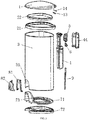
- a touch-control electronic trash bin in this embodiment comprises a lid 1, a lid torsion spring 13, pressing rings (including an outer pressing ring 21 and an inner pressing ring 22), a bin body 3, a connecting base plate 4, a speed reducer 5, a motor 51, a circuit board 6, an inner bottom pad 71, an outer bottom pad 72, and a touch device 8, wherein the lid 1 is hinged to the connecting base plate 4 via lid spindle holes 12 and connecting base plate spindle holes 41, the connecting base plate 4 is fixed to an outer side of an upper rear portion of the bin body 3, the lid torsion spring 13 is mounted at a hinge joint of the lid 1 and the connecting base plate 4, the inner bottom pad 71 and the outer bottom pad 72 are fixed to the bottom of the bin body 3, an open cavity 73 is from in front portions of the inner bottom pad 71 and the outer bottom pad 72, the bin body 3 is provided with a notch 31 corresponding to the open cavity 73, and an open space 85 is formed in a lower portion of
- the lid torsion spring 13 counteracts most of the weight of the lid 1, so that the lid can be opened with little power, the size and cost of the motor 51 are reduced, and the service life of a battery is prolonged.
- the connecting base plate 4, the speed reducer 5, the motor 51, the circuit board 6 and the battery are mounted on the outer side of the upper rear part of the bin body 3, so that the internal capacity of the bin body 3 is not affected; meanwhile, these components are located on a back side of the bin body 3, so that usage and a good appearance are guaranteed.
- the touch device 8 is mounted in the open space 85 in the lower portion of the front side of the trash bin and is integrated with the bin body 3, thereby being attractive and convenient to use.
- a lower portion of a back side of the lid 1 is provided with a sector gear 11 and the lid spindle holes 12.
- the sector gear 11 is engaged with an output gear 54 of the speed reducer.
- the connecting base plate spindle holes 41 are formed in the top of the connecting base plate 4.
- the center axis of the sector gear 11, the center axis of the lid spindle holes 12, and the center axis of the connecting base plate spindle holes 41 coincide.
- the lid 1 and the connecting base plate 4 are rotatably connected through a metal spindle 14 which is inserted into the lid spindle holes 12 and the connecting base plate spindle holes 41.
- the lid 1, the sector gear 11 and the lid spindle holes 12 are formed at a time by injection molding, so that the accuracy of the assembly dimension is guaranteed, and the cost is reduced.
- the output gear 54 of the speed reducer is directly engaged with the sector gear 11 on the lid 1, so that the rotating efficiency is improved, and the mechanical loss is reduced.
- the metal spindle is high in strength, thereby not being prone to deformation when stressed.
- the lid torsion spring 13 is disposed around the metal spindle 14 of the lid, and has an end acting on the connecting base plate 4 and an end acting on the lid 1, and the acting force from the lid torsion spring 13 is always upwards, so that most of the weight of the lid 1 is counteracted.
- the connecting base plate 4 is connected with a battery compartment 43 and is formed at a time by injection molding.
- the speed reducer 5, the motor 51 and the circuit board 6 are sequentially mounted, from top to bottom, on the connecting base plate 4 to form an assembly which is fixed to the outer side of the upper rear portion of the bin body 3 with screws, and are covered with a connecting base plate cover 44.
- the assembly can be independently assembled and adjusted, so that batch production is facilitated, and the labor cost is reduced.
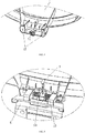
- the touch device 8 is composed of a touch support 81, a touch panel 82, a microswitch 83 and a touch panel torsion spring 84, wherein the touch support 81 is inserted into the notch 31 of the bin body, and has an upper end fixed to the inner bottom pad 71 and a lower end fixed to the outer bottom pad 72; the touch panel 82 is hinged to the touch support 81, and the touch panel torsion spring 84 is mounted at a hinge joint of the touch panel 82 and the touch support 81; and the microswitch 83 is mounted on the touch support 81, and a cam 821 is arranged on an inner side of the touch panel 82 and makes contact with the microswitch 83.
- the touch panel torsion spring 84 is used to realize restoration in such a manner: when a user presses the touch panel 82 with the foot, the touch panel 82 overcomes a spring force to rotate inwards by a small angle, so that the cam 821 arranged on the inner side of the touch panel moves away from a roller of the microswitch 83, and then the microswitch 83 is turned on to send a signal to a circuit; and when the user lifts the foot away from the touch panel 82, the touch panel 82 restores by means of the touch panel torsion spring 84, the cam 821 presses against the roller of the microswitch 83, and then the microswitch 83 is turned off.
- a microcomputer controller 61, a drive circuit 62, a brake circuit 63 and a photoelectric coupler 64 are arranged on the circuit board 6.
- a rotary shaft of the motor 51 is of a bidirectional output shaft structure, wherein a front output shaft is connected with a primary gear of the speed reducer, and a rear output shaft is connected with an optical grating 52 which is used for splitting an optical path of the photoelectric coupler 64.
- a 10th pin (input terminal) of the microcomputer controller 61 is electrically connected with the microswitch 83.
- the drive circuit 62 is composed of Q1-Q4 and R18-R21.
- the brake circuit 63 is composed of Ql, Q3, R19, R21, R21, D2 and D3.
- a control terminal of the drive circuit 62 and a control terminal of the brake circuit 63 are electrically connected with a 1st pin, a 12th pin, a 13th pin and a 14th pin of an output terminal of the microcomputer controller 61.
- An output signal of the photoelectric coupler 64 is electrically connected with a counter port (8th pin) of the microcomputer controller 61.
- the front output shaft of the motor 51 drives the primary gear of the speed reducer 5 to rotate, and then the speed reducer 5 drives the lid 1 to rotate; meanwhile, the rear output shaft of the motor 51 drives the optical grating 52 to rotate, a pulse signal output by the photoelectric coupler 64 is read by a counter of the microcomputer controller 61, data displayed on the counter indirectly reflects an opening angle of the lid 1, and a control program reads a current value on the counter to control the motor 51 to start or stop.
- a linear groove 74 is formed between the inner bottom pad and the outer bottom pad.
- a strip-shaped wire shield 9 is arranged on the back of the bin body 3.
- a microswitch connecting wire 831 reaches the back of the bin body 3 via the linear groove 74 between the inner bottom pad and the outer bottom pad, as well as the strip-shaped wire shield 9, so as to be electrically connected with the circuit board 6 on the connecting base plate 4.
- One end of the strip-shaped wire shield 9 is fixed to the outer bottom pad 72, and the other end of the strip-shaped wire shield 9 is fixed to the connecting base plate 4.
- the strip-shaped wire shield 9 is mainly used for covering the connecting wire 831.
- the pressing rings include the outer pressing ring 21 and the inner pressing ring 22, wherein the outer pressing ring 21 is disposed around an upper opening of the bin body 3, the inner pressing ring 22 is arranged on an inner edge of the outer pressing ring 21 in a sleeved manner, and the lid 1 is arranged over the outer pressing ring 21; and an open part of a trash bag is disposed around an inner edge of the inner pressing ring 22 and is then folded outwards, and a folded part 101 is firmly clamped in a gap between the inner pressing ring and the outer pressing ring.
- the microcomputer controller 61 has a port (10th pin) capable of fulfilling an awakening function and a timing function.
- the 10th pin of the port is electrically connected with the microswitch 83.
- the microswitch 83 When the microswitch 83 is triggered, the level of the 10th pin of the port becomes lower, so that the microcomputer controller is awakened from a standby sleep power-saving mode and then enters into a lid opening state; and after the lid is opened in place, if the microswitch is still triggered and the 10th pin is kept at a low level for over three seconds, the control program enters into a long-time opening procedure, so that the lid 1 is kept open all the time; or, if the microswitch keeps being triggered for less than three seconds, the lid 1 is opened and then automatically closes several seconds later, and the microcomputer controller enters into the standby sleep power-saving mode again to be prepared for the next work cycle.
- the touch-control electronic trash bin has the advantages of being reasonable in structural design, easy to assemble, low in cost and circuit power consumption, convenient to use, capable of keeping the lid open for a long time and higher in practicability, and having a few components.
Landscapes
- Engineering & Computer Science (AREA)
- Mechanical Engineering (AREA)
- Refuse Receptacles (AREA)
- Crushing And Pulverization Processes (AREA)
Applications Claiming Priority (2)
| Application Number | Priority Date | Filing Date | Title |
|---|---|---|---|
| CN201720069628.6U CN206456835U (zh) | 2017-01-20 | 2017-01-20 | 触控式电子垃圾桶 |
| PCT/CN2017/076096 WO2018133184A1 (zh) | 2017-01-20 | 2017-03-09 | 触控式电子垃圾桶 |
Publications (2)
| Publication Number | Publication Date |
|---|---|
| EP3539902A1 true EP3539902A1 (de) | 2019-09-18 |
| EP3539902A4 EP3539902A4 (de) | 2020-01-08 |
Family
ID=59696335
Family Applications (1)
| Application Number | Title | Priority Date | Filing Date |
|---|---|---|---|
| EP17892125.0A Withdrawn EP3539902A4 (de) | 2017-01-20 | 2017-03-09 | Berührungsgesteuerter elektronischer müllbehälter |
Country Status (6)
| Country | Link |
|---|---|
| US (1) | US11008163B2 (de) |
| EP (1) | EP3539902A4 (de) |
| JP (1) | JP3227977U (de) |
| CN (1) | CN206456835U (de) |
| AU (1) | AU2017394238A1 (de) |
| WO (1) | WO2018133184A1 (de) |
Cited By (1)
| Publication number | Priority date | Publication date | Assignee | Title |
|---|---|---|---|---|
| JP2022553439A (ja) * | 2019-12-31 | 2022-12-22 | 追▲べき▼科技(上海)有限公司 | スマートゴミ箱 |
Families Citing this family (16)
| Publication number | Priority date | Publication date | Assignee | Title |
|---|---|---|---|---|
| US9790025B2 (en) | 2012-03-09 | 2017-10-17 | Simplehuman, Llc | Trash can with clutch mechanism |
| US10279997B2 (en) | 2014-03-14 | 2019-05-07 | Simplehuman, Llc | Trash can assembly |
| CN206766831U (zh) * | 2017-05-08 | 2017-12-19 | 福建纳仕达电子股份有限公司 | 一种带转臂的感应翻盖垃圾桶 |
| CN107600837B (zh) * | 2017-09-04 | 2020-05-08 | 福建纳仕达电子股份有限公司 | 一种电子垃圾桶动作省电控制装置 |
| CN107512510A (zh) * | 2017-10-09 | 2017-12-26 | 安吉八塔机器人有限公司 | 智能垃圾桶 |
| CN108726045A (zh) * | 2018-06-14 | 2018-11-02 | 宁波大学 | 一种新型智能垃圾桶 |
| CN108906517A (zh) * | 2018-09-30 | 2018-11-30 | 无锡市华雁密封件轴承有限公司 | 一种浸胶甩干一体机 |
| CN110458372B (zh) * | 2019-08-21 | 2022-05-03 | 深圳市合隆智慧城市服务有限公司 | 一种基于云计算的智慧城市垃圾处理数据共享方法及系统 |
| US20220267089A1 (en) * | 2019-11-08 | 2022-08-25 | Nine Stars Group (USA) Inc. | Induction Actuated Trash Container with Actuation Arm |
| CN111115058B (zh) | 2020-01-22 | 2024-07-02 | 广州亿科智能家居科技有限公司 | 一种带有可转动插入栓的感应垃圾桶盖组件及其垃圾桶 |
| US20210262257A1 (en) * | 2020-02-20 | 2021-08-26 | James Stranger | Smart hatch actuation and locking systems for hatches windows and doors |
| CN213567856U (zh) * | 2020-05-19 | 2021-06-29 | 江门市锦隆高科实业有限公司 | 翻盖机构及垃圾桶 |
| USD1009652S1 (en) * | 2022-04-18 | 2024-01-02 | Eko Development Ltd. | Semi-round sensor can |
| USD1072412S1 (en) * | 2023-03-02 | 2025-04-22 | Simplehuman, Llc | Trash can |
| US12698153B2 (en) | 2023-03-03 | 2026-08-04 | Simplehuman, Llc | Receptacles with interior liner dispensers |
| US20240317174A1 (en) * | 2023-03-24 | 2024-09-26 | Andres Felipe Chavez Cortes | Device and System for Item Storage and Retrieval by Delivery Robots |
Family Cites Families (7)
| Publication number | Priority date | Publication date | Assignee | Title |
|---|---|---|---|---|
| CN2918290Y (zh) * | 2006-07-17 | 2007-07-04 | 林聪祐 | 具有夹固垃圾袋装置的垃圾桶 |
| US9054609B2 (en) * | 2010-09-10 | 2015-06-09 | Xin Wang | Container with touch control arrangement |
| CN202072198U (zh) * | 2011-05-24 | 2011-12-14 | 王昕� | 轻触式缓冲关盖电动垃圾桶 |
| US8678219B1 (en) * | 2012-12-13 | 2014-03-25 | Xin Wang | Lid operation arrangement for container |
| CN203450671U (zh) * | 2013-07-26 | 2014-02-26 | 杜朗 | 轻触式电动垃圾桶 |
| CN204078592U (zh) * | 2014-07-28 | 2015-01-07 | 高永锐 | 一种触屏式电动垃圾桶 |
| US9555963B2 (en) * | 2014-08-29 | 2017-01-31 | Thomas E. McConnell | System and apparatus for waste disposal and changing infant-toddler behavior |
-
2017
- 2017-01-20 CN CN201720069628.6U patent/CN206456835U/zh active Active
- 2017-03-09 AU AU2017394238A patent/AU2017394238A1/en not_active Abandoned
- 2017-03-09 JP JP2019600090U patent/JP3227977U/ja active Active
- 2017-03-09 US US16/079,084 patent/US11008163B2/en not_active Expired - Fee Related
- 2017-03-09 EP EP17892125.0A patent/EP3539902A4/de not_active Withdrawn
- 2017-03-09 WO PCT/CN2017/076096 patent/WO2018133184A1/zh not_active Ceased
Cited By (2)
| Publication number | Priority date | Publication date | Assignee | Title |
|---|---|---|---|---|
| JP2022553439A (ja) * | 2019-12-31 | 2022-12-22 | 追▲べき▼科技(上海)有限公司 | スマートゴミ箱 |
| US11753241B2 (en) | 2019-12-31 | 2023-09-12 | Dreame Technology (shanghai) Co., Ltd. | Intelligent garbage can |
Also Published As
| Publication number | Publication date |
|---|---|
| US11008163B2 (en) | 2021-05-18 |
| CN206456835U (zh) | 2017-09-01 |
| US20190055087A1 (en) | 2019-02-21 |
| WO2018133184A1 (zh) | 2018-07-26 |
| AU2017394238A1 (en) | 2019-06-20 |
| JP3227977U (ja) | 2020-10-01 |
| EP3539902A4 (de) | 2020-01-08 |
Similar Documents
| Publication | Publication Date | Title |
|---|---|---|
| AU2017394238A1 (en) | Touch control electronic waste bin | |
| US11338994B2 (en) | Induction actuation trash container with actuation arm | |
| US20220267089A1 (en) | Induction Actuated Trash Container with Actuation Arm | |
| WO2012000235A1 (zh) | 轻触式电动垃圾桶 | |
| CN208740847U (zh) | 一种智能马桶盖 | |
| CN219374133U (zh) | 无线充电式镜柜 | |
| CN211860495U (zh) | 一种耳机充电盒 | |
| CN211176924U (zh) | 一种带储物空间的集成灶头部 | |
| CN108692339A (zh) | 家用燃气灶智能控制旋钮 | |
| CN112031579A (zh) | 一种用于衣柜门的自动关闭装置 | |
| CN215248885U (zh) | 一种电梯按键无接触控制装置 | |
| CN112998433B (zh) | 一种智能防止文件损坏文件柜 | |
| CN110994882A (zh) | 一种户外用直线驱动器 | |
| CN209973393U (zh) | 一种感应式智能垃圾桶 | |
| CN217722898U (zh) | 一种智能化妆镜 | |
| CN210958032U (zh) | 一种户外用直线驱动器 | |
| CN222630175U (zh) | 一种电动式红外感应垃圾桶 | |
| CN217731522U (zh) | 一种智能垃圾桶 | |
| CN208312449U (zh) | 家用燃气灶智能控制旋钮 | |
| CN209780571U (zh) | 一种电动门窗推拉装置 | |
| CN222090789U (zh) | 一种可进行湿温度检测的雪茄盒 | |
| CN223416142U (zh) | 一种自动翻面盖和坐圈的分体式坐便器智能盖板 | |
| CN224177492U (zh) | 一种智能化可拆卸电池的开窗开门装置 | |
| CN214843407U (zh) | 一种计算机温湿度环境检测试验箱 | |
| CN219109288U (zh) | 智能马桶智能感应翻盖机构 |
Legal Events
| Date | Code | Title | Description |
|---|---|---|---|
| PUAI | Public reference made under article 153(3) epc to a published international application that has entered the european phase |
Free format text: ORIGINAL CODE: 0009012 |
|
| 17P | Request for examination filed |
Effective date: 20190611 |
|
| AK | Designated contracting states |
Kind code of ref document: A1 Designated state(s): AL AT BE BG CH CY CZ DE DK EE ES FI FR GB GR HR HU IE IS IT LI LT LU LV MC MK MT NL NO PL PT RO RS SE SI SK SM TR |
|
| AX | Request for extension of the european patent |
Extension state: BA ME |
|
| A4 | Supplementary search report drawn up and despatched |
Effective date: 20191210 |
|
| RIC1 | Information provided on ipc code assigned before grant |
Ipc: B65F 1/06 20060101ALI20191204BHEP Ipc: B65F 1/16 20060101AFI20191204BHEP |
|
| DAV | Request for validation of the european patent (deleted) | ||
| DAX | Request for extension of the european patent (deleted) | ||
| STAA | Information on the status of an ep patent application or granted ep patent |
Free format text: STATUS: THE APPLICATION IS DEEMED TO BE WITHDRAWN |
|
| 18D | Application deemed to be withdrawn |
Effective date: 20200721 |