EP3540125A1 - Pont en béton composite hybride et procédé d'assemblage - Google Patents
Pont en béton composite hybride et procédé d'assemblage Download PDFInfo
- Publication number
- EP3540125A1 EP3540125A1 EP19162378.4A EP19162378A EP3540125A1 EP 3540125 A1 EP3540125 A1 EP 3540125A1 EP 19162378 A EP19162378 A EP 19162378A EP 3540125 A1 EP3540125 A1 EP 3540125A1
- Authority
- EP
- European Patent Office
- Prior art keywords
- girder
- concrete
- girders
- top flanges
- hybrid composite
- Prior art date
- Legal status (The legal status is an assumption and is not a legal conclusion. Google has not performed a legal analysis and makes no representation as to the accuracy of the status listed.)
- Withdrawn
Links
- 239000002131 composite material Substances 0.000 title claims description 98
- 239000004567 concrete Substances 0.000 title claims description 88
- 238000000034 method Methods 0.000 title claims description 5
- 239000011150 reinforced concrete Substances 0.000 claims description 31
- 229920002430 Fibre-reinforced plastic Polymers 0.000 claims description 23
- 239000011151 fibre-reinforced plastic Substances 0.000 claims description 23
- 229910000831 Steel Inorganic materials 0.000 claims description 19
- 239000010959 steel Substances 0.000 claims description 19
- 239000007787 solid Substances 0.000 claims description 12
- 239000011440 grout Substances 0.000 claims description 10
- 239000000463 material Substances 0.000 claims description 10
- 238000010276 construction Methods 0.000 claims description 9
- 239000006260 foam Substances 0.000 claims description 6
- 238000005728 strengthening Methods 0.000 claims description 6
- 240000007182 Ochroma pyramidale Species 0.000 claims description 4
- 230000001154 acute effect Effects 0.000 claims description 3
- 230000002089 crippling effect Effects 0.000 claims description 3
- 239000011162 core material Substances 0.000 description 6
- 239000011178 precast concrete Substances 0.000 description 4
- 238000009415 formwork Methods 0.000 description 3
- 230000007246 mechanism Effects 0.000 description 3
- 230000001483 mobilizing effect Effects 0.000 description 2
- 239000010426 asphalt Substances 0.000 description 1
- 239000006261 foam material Substances 0.000 description 1
- 239000011521 glass Substances 0.000 description 1
- 239000011513 prestressed concrete Substances 0.000 description 1
- 230000003014 reinforcing effect Effects 0.000 description 1
- 239000000565 sealant Substances 0.000 description 1
Images





Classifications
-
- E—FIXED CONSTRUCTIONS
- E01—CONSTRUCTION OF ROADS, RAILWAYS, OR BRIDGES
- E01D—CONSTRUCTION OF BRIDGES, ELEVATED ROADWAYS OR VIADUCTS; ASSEMBLY OF BRIDGES
- E01D2/00—Bridges characterised by the cross-section of their bearing spanning structure
-
- E—FIXED CONSTRUCTIONS
- E04—BUILDING
- E04C—STRUCTURAL ELEMENTS; BUILDING MATERIALS
- E04C3/00—Structural elongated elements designed for load-supporting
- E04C3/02—Joists; Girders, trusses, or trusslike structures, e.g. prefabricated; Lintels; Transoms; Braces
- E04C3/28—Joists; Girders, trusses, or trusslike structures, e.g. prefabricated; Lintels; Transoms; Braces of materials not covered by groups E04C3/04 - E04C3/20
-
- E—FIXED CONSTRUCTIONS
- E04—BUILDING
- E04C—STRUCTURAL ELEMENTS; BUILDING MATERIALS
- E04C3/00—Structural elongated elements designed for load-supporting
- E04C3/02—Joists; Girders, trusses, or trusslike structures, e.g. prefabricated; Lintels; Transoms; Braces
- E04C3/29—Joists; Girders, trusses, or trusslike structures, e.g. prefabricated; Lintels; Transoms; Braces built-up from parts of different material, i.e. composite structures
- E04C3/291—Joists; Girders, trusses, or trusslike structures, e.g. prefabricated; Lintels; Transoms; Braces built-up from parts of different material, i.e. composite structures with apertured web
-
- E—FIXED CONSTRUCTIONS
- E01—CONSTRUCTION OF ROADS, RAILWAYS, OR BRIDGES
- E01D—CONSTRUCTION OF BRIDGES, ELEVATED ROADWAYS OR VIADUCTS; ASSEMBLY OF BRIDGES
- E01D19/00—Structural or constructional details of bridges
- E01D19/12—Grating or flooring for bridges; Fastening railway sleepers or tracks to bridges
- E01D19/125—Grating or flooring for bridges
-
- E—FIXED CONSTRUCTIONS
- E01—CONSTRUCTION OF ROADS, RAILWAYS, OR BRIDGES
- E01D—CONSTRUCTION OF BRIDGES, ELEVATED ROADWAYS OR VIADUCTS; ASSEMBLY OF BRIDGES
- E01D21/00—Methods or apparatus specially adapted for erecting or assembling bridges
-
- E—FIXED CONSTRUCTIONS
- E01—CONSTRUCTION OF ROADS, RAILWAYS, OR BRIDGES
- E01D—CONSTRUCTION OF BRIDGES, ELEVATED ROADWAYS OR VIADUCTS; ASSEMBLY OF BRIDGES
- E01D2101/00—Material constitution of bridges
- E01D2101/20—Concrete, stone or stone-like material
- E01D2101/24—Concrete
- E01D2101/26—Concrete reinforced
-
- E—FIXED CONSTRUCTIONS
- E01—CONSTRUCTION OF ROADS, RAILWAYS, OR BRIDGES
- E01D—CONSTRUCTION OF BRIDGES, ELEVATED ROADWAYS OR VIADUCTS; ASSEMBLY OF BRIDGES
- E01D2101/00—Material constitution of bridges
- E01D2101/40—Plastics
Definitions
- This invention relates in general to bridges having precast or Cast-In-Place (CIP) concrete deck panels.
- this invention relates to embodiments of improved girders for use in bridges having precast or CIP concrete decks and an improved system for assembling a bridge comprising the improved girders and precast or CIP concrete deck panels.
- Known bridges that are assembled using precast or CIP concrete deck panels typically use girders formed from steel, reinforced concrete, or pre-stressed concrete that are relatively heavy.
- a typical 40 ft bridge steel girder may weigh about 3,440 lbs
- a typical 40 ft concrete double-T girder may weigh about 40,120 lbs.
- to assemble one four-span, two-lane bridge with such steel or concrete girders requires multiple trucks to move the girders to a bridge site, and involves mobilizing large, expensive cranes with a high load capacity at the bridge site.
- an elongated girder for use in a bridge includes a girder body having a modified V-shaped cross section.
- the body includes longitudinally extending webs defining sides of the girder, a bottom flange extending between the webs, and top flanges extending outwardly from the webs.
- the girders 12 extend between seats 14 formed in conventional bridge abutments 16.
- a Cast-In-Place (CIP) concrete deck 18 is shown formed on the plurality of girders 12.
- the illustrated CIP concrete deck 18 includes a plurality of conventional reinforcing bars or rebar 20 formed therein. Paving material 22, such as asphalt is shown applied over the concrete deck 18.
- the bridge 10 may also be formed with a plurality of precast concrete deck panels P1, P2, and P3 (not shown in Fig. 1 , but see Figs. 9 through 16 ) rather than the CIP concrete deck 18.
- an interior of the girder 12 at the distal ends 11A and 11B of the girder body 11 may be filled with a material 24, such as concrete to strengthen the distal ends 11A and 11B of the girder body 11 to prevent crippling of the girder 12 at the bridge abutments 16.
- a plate (not shown) of solid composite material, such as, but not limited to FRP may be installed in the interior of the girder 12 at the distal ends 11A and 11B of the girder body 11, extend between the bottom flange 30 and the top flanges 32 and 34, and affixed to the webs 26 and 28 in a plane substantially perpendicular to a longitudinal axis of the girder 12.
- the plate (not shown) may have solid construction or may have one or more openings therethrough.
- a truss-type brace (not shown) may be installed in the interior of the girder 12 at the distal ends 11A and 11B of the girder body 11 between the webs 26 and 28.
- girders In conventional bridge construction for two-lane bridges, approximately four girders are placed between bridge abutments. The bridge deck is then supported on the bridge girders. The girders are typically placed about 6 ft to 7 ft apart. Concrete deck panels, such as the panels P1, P2, and P3, are then positioned perpendicularly to the girders and attached thereto. Alternatively, a concrete deck may be cast in place over the girders. A length of the deck members is typically equal to a width of the bridge.
- the girders For a single-span two-lane bridge, the girders have a length about equal to the length of the bridge to be constructed.
- the precast reinforced concrete deck panels may have a length equal to a width of the bridge such as about 30 ft, or half the width of the bridge such as about 15ft, and a width within the range of about 4 ft to about 8 ft.
- the girders typically have a length equal to a length of each span.
- CIP decks, such as the concrete deck 18, may be placed over temporary, i.e., removable, or stay-in-place formwork spanning between and/or over the girders 12.
- the hybrid composite girder 12 has an elongated girder body 11 defining first and second distal ends 11A and 11B.
- the girder body 11 has a modified V-shape when viewed in cross-section.
- the girder body 11 further includes longitudinally extending webs 26 and 28 defining sides of the girder 12, a bottom flange 30 extending between the webs 26 and 28, and top flanges 32 and 34 extending outwardly from the webs 26 and 28, respectively.
- the top flanges 32 and 34 are substantially parallel with the bottom flange 30.
- a plurality of apertures 36 are formed through each of the top flanges 32 and 34.
- the bottom flange 30 and the top flanges 32 and 34 are preferably formed from solid composite fiber reinforced polymer (FRP) material.
- the webs 26 and 28 preferably have a sandwich type construction and are formed from a layer of lightweight core material 29 (shown schematically in Fig. 3 ) such as a foam material, positioned between two layers of solid composite material, such as, but not limited to FRP, skins.
- the core material 29 may be formed from any desired material, including, but not limited to foam and balsa.
- the core material 29 may have any desired thickness that will vary based on a length of the span of the bridge in which the hybrid composite girders 12 will be used.
- the core material 29 may be thicker in a central portion of the hybrid composite girder 12 and thinner towards the distal ends 11A and 11B of the girder body 11.
- the hybrid composite girder 12 may have no core material 29 at the distal ends 11A and 11B of the girder body 11 but have core material 29 over the interior portions of the span of the girder 12.
- the thicknesses of the webs 26 and 28 and the bottom flange 30 will preferably vary in a stepwise manner along the girder span.
- the thickness of the bottom flange 30 increases mostly stepwise towards mid-span of the girder and the thickness of the webs 26 and 28 increase stepwise towards the ends of the girder. This is illustrated using typical dimensions for an exemplary 42 ft girder in Fig. 2 .
- Fig. 2 illustrates one example of the hybrid composite girder 12 having a length of 42.0 ft.
- the top flanges 32 and 34 are formed from glass FRP and have a thickness of about 1.0 in, but this thickness may vary based on a span length of the bridge, and may further vary based on the type of bridge deck, i.e., a deck formed from reinforced concrete deck panels P1, P2, and P3, or the CIP deck 18.
- the top flanges 32 and 34 are preferably formed to have a bolt bearing strength sufficient to achieve composite action between the FRP top flanges 32 and 34 and the concrete deck, i.e., the reinforced concrete deck panels P1, P2, and P3, or the CIP deck 18.
- the top flanges 32 and 34 may be formed to have a bolt bearing strength that is at least equal to a shear strength of the steel bolts. Additionally, the top flanges 32 and 34 are preferably formed to further have a combined bolt bearing strength that is at least equal to a compressive strength of the plurality of reinforced concrete deck panels P1, P2, and P3.
- the 42.0 ft hybrid composite girder 12 will preferably have a camber D1 when used with bridges built on sections of roadway with a constant grade, and when not loaded.
- Sections of the hybrid composite girder 12, indicated by the letters A through D in Fig. 2 will preferably have different thicknesses for the webs 26 and 28 and the bottom flange 30.
- One nonlimiting example of a thickness for the webs 26 and 28 and the bottom flange 30 in each of the sections A through D of the exemplary 42.0 ft girder is shown in Table 1.
- these thicknesses may vary based on a span length of the bridge, and may further vary based on the type of bridge deck, i.e., a deck formed from reinforced concrete deck panels P1, P2, and P3, or the CIP deck 18.
- Table 1 COMPOSITE GIRDER DIMENSIONS GIRDER SECTION LENGTH WEB THICKNESS BOTTOM FLANGE THICKNESS A about 6.0 ft about 1.80 about 0.50 B about 5.0 ft about 1.80 about 0.70 C about 5.0 ft about 1.75 about 0.75 D about 5.0 ft about 1.70 about 0.75
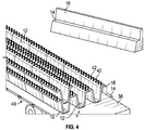
- Fig. 4 illustrates the bed 38 of a truck 40.
- a plurality of the hybrid composite girders 12 are stacked and nested on the truck bed 38.
- the hybrid composite girders 12 are positioned near two bridge abutments 16 upon which the hybrid composite girders 12 will be mounted.
- the top flanges 32 and 34 may include a plurality of outwardly extending (upwardly extending when viewing Fig. 4 ) steel shear connectors 42, such as steel bolts, each mounted in an aperture 36 and each having a length of about 4.0 in above an upper surface of the top flanges 32 and 34 (the upwardly facing surfaces when viewing Fig. 4 ).
- top flanges 32 and 23 of the elongated girders 12 may be smooth or intentionally roughened to promote shear transfer between the girder 12 and the concrete deck panels P1, P2, and P3 or the CIP deck 18 formed thereon as described below. Additionally, a combination of the smooth surface or the roughened surface and a clamping force from the steel bolts 42 promotes shear transfer between each girder 12 and the concrete deck panels P1, P2, and P3.
- the hybrid composite girder 80 has the modified V-shape when viewed in cross-section and includes longitudinally extending webs 82 and 84 defining sides of the girder 80, a bottom flange 86 extending between the webs 82 and 84, and top flanges 88 and 90 extending outwardly from the webs 82 and 84, respectively.
- the top flanges 88 and 90 are substantially parallel with the bottom flange 86.
- a plurality of apertures (not shown in Figs 17 and 18 , but substantially similar to the apertures 36 shown in Fig. 3 ) may be formed through each of the top flanges 88 and 90.
- a top surface 92 of the top flanges 88 and 90 (the upwardly facing surface when viewing Figs. 17 and 18 ) has a corrugated surface contour.
- This corrugated surface 92 also promotes shear transfer between the girder 80 and the concrete deck panels P1, P2, and P3 or the CIP deck 18 formed thereon as described below. Additionally, a combination of the corrugated surface 92 and a clamping force from the steel bolts 42 promotes shear transfer between each girder 12 and the concrete deck panels P1, P2, and P3.
- the illustrated corrugations have a depth D2 of about 0.25 inches.
- the depth D2 of the corrugations may vary based on factors including, but not limited to, the size of the hybrid composite girder 80 and a desired value of shear transfer between each girder 80 and the concrete deck panels P1, P2, and P3.
- each hybrid composite hybrid composite girder 12 has a significantly lower weight than a conventional girder of the same length.
- a 40.0 ft hybrid composite hybrid composite girder 12 has a weight of about 1,323 lbs.
- a 40.0 ft conventional steel I-beam girder 44 weighs about 3,440 lbs, and a 40.0 ft conventional reinforced concrete double-T girder 46 (see Fig. 6 ) weighs about 40,120 lbs.
- Table 2 BRIDGE DESIGN PARAMETERS PARAMETER COMPOSITE GIRDER 12 I-BEAM GIRDER 44 DOUBLE-T GIRDER 46 SPAN (FT) 40 40 40 40 TOTAL WIDTH (FT) 30 30 32 NO. OF GIRDERS 4 4 4 GIRDER SPACING (FT) 7.5 7.5 8 GIRDER WEIGHT (LBS) 1,323 3,440 40,120
- each of the webs 26 and 28 are formed at an acute angle ⁇ from a line L1 that extends perpendicularly (vertically when viewing Fig. 3 ) from the bottom flange 30.
- the angle ⁇ will vary based on factors including, but not limited to, the size of the hybrid composite girder 12.
- each hybrid composite girder 12 is formed such that inside surfaces of the webs 26 and 28 and the bottom flange 30 are smooth such that they have substantially no obstructions extending outwardly therefrom.
- the significantly reduced weight of the hybrid composite girders 12 relative to the conventional steel I-beam girder 44 and the conventional reinforced concrete double-T girder 46 as shown in Table 2, and the angle ⁇ from the vertical line L1 at which the webs 26 and 28 are formed (which thus defines the modified V-shaped cross-section of the hybrid composite girder 12) that allows for nesting transportation costs may be significantly reduced.
- 15 of the 40.0 ft span hybrid composite girders 12 may be nested and carried on one flatbed truck 40.
- the same 15 of the 40.0 ft span hybrid composite girders 12 may be nested and carried within one standard shipping container 48.
- the illustrated 15 hybrid composite girders 12 are enough to assemble three to four bridges and collectively weigh only about 19,845 lbs.
- 15 of the 40.0 ft span steel I-beam girders 44 weigh about 51,600 lbs and will require at least two trucks to move.
- 15 of the 40.0 ft span reinforced concrete double-T girders 46 weigh about 601,800 lbs and will require at least 15 trucks to move, i.e., each 40.0 ft span reinforced concrete double-T girder 46 requires one truck to move.
- the efficiencies realized in moving a plurality of a 70.0 ft span embodiment of the hybrid composite girders 50 is even greater.
- up to 16 of the 70.0 ft span hybrid composite girders 50 may be nested and carried on one flatbed truck 40, although for illustrative purposes, only 12 of the 70.0 ft span hybrid composite girders 50 are shown nested and carried on the flatbed truck 40.
- the 16 hybrid composite girders 50 are enough to assemble four bridges and collectively weigh only about 42,496 lbs, or about 2,656 lbs each.
- 16 of a 70.0 ft embodiment of the steel I-beam girders 44 weigh about 151,200 lbs, or about 9,450 lbs each, and will require at least four trucks to move.
- a 70 ft span embodiment of the concrete double-T girder 46 weighs about 70,210 lbs.
- each 70 ft span embodiment of the concrete double-T girder 46 will require one truck to move.
- the bridge 10 may be assembled in minimal time, such as in one day or less, and with minimal, economical, and readily available equipment.
- a bridge 10 comprising a plurality of the hybrid composite girders 12 according to the invention may be assembled with one locally available conventional crane truck or one locally available conventional deck crane.
- any suitable conventional crane truck and any suitable conventional deck crane may be used.
- such conventional crane trucks and conventional deck cranes are typically commercially available from an equipment rental firm, thus allowing a required crane truck and/or a required deck crane to be rented only for the short duration of the bridge assembly, such as one day, eliminating the cost of mobilizing and operating a large crane.
- top flanges 32 and 34 may be braced together with X-bracing in a substantially horizontal plane.
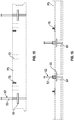
- Fig. 9 is a side elevational view, in cross-section, of an embodiment of the bridge 10 assembled with a plurality of the hybrid composite girders 12 and precast, reinforced concrete deck panels P1, P2, and P3 mounted to the hybrid composite girders 12.
- a deck panel P1 is positioned at one distal end of the bridge span (the left end when viewing Fig. 9 ).
- a deck panel P2 is similar to the deck panel P1, such as a mirror image thereof, and is positioned at an opposite distal end of the bridge span (the right end when viewing Fig. 9 ).
- Deck panels P3 are positioned between the deck panels P1 and P2.
- Each of the deck panels P1, P2, and P3 may include one or more conventional leveling mechanisms 52 to align and level the individual deck panels P1, P2, and P3.
- adjacent deck panels P2 may be separated by a foam backing rod 58.
- Sections of rebar 60 and 62 are shown extending outward of the deck panels P3.
- the deck panels P3 may further be attached to the top flanges 32 and 34 by a plurality of threaded fasteners 54 that extend through the top flanges 32 and 34.
- a layer of caulking 56 such as a foam haunch sealant may be applied to the upwardly facing surfaces of the top flanges 32 and 34 prior to positioning the reinforced concrete deck panels P1, P2, and P3 thereon.
- the precast concrete deck panels P1, P2, and P3 further include pairs of parallel channels 64 in a lower surface thereof.
- the deck panels P1, P2, and P3 may be positioned on the hybrid composite girders 12 such that the shear connectors 42 on each of the top flanges 32 and 34 are positioned inside one of the channels 64.
- Each channel 64 may include one or more access bore 66 extending from the channels 34 to an upper surface of the deck panels P1, P2, and P3.
- each deck panel P1, P2, and P3 may include a plurality of conventional leveling mechanisms 52 to align and level the individual deck panels P1, P2, and P3.
- the illustrated leveling mechanisms 52 include a leveling bolt 53 and a threaded plate 55.
- concrete grout (not shown) may be applied through the access bores 72 to fill the channels 64 around the steel bolts 42 to further secure the deck panels P1, P2, and P3 to the hybrid composite girders 12 when the grout is cured.
- the deck panel P3 includes a lifting point 70.
- Each of the deck panels P1 and P2 may also have the lifting point 70.
- the concrete deck panels P1, P2, and P3 are attached to the girders 12, no portion of the concrete deck panels P1, P2, and P3 extend below the top flanges 32 and 34. Additionally, the concrete grout within the parallel channels 64 and about the shear connectors 42 therein, further secure the concrete deck panels P1, P2, and P3 to the elongated girders 12, such that the bridge system 12 is capable of supporting a weight of the concrete deck panels P1, P2, and P3 prior to the concrete grout within the parallel channels 64 being fully cured.
- a CIP deck may be formed over the hybrid composite girders 12.
- the CIP deck such as the CIP concrete deck 18 shown in Fig. 1 , may be cast over conventional removable or stay-in-place formwork (not shown) spanning between the hybrid composite girders 12.
- hybrid composite girders 12, shear connectors 42, reinforced (CIP) concrete deck 18 (or alternatively, the precast concrete deck panels P1, P2, and P3) according to this invention define a hybrid composite concrete bridge system, such as shown at 10 in Fig. 1 , that can be assembled with lower logistics, faster, and with a lower cost relative to known bridges.
Landscapes
- Engineering & Computer Science (AREA)
- Architecture (AREA)
- Civil Engineering (AREA)
- Structural Engineering (AREA)
- Chemical & Material Sciences (AREA)
- Composite Materials (AREA)
- Bridges Or Land Bridges (AREA)
Applications Claiming Priority (1)
| Application Number | Priority Date | Filing Date | Title |
|---|---|---|---|
| US201862641562P | 2018-03-12 | 2018-03-12 |
Publications (1)
| Publication Number | Publication Date |
|---|---|
| EP3540125A1 true EP3540125A1 (fr) | 2019-09-18 |
Family
ID=65817757
Family Applications (1)
| Application Number | Title | Priority Date | Filing Date |
|---|---|---|---|
| EP19162378.4A Withdrawn EP3540125A1 (fr) | 2018-03-12 | 2019-03-12 | Pont en béton composite hybride et procédé d'assemblage |
Country Status (2)
| Country | Link |
|---|---|
| US (1) | US10494779B2 (fr) |
| EP (1) | EP3540125A1 (fr) |
Families Citing this family (13)
| Publication number | Priority date | Publication date | Assignee | Title |
|---|---|---|---|---|
| US10895047B2 (en) | 2016-11-16 | 2021-01-19 | Valmont Industries, Inc. | Prefabricated, prestressed bridge module |
| CN108252210A (zh) * | 2018-04-09 | 2018-07-06 | 长沙理工大学 | 节段现浇uhpc桥梁梁段接头及其施工方法 |
| US10704215B2 (en) * | 2018-04-11 | 2020-07-07 | Vellaisamy THAVAMANI PANDI | System for construction of composite U shaped reinforced girders bridge deck and methods thereof |
| US10718094B1 (en) * | 2019-02-12 | 2020-07-21 | Valmont Industries, Inc. | Tub girders and related manufacturing methods |
| CN111705673A (zh) * | 2020-06-29 | 2020-09-25 | 交通运输部公路科学研究所 | 一种高聚物钢桥面铺装结构 |
| CN112746706A (zh) * | 2021-01-04 | 2021-05-04 | 山东斯福特实业有限公司 | 一种连续frp复合纤维桁架抗剪切连接件 |
| CN112695617B (zh) * | 2021-02-04 | 2024-11-29 | 重庆交通大学 | 用于装配式钢混组合梁的剪力联结结构 |
| US12270201B2 (en) | 2021-05-20 | 2025-04-08 | Pavestone, LLC | Decorative block with load-bearing area |
| WO2022266089A1 (fr) | 2021-06-18 | 2022-12-22 | Chaudhari Ashok | Système de plancher et de plancher en béton destiné à rester en place sans armature en acier réalisée à partir de pales d'éolienne recyclées |
| CN114645513B (zh) * | 2022-02-23 | 2023-05-16 | 中国一冶集团有限公司 | 一种预应力混凝土箱梁腹板凿毛机 |
| CN115718942B (zh) * | 2022-11-21 | 2025-12-16 | 武汉理工大学 | 基于剪力钉增强的组合销连接件抗剪承载力确定方法 |
| JP2024087953A (ja) * | 2022-12-20 | 2024-07-02 | 株式会社オーイケ | 構造体ブロックおよび構造体ブロックを用いた構造物の施工方法 |
| JP2024101514A (ja) * | 2023-01-17 | 2024-07-29 | 株式会社オーイケ | 床板ブロックおよび橋梁 |
Citations (2)
| Publication number | Priority date | Publication date | Assignee | Title |
|---|---|---|---|---|
| US6081955A (en) * | 1996-09-30 | 2000-07-04 | Martin Marietta Materials, Inc. | Modular polymer matrix composite support structure and methods of constructing same |
| WO2009131284A1 (fr) * | 2008-04-21 | 2009-10-29 | Woo Kyoung Construction Co., Ltd. | Procédé de construction de poutrelle en u composite en acier à ouverture |
Family Cites Families (12)
| Publication number | Priority date | Publication date | Assignee | Title |
|---|---|---|---|---|
| US4229497A (en) * | 1977-11-03 | 1980-10-21 | Maso-Therm Corporation | Composite module with reinforced shell |
| US4129917A (en) * | 1978-03-27 | 1978-12-19 | Eugene W. Sivachenko | Bridge structure |
| US4912764A (en) * | 1985-08-28 | 1990-03-27 | American Telephone And Telegraph Company, At&T Bell Laboratories | Digital speech coder with different excitation types |
| US5967764A (en) * | 1997-08-08 | 1999-10-19 | Bosch Automotive Systems Corporation | Axial fan with self-cooled motor |
| US5966764A (en) * | 1998-07-02 | 1999-10-19 | Vodicka; Dennis A. | Roll beam girder system for bridges |
| US7013520B1 (en) * | 2002-05-24 | 2006-03-21 | Snead Edwin Desteiguer | Method for positioning a pile cap underneath an existing elevated bridge assembly |
| US7627921B2 (en) * | 2005-04-15 | 2009-12-08 | Board Of Regents Of University Of Nebraska | Girder system employing bent steel plating |
| US7861346B2 (en) * | 2005-06-30 | 2011-01-04 | Ail International Inc. | Corrugated metal plate bridge with composite concrete structure |
| KR20080107085A (ko) * | 2007-06-05 | 2008-12-10 | 삼성물산 주식회사 | 교량의 거더 설치공법 및 이에 사용되는 거더 인양크레인,임시거더, 거더 운반용 차량, 거더 |
| US20130061406A1 (en) * | 2011-09-14 | 2013-03-14 | Allied Steel | Modular Bridge |
| US8671490B1 (en) * | 2013-03-06 | 2014-03-18 | Mark Carney | Bridge span replacement system |
| US9915045B1 (en) * | 2016-11-08 | 2018-03-13 | The Florida International University Board Of Trustees | Folded steel plate bridge system |
-
2019
- 2019-03-12 US US16/299,825 patent/US10494779B2/en active Active
- 2019-03-12 EP EP19162378.4A patent/EP3540125A1/fr not_active Withdrawn
Patent Citations (2)
| Publication number | Priority date | Publication date | Assignee | Title |
|---|---|---|---|---|
| US6081955A (en) * | 1996-09-30 | 2000-07-04 | Martin Marietta Materials, Inc. | Modular polymer matrix composite support structure and methods of constructing same |
| WO2009131284A1 (fr) * | 2008-04-21 | 2009-10-29 | Woo Kyoung Construction Co., Ltd. | Procédé de construction de poutrelle en u composite en acier à ouverture |
Also Published As
| Publication number | Publication date |
|---|---|
| US20190276994A1 (en) | 2019-09-12 |
| US10494779B2 (en) | 2019-12-03 |
Similar Documents
| Publication | Publication Date | Title |
|---|---|---|
| US10494779B2 (en) | Hybrid composite concrete bridge and method of assembling | |
| US4300320A (en) | Bridge section composite and method of forming same | |
| US7461427B2 (en) | Bridge construction system and method | |
| JP3908642B2 (ja) | 合成パネル構造およびパネル橋梁構造ならびに連続合成桁橋の施工方法 | |
| US20100071141A1 (en) | Variable length beam | |
| US20020010973A1 (en) | Modular polymer matrix composite support structure and methods of constructing same | |
| US5471694A (en) | Prefabricated bridge with prestressed elements | |
| JP2004526074A (ja) | 橋床パネルの製造方法およびその使用法 | |
| EP4479593A1 (fr) | Tablier composite en rcc et superstructure de pont à poutres à âme ouverte en acier à membrure inférieure parabolique précontrainte et suspendue | |
| CA2880440A1 (fr) | Articulations entre elements en beton premoule | |
| JP2007016594A (ja) | 合成パネル構造およびパネル橋梁構造ならびに連続合成桁橋の施工方法 | |
| US5119731A (en) | Station on a railway or other line, situated on a viaduct | |
| JP4585614B1 (ja) | 合成鋼床版橋の施工方法、並びにリブ付き鋼床版、及び合成鋼床版橋 | |
| CN115961567A (zh) | 可调高的装配式uhpc桥面板轻型组合梁及桥面板调高方法 | |
| JPH04228710A (ja) | 橋梁用道路スラブ | |
| CN119392591A (zh) | 一种基于钢和混凝土的组合结构桥梁体系及施工方法 | |
| CN119491444A (zh) | 一种基于钢和混凝土的组合结构桥梁的墩顶连接结构及施工方法 | |
| AU2009204645A1 (en) | Precast concrete panel | |
| JP2025161167A (ja) | 床版架設方法 | |
| JP5029271B2 (ja) | 連続i桁橋およびその中間支点近傍のi桁の構造 | |
| JP2024151537A (ja) | 橋梁及びその構築方法 | |
| CN223240529U (zh) | 一种用于钢和混凝土组合梁的梁间连接结构 | |
| CN114250688A (zh) | 一种钢混组合梁及钢混组合梁的施工方法 | |
| CN223255829U (zh) | 一种用于钢和混凝土组合梁的梁间连接结构 | |
| CN223269074U (zh) | 一种用于钢和混凝土组合梁的梁间连接结构 |
Legal Events
| Date | Code | Title | Description |
|---|---|---|---|
| PUAI | Public reference made under article 153(3) epc to a published international application that has entered the european phase |
Free format text: ORIGINAL CODE: 0009012 |
|
| STAA | Information on the status of an ep patent application or granted ep patent |
Free format text: STATUS: THE APPLICATION HAS BEEN PUBLISHED |
|
| AK | Designated contracting states |
Kind code of ref document: A1 Designated state(s): AL AT BE BG CH CY CZ DE DK EE ES FI FR GB GR HR HU IE IS IT LI LT LU LV MC MK MT NL NO PL PT RO RS SE SI SK SM TR |
|
| AX | Request for extension of the european patent |
Extension state: BA ME |
|
| STAA | Information on the status of an ep patent application or granted ep patent |
Free format text: STATUS: REQUEST FOR EXAMINATION WAS MADE |
|
| 17P | Request for examination filed |
Effective date: 20191217 |
|
| RBV | Designated contracting states (corrected) |
Designated state(s): AL AT BE BG CH CY CZ DE DK EE ES FI FR GB GR HR HU IE IS IT LI LT LU LV MC MK MT NL NO PL PT RO RS SE SI SK SM TR |
|
| STAA | Information on the status of an ep patent application or granted ep patent |
Free format text: STATUS: EXAMINATION IS IN PROGRESS |
|
| 17Q | First examination report despatched |
Effective date: 20200729 |
|
| GRAP | Despatch of communication of intention to grant a patent |
Free format text: ORIGINAL CODE: EPIDOSNIGR1 |
|
| STAA | Information on the status of an ep patent application or granted ep patent |
Free format text: STATUS: GRANT OF PATENT IS INTENDED |
|
| INTG | Intention to grant announced |
Effective date: 20201113 |
|
| STAA | Information on the status of an ep patent application or granted ep patent |
Free format text: STATUS: THE APPLICATION IS DEEMED TO BE WITHDRAWN |
|
| 18D | Application deemed to be withdrawn |
Effective date: 20210324 |