EP3540173B1 - Geformte schneideelemente für erdbohrwerkzeuge, erdbohrwerkzeuge mit solchen schneideelementen und zugehörige verfahren - Google Patents
Geformte schneideelemente für erdbohrwerkzeuge, erdbohrwerkzeuge mit solchen schneideelementen und zugehörige verfahren Download PDFInfo
- Publication number
- EP3540173B1 EP3540173B1 EP19171698.4A EP19171698A EP3540173B1 EP 3540173 B1 EP3540173 B1 EP 3540173B1 EP 19171698 A EP19171698 A EP 19171698A EP 3540173 B1 EP3540173 B1 EP 3540173B1
- Authority
- EP
- European Patent Office
- Prior art keywords
- cutting
- polycrystalline diamond
- volume
- substrate base
- lateral side
- Prior art date
- Legal status (The legal status is an assumption and is not a legal conclusion. Google has not performed a legal analysis and makes no representation as to the accuracy of the status listed.)
- Active
Links
Images




Classifications
-
- E—FIXED CONSTRUCTIONS
- E21—EARTH OR ROCK DRILLING; MINING
- E21B—EARTH OR ROCK DRILLING; OBTAINING OIL, GAS, WATER, SOLUBLE OR MELTABLE MATERIALS OR A SLURRY OF MINERALS FROM WELLS
- E21B10/00—Drill bits
- E21B10/46—Drill bits characterised by wear resisting parts, e.g. diamond inserts
- E21B10/56—Button-type inserts
- E21B10/567—Button-type inserts with preformed cutting elements mounted on a distinct support, e.g. polycrystalline inserts
- E21B10/5673—Button-type inserts with preformed cutting elements mounted on a distinct support, e.g. polycrystalline inserts having a non planar or non circular cutting face
-
- B—PERFORMING OPERATIONS; TRANSPORTING
- B24—GRINDING; POLISHING
- B24D—TOOLS FOR GRINDING, BUFFING OR SHARPENING
- B24D18/00—Manufacture of grinding tools or other grinding devices, e.g. wheels, not otherwise provided for
-
- B—PERFORMING OPERATIONS; TRANSPORTING
- B24—GRINDING; POLISHING
- B24D—TOOLS FOR GRINDING, BUFFING OR SHARPENING
- B24D99/00—Subject matter not provided for in other groups of this subclass
- B24D99/005—Segments of abrasive wheels
-
- C—CHEMISTRY; METALLURGY
- C22—METALLURGY; FERROUS OR NON-FERROUS ALLOYS; TREATMENT OF ALLOYS OR NON-FERROUS METALS
- C22C—ALLOYS
- C22C29/00—Alloys based on carbides, oxides, nitrides, borides, or silicides, e.g. cermets, or other metal compounds, e.g. oxynitrides, sulfides
- C22C29/02—Alloys based on carbides, oxides, nitrides, borides, or silicides, e.g. cermets, or other metal compounds, e.g. oxynitrides, sulfides based on carbides or carbonitrides
- C22C29/06—Alloys based on carbides, oxides, nitrides, borides, or silicides, e.g. cermets, or other metal compounds, e.g. oxynitrides, sulfides based on carbides or carbonitrides based on carbides, but not containing other metal compounds
- C22C29/08—Alloys based on carbides, oxides, nitrides, borides, or silicides, e.g. cermets, or other metal compounds, e.g. oxynitrides, sulfides based on carbides or carbonitrides based on carbides, but not containing other metal compounds based on tungsten carbide
-
- E—FIXED CONSTRUCTIONS
- E21—EARTH OR ROCK DRILLING; MINING
- E21B—EARTH OR ROCK DRILLING; OBTAINING OIL, GAS, WATER, SOLUBLE OR MELTABLE MATERIALS OR A SLURRY OF MINERALS FROM WELLS
- E21B10/00—Drill bits
- E21B10/46—Drill bits characterised by wear resisting parts, e.g. diamond inserts
- E21B10/50—Drill bits characterised by wear resisting parts, e.g. diamond inserts the bit being of roller type
- E21B10/52—Drill bits characterised by wear resisting parts, e.g. diamond inserts the bit being of roller type with chisel- or button-type inserts
Definitions
- Embodiments of the present invention relate generally to cutting elements that include a table of superabrasive material (e.g., polycrystalline diamond or cubic boron nitride) formed on a substrate, to earth-boring tools including such cutting elements, and to methods of forming and using such cutting elements and earth-boring tools.
- a table of superabrasive material e.g., polycrystalline diamond or cubic boron nitride
- GB 2 324 553 A discloses a cutting element according to the preamble of independent claim 1.
- Earth-boring tools are commonly used for forming (e.g., drilling and reaming) bore holes or wells (hereinafter “wellbores”) in earth formations.
- Earth-boring tools include, for example, rotary drill bits, core bits, eccentric bits, bicenter bits, reamers, underreamers, and mills.
- Different types of earth-boring rotary drill bits are known in the art including, for example, fixed-cutter bits (which are often referred to in the art as “drag” bits), rolling-cutter bits (which are often referred to in the art as “rock” bits), diamond-impregnated bits, and hybrid bits (which may include, for example, both fixed cutters and rolling cutters).
- the drill bit is rotated and advanced into the subterranean formation. As the drill bit rotates, the cutters or abrasive structures thereof cut, crush, shear, and/or abrade away the formation material to form the wellbore.
- the drill bit is coupled, either directly or indirectly, to an end of what is referred to in the art as a "drill string,” which comprises a series of elongated tubular segments connected end-to-end that extends into the wellbore from the surface of the formation.
- a drill string which comprises a series of elongated tubular segments connected end-to-end that extends into the wellbore from the surface of the formation.
- various tools and components, including the drill bit may be coupled together at the distal end of the drill string at the bottom of the wellbore being drilled.
- This assembly of tools and components is referred to in the art as a “bottom hole assembly” (BHA).
- the drill bit may be rotated within the wellbore by rotating the drill string from the surface of the formation, or the drill bit may be rotated by coupling the drill bit to a downhole motor, which is also coupled to the drill string and disposed proximate the bottom of the wellbore.
- the downhole motor may comprise, for example, a hydraulic Moineau-type motor having a shaft, to which the drill bit is attached, that may be caused to rotate by pumping fluid (e.g., drilling mud or fluid) from the surface of the formation down through the center of the drill string, through the hydraulic motor, out from nozzles in the drill bit, and back up to the surface of the formation through the annular space between the outer surface of the drill string and the exposed surface of the formation within the wellbore.
- fluid e.g., drilling mud or fluid
- Rolling-cutter drill bits typically include three roller cones attached on supporting bit legs that extend from a bit body, which may be formed from, for example, three bit head sections that are welded together to form the bit body. Each bit leg may depend from one bit head section. Each roller cone is configured to spin or rotate on a bearing shaft that extends from a bit leg in a radially inward and downward direction from the bit leg.
- the cones are typically formed from steel, but they also may be formed from a particle-matrix composite material (e.g., a cermet composite such as cemented tungsten carbide). Cutting teeth for cutting rock and other earth formations may be machined or otherwise formed in or on the outer surfaces of each cone.
- receptacles are formed in outer surfaces of each cone, and inserts formed of hard, wear resistant material are secured within the receptacles to form the cutting elements of the cones.
- the roller cones roll and slide across the surface of the formation, which causes the cutting elements to crush and scrape away the underlying formation.
- Fixed-cutter drill bits typically include a plurality of cutting elements that are attached to a face of bit body.
- the bit body may include a plurality of wings or blades, which define fluid courses between the blades.
- the cutting elements may be secured to the bit body within pockets formed in outer surfaces of the blades.
- the cutting elements are attached to the bit body in a fixed manner, such that the cutting elements do not move relative to the bit body during drilling.
- the bit body may be formed from steel or a particle-matrix composite material (e.g., cobalt-cemented tungsten carbide).
- the bit body may be attached to a metal alloy (e.g., steel) shank having a threaded end that may be used to attach the bit body and the shank to a drill string.
- a metal alloy e.g., steel
- the cutting elements scrape across the surface of the formation and shear away the underlying formation.
- Impregnated diamond rotary drill bits may be used for drilling hard or abrasive rock formations such as sandstones.
- an impregnated diamond drill bit has a solid head or crown that is cast in a mold.
- the crown is attached to a steel shank that has a threaded end that may be used to attach the crown and steel shank to a drill string.
- the crown may have a variety of configurations and generally includes a cutting face comprising a plurality of cutting structures, which may comprise at least one of cutting segments, posts, and blades.
- the posts and blades may be integrally formed with the crown in the mold, or they may be separately formed and attached to the crown. Channels separate the posts and blades to allow drilling fluid to flow over the face of the bit.
- Impregnated diamond bits may be formed such that the cutting face of the drill bit (including the posts and blades) comprises a particle-matrix composite material that includes diamond particles dispersed throughout a matrix material.
- the matrix material itself may comprise a particle-matrix composite material, such as particles of tungsten carbide, dispersed throughout a metal matrix material, such as a copper-based alloy.
- wear-resistant materials such as "hardfacing” materials
- hardfacing may be applied to cutting teeth on the cones of roller cone bits, as well as to the gage surfaces of the cones.
- Hardfacing also may be applied to the exterior surfaces of the curved lower end or "shirttail" of each bit leg, and other exterior surfaces of the drill bit that are likely to engage a formation surface during drilling.
- the cutting elements used in such earth-boring tools often include polycrystalline diamond cutters (often referred to as "PDCs”), which are cutting elements that include a polycrystalline diamond (PCD) material.
- PDCs polycrystalline diamond cutters
- PCD polycrystalline diamond
- Such polycrystalline diamond cutting elements are formed by sintering and bonding together relatively small diamond grains or crystals under conditions of high temperature and high pressure in the presence of a catalyst (such as, for example, cobalt, iron, nickel, or alloys and mixtures thereof) to form a layer of polycrystalline diamond material on a cutting element substrate.
- a catalyst such as, for example, cobalt, iron, nickel, or alloys and mixtures thereof
- the cutting element substrate may comprise a cermet material (i.e., a ceramic-metal composite material) such as, for example, cobalt-cemented tungsten carbide.
- a cermet material i.e., a ceramic-metal composite material
- the cobalt (or other catalyst material) in the cutting element substrate may be drawn into the diamond grains or crystals during sintering and serve as a catalyst material for forming a diamond table from the diamond grains or crystals.
- powdered catalyst material may be mixed with the diamond grains or crystals prior to sintering the grains or crystals together in an HTHP process.
- catalyst material may remain in interstitial spaces between the grains or crystals of diamond in the resulting polycrystalline diamond table.
- the presence of the catalyst material in the diamond table may contribute to thermal damage in the diamond table when the cutting element is heated during use due to friction at the contact point between the cutting element and the formation.
- Polycrystalline diamond cutting elements in which the catalyst material remains in the diamond table are generally thermally stable up to a temperature of about 750° Celsius, although internal stress within the polycrystalline diamond table may begin to develop at temperatures exceeding about 350° Celsius. This internal stress is at least partially due to differences in the rates of thermal expansion between the diamond table and the cutting element substrate to which it is bonded.
- This differential in thermal expansion rates may result in relatively large compressive and tensile stresses at the interface between the diamond table and the substrate, and may cause the diamond table to delaminate from the substrate.
- stresses within the diamond table may increase significantly due to differences in the coefficients of thermal expansion of the diamond material and the catalyst material within the diamond table itself.
- cobalt thermally expands significantly faster than diamond which may cause cracks to form and propagate within the diamond table, eventually leading to deterioration of the diamond table and ineffectiveness of the cutting element.
- thermally stable polycrystalline diamond (TSD) cutting elements In order to reduce the problems associated with different rates of thermal expansion in polycrystalline diamond cutting elements, so-called “thermally stable” polycrystalline diamond (TSD) cutting elements have been developed.
- TSD thermally stable polycrystalline diamond
- Such a thermally stable polycrystalline diamond cutting element may be formed by leaching the catalyst material (e.g., cobalt) out from interstitial spaces between the diamond grains in the diamond table using, for example, an acid. All of the catalyst material may be removed from the diamond table, or only a portion may be removed.
- Thermally stable polycrystalline diamond cutting elements in which substantially all catalyst material has been leached from the diamond table have been reported to be thermally stable up to a temperatures of about 1200° Celsius.
- cutting elements have been provided that include a diamond table in which only a portion of the catalyst material has been leached from the diamond table.
- Earth-boring tool means and includes any tool used to remove formation material and form a bore (e.g., a wellbore) through the formation by way of the removal of the formation material.
- Earth-boring tools include, for example, rotary drill bits (e.g., fixed-cutter or "drag” bits and roller cone or “rock” bits), hybrid bits including both fixed cutters and roller elements, coring bits, percussion bits, bi-center bits, reamers (including expandable reamers and fixed-wing reamers), and other so-called “hole-opening” tools.
- the term "apex,” when used in relation to a shaped cutting element, means and includes the most distant point on a cutting tip of a shaped cutting element relative to a center of a basal surface on an opposing side of the cutting element.
- an embodiment not forming part of the present invention includes a cutting element 10 having a longitudinal axis 11, a substrate base 12, and a cutting tip 13.
- the substrate base 12 may have a generally cylindrical shape.
- the longitudinal axis 11 may extend through a center of the substrate base 12 in an orientation that may be at least substantially parallel to a lateral side surface 14 of the substrate base 12 (e.g., in an orientation that may be perpendicular to a generally circular cross-section of the substrate base 12).
- the lateral side surface 14 of the substrate base may be coextensive and continuous with a generally cylindrical lateral side surface 15 of the cutting tip 13.
- the cutting tip 13 also includes a generally conical surface 16, an apex 17, and a flat cutting surface 18.
- a portion of the generally conical surface 16 may extend between the edge of the flat cutting surface 18 and the generally cylindrical lateral side surface 15.
- the generally conical surface 16 may be defined by an angle ⁇ 1 existing between the generally conical surface 16 and a phantom line extending from the generally cylindrical lateral side surface 15 of the cutting tip 13.
- the angle ⁇ 1 may be within a range of from about thirty degrees (30°) to about sixty degrees (60°).
- the generally conical surface 16 may extend from the generally cylindrical lateral side surface 15 to the apex 17, and may extend to the edges of the flat cutting surface 18.
- the location of the apex 17 may be centered about the longitudinal axis 11.
- the flat cutting surface 18 may extend from a location at least substantially proximate the apex 17 to a location on the cutting element 10 at a selected or predetermined distance from the apex 17, such that an angle ⁇ 1 between the longitudinal axis 11 and the flat cutting surface 18 may be within a range of from about fifteen degrees (15°) to about ninety degrees (90°). Portions of the cutting tip 13, such as the flat cutting surface 18, may be polished.
- FIGS. 1-3 the angle ⁇ 1 is about thirty degrees (30°), the apex 17 of the cutting tip 13 is centered about the longitudinal axis 11, and the flat cutting surface 18 extends from the apex 17 to the lateral side surface 14 of the substrate base 12. In turn, the angle ⁇ 1 is less than thirty degrees (30°).
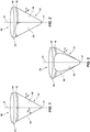
- FIG. 1 illustrates a side perspective view of the cutting element 10 showing the non-symmetrical configuration of the cutting tip 13 about the longitudinal axis 11.
- FIG. 2 which is a perspective view of the cutting element 10 taken from a viewpoint approximately 45 degrees clockwise of that of FIG. 1 , shows the flat cutting surface 18 of the cutting tip 13.
- FIG. 3 illustrates a front perspective view of the cutting element 10, taken from a viewpoint approximately ninety degrees (90°) clockwise of that of FIG. 1 , in which the cutting tip 13 is symmetrical about the longitudinal axis 11.
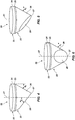
- another embodiment of the present disclosure includes a cutting element 20 having a longitudinal axis 21, a substrate base 22, and a cutting tip 23.
- the substrate base 22 may have a generally cylindrical shape.
- the longitudinal axis 21 may extend through a center of the substrate base 22 in an orientation that may be at least substantially parallel to a lateral side surface 24 of the substrate base 22 (e.g., in an orientation that may be perpendicular to a generally circular cross-section of the substrate base 22).
- the lateral side surface 24 of the substrate base 22 may be coextensive and continuous with a generally cylindrical lateral side surface 25 of the cutting tip 23.
- the cutting tip 23 also includes a conical surface 26, an apex 27, and a flat cutting surface 28.
- a portion of the conical surface 26 may extend between the edge of the flat cutting surface 28 and the generally cylindrical lateral side surface 25 of the cutting tip 23.
- the conical surface 26 may be defined by an angle ⁇ 2 existing between the conical surface 26 and a phantom line extending from the generally cylindrical lateral side surface 25 of the cutting tip 23.
- the angle ⁇ 2 may be within a range of from about thirty degrees (30°) to about sixty degrees (60°).
- the conical surface 26 may extend from the generally cylindrical lateral side surface 25 to the apex 27, and may extend to the edges of the flat cutting surface 28.
- the location of the apex 27 may be offset from the longitudinal axis 21.
- the flat cutting surface 28 may extend from a location at least substantially proximate the apex 27 to a location on the cutting element 20 at a selected or predetermined distance from the apex 27, such that an angle ⁇ 2 between the longitudinal axis 21 and the flat cutting surface 28 may be within a range of from about fifteen degrees (15°) to about ninety degrees (90°). Portions of the cutting tip 23, such as the flat cutting surface 28, may be polished.
- the angle ⁇ 2 is about thirty degrees (30°), the apex 27 is offset from the longitudinal axis 21, and the flat cutting surface 28 extends from the apex 27 to a location on the conical surface 26 of the cutting tip 23.
- the angle ⁇ 2 is about sixty degrees (60°).
- the viewing angles represented by FIGS. 4-6 correspond, respectively, to those of FIGS. 1-3 .
- Each of the cutting tips 13 and 23 may comprise a polycrystalline diamond (PCD) material. Certain regions of the cutting tips 13 and 23, or the entire cutting tips 13 and 23, optionally may be processed (e.g., etched) to remove metal binder from between the interbonded diamond grains of the PCD material of each of the cutting tips 13 and 23, such that each of the cutting tips 13 and 23 are relatively more thermally stable.
- Each of the cutting tips 13 and 23 may be formed on their respective substrate bases 12 and 22, or each of the cutting tips 13 and 23 and their respective substrate bases 12 and 22 may be separately formed and subsequently attached together. Each of the substrate bases 12 and 22 may be formed from a material that is relatively hard and resistant to wear.
- the substrate bases 12 and 22 may be at least substantially comprised of a cemented carbide material, such as cobalt-cemented tungsten carbide.
- the cutting tips 13 and 23 may be formed for use without the respective substrate bases 12 and 22 (e.g., the substrate bases 12 and 22 may be omitted from the respective cutting elements 10 and 20).
- an entirety of the cutting elements 10 and 20 e.g., the cutting tips 13 and 23, and the substrate bases 12 and 22
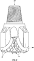
- FIG. 7 is a simplified perspective view of a fix-cutter rotary drill bit 100, which includes a plurality of the cutting elements 10 and 20 attached to blades 101 on the body of the drill bit 100.
- the drill bit 100 may include only cutting elements 10.
- the drill bit 100 may include only cutting elements 20.
- FIG. 8 is a simplified front view of a roller cone rotary drill bit 200, which includes a plurality of the cutting elements 10 and 20 attached to roller cones 201 thereof.
- the drill bit 200 may include only cutting elements 10.
- the drill bit 200 may include only cutting elements 20.
- the cutting elements 10 and 20 may each be attached to a portion 400 of the earth-boring tool such that at least a portion of the respective flat cutting surfaces 18 and 28 contact a surface 300 of the subterranean formation within the wellbore.
- the portion 400 of the earth-boring tool may be a portion of a fixed cutter earth-boring rotary drill bit, such as the drill bit 100 depicted in FIG. 7 , or a portion of a roller cone earth-boring rotary drill bit, such as the drill bit 200 depicted in FIG. 8 .
- a shape and configuration of each of the cutting elements 10 and 20 may enable versatility in orienting each of the cutting elements 10 and 20 relative to the surface 300 of the subterranean formation.
- effective back rake angles ⁇ 1 and ⁇ 2 between the respective flat cutting surfaces 18 and 28 and a reference plane 500 at least substantially perpendicular to the surface 300 of the subterranean formation may be negative (i.e., effective forward rake), positive (i.e., effective back rake), or neutral (i.e., effective neutral rake).
- the effective back rake angles ⁇ 1 and ⁇ 2 may be considered negative where the corresponding flat cutting surfaces 18 and 28 are behind the reference plane 500 in the direction of cutter movement (i.e., the flat cutting surfaces 18 and 28 form an obtuse angle with the surface 300 of the subterranean formation), as depicted in FIGS. 9 and 10 .
- the effective back rake angles ⁇ 1 and ⁇ 2 may be considered positive where the respective flat cutting surfaces 18 and 28 are ahead of the reference plane 500 in the direction of cutter movement (i.e., the flat cutting surfaces 18 and 28 form an acute angle with the surface of the subterranean formation 300), as depicted in FIGS. 11-16 .
- the effective back rake angles ⁇ 1 and ⁇ 2 may be considered neutral where the respective flat cutting surfaces 18 and 28 are parallel with the reference plane 500 (i.e., the flat cutting surfaces 18 and 28 substantially form a right angle with the surface of subterranean formation 300), as depicted in FIGS. 17 and 18 .
- the effective back rake angles ⁇ 1 and ⁇ 2 of the corresponding cutting elements 10 and 20 may be within a range of from about thirty degrees (30°) negative back rake to about forty-five degrees (45°) positive back rake relative to the reference plane 500.
- Subterranean formation cuttings may be deflected over and across the flat cutting surfaces 18 and 28 in directions that may be up and away from the surface 300 of the subterranean formation.
- a magnitude of each of the effective rake angles ⁇ 1 and ⁇ 2 may be at least partially determined by an orientation in which each of the respective cutting elements 10 and 20 is attached to the earth-boring tool.
- each of the cutting elements 10 and 20 may be attached to the earth-boring tool as to include respective physical back rake angles ⁇ 1 and ⁇ 2 that may be negative (i.e., physical forward rake), positive (i.e., physical back rake), or neutral (i.e., physical neutral rake).
- the physical back rake angles ⁇ 1 and ⁇ 2 may be considered negative where at least a portion of the respective longitudinal axes 11 and 21 extending through the respective cutting elements 10 and 20 are behind the reference plane 500 (i.e., the longitudinal axes 11 and 21 form an obtuse angle with the surface of the subterranean formation 300), as in depicted in FIGS. 9, 10 , and 15-18 (the vertically opposite physical back rake angles ⁇ 1 and ⁇ 2 being marked therein).
- the physical back rake angles ⁇ 1 and ⁇ 2 may be considered positive where at least a portion of the corresponding longitudinal axes 11 and 21 extending through the cutting elements 10 and 20 are ahead the reference plane 500 (i.e., the longitudinal axes form an acute angle with the surface of the subterranean formation 300), as depicted in FIGS. 11 and 12 (the vertically opposite physical back rake angles ⁇ 1 and ⁇ 2 being marked therein).
- the physical back rake angles ⁇ 1 and ⁇ 2 may be considered neutral where the corresponding longitudinal axes 11 and 21 are parallel with the reference plane 500, as depicted in FIGS. 13 and 14 .
- each of the effective back rake angles ⁇ 1 and ⁇ 2 may also be affected by the magnitudes of the angles ⁇ 1 and ⁇ 2 between the longitudinal axes 11 and 21 and the flat cutting surfaces 18 and 28, respectively.
- the magnitudes of the angles ⁇ 1 and ⁇ 2 may be influenced at least by the respective locations of the apex 17 and the apex 27 on the corresponding cutting tips 13 and 23, the length of the respective flat cutting surfaces 18 and 28, and the respective angles ⁇ 1 and ⁇ 2 between the corresponding generally conical surfaces 16 and 26 and the corresponding phantom lines extending from the generally cylindrical lateral side surfaces 15 and 25 of the cutting elements 10 and 20.
- the physical back rake angles ⁇ 1 and ⁇ 2 , the size and shape of the flat cutting surfaces 18 and 28, and the effective back rake angles ⁇ 1 and ⁇ 2 of the cutting tips 13 and 23, respectively, may each be tailored to optimize the performance of the cutting elements 10 and 20 for the earth-boring tool being used and characteristics of the surface 300 of the subterranean formation 300.
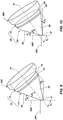
- FIGS. 9 and 10 illustrate that the cutting elements 10 and 20 may be formed and oriented on an earth-boring tool such that the corresponding physical back rake angles ⁇ 1 and ⁇ 2 are negative (i.e., physical forward rake) and the effective back rake angles ⁇ 1 and ⁇ 2 are negative (i.e., effective forward rake).
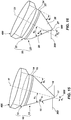
- FIG. 9 shows the side perspective view of the embodiment of the cutting element 10 illustrated in FIG. 1 , as oriented on the earth-boring tool to include a physical back rake angle ⁇ 1 that is negative.
- FIG. 10 shows the side perspective view of the embodiment of the cutting element 20 illustrated in FIG. 4 , as oriented on the earth-boring tool to include a physical back rake angle ⁇ 2 that is negative.
- the corresponding effective back rake angles ⁇ 1 and ⁇ 2 may be closer to neutral.
- the corresponding physical rake angles ⁇ 1 and ⁇ 2 may be more negative to facilitate effective back rake angles ⁇ 1 and ⁇ 2 that are negative.
- the corresponding physical back rake angles ⁇ 1 and ⁇ 2 may be less negative (i.e., closer to zero degrees), while still including effective back rake angles ⁇ 1 and ⁇ 2 that are negative.
- FIGS. 11 and 12 illustrate that the cutting elements 10 and 20 may be formed and oriented on an earth-boring tool such that the corresponding physical back rake angles ⁇ 1 and ⁇ 2 are positive (i.e., physical back rake) and the respective effective back rake angles ⁇ 1 and ⁇ 2 are positive (i.e., effective back rake).
- FIG. 11 shows the side perspective view of the embodiment of the cutting element 10 illustrated in FIG. 1 , as oriented on the earth-boring tool to include a physical back rake angle ⁇ 1 that is positive.
- FIG. 12 shows the side perspective view of the embodiment of the cutting element 20 illustrated in FIG. 4 , as oriented on the earth-boring tool to include a physical back rake angle ⁇ 2 that is positive.
- the corresponding effective back rake angles ⁇ 1 and ⁇ 2 may be more positive.
- the corresponding physical rake angles ⁇ 1 and ⁇ 2 may be more negative to facilitate effective back rake angles ⁇ 1 and ⁇ 2 that are within forty-five degrees (45°) of positive back rake angle relative to the reference plane 500.
- the corresponding physical rake angles ⁇ 1 and ⁇ 2 may be more positive while still including respective back rake angles ⁇ 1 and ⁇ 2 within forty-five degrees (45°) of positive back rake angle relative to the reference plane 500.
- FIGS. 13 and 14 illustrate that cutting elements 10 and 20 may be formed and oriented on an earth-boring tool such that the corresponding effective back rake angles ⁇ 1 and ⁇ 2 are positive (i.e., effective back rake), and respective physical back rake angles ⁇ 1 and ⁇ 2 are neutral (i.e., physical neutral rake).
- FIG. 13 shows the side perspective view of the embodiment of the cutting element 10 illustrated in FIG. 1 , as oriented on the earth-boring tool to include a physical back rake angle ⁇ 1 that is neutral.
- FIG. 14 shows the side perspective view of the embodiment of the cutting element 20 illustrated in FIG. 4 , as oriented on the earth-boring tool to include a physical back rake angle ⁇ 2 that is neutral.
- the magnitudes of the angles ⁇ 1 and ⁇ 2 may affect the sign and magnitude of the effective back rake angles ⁇ 1 and ⁇ 2 .
- the corresponding effective back rake angles ⁇ 1 and ⁇ 2 may be closer to forty-five degrees (45°) of positive back rake angle relative to the reference plane 500.
- the corresponding effective back rake angles ⁇ 1 and ⁇ 2 may be closer to neutral.
- FIGS. 15 and 16 illustrate that cutting elements 10 and 20 may be formed and oriented on an earth-boring tool such that the corresponding the effective back rake angles ⁇ 1 and ⁇ 2 are positive (i.e., effective back rake), and the respective physical back rake angles ⁇ 1 and ⁇ 2 are negative (i.e., physical forward rake).
- FIG. 15 shows the side perspective view of the embodiment of the cutting element 10 illustrated in FIG. 1 , as oriented on the earth-boring tool to include a physical back rake angle ⁇ 1 that is negative.
- FIG. 16 shows the side perspective view of the embodiment of the cutting element 20 illustrated in FIG. 4 , as oriented on the earth-boring tool to include a physical back rake angle ⁇ 2 that is negative.
- the corresponding effective back rake angles ⁇ 1 and ⁇ 2 may be more positive. In embodiments including relatively larger angles ⁇ 1 and ⁇ 2 , the corresponding physical rake angles ⁇ 1 and ⁇ 2 may be more negative to facilitate effective back rake angles ⁇ 1 and ⁇ 2 that are about forty-five degrees (45°) of positive back rake to the reference plane 500 or less. Conversely, in embodiments including relatively smaller angles ⁇ 1 and ⁇ 2 , the effective back rake angles ⁇ 1 and ⁇ 2 may be closer to neutral. In at least some embodiments including relatively smaller angles ⁇ 1 and ⁇ 2 , the corresponding physical back rake angles ⁇ 1 and ⁇ 2 may be more positive to facilitate effective back rake angles ⁇ 1 and ⁇ 2 that are negative.
- FIGS. 17 and 18 illustrate that cutting elements 10 and 20 may be formed and oriented on an earth-boring tool such that the corresponding the effective back rake angles ⁇ 1 and ⁇ 2 are neutral (i.e., effective back rake), and the physical back rake angles ⁇ 1 and ⁇ 2 are negative (i.e., physical forward rake).
- FIG. 17 shows the side perspective view of the embodiment of the cutting element 10 illustrated in FIG. 1 , as oriented on the earth-boring tool to include a physical back rake angle ⁇ 1 that is negative.
- FIG. 18 shows the side perspective view of the embodiment of the cutting element 20 illustrated in FIG. 4 , as oriented on the earth-boring tool to include a physical back rake angle ⁇ 2 that is negative.
- the corresponding physical back rake angles ⁇ 1 and ⁇ 2 may be more negative to facilitate corresponding effective back rake angles ⁇ 1 and ⁇ 2 that are neutral. Conversely, in embodiments including relatively smaller angles ⁇ 1 and ⁇ 2 , the corresponding physical back rake angles ⁇ 1 and ⁇ 2 may be more positive to facilitate corresponding effective back rake angles ⁇ 1 and ⁇ 2 that are neutral.
- the enhanced shape of the cutting elements described herein may be used to improve the behavior and durability of the cutting elements when drilling in subterranean earth formations.
- the shape of the cutting elements may allow the cutting element to fracture and damage the formation, while also providing increased efficiency in the removal of the fractured formation material from the subterranean surface of the wellbore.
- the shape of the cutting elements may be used to provide a positive, negative, or neutral effective back rake angle, regardless of whether the cutting element has a positive, negative, or neutral physical back rake angle.
Landscapes
- Engineering & Computer Science (AREA)
- Mechanical Engineering (AREA)
- Geology (AREA)
- Mining & Mineral Resources (AREA)
- Life Sciences & Earth Sciences (AREA)
- Chemical & Material Sciences (AREA)
- Geochemistry & Mineralogy (AREA)
- General Life Sciences & Earth Sciences (AREA)
- Physics & Mathematics (AREA)
- Environmental & Geological Engineering (AREA)
- Fluid Mechanics (AREA)
- Crystallography & Structural Chemistry (AREA)
- Manufacturing & Machinery (AREA)
- Organic Chemistry (AREA)
- Metallurgy (AREA)
- Materials Engineering (AREA)
- Earth Drilling (AREA)
- Polishing Bodies And Polishing Tools (AREA)
- Drilling Tools (AREA)
- Processing Of Stones Or Stones Resemblance Materials (AREA)
Claims (12)
- Schneideelement (20), umfassend:eine Substratbasis (22) undein Volumen aus polykristallinem Diamantmaterial (23) an einem Ende der Substratbasis, wobei das Volumen aus polykristallinem Diamantmaterial Folgendes umfasst:einen Scheitelpunkt (27), der von einer Längsachse (21) versetzt ist, die sich durch eine Mitte der Substratbasis erstreckt; undeine ebene Schneidfläche, die sich von einem ersten Punkt am Scheitelpunkt zu einem zweiten Punkt auf dem Schneideelement näher an einer lateralen Seitenoberfläche (24) der Substratbasis erstreckt, dadurch gekennzeichnet, dass das Volumen aus polykristallinem Diamantmaterial ferner eine konische Oberfläche (26) umfasst.
- Schneideelement nach Anspruch 1, wobei der zweite Punkt eine Stelle auf dem Volumen aus polykristallinem Diamantmaterial umfasst.
- Schneideelement nach einem der Ansprüche 1 oder 2, wobei ein erster Winkel (φ2) innerhalb eines Bereichs von dreißig Grad (30°) bis sechzig Grad (60°) zwischen der konischen Oberfläche und einer Phantomlinie besteht, die sich von der lateralen Seitenoberfläche der Substratbasis erstreckt.
- Schneideelement nach Anspruch 1, wobei ein zweiter Winkel (a2) innerhalb eines Bereichs von fünfzehn Grad (15°) bis neunzig Grad (90°) zwischen der ebenen Schneidfläche und der Längsachse besteht.
- Schneideelement nach Anspruch 1, wobei ein erster Winkel (φ2) innerhalb eines Bereichs von dreißig Grad (30°) bis sechzig Grad (60°) zwischen der konischen Oberfläche und einer Phantomlinie besteht, die sich von der lateralen Seitenoberfläche der Substratbasis erstreckt, und wobei ein zweiter Winkel (a2) innerhalb eines Bereichs von fünfzehn Grad (15°) bis neunzig Grad (90°) zwischen der ebenen Schneidfläche und der Längsachse besteht.
- Schneideelement nach einem der vorstehenden Ansprüche, wobei das Volumen aus polykristallinem Diamant (23) eine zylindrische laterale Seitenoberfläche (25) aufweist, wobei die Substratbasis eine laterale Seitenoberfläche (24) aufweist, die koextensiv und kontinuierlich mit der zylindrischen lateralen Seitenoberfläche des Volumens aus polykristallinem Diamant ist, und wobei die konische Oberfläche (26) durch einen ersten Winkel (φ2) zwischen der konischen Oberfläche und einer Phantomlinie definiert ist, die sich von der zylindrischen lateralen Seitenoberfläche erstreckt.
- Verfahren zum Herstellen eines Schneideelements (20), umfassend:Bilden einer Substratbasis (22) undBereitstellen eines Volumens aus polykristallinem Diamantmaterial (23) an einem Ende einer Substratbasis, wobei das Volumen aus polykristallinem Diamantmaterial eine konische Oberfläche (26), einen Scheitelpunkt (27), der von einer Längsachse (21) versetzt ist, die sich durch eine Mitte der Substratbasis erstreckt, und eine ebene Schneidfläche (28) umfasst, die sich von einem ersten Punkt am Scheitelpunkt zu einem zweiten Punkt auf dem Schneideelement näher an einer lateralen Seitenoberfläche (24) der Substratbasis erstreckt.
- Verfahren nach Anspruch 7, wobei das Bereitstellen des Volumens aus polykristallinem Diamantmaterial an einem Ende der Substratbasis ferner das Bilden der konischen Oberfläche des Volumens aus polykristallinem Diamantmaterial an einem ersten Winkel (φ2) in einem Bereich von dreißig Grad (30°) bis sechzig Grad (60°) relativ zu einer Phantomlinie umfasst, die sich von einer lateralen Seitenoberfläche (24) der Substratbasis erstreckt.
- Verfahren nach Anspruch 7, wobei das Bereitstellen des Volumens aus polykristallinem Diamantmaterial ferner Folgendes umfasst:Bilden der konischen Oberfläche des Volumens aus polykristallinem Diamantmaterial in einem ersten Winkel (φ2) innerhalb eines Bereichs von dreißig Grad (30°) bis sechzig Grad (60°) relativ zu einer Phantomlinie, die sich von einer lateralen Seitenoberfläche der Substratbasis erstreckt; undBilden der ebenen Schneidfläche des Volumens aus polykristallinem Diamantmaterial in einem zweiten Winkel (a2) innerhalb eines Bereichs von fünfzehn Grad (15°) bis neunzig Grad (90°) relativ zur Längsachse.
- Verfahren nach Anspruch 7, wobei das Bereitstellen des Volumens aus polykristallinem Diamantmaterial auf der Substratbasis das Befestigen des Volumens aus polykristallinem Diamantmaterial an der Substratbasis nach dem Bilden von mindestens einem der konischen Oberfläche, des Scheitelpunktes und der ebenen Schneidfläche des Volumens aus polykristallinem Diamantmaterial umfasst.
- Verfahren nach Anspruch 7, wobei das Bereitstellen des Volumens aus polykristallinem Diamantmaterial auf der Substratbasis das Bilden von mindestens einem der konischen Oberfläche, des Scheitelpunktes und der ebenen Schneidfläche des Volumens aus polykristallinem Diamantmaterial umfasst, während das Volumen aus polykristallinem Diamantmaterial an der Substratbasis befestigt ist.
- Verfahren nach einem der Ansprüche 7 bis 11, wobei das Volumen aus polykristallinem Diamant (23) eine zylindrische laterale Seitenoberfläche (25) aufweist, wobei die Substratbasis eine laterale Seitenoberfläche (24) aufweist, die koextensiv und kontinuierlich mit der zylindrischen lateralen Seitenoberfläche des Volumens aus polykristallinem Diamant ist, und wobei die konische Oberfläche (26) durch einen ersten Winkel (φ2) zwischen der konischen Oberfläche und einer Phantomlinie definiert ist, die sich von der zylindrischen lateralen Seitenoberfläche erstreckt.
Applications Claiming Priority (3)
| Application Number | Priority Date | Filing Date | Title |
|---|---|---|---|
| US37155410P | 2010-08-06 | 2010-08-06 | |
| EP11815391.5A EP2601373B1 (de) | 2010-08-06 | 2011-08-05 | Geformte schneideelemente für erdbohrwerkzeuge, erdbohrwerkzeuge mit solchen schneideelementen und zugehörige verfahren |
| PCT/US2011/046820 WO2012019141A2 (en) | 2010-08-06 | 2011-08-05 | Shaped cutting elements for earth-boring tools, earth-boring tools including such cutting elements, and related methods |
Related Parent Applications (2)
| Application Number | Title | Priority Date | Filing Date |
|---|---|---|---|
| EP11815391.5A Division-Into EP2601373B1 (de) | 2010-08-06 | 2011-08-05 | Geformte schneideelemente für erdbohrwerkzeuge, erdbohrwerkzeuge mit solchen schneideelementen und zugehörige verfahren |
| EP11815391.5A Division EP2601373B1 (de) | 2010-08-06 | 2011-08-05 | Geformte schneideelemente für erdbohrwerkzeuge, erdbohrwerkzeuge mit solchen schneideelementen und zugehörige verfahren |
Publications (2)
| Publication Number | Publication Date |
|---|---|
| EP3540173A1 EP3540173A1 (de) | 2019-09-18 |
| EP3540173B1 true EP3540173B1 (de) | 2021-06-02 |
Family
ID=45555262
Family Applications (2)
| Application Number | Title | Priority Date | Filing Date |
|---|---|---|---|
| EP11815391.5A Active EP2601373B1 (de) | 2010-08-06 | 2011-08-05 | Geformte schneideelemente für erdbohrwerkzeuge, erdbohrwerkzeuge mit solchen schneideelementen und zugehörige verfahren |
| EP19171698.4A Active EP3540173B1 (de) | 2010-08-06 | 2011-08-05 | Geformte schneideelemente für erdbohrwerkzeuge, erdbohrwerkzeuge mit solchen schneideelementen und zugehörige verfahren |
Family Applications Before (1)
| Application Number | Title | Priority Date | Filing Date |
|---|---|---|---|
| EP11815391.5A Active EP2601373B1 (de) | 2010-08-06 | 2011-08-05 | Geformte schneideelemente für erdbohrwerkzeuge, erdbohrwerkzeuge mit solchen schneideelementen und zugehörige verfahren |
Country Status (11)
| Country | Link |
|---|---|
| US (2) | US9022149B2 (de) |
| EP (2) | EP2601373B1 (de) |
| CN (1) | CN103069099B (de) |
| BR (1) | BR112013002942A2 (de) |
| CA (1) | CA2807231C (de) |
| MX (1) | MX2013001239A (de) |
| RU (1) | RU2013109737A (de) |
| SA (1) | SA111320671B1 (de) |
| SG (1) | SG187724A1 (de) |
| WO (1) | WO2012019141A2 (de) |
| ZA (1) | ZA201300625B (de) |
Families Citing this family (31)
| Publication number | Priority date | Publication date | Assignee | Title |
|---|---|---|---|---|
| US7036611B2 (en) | 2002-07-30 | 2006-05-02 | Baker Hughes Incorporated | Expandable reamer apparatus for enlarging boreholes while drilling and methods of use |
| US8505634B2 (en) * | 2009-12-28 | 2013-08-13 | Baker Hughes Incorporated | Earth-boring tools having differing cutting elements on a blade and related methods |
| EP2531690B1 (de) * | 2010-02-05 | 2019-04-03 | Baker Hughes, a GE company, LLC | Geformte schneideelemente auf bohrmeisseln und anderen erdbohrwerkzeugen sowie verfahren zu ihrer formung |
| US8851207B2 (en) | 2011-05-05 | 2014-10-07 | Baker Hughes Incorporated | Earth-boring tools and methods of forming such earth-boring tools |
| SA111320671B1 (ar) | 2010-08-06 | 2015-01-22 | بيكر هوغيس انكور | عوامل القطع المشكلة لادوات ثقب الارض و ادوات ثقب الارض شاملة عوامل القطع هذه و الطرق المختصة بها |
| BR112013020374B1 (pt) | 2011-02-10 | 2020-08-25 | Smith International, Inc. | broca de perfuração e ferramenta de corte para fundo do poço |
| CA2839696C (en) | 2011-06-22 | 2019-10-29 | Smith International, Inc. | Fixed cutter drill bit with core fragmentation feature |
| US9500070B2 (en) | 2011-09-19 | 2016-11-22 | Baker Hughes Incorporated | Sensor-enabled cutting elements for earth-boring tools, earth-boring tools so equipped, and related methods |
| US9316058B2 (en) | 2012-02-08 | 2016-04-19 | Baker Hughes Incorporated | Drill bits and earth-boring tools including shaped cutting elements |
| US9493991B2 (en) | 2012-04-02 | 2016-11-15 | Baker Hughes Incorporated | Cutting structures, tools for use in subterranean boreholes including cutting structures and related methods |
| US10030452B2 (en) | 2013-03-14 | 2018-07-24 | Smith International, Inc. | Cutting structures for fixed cutter drill bit and other downhole cutting tools |
| US10309156B2 (en) | 2013-03-14 | 2019-06-04 | Smith International, Inc. | Cutting structures for fixed cutter drill bit and other downhole cutting tools |
| US9074471B2 (en) * | 2013-08-05 | 2015-07-07 | Kennametal Inc. | Insert with offset apex for a cutter bit and a cutter bit having the same |
| US20150060149A1 (en) * | 2013-09-04 | 2015-03-05 | Shear Bits, Ltd. | Drill bit having shear and pick-type cutters |
| US10287825B2 (en) | 2014-03-11 | 2019-05-14 | Smith International, Inc. | Cutting elements having non-planar surfaces and downhole cutting tools using such cutting elements |
| AU2016228143B2 (en) * | 2015-03-02 | 2019-05-30 | Valley Blades Limited | A sectional grader system for a mold board |
| US10307891B2 (en) | 2015-08-12 | 2019-06-04 | Us Synthetic Corporation | Attack inserts with differing surface finishes, assemblies, systems including same, and related methods |
| US10480254B2 (en) | 2017-07-06 | 2019-11-19 | Baker Hughes, A Ge Company, Llc | Drill bits having tailored depth of cut control features and related methods |
| CN107701111B (zh) * | 2017-10-25 | 2019-06-11 | 中国石油天然气股份有限公司 | 切削冲击齿、冲击钻头及其使用方法 |
| US10577870B2 (en) * | 2018-07-27 | 2020-03-03 | Baker Hughes, A Ge Company, Llc | Cutting elements configured to reduce impact damage related tools and methods—alternate configurations |
| US11187040B2 (en) | 2018-07-30 | 2021-11-30 | XR Downhole, LLC | Downhole drilling tool with a polycrystalline diamond bearing |
| US11014759B2 (en) | 2018-07-30 | 2021-05-25 | XR Downhole, LLC | Roller ball assembly with superhard elements |
| US10738821B2 (en) | 2018-07-30 | 2020-08-11 | XR Downhole, LLC | Polycrystalline diamond radial bearing |
| USD882701S1 (en) * | 2019-01-23 | 2020-04-28 | P&P Imports LLC | Game piece for a table game |
| US12031383B2 (en) * | 2019-03-07 | 2024-07-09 | Halliburton Energy Services, Inc. | Shaped cutter arrangements |
| CN114270060B (zh) * | 2019-05-29 | 2024-05-03 | Xr储备有限责任公司 | 用于金刚石对金刚石反应材料轴承接合的材料处理 |
| US12228177B2 (en) | 2020-05-29 | 2025-02-18 | Pi Tech Innovations Llc | Driveline with double conical bearing joints having polycrystalline diamond power transmission surfaces |
| CN116390698A (zh) | 2020-11-09 | 2023-07-04 | 圆周率科技创新有限公司 | 用于与金属表面滑动接合的连续金刚石表面轴承 |
| WO2022099186A1 (en) | 2020-11-09 | 2022-05-12 | Gregory Prevost | Diamond surface bearings for sliding engagement with metal surfaces |
| USD1023312S1 (en) * | 2022-03-18 | 2024-04-16 | Gc Corporation | Hemostatic agent material |
| WO2023201255A1 (en) | 2022-04-13 | 2023-10-19 | Pi Tech Innovations Llc | Polycrystalline diamond-on-metal bearings for use in low temperature and cryogenic conditions |
Family Cites Families (126)
| Publication number | Priority date | Publication date | Assignee | Title |
|---|---|---|---|---|
| US3459073A (en) | 1967-06-12 | 1969-08-05 | Timken Roller Bearing Co | Rock bit assembly and bit insert assembly process |
| US4373593A (en) | 1979-03-16 | 1983-02-15 | Christensen, Inc. | Drill bit |
| DE3039632C2 (de) | 1980-10-21 | 1982-12-16 | Christensen, Inc., 84115 Salt Lake City, Utah | Drehborhmeißel für Tiefbohrungen |
| DE3113109C2 (de) | 1981-04-01 | 1983-11-17 | Christensen, Inc., 84115 Salt Lake City, Utah | Drehbohrmeißel für Tiefbohrungen |
| US4440247A (en) | 1982-04-29 | 1984-04-03 | Sartor Raymond W | Rotary earth drilling bit |
| US4499958A (en) | 1983-04-29 | 1985-02-19 | Strata Bit Corporation | Drag blade bit with diamond cutting elements |
| USRE33757E (en) | 1984-06-07 | 1991-12-03 | Dresser Industries, Inc. | Diamond drill bit with varied cutting elements |
| US4602691A (en) | 1984-06-07 | 1986-07-29 | Hughes Tool Company | Diamond drill bit with varied cutting elements |
| US4823892A (en) | 1984-07-19 | 1989-04-25 | Nl Petroleum Products Limited | Rotary drill bits |
| GB8418481D0 (en) | 1984-07-19 | 1984-08-22 | Nl Petroleum Prod | Rotary drill bits |
| US4889017A (en) | 1984-07-19 | 1989-12-26 | Reed Tool Co., Ltd. | Rotary drill bit for use in drilling holes in subsurface earth formations |
| US4705124A (en) | 1986-08-22 | 1987-11-10 | Minnesota Mining And Manufacturing Company | Cutting element with wear resistant crown |
| US4722405A (en) | 1986-10-01 | 1988-02-02 | Dresser Industries, Inc. | Wear compensating rock bit insert |
| US4832139A (en) | 1987-06-10 | 1989-05-23 | Smith International, Inc. | Inclined chisel inserts for rock bits |
| US4854405A (en) | 1988-01-04 | 1989-08-08 | American National Carbide Company | Cutting tools |
| US4869330A (en) | 1988-01-20 | 1989-09-26 | Eastman Christensen Company | Apparatus for establishing hydraulic flow regime in drill bits |
| GB2218131B (en) | 1988-05-06 | 1992-03-25 | Reed Tool Co | Improvements in or relating to rotary drill bits |
| US4981184A (en) | 1988-11-21 | 1991-01-01 | Smith International, Inc. | Diamond drag bit for soft formations |
| US5172779A (en) | 1991-11-26 | 1992-12-22 | Smith International, Inc. | Radial crest insert |
| US5322138A (en) * | 1991-08-14 | 1994-06-21 | Smith International, Inc. | Chisel insert for rock bits |
| US5172777A (en) | 1991-09-26 | 1992-12-22 | Smith International, Inc. | Inclined chisel inserts for rock bits |
| US5244039A (en) | 1991-10-31 | 1993-09-14 | Camco Drilling Group Ltd. | Rotary drill bits |
| US5186268A (en) | 1991-10-31 | 1993-02-16 | Camco Drilling Group Ltd. | Rotary drill bits |
| US5592995A (en) | 1995-06-06 | 1997-01-14 | Baker Hughes Incorporated | Earth-boring bit having shear-cutting heel elements |
| US5890552A (en) | 1992-01-31 | 1999-04-06 | Baker Hughes Incorporated | Superabrasive-tipped inserts for earth-boring drill bits |
| US6332503B1 (en) | 1992-01-31 | 2001-12-25 | Baker Hughes Incorporated | Fixed cutter bit with chisel or vertical cutting elements |
| US5303785A (en) | 1992-08-25 | 1994-04-19 | Smith International, Inc. | Diamond back-up for PDC cutters |
| US5558170A (en) | 1992-12-23 | 1996-09-24 | Baroid Technology, Inc. | Method and apparatus for improving drill bit stability |
| GB2274474B (en) | 1993-01-21 | 1996-07-31 | Camco Drilling Group Ltd | Improvements in or relating to cutter assemblies for rotary drill bits |
| US5542485A (en) | 1993-07-08 | 1996-08-06 | Baker Hughes Incorporated | Earth-boring bit with improved cutting structure |
| GB9314954D0 (en) | 1993-07-16 | 1993-09-01 | Camco Drilling Group Ltd | Improvements in or relating to torary drill bits |
| US5379853A (en) * | 1993-09-20 | 1995-01-10 | Smith International, Inc. | Diamond drag bit cutting elements |
| US5505273A (en) | 1994-01-24 | 1996-04-09 | Smith International, Inc. | Compound diamond cutter |
| US5415244A (en) | 1994-02-28 | 1995-05-16 | Smith International, Inc. | Conical inserts for rolling cone rock bits |
| US6209420B1 (en) | 1994-03-16 | 2001-04-03 | Baker Hughes Incorporated | Method of manufacturing bits, bit components and other articles of manufacture |
| US5421423A (en) | 1994-03-22 | 1995-06-06 | Dresser Industries, Inc. | Rotary cone drill bit with improved cutter insert |
| US5595252A (en) | 1994-07-28 | 1997-01-21 | Flowdril Corporation | Fixed-cutter drill bit assembly and method |
| US5549171A (en) | 1994-08-10 | 1996-08-27 | Smith International, Inc. | Drill bit with performance-improving cutting structure |
| SE507098C2 (sv) * | 1994-10-12 | 1998-03-30 | Sandvik Ab | Stift av hårdmetall och bergborrkrona för slående borrning |
| EP0707130B1 (de) | 1994-10-15 | 2003-07-16 | Camco Drilling Group Limited | Drehbohrmeissel |
| US5607024A (en) | 1995-03-07 | 1997-03-04 | Smith International, Inc. | Stability enhanced drill bit and cutting structure having zones of varying wear resistance |
| GB2298665B (en) | 1995-03-08 | 1998-11-04 | Camco Drilling Group Ltd | Improvements in or relating to cutter assemblies for rotary drill bits |
| US5697462A (en) | 1995-06-30 | 1997-12-16 | Baker Hughes Inc. | Earth-boring bit having improved cutting structure |
| US5904213A (en) | 1995-10-10 | 1999-05-18 | Camco International (Uk) Limited | Rotary drill bits |
| US6089336A (en) | 1995-10-10 | 2000-07-18 | Camco International (Uk) Limited | Rotary drill bits |
| US5706906A (en) | 1996-02-15 | 1998-01-13 | Baker Hughes Incorporated | Superabrasive cutting element with enhanced durability and increased wear life, and apparatus so equipped |
| US5758733A (en) | 1996-04-17 | 1998-06-02 | Baker Hughes Incorporated | Earth-boring bit with super-hard cutting elements |
| US6571891B1 (en) | 1996-04-17 | 2003-06-03 | Baker Hughes Incorporated | Web cutter |
| US6059054A (en) | 1996-06-21 | 2000-05-09 | Smith International, Inc. | Non-symmetrical stress-resistant rotary drill bit cutter element |
| US5813485A (en) * | 1996-06-21 | 1998-09-29 | Smith International, Inc. | Cutter element adapted to withstand tensile stress |
| FR2756002B1 (fr) | 1996-11-20 | 1999-04-02 | Total Sa | Outil de forage a lames avec taillants de reserve et canaux d'evacuation des deblais generes par les taillants |
| US5871060A (en) | 1997-02-20 | 1999-02-16 | Jensen; Kenneth M. | Attachment geometry for non-planar drill inserts |
| GB9708428D0 (en) | 1997-04-26 | 1997-06-18 | Camco Int Uk Ltd | Improvements in or relating to rotary drill bits |
| US6053263A (en) | 1997-06-20 | 2000-04-25 | Baker Hughes Incorporated | Cutting element tip configuration for an earth-boring bit |
| US7025156B1 (en) | 1997-11-18 | 2006-04-11 | Douglas Caraway | Rotary drill bit for casting milling and formation drilling |
| CA2261495A1 (en) | 1998-03-13 | 1999-09-13 | Praful C. Desai | Method for milling casing and drilling formation |
| US6105694A (en) | 1998-06-29 | 2000-08-22 | Baker Hughes Incorporated | Diamond enhanced insert for rolling cutter bit |
| GB2339810B (en) | 1998-07-14 | 2002-05-22 | Camco Internat | A method of determining characteristics of a rotary drag-type drill bit |
| GB2339811B (en) | 1998-07-22 | 2002-05-22 | Camco Internat | Improvements in or relating to rotary drill bits |
| US6401844B1 (en) | 1998-12-03 | 2002-06-11 | Baker Hughes Incorporated | Cutter with complex superabrasive geometry and drill bits so equipped |
| US6176333B1 (en) * | 1998-12-04 | 2001-01-23 | Baker Huges Incorporated | Diamond cap cutting elements with flats |
| US6241035B1 (en) * | 1998-12-07 | 2001-06-05 | Smith International, Inc. | Superhard material enhanced inserts for earth-boring bits |
| US6290008B1 (en) | 1998-12-07 | 2001-09-18 | Smith International, Inc. | Inserts for earth-boring bits |
| US6227318B1 (en) * | 1998-12-07 | 2001-05-08 | Smith International, Inc. | Superhard material enhanced inserts for earth-boring bits |
| US6302224B1 (en) | 1999-05-13 | 2001-10-16 | Halliburton Energy Services, Inc. | Drag-bit drilling with multi-axial tooth inserts |
| US8401831B2 (en) | 2000-03-13 | 2013-03-19 | Smith International, Inc. | Methods for designing secondary cutting structures for a bottom hole assembly |
| US6328117B1 (en) | 2000-04-06 | 2001-12-11 | Baker Hughes Incorporated | Drill bit having a fluid course with chip breaker |
| DE60140617D1 (de) | 2000-09-20 | 2010-01-07 | Camco Int Uk Ltd | Polykristalliner diamant mit einer an katalysatormaterial abgereicherten oberfläche |
| US6408958B1 (en) | 2000-10-23 | 2002-06-25 | Baker Hughes Incorporated | Superabrasive cutting assemblies including cutters of varying orientations and drill bits so equipped |
| US6615934B2 (en) | 2001-08-15 | 2003-09-09 | Smith International, Inc. | PDC drill bit having cutting structure adapted to improve high speed drilling performance |
| US6997273B2 (en) * | 2002-11-15 | 2006-02-14 | Smith International, Inc. | Blunt faced cutter element and enhanced drill bit and cutting structure |
| US6883624B2 (en) | 2003-01-31 | 2005-04-26 | Smith International, Inc. | Multi-lobed cutter element for drill bit |
| US6814926B2 (en) | 2003-03-19 | 2004-11-09 | 3D Systems Inc. | Metal powder composition for laser sintering |
| US20040231894A1 (en) | 2003-05-21 | 2004-11-25 | Dvorachek Harold A | Rotary tools or bits |
| AR044550A1 (es) | 2003-05-26 | 2005-09-21 | Shell Int Research | Cabeza de perforacion y sistema y metodo para perforar un pozo de perforacion en una formacion de tierra |
| AR044485A1 (es) | 2003-06-12 | 2005-09-14 | Shell Int Research | Mecha perforadora con percusion, sistema de perforacion que incluye dicha mecha perforadora y un metodo para perforar un pozo |
| US7013999B2 (en) * | 2003-07-28 | 2006-03-21 | Smith International, Inc. | Wedge tooth cutter element for drill bit |
| US7011169B2 (en) | 2003-11-10 | 2006-03-14 | Baker Hughes Incorporated | Expanded coverage carbide compact |
| US7070011B2 (en) | 2003-11-17 | 2006-07-04 | Baker Hughes Incorporated | Steel body rotary drill bits including support elements affixed to the bit body at least partially defining cutter pocket recesses |
| US7798257B2 (en) | 2004-04-30 | 2010-09-21 | Smith International, Inc. | Shaped cutter surface |
| US7455126B2 (en) | 2004-05-25 | 2008-11-25 | Shell Oil Company | Percussive drill bit, drilling system comprising such a drill bit and method of drilling a bore hole |
| US7152703B2 (en) * | 2004-05-27 | 2006-12-26 | Baker Hughes Incorporated | Compact for earth boring bit with asymmetrical flanks and shoulders |
| CN2743526Y (zh) * | 2004-10-15 | 2005-11-30 | 江汉石油钻头股份有限公司 | 偏顶楔形齿 |
| US8109349B2 (en) | 2006-10-26 | 2012-02-07 | Schlumberger Technology Corporation | Thick pointed superhard material |
| GB2427633B (en) | 2005-05-17 | 2007-08-15 | Smith International | Drill bit and method of designing a drill bit |
| WO2007056554A1 (en) | 2005-11-08 | 2007-05-18 | Baker Hughes Incorporated | Methods for optimizing efficiency and durability of rotary drag bits and rotary drag bits designed for optimal efficiency and durability |
| US7641002B2 (en) | 2005-11-21 | 2010-01-05 | Hall David R | Drill bit |
| EP1989391B1 (de) | 2006-02-23 | 2010-12-29 | Baker Hughes Incorporated | Reserveschneideinsatz für rotationsbohrspitze |
| US7694756B2 (en) | 2006-03-23 | 2010-04-13 | Hall David R | Indenting member for a drill bit |
| US20070261890A1 (en) | 2006-05-10 | 2007-11-15 | Smith International, Inc. | Fixed Cutter Bit With Centrally Positioned Backup Cutter Elements |
| US8061453B2 (en) | 2006-05-26 | 2011-11-22 | Smith International, Inc. | Drill bit with asymmetric gage pad configuration |
| US8500209B2 (en) | 2006-08-11 | 2013-08-06 | Schlumberger Technology Corporation | Manually rotatable tool |
| US8622155B2 (en) | 2006-08-11 | 2014-01-07 | Schlumberger Technology Corporation | Pointed diamond working ends on a shear bit |
| US20080035389A1 (en) | 2006-08-11 | 2008-02-14 | Hall David R | Roof Mining Drill Bit |
| US8616305B2 (en) | 2006-08-11 | 2013-12-31 | Schlumberger Technology Corporation | Fixed bladed bit that shifts weight between an indenter and cutting elements |
| US8567532B2 (en) | 2006-08-11 | 2013-10-29 | Schlumberger Technology Corporation | Cutting element attached to downhole fixed bladed bit at a positive rake angle |
| US8714285B2 (en) | 2006-08-11 | 2014-05-06 | Schlumberger Technology Corporation | Method for drilling with a fixed bladed bit |
| US8122980B2 (en) | 2007-06-22 | 2012-02-28 | Schlumberger Technology Corporation | Rotary drag bit with pointed cutting elements |
| US8590644B2 (en) | 2006-08-11 | 2013-11-26 | Schlumberger Technology Corporation | Downhole drill bit |
| US8215420B2 (en) | 2006-08-11 | 2012-07-10 | Schlumberger Technology Corporation | Thermally stable pointed diamond with increased impact resistance |
| US7743855B2 (en) * | 2006-09-05 | 2010-06-29 | Smith International, Inc. | Drill bit with cutter element having multifaceted, slanted top cutting surface |
| US8960337B2 (en) | 2006-10-26 | 2015-02-24 | Schlumberger Technology Corporation | High impact resistant tool with an apex width between a first and second transitions |
| US8205692B2 (en) | 2007-01-03 | 2012-06-26 | Smith International, Inc. | Rock bit and inserts with a chisel crest having a broadened region |
| RU2009131831A (ru) | 2007-01-25 | 2011-02-27 | Бейкер Хьюз Инкорпорейтед (Us) | Лопастное долото для роторного бурения |
| US8016059B2 (en) | 2007-02-09 | 2011-09-13 | Smith International, Inc. | Gage insert |
| US20080223622A1 (en) | 2007-03-13 | 2008-09-18 | Duggan James L | Earth-boring tools having pockets for receiving cutting elements therein and methods of forming such pockets and earth-boring tools |
| US7845435B2 (en) | 2007-04-05 | 2010-12-07 | Baker Hughes Incorporated | Hybrid drill bit and method of drilling |
| US7703557B2 (en) | 2007-06-11 | 2010-04-27 | Smith International, Inc. | Fixed cutter bit with backup cutter elements on primary blades |
| US7836978B2 (en) | 2007-06-15 | 2010-11-23 | Baker Hughes Incorporated | Cutting elements for casing component drill out and subterranean drilling, earth boring drag bits and tools including same and methods of use |
| US8011456B2 (en) | 2007-07-18 | 2011-09-06 | Baker Hughes Incorporated | Rotationally indexable cutting elements and drill bits therefor |
| US8678111B2 (en) | 2007-11-16 | 2014-03-25 | Baker Hughes Incorporated | Hybrid drill bit and design method |
| US9016407B2 (en) | 2007-12-07 | 2015-04-28 | Smith International, Inc. | Drill bit cutting structure and methods to maximize depth-of-cut for weight on bit applied |
| WO2009146078A1 (en) | 2008-04-01 | 2009-12-03 | Smith International, Inc. | Fixed cutter bit with backup cutter elements on secondary blades |
| US8540037B2 (en) | 2008-04-30 | 2013-09-24 | Schlumberger Technology Corporation | Layered polycrystalline diamond |
| US7628233B1 (en) | 2008-07-23 | 2009-12-08 | Hall David R | Carbide bolster |
| WO2010080476A2 (en) | 2008-12-18 | 2010-07-15 | Smith International, Inc. | Method of designing a bottom hole assembly and a bottom hole assembly |
| US8061457B2 (en) | 2009-02-17 | 2011-11-22 | Schlumberger Technology Corporation | Chamfered pointed enhanced diamond insert |
| US20100326740A1 (en) | 2009-06-26 | 2010-12-30 | Hall David R | Bonded Assembly Having Low Residual Stress |
| US20110083906A1 (en) | 2009-10-14 | 2011-04-14 | Hall David R | Fixed Bladed Drill Bit Force Balanced by Blade Spacing |
| US8505634B2 (en) | 2009-12-28 | 2013-08-13 | Baker Hughes Incorporated | Earth-boring tools having differing cutting elements on a blade and related methods |
| EP2531690B1 (de) | 2010-02-05 | 2019-04-03 | Baker Hughes, a GE company, LLC | Geformte schneideelemente auf bohrmeisseln und anderen erdbohrwerkzeugen sowie verfahren zu ihrer formung |
| US8851207B2 (en) | 2011-05-05 | 2014-10-07 | Baker Hughes Incorporated | Earth-boring tools and methods of forming such earth-boring tools |
| SA111320671B1 (ar) | 2010-08-06 | 2015-01-22 | بيكر هوغيس انكور | عوامل القطع المشكلة لادوات ثقب الارض و ادوات ثقب الارض شاملة عوامل القطع هذه و الطرق المختصة بها |
| US20120125687A1 (en) | 2010-11-24 | 2012-05-24 | Tiger 19 Partners, Ltd. | Hard Rock Rotary Drill Bit and Method of Drilling Using Crowned Cutter Elements |
| BR112013020374B1 (pt) | 2011-02-10 | 2020-08-25 | Smith International, Inc. | broca de perfuração e ferramenta de corte para fundo do poço |
| US9316058B2 (en) | 2012-02-08 | 2016-04-19 | Baker Hughes Incorporated | Drill bits and earth-boring tools including shaped cutting elements |
-
2011
- 2011-08-03 SA SA111320671A patent/SA111320671B1/ar unknown
- 2011-08-05 EP EP11815391.5A patent/EP2601373B1/de active Active
- 2011-08-05 CA CA2807231A patent/CA2807231C/en active Active
- 2011-08-05 CN CN201180039361.1A patent/CN103069099B/zh active Active
- 2011-08-05 US US13/204,459 patent/US9022149B2/en active Active
- 2011-08-05 EP EP19171698.4A patent/EP3540173B1/de active Active
- 2011-08-05 MX MX2013001239A patent/MX2013001239A/es not_active Application Discontinuation
- 2011-08-05 SG SG2013008859A patent/SG187724A1/en unknown
- 2011-08-05 RU RU2013109737/03A patent/RU2013109737A/ru not_active Application Discontinuation
- 2011-08-05 WO PCT/US2011/046820 patent/WO2012019141A2/en not_active Ceased
- 2011-08-05 BR BR112013002942A patent/BR112013002942A2/pt not_active IP Right Cessation
-
2013
- 2013-01-23 ZA ZA2013/00625A patent/ZA201300625B/en unknown
-
2015
- 2015-04-14 US US14/686,093 patent/US9458674B2/en active Active
Non-Patent Citations (1)
| Title |
|---|
| None * |
Also Published As
| Publication number | Publication date |
|---|---|
| CA2807231A1 (en) | 2012-02-09 |
| SA111320671B1 (ar) | 2015-01-22 |
| SG187724A1 (en) | 2013-03-28 |
| MX2013001239A (es) | 2013-04-03 |
| US9458674B2 (en) | 2016-10-04 |
| EP2601373B1 (de) | 2019-07-24 |
| CN103069099B (zh) | 2016-08-03 |
| CA2807231C (en) | 2016-06-28 |
| WO2012019141A2 (en) | 2012-02-09 |
| CN103069099A (zh) | 2013-04-24 |
| EP2601373A4 (de) | 2016-11-09 |
| WO2012019141A3 (en) | 2012-03-29 |
| EP3540173A1 (de) | 2019-09-18 |
| EP2601373A2 (de) | 2013-06-12 |
| ZA201300625B (en) | 2014-03-26 |
| US20120031674A1 (en) | 2012-02-09 |
| BR112013002942A2 (pt) | 2016-06-07 |
| RU2013109737A (ru) | 2014-09-20 |
| US9022149B2 (en) | 2015-05-05 |
| US20150218890A1 (en) | 2015-08-06 |
Similar Documents
| Publication | Publication Date | Title |
|---|---|---|
| EP3540173B1 (de) | Geformte schneideelemente für erdbohrwerkzeuge, erdbohrwerkzeuge mit solchen schneideelementen und zugehörige verfahren | |
| US10450807B2 (en) | Earth-boring tools having shaped cutting elements | |
| US9752387B2 (en) | Plow-shaped cutting elements for earth-boring tools, earth-boring tools including such cutting elements, and related methods | |
| EP3521549B1 (de) | Geformte schneideelemente für erdbohrwerkzeuge und erdbohrwerkzeuge mit solchen schneideelementen | |
| US10221628B2 (en) | Methods of repairing cutting element pockets in earth-boring tools with depth-of-cut control features | |
| US10047565B2 (en) | Cutting element retention for high exposure cutting elements on earth-boring tools | |
| US10047569B2 (en) | Cutting elements having laterally elongated shapes for use with earth-boring tools, earth-boring tools including such cutting elements, and related methods | |
| US9303461B2 (en) | Cutting elements having curved or annular configurations for earth-boring tools, earth-boring tools including such cutting elements, and related methods |
Legal Events
| Date | Code | Title | Description |
|---|---|---|---|
| PUAI | Public reference made under article 153(3) epc to a published international application that has entered the european phase |
Free format text: ORIGINAL CODE: 0009012 |
|
| STAA | Information on the status of an ep patent application or granted ep patent |
Free format text: STATUS: THE APPLICATION HAS BEEN PUBLISHED |
|
| AC | Divisional application: reference to earlier application |
Ref document number: 2601373 Country of ref document: EP Kind code of ref document: P |
|
| AK | Designated contracting states |
Kind code of ref document: A1 Designated state(s): AL AT BE BG CH CY CZ DE DK EE ES FI FR GB GR HR HU IE IS IT LI LT LU LV MC MK MT NL NO PL PT RO RS SE SI SK SM TR |
|
| STAA | Information on the status of an ep patent application or granted ep patent |
Free format text: STATUS: REQUEST FOR EXAMINATION WAS MADE |
|
| 17P | Request for examination filed |
Effective date: 20191218 |
|
| RBV | Designated contracting states (corrected) |
Designated state(s): AL AT BE BG CH CY CZ DE DK EE ES FI FR GB GR HR HU IE IS IT LI LT LU LV MC MK MT NL NO PL PT RO RS SE SI SK SM TR |
|
| STAA | Information on the status of an ep patent application or granted ep patent |
Free format text: STATUS: EXAMINATION IS IN PROGRESS |
|
| 17Q | First examination report despatched |
Effective date: 20200130 |
|
| GRAP | Despatch of communication of intention to grant a patent |
Free format text: ORIGINAL CODE: EPIDOSNIGR1 |
|
| STAA | Information on the status of an ep patent application or granted ep patent |
Free format text: STATUS: GRANT OF PATENT IS INTENDED |
|
| INTG | Intention to grant announced |
Effective date: 20210126 |
|
| GRAS | Grant fee paid |
Free format text: ORIGINAL CODE: EPIDOSNIGR3 |
|
| GRAA | (expected) grant |
Free format text: ORIGINAL CODE: 0009210 |
|
| STAA | Information on the status of an ep patent application or granted ep patent |
Free format text: STATUS: THE PATENT HAS BEEN GRANTED |
|
| RAP3 | Party data changed (applicant data changed or rights of an application transferred) |
Owner name: BAKER HUGHES HOLDINGS LLC |
|
| RIN1 | Information on inventor provided before grant (corrected) |
Inventor name: LYONS, NICHOLAS J. |
|
| REG | Reference to a national code |
Ref country code: CH Ref legal event code: EP |
|
| AC | Divisional application: reference to earlier application |
Ref document number: 2601373 Country of ref document: EP Kind code of ref document: P |
|
| AK | Designated contracting states |
Kind code of ref document: B1 Designated state(s): AL AT BE BG CH CY CZ DE DK EE ES FI FR GB GR HR HU IE IS IT LI LT LU LV MC MK MT NL NO PL PT RO RS SE SI SK SM TR |
|
| REG | Reference to a national code |
Ref country code: GB Ref legal event code: FG4D |
|
| REG | Reference to a national code |
Ref country code: AT Ref legal event code: REF Ref document number: 1398577 Country of ref document: AT Kind code of ref document: T Effective date: 20210615 |
|
| REG | Reference to a national code |
Ref country code: IE Ref legal event code: FG4D |
|
| REG | Reference to a national code |
Ref country code: DE Ref legal event code: R096 Ref document number: 602011071119 Country of ref document: DE |
|
| REG | Reference to a national code |
Ref country code: LT Ref legal event code: MG9D |
|
| REG | Reference to a national code |
Ref country code: NO Ref legal event code: T2 Effective date: 20210602 |
|
| PG25 | Lapsed in a contracting state [announced via postgrant information from national office to epo] |
Ref country code: LT Free format text: LAPSE BECAUSE OF FAILURE TO SUBMIT A TRANSLATION OF THE DESCRIPTION OR TO PAY THE FEE WITHIN THE PRESCRIBED TIME-LIMIT Effective date: 20210602 Ref country code: HR Free format text: LAPSE BECAUSE OF FAILURE TO SUBMIT A TRANSLATION OF THE DESCRIPTION OR TO PAY THE FEE WITHIN THE PRESCRIBED TIME-LIMIT Effective date: 20210602 Ref country code: FI Free format text: LAPSE BECAUSE OF FAILURE TO SUBMIT A TRANSLATION OF THE DESCRIPTION OR TO PAY THE FEE WITHIN THE PRESCRIBED TIME-LIMIT Effective date: 20210602 Ref country code: BG Free format text: LAPSE BECAUSE OF FAILURE TO SUBMIT A TRANSLATION OF THE DESCRIPTION OR TO PAY THE FEE WITHIN THE PRESCRIBED TIME-LIMIT Effective date: 20210902 |
|
| REG | Reference to a national code |
Ref country code: NL Ref legal event code: MP Effective date: 20210602 |
|
| REG | Reference to a national code |
Ref country code: AT Ref legal event code: MK05 Ref document number: 1398577 Country of ref document: AT Kind code of ref document: T Effective date: 20210602 |
|
| PG25 | Lapsed in a contracting state [announced via postgrant information from national office to epo] |
Ref country code: RS Free format text: LAPSE BECAUSE OF FAILURE TO SUBMIT A TRANSLATION OF THE DESCRIPTION OR TO PAY THE FEE WITHIN THE PRESCRIBED TIME-LIMIT Effective date: 20210602 Ref country code: SE Free format text: LAPSE BECAUSE OF FAILURE TO SUBMIT A TRANSLATION OF THE DESCRIPTION OR TO PAY THE FEE WITHIN THE PRESCRIBED TIME-LIMIT Effective date: 20210602 Ref country code: LV Free format text: LAPSE BECAUSE OF FAILURE TO SUBMIT A TRANSLATION OF THE DESCRIPTION OR TO PAY THE FEE WITHIN THE PRESCRIBED TIME-LIMIT Effective date: 20210602 Ref country code: PL Free format text: LAPSE BECAUSE OF FAILURE TO SUBMIT A TRANSLATION OF THE DESCRIPTION OR TO PAY THE FEE WITHIN THE PRESCRIBED TIME-LIMIT Effective date: 20210602 Ref country code: GR Free format text: LAPSE BECAUSE OF FAILURE TO SUBMIT A TRANSLATION OF THE DESCRIPTION OR TO PAY THE FEE WITHIN THE PRESCRIBED TIME-LIMIT Effective date: 20210903 |
|
| PG25 | Lapsed in a contracting state [announced via postgrant information from national office to epo] |
Ref country code: SK Free format text: LAPSE BECAUSE OF FAILURE TO SUBMIT A TRANSLATION OF THE DESCRIPTION OR TO PAY THE FEE WITHIN THE PRESCRIBED TIME-LIMIT Effective date: 20210602 Ref country code: ES Free format text: LAPSE BECAUSE OF FAILURE TO SUBMIT A TRANSLATION OF THE DESCRIPTION OR TO PAY THE FEE WITHIN THE PRESCRIBED TIME-LIMIT Effective date: 20210602 Ref country code: EE Free format text: LAPSE BECAUSE OF FAILURE TO SUBMIT A TRANSLATION OF THE DESCRIPTION OR TO PAY THE FEE WITHIN THE PRESCRIBED TIME-LIMIT Effective date: 20210602 Ref country code: CZ Free format text: LAPSE BECAUSE OF FAILURE TO SUBMIT A TRANSLATION OF THE DESCRIPTION OR TO PAY THE FEE WITHIN THE PRESCRIBED TIME-LIMIT Effective date: 20210602 Ref country code: AT Free format text: LAPSE BECAUSE OF FAILURE TO SUBMIT A TRANSLATION OF THE DESCRIPTION OR TO PAY THE FEE WITHIN THE PRESCRIBED TIME-LIMIT Effective date: 20210602 Ref country code: PT Free format text: LAPSE BECAUSE OF FAILURE TO SUBMIT A TRANSLATION OF THE DESCRIPTION OR TO PAY THE FEE WITHIN THE PRESCRIBED TIME-LIMIT Effective date: 20211004 Ref country code: NL Free format text: LAPSE BECAUSE OF FAILURE TO SUBMIT A TRANSLATION OF THE DESCRIPTION OR TO PAY THE FEE WITHIN THE PRESCRIBED TIME-LIMIT Effective date: 20210602 Ref country code: RO Free format text: LAPSE BECAUSE OF FAILURE TO SUBMIT A TRANSLATION OF THE DESCRIPTION OR TO PAY THE FEE WITHIN THE PRESCRIBED TIME-LIMIT Effective date: 20210602 Ref country code: SM Free format text: LAPSE BECAUSE OF FAILURE TO SUBMIT A TRANSLATION OF THE DESCRIPTION OR TO PAY THE FEE WITHIN THE PRESCRIBED TIME-LIMIT Effective date: 20210602 |
|
| REG | Reference to a national code |
Ref country code: DE Ref legal event code: R119 Ref document number: 602011071119 Country of ref document: DE |
|
| REG | Reference to a national code |
Ref country code: DE Ref legal event code: R097 Ref document number: 602011071119 Country of ref document: DE |
|
| REG | Reference to a national code |
Ref country code: CH Ref legal event code: PL |
|
| PG25 | Lapsed in a contracting state [announced via postgrant information from national office to epo] |
Ref country code: MC Free format text: LAPSE BECAUSE OF FAILURE TO SUBMIT A TRANSLATION OF THE DESCRIPTION OR TO PAY THE FEE WITHIN THE PRESCRIBED TIME-LIMIT Effective date: 20210602 |
|
| PLBE | No opposition filed within time limit |
Free format text: ORIGINAL CODE: 0009261 |
|
| STAA | Information on the status of an ep patent application or granted ep patent |
Free format text: STATUS: NO OPPOSITION FILED WITHIN TIME LIMIT |
|
| REG | Reference to a national code |
Ref country code: BE Ref legal event code: MM Effective date: 20210831 |
|
| PG25 | Lapsed in a contracting state [announced via postgrant information from national office to epo] |
Ref country code: LI Free format text: LAPSE BECAUSE OF NON-PAYMENT OF DUE FEES Effective date: 20210831 Ref country code: DK Free format text: LAPSE BECAUSE OF FAILURE TO SUBMIT A TRANSLATION OF THE DESCRIPTION OR TO PAY THE FEE WITHIN THE PRESCRIBED TIME-LIMIT Effective date: 20210602 Ref country code: CH Free format text: LAPSE BECAUSE OF NON-PAYMENT OF DUE FEES Effective date: 20210831 |
|
| 26N | No opposition filed |
Effective date: 20220303 |
|
| PG25 | Lapsed in a contracting state [announced via postgrant information from national office to epo] |
Ref country code: LU Free format text: LAPSE BECAUSE OF NON-PAYMENT OF DUE FEES Effective date: 20210805 Ref country code: AL Free format text: LAPSE BECAUSE OF FAILURE TO SUBMIT A TRANSLATION OF THE DESCRIPTION OR TO PAY THE FEE WITHIN THE PRESCRIBED TIME-LIMIT Effective date: 20210602 |
|
| PG25 | Lapsed in a contracting state [announced via postgrant information from national office to epo] |
Ref country code: IT Free format text: LAPSE BECAUSE OF FAILURE TO SUBMIT A TRANSLATION OF THE DESCRIPTION OR TO PAY THE FEE WITHIN THE PRESCRIBED TIME-LIMIT Effective date: 20210602 Ref country code: FR Free format text: LAPSE BECAUSE OF NON-PAYMENT OF DUE FEES Effective date: 20210831 Ref country code: DE Free format text: LAPSE BECAUSE OF NON-PAYMENT OF DUE FEES Effective date: 20220301 Ref country code: BE Free format text: LAPSE BECAUSE OF NON-PAYMENT OF DUE FEES Effective date: 20210831 |
|
| PG25 | Lapsed in a contracting state [announced via postgrant information from national office to epo] |
Ref country code: CY Free format text: LAPSE BECAUSE OF FAILURE TO SUBMIT A TRANSLATION OF THE DESCRIPTION OR TO PAY THE FEE WITHIN THE PRESCRIBED TIME-LIMIT Effective date: 20210602 |
|
| P01 | Opt-out of the competence of the unified patent court (upc) registered |
Effective date: 20230526 |
|
| PG25 | Lapsed in a contracting state [announced via postgrant information from national office to epo] |
Ref country code: HU Free format text: LAPSE BECAUSE OF FAILURE TO SUBMIT A TRANSLATION OF THE DESCRIPTION OR TO PAY THE FEE WITHIN THE PRESCRIBED TIME-LIMIT; INVALID AB INITIO Effective date: 20110805 |
|
| PG25 | Lapsed in a contracting state [announced via postgrant information from national office to epo] |
Ref country code: MK Free format text: LAPSE BECAUSE OF FAILURE TO SUBMIT A TRANSLATION OF THE DESCRIPTION OR TO PAY THE FEE WITHIN THE PRESCRIBED TIME-LIMIT Effective date: 20210602 |
|
| PG25 | Lapsed in a contracting state [announced via postgrant information from national office to epo] |
Ref country code: MT Free format text: LAPSE BECAUSE OF FAILURE TO SUBMIT A TRANSLATION OF THE DESCRIPTION OR TO PAY THE FEE WITHIN THE PRESCRIBED TIME-LIMIT Effective date: 20210602 |
|
| PGFP | Annual fee paid to national office [announced via postgrant information from national office to epo] |
Ref country code: NO Payment date: 20250725 Year of fee payment: 15 |
|
| PGFP | Annual fee paid to national office [announced via postgrant information from national office to epo] |
Ref country code: GB Payment date: 20250724 Year of fee payment: 15 |
|
| PGFP | Annual fee paid to national office [announced via postgrant information from national office to epo] |
Ref country code: IE Payment date: 20250725 Year of fee payment: 15 |
|
| PG25 | Lapsed in a contracting state [announced via postgrant information from national office to epo] |
Ref country code: TR Free format text: LAPSE BECAUSE OF FAILURE TO SUBMIT A TRANSLATION OF THE DESCRIPTION OR TO PAY THE FEE WITHIN THE PRESCRIBED TIME-LIMIT Effective date: 20210602 |