EP3540238A1 - Lüftermotorvorrichtung und schutzabdeckung einer lüftermotorvorrichtung - Google Patents
Lüftermotorvorrichtung und schutzabdeckung einer lüftermotorvorrichtung Download PDFInfo
- Publication number
- EP3540238A1 EP3540238A1 EP19162291.9A EP19162291A EP3540238A1 EP 3540238 A1 EP3540238 A1 EP 3540238A1 EP 19162291 A EP19162291 A EP 19162291A EP 3540238 A1 EP3540238 A1 EP 3540238A1
- Authority
- EP
- European Patent Office
- Prior art keywords
- fan motor
- motor apparatus
- rotor
- protection cover
- top surface
- Prior art date
- Legal status (The legal status is an assumption and is not a legal conclusion. Google has not performed a legal analysis and makes no representation as to the accuracy of the status listed.)
- Granted
Links
Images


Classifications
-
- F—MECHANICAL ENGINEERING; LIGHTING; HEATING; WEAPONS; BLASTING
- F04—POSITIVE - DISPLACEMENT MACHINES FOR LIQUIDS; PUMPS FOR LIQUIDS OR ELASTIC FLUIDS
- F04D—NON-POSITIVE-DISPLACEMENT PUMPS
- F04D25/00—Pumping installations or systems
- F04D25/02—Units comprising pumps and their driving means
- F04D25/06—Units comprising pumps and their driving means the pump being electrically driven
- F04D25/0606—Units comprising pumps and their driving means the pump being electrically driven the electric motor being specially adapted for integration in the pump
- F04D25/0613—Units comprising pumps and their driving means the pump being electrically driven the electric motor being specially adapted for integration in the pump the electric motor being of the inside-out type, i.e. the rotor is arranged radially outside a central stator
- F04D25/064—Details of the rotor
-
- F—MECHANICAL ENGINEERING; LIGHTING; HEATING; WEAPONS; BLASTING
- F04—POSITIVE - DISPLACEMENT MACHINES FOR LIQUIDS; PUMPS FOR LIQUIDS OR ELASTIC FLUIDS
- F04D—NON-POSITIVE-DISPLACEMENT PUMPS
- F04D25/00—Pumping installations or systems
- F04D25/02—Units comprising pumps and their driving means
- F04D25/08—Units comprising pumps and their driving means the working fluid being air, e.g. for ventilation
- F04D25/082—Units comprising pumps and their driving means the working fluid being air, e.g. for ventilation the unit having provision for cooling the motor
-
- F—MECHANICAL ENGINEERING; LIGHTING; HEATING; WEAPONS; BLASTING
- F04—POSITIVE - DISPLACEMENT MACHINES FOR LIQUIDS; PUMPS FOR LIQUIDS OR ELASTIC FLUIDS
- F04D—NON-POSITIVE-DISPLACEMENT PUMPS
- F04D25/00—Pumping installations or systems
- F04D25/02—Units comprising pumps and their driving means
- F04D25/08—Units comprising pumps and their driving means the working fluid being air, e.g. for ventilation
-
- F—MECHANICAL ENGINEERING; LIGHTING; HEATING; WEAPONS; BLASTING
- F04—POSITIVE - DISPLACEMENT MACHINES FOR LIQUIDS; PUMPS FOR LIQUIDS OR ELASTIC FLUIDS
- F04D—NON-POSITIVE-DISPLACEMENT PUMPS
- F04D29/00—Details, component parts, or accessories
- F04D29/26—Rotors specially for elastic fluids
-
- F—MECHANICAL ENGINEERING; LIGHTING; HEATING; WEAPONS; BLASTING
- F04—POSITIVE - DISPLACEMENT MACHINES FOR LIQUIDS; PUMPS FOR LIQUIDS OR ELASTIC FLUIDS
- F04D—NON-POSITIVE-DISPLACEMENT PUMPS
- F04D29/00—Details, component parts, or accessories
- F04D29/26—Rotors specially for elastic fluids
- F04D29/32—Rotors specially for elastic fluids for axial flow pumps
- F04D29/325—Rotors specially for elastic fluids for axial flow pumps for axial flow fans
- F04D29/329—Details of the hub
-
- F—MECHANICAL ENGINEERING; LIGHTING; HEATING; WEAPONS; BLASTING
- F04—POSITIVE - DISPLACEMENT MACHINES FOR LIQUIDS; PUMPS FOR LIQUIDS OR ELASTIC FLUIDS
- F04D—NON-POSITIVE-DISPLACEMENT PUMPS
- F04D29/00—Details, component parts, or accessories
- F04D29/58—Cooling; Heating; Diminishing heat transfer
- F04D29/5806—Cooling the drive system
-
- F—MECHANICAL ENGINEERING; LIGHTING; HEATING; WEAPONS; BLASTING
- F04—POSITIVE - DISPLACEMENT MACHINES FOR LIQUIDS; PUMPS FOR LIQUIDS OR ELASTIC FLUIDS
- F04D—NON-POSITIVE-DISPLACEMENT PUMPS
- F04D29/00—Details, component parts, or accessories
- F04D29/66—Combating cavitation, whirls, noise, vibration or the like; Balancing
- F04D29/661—Combating cavitation, whirls, noise, vibration or the like; Balancing especially adapted for elastic fluid pumps
- F04D29/666—Combating cavitation, whirls, noise, vibration or the like; Balancing especially adapted for elastic fluid pumps by means of rotor construction or layout, e.g. unequal distribution of blades or vanes
-
- H—ELECTRICITY
- H02—GENERATION; CONVERSION OR DISTRIBUTION OF ELECTRIC POWER
- H02K—DYNAMO-ELECTRIC MACHINES
- H02K1/00—Details of the magnetic circuit
- H02K1/06—Details of the magnetic circuit characterised by the shape, form or construction
- H02K1/22—Rotating parts of the magnetic circuit
- H02K1/32—Rotating parts of the magnetic circuit with channels or ducts for flow of cooling medium
-
- H—ELECTRICITY
- H02—GENERATION; CONVERSION OR DISTRIBUTION OF ELECTRIC POWER
- H02K—DYNAMO-ELECTRIC MACHINES
- H02K5/00—Casings; Enclosures; Supports
- H02K5/04—Casings or enclosures characterised by the shape, form or construction thereof
-
- H—ELECTRICITY
- H02—GENERATION; CONVERSION OR DISTRIBUTION OF ELECTRIC POWER
- H02K—DYNAMO-ELECTRIC MACHINES
- H02K5/00—Casings; Enclosures; Supports
- H02K5/04—Casings or enclosures characterised by the shape, form or construction thereof
- H02K5/10—Casings or enclosures characterised by the shape, form or construction thereof with arrangements for protection from ingress, e.g. water or fingers
-
- H—ELECTRICITY
- H02—GENERATION; CONVERSION OR DISTRIBUTION OF ELECTRIC POWER
- H02K—DYNAMO-ELECTRIC MACHINES
- H02K5/00—Casings; Enclosures; Supports
- H02K5/04—Casings or enclosures characterised by the shape, form or construction thereof
- H02K5/20—Casings or enclosures characterised by the shape, form or construction thereof with channels or ducts for flow of cooling medium
-
- H—ELECTRICITY
- H02—GENERATION; CONVERSION OR DISTRIBUTION OF ELECTRIC POWER
- H02K—DYNAMO-ELECTRIC MACHINES
- H02K7/00—Arrangements for handling mechanical energy structurally associated with dynamo-electric machines, e.g. structural association with mechanical driving motors or auxiliary dynamo-electric machines
- H02K7/14—Structural association with mechanical loads, e.g. with hand-held machine tools or fans
-
- H—ELECTRICITY
- H02—GENERATION; CONVERSION OR DISTRIBUTION OF ELECTRIC POWER
- H02K—DYNAMO-ELECTRIC MACHINES
- H02K9/00—Arrangements for cooling or ventilating
- H02K9/02—Arrangements for cooling or ventilating by ambient air flowing through the machine
- H02K9/04—Arrangements for cooling or ventilating by ambient air flowing through the machine having means for generating a flow of cooling medium
- H02K9/06—Arrangements for cooling or ventilating by ambient air flowing through the machine having means for generating a flow of cooling medium with fans or impellers driven by the machine shaft
-
- F—MECHANICAL ENGINEERING; LIGHTING; HEATING; WEAPONS; BLASTING
- F05—INDEXING SCHEMES RELATING TO ENGINES OR PUMPS IN VARIOUS SUBCLASSES OF CLASSES F01-F04
- F05B—INDEXING SCHEME RELATING TO WIND, SPRING, WEIGHT, INERTIA OR LIKE MOTORS, TO MACHINES OR ENGINES FOR LIQUIDS COVERED BY SUBCLASSES F03B, F03D AND F03G
- F05B2240/00—Components
- F05B2240/20—Rotors
- F05B2240/30—Characteristics of rotor blades, i.e. of any element transforming dynamic fluid energy to or from rotational energy and being attached to a rotor
-
- F—MECHANICAL ENGINEERING; LIGHTING; HEATING; WEAPONS; BLASTING
- F05—INDEXING SCHEMES RELATING TO ENGINES OR PUMPS IN VARIOUS SUBCLASSES OF CLASSES F01-F04
- F05B—INDEXING SCHEME RELATING TO WIND, SPRING, WEIGHT, INERTIA OR LIKE MOTORS, TO MACHINES OR ENGINES FOR LIQUIDS COVERED BY SUBCLASSES F03B, F03D AND F03G
- F05B2260/00—Function
- F05B2260/20—Heat transfer, e.g. cooling
Definitions
- the present disclosure relates to a fan motor apparatus and a protection cover of a fan motor apparatus.
- a resin fan mold included in a fan motor apparatus has a shape that covers a rotor.
- a top surface of the fan motor apparatus is provided with an air hole for the purpose of encouraging self-cooling of a motor. Furthermore, the top surface of the fan motor apparatus is provided with a weight insertion hole for adjusting balance.
- Such a fan mold is bonded and fixed to the rotor to assemble blades.
- an integral molding technology insert molding of a fan mold and a rotor is employed.
- a fan mold is formed using a rotor set in a mold (Japanese Patent No. 4542479 and JP-A-2015-139225 ).
- a fan motor apparatus includes a blade; a rotary shaft; a hub; a rotor integrally molded with the blade, the rotor being fixed to the rotary shaft; and a protection cover including: a lid portion covering a top surface of the rotor; and an intake port configured to take air into the lid portion.
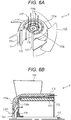
- a fan motor apparatus X having such a structure as illustrated in Fig. 6A (a perspective view) and Fig. 6B (a cross-sectional side view including a rotary shaft) is known.
- the fan motor apparatus X includes a rotor 114 fixed to a rotary shaft 117.
- the rotor 114 has, for example, a substantially L-shape in cross section.
- a hub 115 has been assembled to an outer side of the rotor 114.
- Blades 103 have been bonded to the hub 115.
- a magnet 113 is placed on an inner surface of the rotor 114.
- an air inlet port 114a is provided in such a manner as to take air into an area inside the rotor 114 from an opening 115b of a front surface 115a of the hub 115, avoiding a bushing 118. Consequently, a passage L101 that takes air into the motor from the outside is formed.
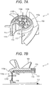
- Fig. 7A is a perspective view corresponding to Fig. 6A .
- Fig. 7A illustrates a structure including the rotor 114 further integrally molded with the integrally-molded product of the blades 103 and the hub 115.
- Fig. 7B is a cross-sectional side view corresponding to Fig. 6B .
- the structure illustrated in Figs. 7A and 7B can be compatible with an increase in rotational speed as described above.
- a fan motor apparatus Y has the structure including the rotor 114 integrated with the integrally-molded product of the blades 103 and the hub 115.
- the air inlet port 114a of the rotor 114 of the fan motor apparatus Y is exposed to the outside from the opening 115b of the front surface 115a of the hub 115, which facilitates the entrance of air into the motor (a passage L103).
- a new problem such as facilitating also the entrance of foreign matter.
- Integral molding of the rotor 114 and the blades 103 by supplying a resin material also to a top surface of the rotor 114 included in the structure illustrated in Figs. 7A and 7B is also under study. According to this method, the entrance of foreign matter from the air inlet port 114a on the top surface side can be prevented. However, this method results in blocking the passage of air into the motor. Hence, there arises a problem in that it becomes difficult to prevent heat from being generated in the motor.
- an object is to achieve compatibility between the prevention of the entrance of foreign matter into a fan motor apparatus and an improvement in internal cooling efficiency.
- a fan motor apparatus including: a blade; a rotary shaft; a hub; a rotor integrally molded with the blade, the rotor being fixed to the rotary shaft; and a protection cover including: a lid portion covering a top surface of the rotor; and an intake port configured to take air into the lid portion. Consequently, it is possible to prevent the entrance of foreign matter while ensuring an air passage into the rotor.
- the top surface may include an air hole, and the lid portion may be placed at a position that blocks the air hole.
- the lid portion may include a fixing hole portion configured to fix the protection cover to the rotary shaft, and the intake port may have been formed radially from the fixing hole portion toward an outer peripheral direction of the lid portion.
- the fan motor apparatus may further include a balance adjustment hole provided on a front surface on an intake side of the hub, the balance adjustment hole being configured to adjust balance for rotation of the blade.
- An outer peripheral portion of the protection cover may also serve as an inner wall of the balance adjustment hole.
- the intake port may be placed along an inner periphery of a front surface of the hub on the top surface of the protection cover.
- a plate-shaped portion of the top surface of the protection cover may be inclined downward below the intake port.
- a protection cover of a fan motor apparatus is configured to be attached to a fan motor apparatus including a blade integrally molded with a rotor fixed to a rotary shaft, the fan motor apparatus protection cover comprising a top surface, wherein the top surface includes: a lid portion configured to cover a top surface of the rotor; and an intake port.
- a member designated as a "protection cover” in the specification is also designated as a “cover” or a “protection cap.” These members described below are not limited by the designations to specific members.
- Fig. 1A is a perspective view illustrating a configuration example of a fan motor apparatus according to a first embodiment of the present disclosure.
- Fig. 1B is a cross-sectional side view illustrating a configuration example of the fan motor apparatus according to the embodiment, the cross-sectional side view including a rotary shaft of the fan motor apparatus.
- the left side in Fig. 1B corresponds to, for example, an intake side AR1.
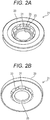
- Figs. 2A and 2B are perspective views illustrating a configuration example of a protection cover (rotor cap) used for the fan motor apparatus according to the embodiment.
- Fig. 2A is a perspective view as viewed from a front surface side.
- Fig. 2B is a perspective view as viewed from a rear surface side.
- a fan motor apparatus A includes a hub 5 to which blades (blades) 3 have been attached, a rotor 14 that has been formed on an inner surface of the hub 5, and a magnet 13 formed as an integral product on an inner surface of the rotor 14.
- the rotor 14 has been integrally formed with a rotary shaft 17.
- the rotor 14 has a substantially L-shape in cross-section and has a cup shape as viewed from a distal end direction of the rotary shaft 17.
- the rotor 14 is connected to the rotary shaft 17 via a rotor bushing 18.
- Figs. 1A and 1B illustration of a stator is omitted.
- the protection cover 21 that covers an exposed surface of a top surface being an intake-side end surface of the rotor 14 has been attached to the top surface.
- the protection cover 21 includes a lid-like member (lid portion) 23 of, for example, a disc shape.
- a fixing hole portion 25 for fixing the protection cover 21 to the rotary shaft 17 has been formed in, for example, a center portion of the lid portion 23.
- the lid portion 23 includes, for example, a single or a plurality of hole portions (intake ports) 31 formed radially from the fixing hole portion 25 toward the lid portion 23.
- the intake port 31 is divided into a plurality of sections by a plurality of support portions 33 extending from the fixing hole portion 25 toward an outer peripheral direction of the lid portion 23.
- the support portion 33 is inclined in the radial direction from the fixing hole portion 25 toward the outer peripheral direction of the lid portion 23.
- the support portions 33 may be placed parallel in a circumferential direction.
- an air hole 14a on the exposed surface has been formed on the top surface being the intake-side end surface of the rotor 14.
- the protection cover 21 has a shape that the lid portion 23 covers the air hole 14a on the exposed surface of the rotor 14 from a front surface side.
- the protection cover 21 hides the air hole 14a on the top surface of the rotor 14 with the lid portion 23 to prevent the entrance of foreign matter. Moreover, the intake port 31 is provided in a center portion of the protection cover 21. Thought was given to the cap shape so that it allows the formation of an air passage between the intake port 31 and the air hole 14a on the top surface of the rotor 14. Consequently, the inside of the fan motor apparatus A can be cooled.
- the plurality of intake ports 31 provided on the protection cover 21 ensures an air passage L1. The air passage L1 allows air to be easily taken into the rotor 14.
- the protection cover 21 is detachable from the rotor 14, for example, during the manufacturing process. However, the protection cover 21 is fixed to the rotor 14 in a final product.
- the protection cover 21 that covers the top surface of the rotor 14 is newly provided.
- the disc-shaped protection cover 21 including the air inlet port is attached to the rotor 14 integrally molded with the blades 3, which makes it possible to prevent the entrance of foreign matter while ensuring the air passage.
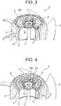
- Figs. 3 and 4 are perspective views illustrating a configuration example of the fan motor apparatus according to the embodiment.
- Figs. 3 and 4 are diagrams explaining a balance adjustment hole 43 provided on a front surface 41 on the intake side of the hub 5 to adjust balance for rotation of the blades.
- the disc-shaped protection cover 21 including the air inlet port has been attached to the rotor 14 integrally molded with the blades 3.
- an outer peripheral portion 21x of the disc-shaped protection cover 21 also serves as an inner wall forming a balance adjustment hole 43b on the front surface 41 of the hub 5.
- the outer peripheral portion 21x of the protection cover 21 serves as an inner boundary for delimiting the size of the balance adjustment hole 43b.
- the outer peripheral portion 21x of the protection cover 21 also serves as the inner wall of the balance adjustment hole 43b. This makes it possible to increase the size (the width in the radial direction) of the balance adjustment-purpose hole. Therefore, it becomes possible to reduce vibration in the fan motor apparatus.
- the protection cover according to the embodiment includes the air vent placed around the bushing. In other words, the structure that focuses on the prevention of the entrance of foreign matter is realized.
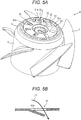
- Fig. 5A is a perspective view illustrating a configuration example of a fan motor apparatus according to a second embodiment of the present disclosure.
- Fig. 5B is a perspective view illustrating a configuration example of a protection cover (rotor cap) used for the fan motor apparatus according to the embodiment.
- Fig. 5C is a perspective view as viewed from a front surface side.
- Fig. 5D is a perspective view as viewed from a rear surface side.
- the structure of the protection cover is different from that of the first embodiment. The structure of the protection cover of the embodiment is described below.
- a plurality of hole portions (intake ports) 61 has been formed along an inner periphery of a front surface 41 of a hub 5 on a top surface 53 of a protection cover 51 according to the embodiment.
- a plate-shaped portion 61a of the top surface 53 is inclined downward below the intake port 61.
- an outer portion 51x of a lid portion 23 of the disc-shaped protection cover 51 also serves as part, here an inner side surface, of a balance adjustment-purpose hole 73. Accordingly, the size of the balance adjustment-purpose hole can be increased. Hence, it becomes possible to reduce vibration and increase productivity.
- the protection cover according to the embodiment has the structure of including the intake port radially placed on the top surface. Hence, a larger amount of ventilation can be obtained. Hence, the protection cover according to the embodiment is more suitable to improve internal cooling efficiency of the fan motor apparatus.
- the shape of the protection cover is not limited to the disc shape.
- the shape and the placement of the intake port can be designed as appropriate.
- the components of the present disclosure can be selected as appropriate.
- An embodiment including the selected configuration is also included in the embodiments.
- the present disclosure can be used for a fixing structure of a fan motor apparatus.
- a protection cover according to the embodiments of the present disclosure is a protection cover of a fan motor apparatus having a blade integrally molded with a rotor fixed to a rotary shaft, and may include: a lid portion covering an exposed surface of a top surface being an intake port-side end surface of the rotor; and an intake port on the lid portion.
Landscapes
- Engineering & Computer Science (AREA)
- Mechanical Engineering (AREA)
- General Engineering & Computer Science (AREA)
- Power Engineering (AREA)
- Physics & Mathematics (AREA)
- Thermal Sciences (AREA)
- Motor Or Generator Cooling System (AREA)
- Structures Of Non-Positive Displacement Pumps (AREA)
- Motor Or Generator Frames (AREA)
Applications Claiming Priority (1)
| Application Number | Priority Date | Filing Date | Title |
|---|---|---|---|
| JP2018045435A JP7105584B2 (ja) | 2018-03-13 | 2018-03-13 | ファンモータ装置およびファンモータ装置の保護カバー |
Publications (2)
| Publication Number | Publication Date |
|---|---|
| EP3540238A1 true EP3540238A1 (de) | 2019-09-18 |
| EP3540238B1 EP3540238B1 (de) | 2022-05-04 |
Family
ID=65801901
Family Applications (1)
| Application Number | Title | Priority Date | Filing Date |
|---|---|---|---|
| EP19162291.9A Active EP3540238B1 (de) | 2018-03-13 | 2019-03-12 | Lüftermotorvorrichtung mit schutzabdeckung |
Country Status (6)
| Country | Link |
|---|---|
| US (1) | US11041498B2 (de) |
| EP (1) | EP3540238B1 (de) |
| JP (1) | JP7105584B2 (de) |
| CN (1) | CN110277863B (de) |
| PH (1) | PH12019000129A1 (de) |
| TW (1) | TWI798377B (de) |
Cited By (1)
| Publication number | Priority date | Publication date | Assignee | Title |
|---|---|---|---|---|
| US12060887B2 (en) | 2020-02-13 | 2024-08-13 | Ebm-Papst St. Georgen Gmbh & Co. Kg | Fan with cover plate on the rotor bell |
Families Citing this family (10)
| Publication number | Priority date | Publication date | Assignee | Title |
|---|---|---|---|---|
| WO2017222055A1 (ja) * | 2016-06-24 | 2017-12-28 | 日本電産サーボ株式会社 | 送風装置 |
| JP2020060161A (ja) * | 2018-10-12 | 2020-04-16 | 株式会社ティラド | 軸流ファン |
| DE102018218988A1 (de) * | 2018-11-07 | 2020-05-07 | Hanon Systems Efp Deutschland Gmbh | Luftkühlung der Elektronik eines BLDC-Motors |
| CN113137384B (zh) * | 2020-01-16 | 2023-07-21 | 全亿大科技(佛山)有限公司 | 风扇及具有该风扇的电子装置 |
| IT202100016532A1 (it) * | 2021-06-23 | 2021-09-23 | General Cab S R L | Elettroventilatore assiale perfezionato per motori elettrici |
| DE102021214267A1 (de) | 2021-12-13 | 2023-06-15 | Ziehl-Abegg Se | Axial-, Diagonal- oder Radialventilator |
| KR102878447B1 (ko) * | 2021-12-30 | 2025-10-30 | 한온시스템 주식회사 | 고주파 소음 저감과 생산성 확보를 위한 팬 |
| US11967883B2 (en) | 2022-05-05 | 2024-04-23 | Hunter Fan Company | Ceiling fan |
| CN120312625A (zh) | 2024-01-12 | 2025-07-15 | 台达电子工业股份有限公司 | 风扇模块 |
| DE102024107338A1 (de) * | 2024-03-14 | 2025-09-18 | Brose Fahrzeugteile SE & Co. Kommanditgesellschaft, Würzburg | Lüfter |
Citations (6)
| Publication number | Priority date | Publication date | Assignee | Title |
|---|---|---|---|---|
| JPS552240U (de) * | 1978-06-21 | 1980-01-09 | ||
| JP4542479B2 (ja) | 2004-09-06 | 2010-09-15 | 台達電子工業股▲ふん▼有限公司 | モーターの強制熱放散構造 |
| DE202010013785U1 (de) * | 2009-10-03 | 2011-02-17 | Ebm-Papst St. Georgen Gmbh & Co. Kg | Diagonalventilator |
| US8217540B2 (en) * | 2009-01-27 | 2012-07-10 | Ebm-Papst Mulfingen Gmbh & Co. Kg | Electric motor with cooling ventilator effect |
| US20140010645A1 (en) * | 2012-07-05 | 2014-01-09 | Adda Corp. | Fan structure |
| JP2015139225A (ja) | 2014-01-20 | 2015-07-30 | 日本電産株式会社 | モータ |
Family Cites Families (13)
| Publication number | Priority date | Publication date | Assignee | Title |
|---|---|---|---|---|
| JPS552240A (en) | 1978-06-19 | 1980-01-09 | Matsushita Electric Industrial Co Ltd | Electrochromic display device |
| JPS6354893U (de) * | 1986-09-30 | 1988-04-13 | ||
| JPH08317589A (ja) * | 1995-05-15 | 1996-11-29 | Sankyo Seiki Mfg Co Ltd | 電動機 |
| US20040227416A1 (en) * | 2002-05-07 | 2004-11-18 | Shih-Ming Huang | Heat-dissipated mechanism for outer-rotor type brushless DC fan motor |
| JP3816843B2 (ja) | 2002-07-04 | 2006-08-30 | アスモ株式会社 | ブラシレスモータ |
| TWI279063B (en) * | 2005-06-10 | 2007-04-11 | Delta Electronics Inc | Fan and rotor thereof |
| CN201090471Y (zh) * | 2007-07-04 | 2008-07-23 | 鑫贺精密电子(东莞)有限公司 | 一体成型注塑磁环的节能散热风扇 |
| IT1396350B1 (it) * | 2009-10-26 | 2012-11-19 | Spal Automotive Srl | Ventilatore assiale |
| TWI464324B (zh) * | 2011-07-04 | 2014-12-11 | Sunonwealth Electr Mach Ind Co | 風扇 |
| ITTO20120765A1 (it) * | 2012-09-05 | 2014-03-06 | Johnson Electric Asti S R L | Gruppo di ventilazione, particolarmente per uno scambiatore di calore di un veicolo |
| CN103997160A (zh) * | 2013-02-15 | 2014-08-20 | 三星电机日本高科技株式会社 | 风扇电机 |
| CN104235064B (zh) | 2013-06-07 | 2018-01-26 | 台达电子工业股份有限公司 | 风扇及其叶轮 |
| KR101677650B1 (ko) * | 2014-12-23 | 2016-11-29 | 엘지전자 주식회사 | 팬-모터 조립체 및 이를 구비한 냉장고 |
-
2018
- 2018-03-13 JP JP2018045435A patent/JP7105584B2/ja active Active
-
2019
- 2019-03-08 US US16/296,341 patent/US11041498B2/en active Active
- 2019-03-11 TW TW108107971A patent/TWI798377B/zh active
- 2019-03-12 PH PH12019000129A patent/PH12019000129A1/en unknown
- 2019-03-12 EP EP19162291.9A patent/EP3540238B1/de active Active
- 2019-03-12 CN CN201910187481.4A patent/CN110277863B/zh active Active
Patent Citations (6)
| Publication number | Priority date | Publication date | Assignee | Title |
|---|---|---|---|---|
| JPS552240U (de) * | 1978-06-21 | 1980-01-09 | ||
| JP4542479B2 (ja) | 2004-09-06 | 2010-09-15 | 台達電子工業股▲ふん▼有限公司 | モーターの強制熱放散構造 |
| US8217540B2 (en) * | 2009-01-27 | 2012-07-10 | Ebm-Papst Mulfingen Gmbh & Co. Kg | Electric motor with cooling ventilator effect |
| DE202010013785U1 (de) * | 2009-10-03 | 2011-02-17 | Ebm-Papst St. Georgen Gmbh & Co. Kg | Diagonalventilator |
| US20140010645A1 (en) * | 2012-07-05 | 2014-01-09 | Adda Corp. | Fan structure |
| JP2015139225A (ja) | 2014-01-20 | 2015-07-30 | 日本電産株式会社 | モータ |
Cited By (2)
| Publication number | Priority date | Publication date | Assignee | Title |
|---|---|---|---|---|
| US12060887B2 (en) | 2020-02-13 | 2024-08-13 | Ebm-Papst St. Georgen Gmbh & Co. Kg | Fan with cover plate on the rotor bell |
| EP3865711B1 (de) * | 2020-02-13 | 2025-10-22 | Ebm-Papst St. Georgen Gmbh & Co. Kg | Ventilator mit abdeckscheibe an der rotorglocke |
Also Published As
| Publication number | Publication date |
|---|---|
| US20190285076A1 (en) | 2019-09-19 |
| JP2019161849A (ja) | 2019-09-19 |
| CN110277863B (zh) | 2024-06-11 |
| PH12019000129A1 (en) | 2019-09-23 |
| US11041498B2 (en) | 2021-06-22 |
| EP3540238B1 (de) | 2022-05-04 |
| CN110277863A (zh) | 2019-09-24 |
| TW201939855A (zh) | 2019-10-01 |
| TWI798377B (zh) | 2023-04-11 |
| JP7105584B2 (ja) | 2022-07-25 |
Similar Documents
| Publication | Publication Date | Title |
|---|---|---|
| US11041498B2 (en) | Fan motor apparatus and protection cover of fan motor apparatus | |
| CN205602145U (zh) | 电机、动力装置及使用该动力装置的无人飞行器 | |
| CN205901554U (zh) | 一种外转子电机 | |
| CN213402646U (zh) | 一种外转子电机系统 | |
| KR101792446B1 (ko) | 회전자 허브 조립체 및 전기 팬 | |
| CN106468283A (zh) | 离心风扇 | |
| JP2006217748A (ja) | ファンモータ | |
| US12218561B2 (en) | Electric machine assembly having a rotor frame to provide cooling | |
| US11808271B2 (en) | Axial fan | |
| JP4755177B2 (ja) | 自動車用回転電機 | |
| CN107709791B (zh) | 风扇和包括该风扇的通风组件 | |
| JP2004040935A (ja) | 電動ファンモータ装置 | |
| TWI921163B (zh) | 內循環散熱式風扇 | |
| US12362632B2 (en) | Electric machine assembly including housing assembly and fan positioned within housing assembly | |
| CN217789498U (zh) | 一种外转子电机 | |
| US20180262090A1 (en) | Electric motor and machine tool | |
| CN211155354U (zh) | 料理机 | |
| JP6925825B2 (ja) | モータ | |
| JPS6321177Y2 (de) | ||
| US20220235795A1 (en) | Fan and electric machine assembly and methods therefor | |
| US6483211B2 (en) | Turbine rotor sub-slot scoops | |
| JPS63129192A (ja) | 天井扇風機 | |
| JPS61108890A (ja) | 天井扇風機 | |
| TH68279A (th) | มอเตอร์ของพัดลมเพดาน |
Legal Events
| Date | Code | Title | Description |
|---|---|---|---|
| PUAI | Public reference made under article 153(3) epc to a published international application that has entered the european phase |
Free format text: ORIGINAL CODE: 0009012 |
|
| STAA | Information on the status of an ep patent application or granted ep patent |
Free format text: STATUS: THE APPLICATION HAS BEEN PUBLISHED |
|
| AK | Designated contracting states |
Kind code of ref document: A1 Designated state(s): AL AT BE BG CH CY CZ DE DK EE ES FI FR GB GR HR HU IE IS IT LI LT LU LV MC MK MT NL NO PL PT RO RS SE SI SK SM TR |
|
| AX | Request for extension of the european patent |
Extension state: BA ME |
|
| STAA | Information on the status of an ep patent application or granted ep patent |
Free format text: STATUS: REQUEST FOR EXAMINATION WAS MADE |
|
| 17P | Request for examination filed |
Effective date: 20200107 |
|
| RBV | Designated contracting states (corrected) |
Designated state(s): AL AT BE BG CH CY CZ DE DK EE ES FI FR GB GR HR HU IE IS IT LI LT LU LV MC MK MT NL NO PL PT RO RS SE SI SK SM TR |
|
| GRAP | Despatch of communication of intention to grant a patent |
Free format text: ORIGINAL CODE: EPIDOSNIGR1 |
|
| STAA | Information on the status of an ep patent application or granted ep patent |
Free format text: STATUS: GRANT OF PATENT IS INTENDED |
|
| RIC1 | Information provided on ipc code assigned before grant |
Ipc: H02K 1/32 20060101ALI20211101BHEP Ipc: H02K 5/10 20060101ALI20211101BHEP Ipc: H02K 9/06 20060101ALI20211101BHEP Ipc: H02K 7/14 20060101ALI20211101BHEP Ipc: F04D 29/32 20060101ALI20211101BHEP Ipc: F04D 25/08 20060101ALI20211101BHEP Ipc: F04D 25/06 20060101AFI20211101BHEP |
|
| INTG | Intention to grant announced |
Effective date: 20211125 |
|
| GRAS | Grant fee paid |
Free format text: ORIGINAL CODE: EPIDOSNIGR3 |
|
| GRAA | (expected) grant |
Free format text: ORIGINAL CODE: 0009210 |
|
| STAA | Information on the status of an ep patent application or granted ep patent |
Free format text: STATUS: THE PATENT HAS BEEN GRANTED |
|
| AK | Designated contracting states |
Kind code of ref document: B1 Designated state(s): AL AT BE BG CH CY CZ DE DK EE ES FI FR GB GR HR HU IE IS IT LI LT LU LV MC MK MT NL NO PL PT RO RS SE SI SK SM TR |
|
| REG | Reference to a national code |
Ref country code: GB Ref legal event code: FG4D |
|
| REG | Reference to a national code |
Ref country code: CH Ref legal event code: EP |
|
| REG | Reference to a national code |
Ref country code: AT Ref legal event code: REF Ref document number: 1489318 Country of ref document: AT Kind code of ref document: T Effective date: 20220515 |
|
| REG | Reference to a national code |
Ref country code: DE Ref legal event code: R096 Ref document number: 602019014313 Country of ref document: DE |
|
| REG | Reference to a national code |
Ref country code: IE Ref legal event code: FG4D |
|
| REG | Reference to a national code |
Ref country code: FI Ref legal event code: FGE |
|
| REG | Reference to a national code |
Ref country code: LT Ref legal event code: MG9D |
|
| REG | Reference to a national code |
Ref country code: NL Ref legal event code: MP Effective date: 20220504 |
|
| REG | Reference to a national code |
Ref country code: AT Ref legal event code: MK05 Ref document number: 1489318 Country of ref document: AT Kind code of ref document: T Effective date: 20220504 |
|
| PG25 | Lapsed in a contracting state [announced via postgrant information from national office to epo] |
Ref country code: SE Free format text: LAPSE BECAUSE OF FAILURE TO SUBMIT A TRANSLATION OF THE DESCRIPTION OR TO PAY THE FEE WITHIN THE PRESCRIBED TIME-LIMIT Effective date: 20220504 Ref country code: PT Free format text: LAPSE BECAUSE OF FAILURE TO SUBMIT A TRANSLATION OF THE DESCRIPTION OR TO PAY THE FEE WITHIN THE PRESCRIBED TIME-LIMIT Effective date: 20220905 Ref country code: NO Free format text: LAPSE BECAUSE OF FAILURE TO SUBMIT A TRANSLATION OF THE DESCRIPTION OR TO PAY THE FEE WITHIN THE PRESCRIBED TIME-LIMIT Effective date: 20220804 Ref country code: NL Free format text: LAPSE BECAUSE OF FAILURE TO SUBMIT A TRANSLATION OF THE DESCRIPTION OR TO PAY THE FEE WITHIN THE PRESCRIBED TIME-LIMIT Effective date: 20220504 Ref country code: LT Free format text: LAPSE BECAUSE OF FAILURE TO SUBMIT A TRANSLATION OF THE DESCRIPTION OR TO PAY THE FEE WITHIN THE PRESCRIBED TIME-LIMIT Effective date: 20220504 Ref country code: HR Free format text: LAPSE BECAUSE OF FAILURE TO SUBMIT A TRANSLATION OF THE DESCRIPTION OR TO PAY THE FEE WITHIN THE PRESCRIBED TIME-LIMIT Effective date: 20220504 Ref country code: GR Free format text: LAPSE BECAUSE OF FAILURE TO SUBMIT A TRANSLATION OF THE DESCRIPTION OR TO PAY THE FEE WITHIN THE PRESCRIBED TIME-LIMIT Effective date: 20220805 Ref country code: ES Free format text: LAPSE BECAUSE OF FAILURE TO SUBMIT A TRANSLATION OF THE DESCRIPTION OR TO PAY THE FEE WITHIN THE PRESCRIBED TIME-LIMIT Effective date: 20220504 Ref country code: BG Free format text: LAPSE BECAUSE OF FAILURE TO SUBMIT A TRANSLATION OF THE DESCRIPTION OR TO PAY THE FEE WITHIN THE PRESCRIBED TIME-LIMIT Effective date: 20220804 Ref country code: AT Free format text: LAPSE BECAUSE OF FAILURE TO SUBMIT A TRANSLATION OF THE DESCRIPTION OR TO PAY THE FEE WITHIN THE PRESCRIBED TIME-LIMIT Effective date: 20220504 |
|
| PG25 | Lapsed in a contracting state [announced via postgrant information from national office to epo] |
Ref country code: RS Free format text: LAPSE BECAUSE OF FAILURE TO SUBMIT A TRANSLATION OF THE DESCRIPTION OR TO PAY THE FEE WITHIN THE PRESCRIBED TIME-LIMIT Effective date: 20220504 Ref country code: PL Free format text: LAPSE BECAUSE OF FAILURE TO SUBMIT A TRANSLATION OF THE DESCRIPTION OR TO PAY THE FEE WITHIN THE PRESCRIBED TIME-LIMIT Effective date: 20220504 Ref country code: LV Free format text: LAPSE BECAUSE OF FAILURE TO SUBMIT A TRANSLATION OF THE DESCRIPTION OR TO PAY THE FEE WITHIN THE PRESCRIBED TIME-LIMIT Effective date: 20220504 Ref country code: IS Free format text: LAPSE BECAUSE OF FAILURE TO SUBMIT A TRANSLATION OF THE DESCRIPTION OR TO PAY THE FEE WITHIN THE PRESCRIBED TIME-LIMIT Effective date: 20220904 |
|
| PG25 | Lapsed in a contracting state [announced via postgrant information from national office to epo] |
Ref country code: SM Free format text: LAPSE BECAUSE OF FAILURE TO SUBMIT A TRANSLATION OF THE DESCRIPTION OR TO PAY THE FEE WITHIN THE PRESCRIBED TIME-LIMIT Effective date: 20220504 Ref country code: SK Free format text: LAPSE BECAUSE OF FAILURE TO SUBMIT A TRANSLATION OF THE DESCRIPTION OR TO PAY THE FEE WITHIN THE PRESCRIBED TIME-LIMIT Effective date: 20220504 Ref country code: RO Free format text: LAPSE BECAUSE OF FAILURE TO SUBMIT A TRANSLATION OF THE DESCRIPTION OR TO PAY THE FEE WITHIN THE PRESCRIBED TIME-LIMIT Effective date: 20220504 Ref country code: EE Free format text: LAPSE BECAUSE OF FAILURE TO SUBMIT A TRANSLATION OF THE DESCRIPTION OR TO PAY THE FEE WITHIN THE PRESCRIBED TIME-LIMIT Effective date: 20220504 Ref country code: DK Free format text: LAPSE BECAUSE OF FAILURE TO SUBMIT A TRANSLATION OF THE DESCRIPTION OR TO PAY THE FEE WITHIN THE PRESCRIBED TIME-LIMIT Effective date: 20220504 Ref country code: CZ Free format text: LAPSE BECAUSE OF FAILURE TO SUBMIT A TRANSLATION OF THE DESCRIPTION OR TO PAY THE FEE WITHIN THE PRESCRIBED TIME-LIMIT Effective date: 20220504 |
|
| REG | Reference to a national code |
Ref country code: DE Ref legal event code: R097 Ref document number: 602019014313 Country of ref document: DE |
|
| PLBE | No opposition filed within time limit |
Free format text: ORIGINAL CODE: 0009261 |
|
| STAA | Information on the status of an ep patent application or granted ep patent |
Free format text: STATUS: NO OPPOSITION FILED WITHIN TIME LIMIT |
|
| PG25 | Lapsed in a contracting state [announced via postgrant information from national office to epo] |
Ref country code: AL Free format text: LAPSE BECAUSE OF FAILURE TO SUBMIT A TRANSLATION OF THE DESCRIPTION OR TO PAY THE FEE WITHIN THE PRESCRIBED TIME-LIMIT Effective date: 20220504 |
|
| 26N | No opposition filed |
Effective date: 20230207 |
|
| PG25 | Lapsed in a contracting state [announced via postgrant information from national office to epo] |
Ref country code: SI Free format text: LAPSE BECAUSE OF FAILURE TO SUBMIT A TRANSLATION OF THE DESCRIPTION OR TO PAY THE FEE WITHIN THE PRESCRIBED TIME-LIMIT Effective date: 20220504 |
|
| PG25 | Lapsed in a contracting state [announced via postgrant information from national office to epo] |
Ref country code: MC Free format text: LAPSE BECAUSE OF FAILURE TO SUBMIT A TRANSLATION OF THE DESCRIPTION OR TO PAY THE FEE WITHIN THE PRESCRIBED TIME-LIMIT Effective date: 20220504 |
|
| REG | Reference to a national code |
Ref country code: CH Ref legal event code: PL |
|
| REG | Reference to a national code |
Ref country code: BE Ref legal event code: MM Effective date: 20230331 |
|
| PG25 | Lapsed in a contracting state [announced via postgrant information from national office to epo] |
Ref country code: LU Free format text: LAPSE BECAUSE OF NON-PAYMENT OF DUE FEES Effective date: 20230312 |
|
| REG | Reference to a national code |
Ref country code: IE Ref legal event code: MM4A |
|
| PG25 | Lapsed in a contracting state [announced via postgrant information from national office to epo] |
Ref country code: LI Free format text: LAPSE BECAUSE OF NON-PAYMENT OF DUE FEES Effective date: 20230331 Ref country code: IE Free format text: LAPSE BECAUSE OF NON-PAYMENT OF DUE FEES Effective date: 20230312 Ref country code: CH Free format text: LAPSE BECAUSE OF NON-PAYMENT OF DUE FEES Effective date: 20230331 |
|
| PG25 | Lapsed in a contracting state [announced via postgrant information from national office to epo] |
Ref country code: BE Free format text: LAPSE BECAUSE OF NON-PAYMENT OF DUE FEES Effective date: 20230331 |
|
| PG25 | Lapsed in a contracting state [announced via postgrant information from national office to epo] |
Ref country code: BG Free format text: LAPSE BECAUSE OF FAILURE TO SUBMIT A TRANSLATION OF THE DESCRIPTION OR TO PAY THE FEE WITHIN THE PRESCRIBED TIME-LIMIT Effective date: 20220504 |
|
| PG25 | Lapsed in a contracting state [announced via postgrant information from national office to epo] |
Ref country code: BG Free format text: LAPSE BECAUSE OF FAILURE TO SUBMIT A TRANSLATION OF THE DESCRIPTION OR TO PAY THE FEE WITHIN THE PRESCRIBED TIME-LIMIT Effective date: 20220504 |
|
| PG25 | Lapsed in a contracting state [announced via postgrant information from national office to epo] |
Ref country code: CY Free format text: LAPSE BECAUSE OF FAILURE TO SUBMIT A TRANSLATION OF THE DESCRIPTION OR TO PAY THE FEE WITHIN THE PRESCRIBED TIME-LIMIT; INVALID AB INITIO Effective date: 20190312 |
|
| PG25 | Lapsed in a contracting state [announced via postgrant information from national office to epo] |
Ref country code: HU Free format text: LAPSE BECAUSE OF FAILURE TO SUBMIT A TRANSLATION OF THE DESCRIPTION OR TO PAY THE FEE WITHIN THE PRESCRIBED TIME-LIMIT; INVALID AB INITIO Effective date: 20190312 |
|
| PG25 | Lapsed in a contracting state [announced via postgrant information from national office to epo] |
Ref country code: TR Free format text: LAPSE BECAUSE OF FAILURE TO SUBMIT A TRANSLATION OF THE DESCRIPTION OR TO PAY THE FEE WITHIN THE PRESCRIBED TIME-LIMIT Effective date: 20220504 |
|
| PGFP | Annual fee paid to national office [announced via postgrant information from national office to epo] |
Ref country code: GB Payment date: 20260324 Year of fee payment: 8 |
|
| PGFP | Annual fee paid to national office [announced via postgrant information from national office to epo] |
Ref country code: DE Payment date: 20260319 Year of fee payment: 8 |
|
| PGFP | Annual fee paid to national office [announced via postgrant information from national office to epo] |
Ref country code: FI Payment date: 20260323 Year of fee payment: 8 Ref country code: IT Payment date: 20260324 Year of fee payment: 8 |
|
| PGFP | Annual fee paid to national office [announced via postgrant information from national office to epo] |
Ref country code: FR Payment date: 20260320 Year of fee payment: 8 |