EP3540253A1 - Dispositif palier - Google Patents
Dispositif palier Download PDFInfo
- Publication number
- EP3540253A1 EP3540253A1 EP17870355.9A EP17870355A EP3540253A1 EP 3540253 A1 EP3540253 A1 EP 3540253A1 EP 17870355 A EP17870355 A EP 17870355A EP 3540253 A1 EP3540253 A1 EP 3540253A1
- Authority
- EP
- European Patent Office
- Prior art keywords
- bearing apparatus
- raceway surface
- axial direction
- ring
- fixed ring
- Prior art date
- Legal status (The legal status is an assumption and is not a legal conclusion. Google has not performed a legal analysis and makes no representation as to the accuracy of the status listed.)
- Granted
Links
Images


Classifications
-
- F—MECHANICAL ENGINEERING; LIGHTING; HEATING; WEAPONS; BLASTING
- F16—ENGINEERING ELEMENTS AND UNITS; GENERAL MEASURES FOR PRODUCING AND MAINTAINING EFFECTIVE FUNCTIONING OF MACHINES OR INSTALLATIONS; THERMAL INSULATION IN GENERAL
- F16C—SHAFTS; FLEXIBLE SHAFTS; ELEMENTS OR CRANKSHAFT MECHANISMS; ROTARY BODIES OTHER THAN GEARING ELEMENTS; BEARINGS
- F16C33/00—Parts of bearings; Special methods for making bearings or parts thereof
- F16C33/30—Parts of ball or roller bearings
- F16C33/66—Special parts or details in view of lubrication
- F16C33/6637—Special parts or details in view of lubrication with liquid lubricant
- F16C33/664—Retaining the liquid in or near the bearing
-
- F—MECHANICAL ENGINEERING; LIGHTING; HEATING; WEAPONS; BLASTING
- F16—ENGINEERING ELEMENTS AND UNITS; GENERAL MEASURES FOR PRODUCING AND MAINTAINING EFFECTIVE FUNCTIONING OF MACHINES OR INSTALLATIONS; THERMAL INSULATION IN GENERAL
- F16C—SHAFTS; FLEXIBLE SHAFTS; ELEMENTS OR CRANKSHAFT MECHANISMS; ROTARY BODIES OTHER THAN GEARING ELEMENTS; BEARINGS
- F16C19/00—Bearings with rolling contact, for exclusively rotary movement
- F16C19/02—Bearings with rolling contact, for exclusively rotary movement with bearing balls essentially of the same size in one or more circular rows
- F16C19/14—Bearings with rolling contact, for exclusively rotary movement with bearing balls essentially of the same size in one or more circular rows for both radial and axial load
- F16C19/16—Bearings with rolling contact, for exclusively rotary movement with bearing balls essentially of the same size in one or more circular rows for both radial and axial load with a single row of balls
-
- F—MECHANICAL ENGINEERING; LIGHTING; HEATING; WEAPONS; BLASTING
- F16—ENGINEERING ELEMENTS AND UNITS; GENERAL MEASURES FOR PRODUCING AND MAINTAINING EFFECTIVE FUNCTIONING OF MACHINES OR INSTALLATIONS; THERMAL INSULATION IN GENERAL
- F16C—SHAFTS; FLEXIBLE SHAFTS; ELEMENTS OR CRANKSHAFT MECHANISMS; ROTARY BODIES OTHER THAN GEARING ELEMENTS; BEARINGS
- F16C19/00—Bearings with rolling contact, for exclusively rotary movement
- F16C19/02—Bearings with rolling contact, for exclusively rotary movement with bearing balls essentially of the same size in one or more circular rows
- F16C19/14—Bearings with rolling contact, for exclusively rotary movement with bearing balls essentially of the same size in one or more circular rows for both radial and axial load
- F16C19/16—Bearings with rolling contact, for exclusively rotary movement with bearing balls essentially of the same size in one or more circular rows for both radial and axial load with a single row of balls
- F16C19/163—Bearings with rolling contact, for exclusively rotary movement with bearing balls essentially of the same size in one or more circular rows for both radial and axial load with a single row of balls with angular contact
-
- F—MECHANICAL ENGINEERING; LIGHTING; HEATING; WEAPONS; BLASTING
- F16—ENGINEERING ELEMENTS AND UNITS; GENERAL MEASURES FOR PRODUCING AND MAINTAINING EFFECTIVE FUNCTIONING OF MACHINES OR INSTALLATIONS; THERMAL INSULATION IN GENERAL
- F16C—SHAFTS; FLEXIBLE SHAFTS; ELEMENTS OR CRANKSHAFT MECHANISMS; ROTARY BODIES OTHER THAN GEARING ELEMENTS; BEARINGS
- F16C33/00—Parts of bearings; Special methods for making bearings or parts thereof
- F16C33/30—Parts of ball or roller bearings
- F16C33/58—Raceways; Race rings
-
- F—MECHANICAL ENGINEERING; LIGHTING; HEATING; WEAPONS; BLASTING
- F16—ENGINEERING ELEMENTS AND UNITS; GENERAL MEASURES FOR PRODUCING AND MAINTAINING EFFECTIVE FUNCTIONING OF MACHINES OR INSTALLATIONS; THERMAL INSULATION IN GENERAL
- F16C—SHAFTS; FLEXIBLE SHAFTS; ELEMENTS OR CRANKSHAFT MECHANISMS; ROTARY BODIES OTHER THAN GEARING ELEMENTS; BEARINGS
- F16C33/00—Parts of bearings; Special methods for making bearings or parts thereof
- F16C33/30—Parts of ball or roller bearings
- F16C33/58—Raceways; Race rings
- F16C33/583—Details of specific parts of races
-
- F—MECHANICAL ENGINEERING; LIGHTING; HEATING; WEAPONS; BLASTING
- F16—ENGINEERING ELEMENTS AND UNITS; GENERAL MEASURES FOR PRODUCING AND MAINTAINING EFFECTIVE FUNCTIONING OF MACHINES OR INSTALLATIONS; THERMAL INSULATION IN GENERAL
- F16C—SHAFTS; FLEXIBLE SHAFTS; ELEMENTS OR CRANKSHAFT MECHANISMS; ROTARY BODIES OTHER THAN GEARING ELEMENTS; BEARINGS
- F16C33/00—Parts of bearings; Special methods for making bearings or parts thereof
- F16C33/30—Parts of ball or roller bearings
- F16C33/66—Special parts or details in view of lubrication
- F16C33/6637—Special parts or details in view of lubrication with liquid lubricant
- F16C33/6659—Details of supply of the liquid to the bearing, e.g. passages or nozzles
-
- F—MECHANICAL ENGINEERING; LIGHTING; HEATING; WEAPONS; BLASTING
- F16—ENGINEERING ELEMENTS AND UNITS; GENERAL MEASURES FOR PRODUCING AND MAINTAINING EFFECTIVE FUNCTIONING OF MACHINES OR INSTALLATIONS; THERMAL INSULATION IN GENERAL
- F16C—SHAFTS; FLEXIBLE SHAFTS; ELEMENTS OR CRANKSHAFT MECHANISMS; ROTARY BODIES OTHER THAN GEARING ELEMENTS; BEARINGS
- F16C41/00—Other accessories, e.g. devices integrated in the bearing not relating to the bearing function as such
- F16C41/005—Fluid passages not relating to lubrication or cooling
-
- F—MECHANICAL ENGINEERING; LIGHTING; HEATING; WEAPONS; BLASTING
- F16—ENGINEERING ELEMENTS AND UNITS; GENERAL MEASURES FOR PRODUCING AND MAINTAINING EFFECTIVE FUNCTIONING OF MACHINES OR INSTALLATIONS; THERMAL INSULATION IN GENERAL
- F16N—LUBRICATING
- F16N29/00—Special means in lubricating arrangements or systems providing for the indication or detection of undesired conditions; Use of devices responsive to conditions in lubricating arrangements or systems
-
- F—MECHANICAL ENGINEERING; LIGHTING; HEATING; WEAPONS; BLASTING
- F16—ENGINEERING ELEMENTS AND UNITS; GENERAL MEASURES FOR PRODUCING AND MAINTAINING EFFECTIVE FUNCTIONING OF MACHINES OR INSTALLATIONS; THERMAL INSULATION IN GENERAL
- F16N—LUBRICATING
- F16N7/00—Arrangements for supplying oil or unspecified lubricant from a stationary reservoir or the equivalent in or on the machine or member to be lubricated
- F16N7/38—Arrangements for supplying oil or unspecified lubricant from a stationary reservoir or the equivalent in or on the machine or member to be lubricated with a separate pump; Central lubrication systems
-
- F—MECHANICAL ENGINEERING; LIGHTING; HEATING; WEAPONS; BLASTING
- F16—ENGINEERING ELEMENTS AND UNITS; GENERAL MEASURES FOR PRODUCING AND MAINTAINING EFFECTIVE FUNCTIONING OF MACHINES OR INSTALLATIONS; THERMAL INSULATION IN GENERAL
- F16C—SHAFTS; FLEXIBLE SHAFTS; ELEMENTS OR CRANKSHAFT MECHANISMS; ROTARY BODIES OTHER THAN GEARING ELEMENTS; BEARINGS
- F16C2361/00—Apparatus or articles in engineering in general
Definitions
- the present invention relates to a bearing apparatus, particularly, a bearing apparatus including an angular contact ball bearing and a supply portion configured to supply lubricating oil to the angular contact ball bearing.
- a bearing apparatus has been known in which an oil supply unit for supplying lubricating oil into a rolling bearing is incorporated in the rolling bearing.
- a bearing apparatus disclosed in Japanese Patent Laying-Open No. 2014-37879 includes a lubricating oil tank and a pump each disposed in a spacer adjacent to a bearing. In this bearing apparatus, lubricating oil can be stably supplied to the bearing for a long period of time by operating the pump intermittently.
- a main object of the present invention is to provide a bearing apparatus having a longer life than that of a conventional bearing apparatus.
- a bearing apparatus includes: an angular contact ball bearing including a fixed ring, a rotation ring, a plurality of rolling elements, and a cage, the fixed ring having a first raceway surface, the rotation ring being disposed to be separated from the first raceway surface in a radial direction of the fixed ring, the rotation ring having a second raceway surface, each of the plurality of rolling elements being disposed between the first raceway surface and the second raceway surface to have an contact angle with respect to each of the first raceway surface and the second raceway surface, the cage being configured to hold the plurality of rolling elements; a fixed ring spacer adjacent to the fixed ring in an axial direction of the angular contact ball bearing; a rotation ring spacer adjacent to the rotation ring in the axial direction, the rotation ring spacer being disposed to be separated from the fixed ring spacer in the radial direction; and a supply portion disposed between the fixed ring spacer and the rotation ring spacer, the supply portion being configured to supply
- a bearing apparatus having a longer life than that of a conventional bearing apparatus.
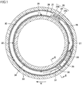
- Bearing apparatus 10 mainly includes an angular contact ball bearing 11 (see Fig. 2 ; hereinafter, simply referred to as "bearing 11"); bearing spacers 33, 34; and a lubricating oil supply unit 20 (see Fig. 2 ).
- angular contact ball bearing 11 mainly includes: an outer ring 13 serving as a fixed ring; an inner ring 14 serving as a rotation ring; a plurality of balls 15 each serving as a rolling element; and a cage 16.
- Outer ring 13 has a first raceway surface 13A.
- Inner ring 14 has a second raceway surface 14A.
- Each of the plurality of balls 15 is disposed between first raceway surface 13A and second raceway surface 14A to have a contact angle with respect to each of first raceway surface 13A and second raceway surface 14A.
- a side at which a contact angle line A of each ball 15 see Fig.
- bearing 11 when inner ring 14 is rotated under application of radial load and thrust load, a rolling track 13B of each ball 15 is formed on a partial region of first raceway surface 13A. Rolling track 13B is formed on first raceway surface 13A at a region that can be in contact with a rolling contact surface on contact angle line A.
- An inclination of contact angle line A relative to the axial direction of bearing 11 (hereinafter, simply referred to as "axial direction”) can be changed in accordance with use conditions such as preload and external load applied to bearing 11 and rotating speed.
- rolling track 13B has a width in a direction along first raceway surface 13A in a cross section perpendicular to the circumferential direction of bearing 11.
- First raceway surface 13A has a region not provided with rolling track 13B.
- Rolling track 13B is formed on the entire circumference of first raceway surface 13A in the above-described circumferential direction.
- Cage 16 holds the plurality of balls 15 at a certain interval in the circumferential direction of bearing 11.
- Cage 16 is disposed in a space formed between outer ring 13 and inner ring 14 so as to be separated from each of outer ring 13 and inner ring 14 in the radial direction.
- An end surface 16E of cage 16 in the above-described axial direction is formed at an axially inner side relative to the end surface (lateral surface) of outer ring 13 and the end surface (lateral surface) of inner ring 14 in the axial direction.
- outer ring 13 is provided with a recess 17 at least extending in the axial direction of the angular contact ball bearing.
- Recess 17 is formed as a through hole, for example.
- One end 17A of recess 17 in the axial direction faces the space formed between outer ring 13 and inner ring 14.
- One end 17A of recess 17 faces a clearance that is a portion of the space and that is formed between outer ring 13 and cage 16.
- Other end 17B of recess 17 in the axial direction is located at an outer side relative to the one end of recess 17 in the axial direction.
- Other end 17B of recess 17 is formed in the lateral surface of outer ring 13.
- the lateral surface of outer ring 13 refers to an end surface of outer ring 13 in the axial direction, the end surface facing a below-described outer ring spacer 33.
- a recess is formed in the lateral surface of outer ring 13
- other end 17B of recess 17 is formed in the lateral surface of outer ring 13 at a portion constituting the bottom of the foregoing recess formed in the lateral surface of outer ring 13.
- a hole axis B of recess 17 is formed to extend along one direction crossing the axial direction.
- An angle ⁇ of hole axis B of recess 17 relative to the axial direction is more than or equal to 100° and less than or equal to 170°, for example.
- Recess 17 includes: a first portion including one end 17A; and a second portion located at the outer ring spacer 33 side (upstream of a below-described supply path) relative to the first portion.
- the hole diameter of the first portion of recess 17 is smaller than the hole diameter of the second portion of recess 17.
- the respective hole diameters of the first portion and the second portion of recess 17 are set appropriately in accordance with a relation between an amount of discharge and a surface tension resulting from viscosity of base oil.
- the term "recess" refers to a structure depressed relative to a certain surface.
- An exemplary recess in the present invention is a through hole in which the recess extends to reach the other surface.
- Another exemplary recess in the present invention is a groove.
- a grease pocket 18 is formed adjacent to first raceway surface 13A at the rear side in the axial direction.
- Grease pocket 18 is formed as a groove portion in a shoulder portion 13C of outer ring 13 adjacent to first raceway surface 13A of outer ring 13 in the axial direction.
- Grease pocket 18 is formed along the circumferential direction of outer ring 13.
- An end portion of grease pocket 18 located at the inner side in the axial direction is connected to first raceway surface 13A.
- An end portion of grease pocket 18 located at the outer side in the axial direction is connected to the inner circumferential surface of shoulder portion 13C.
- the end portion of grease pocket 18 located at the outer side in the axial direction is formed at a position closer to first raceway surface 13A relative to end surface 16E of cage 16.
- One end 17A of recess 17 is formed inside grease pocket 18.
- One end 17A of recess 17 is formed in the end portion of grease pocket 18 located at the outer side in the axial direction, for example.
- an outline of one end 17A is in the form of a curve, for example.
- a grease pocket 18 is further formed adjacent to first raceway surface 13A at the front side in the axial direction, for example. That is, two grease pockets 18 are formed adjacent to first raceway surface 13A so as to sandwich first raceway surface 13A in the axial direction.
- Grease pocket 18 located at the front side relative to first raceway surface 13A has the same configuration as that of grease pocket 18 located at the rear side relative to first raceway surface 13A.
- Bearing spacers 33, 34 include an outer ring spacer 33 and an inner ring spacer 34.
- Outer ring spacer 33 is adjacent to outer ring 13 in the axial direction.
- the lateral surface of outer ring spacer 33 is in contact with the lateral surface of outer ring 13.
- Inner ring spacer 34 is adjacent to inner ring 14 in the axial direction.
- the lateral surface of inner ring spacer 34 is in contact with the lateral surface of inner ring 14. Desired grease is sealed in bearing 11 in advance.
- Lubricating oil supply unit 20 includes: a supply portion configured to supply lubricating oil to the above-described space between outer ring 13 and inner ring 14; and a power generator configured to generate electric power for operating the supply portion.
- lubricating oil supply unit 20 except for a portion of a below-described discharge tube 32, is disposed between outer ring spacer 33 and inner ring spacer 34. Between outer ring spacer 33 and inner ring spacer 34, an annular housing constituted of a housing main body 21 and a lid body 22 is formed.
- lubricating oil supply unit 20, except for the portion of below-described discharge tube 32 is disposed inside housing main body 21 and lid body 22.
- Lubricating oil supply unit 20 mainly includes power generator 25, a power supply circuit 26 including a charger, a control circuit 27, a drive circuit 28, a pump 29, and a lubricating oil tank 30, each of which is arranged in the circumferential direction.
- Control circuit 27, drive circuit 28, pump 29, lubricating oil tank 30, a suction tube 31, and discharge tube 32 constitutes the supply portion configured to supply the lubricating oil to the space between outer ring 13 and inner ring 14.
- Power generator 25 is provided to generate electric power for operating the supply portion of lubricating oil supply unit 20 and supply the electric power to the supply portion.
- Examples of power generator 25 include a power generator configured to generate electric power through a Seebeck effect.
- power generator 25 includes: a heat conductor 23a connected to outer ring spacer 33; a heat conductor 23b disposed with a clearance 36 being interposed between heat conductor 23b and inner ring spacer 34; and a thermoelectric element 24 (element employing the Seebeck effect of a Peltier device) disposed to connect between heat conductor 23a and heat conductor 23b and closely fixed to heat conductors 23a, 23b.
- Power generator 25 supplies electric power to lubricating oil supply unit 20 as follows.
- a rolling bearing apparatus is used as bearing apparatus 10 as shown in Fig. 1
- the temperatures of inner ring 14 and outer ring 13 are increased due to heat of friction with ball 15 (see Fig. 2 ).
- outer ring 13 is incorporated in the housing of the apparatus, so that the heat is radiated by heat conduction. Therefore, there occurs a temperature difference between inner ring 14 and outer ring 13 (the temperature of inner ring 14 is higher than the temperature of outer ring 13).
- Respective heats with the temperatures are conducted to heat conductors 23a, 23b.
- Heat conductors 23a, 23b are disposed to respectively extend through the inner circumferential surface and outer circumferential surface of housing main body 21.
- thermoelectric element 24 there occurs a temperature difference between the both end surfaces of thermoelectric element 24 disposed between heat conductor 23a (heat sink) connected to outer ring 13 with outer ring spacer 33 interposed therebetween and heat conductor 23b located at the inner ring spacer 34 side (inner ring 14 side). Accordingly, in thermoelectric element 24, electric power can be generated through the Seebeck effect. Since such a power generator 25 is used, it is not necessary to supply electric power to lubricating oil supply unit 20 from outside. Hence, no electric wire needs to be attached to bearing apparatus 10 in order to supply electric power from outside. Power generator 25 is connected to power supply circuit 26.
- Power supply circuit 26 is provided to store electric charges generated by power generator 25. Specifically, the charges are stored in a power storage device, such as a battery or a capacitor, included in power supply circuit 26. Power supply circuit 26 is connected to control circuit 27. Power supply circuit 26, which is electrically connected to drive circuit 28 and pump 29 via control circuit 27, is provided to supply electric power to these.
- control circuit 27 can obtain data regarding a state of supply of the lubricating oil in lubricating oil supply unit 20, and can output the data to outside of control circuit 27.
- Control circuit 27 includes: a program storage device configured to store a control program; and an arithmetic device (microcomputer) connected to the program storage device and configured to execute the control program.
- Various parameters regarding a normal rotation operation of pump 29 can be set in advance by control circuit 27, such as a time of starting to supply the lubricating oil to bearing 11, a timing (interval) of supply thereof, a time of driving pump 29 to supply the lubricating oil, and an amount of supply of the lubricating oil.
- Control circuit 27 is connected to drive circuit 28.
- Drive circuit 28 is a circuit for operating pump 29 such as a micro pump.
- Drive circuit 28 may include any sensor (such as a bearing temperature sensor, a bearing rotation sensor, a lubricating oil remaining amount sensor, a lubricating oil temperature sensor, or the like), for example.
- a signal from each of these sensors may be sent to an arithmetic device (microcomputer) of drive circuit 28 so as to automatically control pump 29 in accordance with the temperature and rotation state of bearing 11 to adjust the amount of supply of the lubricating oil.
- Pump 29 is a rotary pump such as a trochoid pump, for example. Pump 29 is controlled by control circuit 27 via drive circuit 28. Suction tube 31 and discharge tube 32 (nozzle) are connected to pump 29. Suction tube 31 is connected to a pouch of lubricating oil tank 30. Discharge tube 32 is configured to supply the lubricating oil from pump 29 to the inside of bearing 11. As shown in Fig. 2 , a discharge port (end portion opposite to a root portion connected to pump 29) of discharge tube 32 projects into the recess, which is formed in the lateral surface of outer ring 13, relative to the lateral surface of outer ring spacer 33 in the axial direction.
- the discharge port of discharge tube 32 is connected to other end 17B of recess 17 formed in the lateral surface of outer ring 13. Accordingly, the lubricating oil discharged from the discharge port of discharge tube 32 flows from other end 17B into recess 17, and flows out from one end 17A into grease pocket 18. It should be noted that the diameter of discharge tube 32 is appropriately set in accordance with the relation between the amount of discharge and the surface tension resulting from viscosity of the base oil.
- Lubricating oil tank 30 retains the same type of lubricating oil as the base oil of the grease sealed in bearing 11.
- Power generator 25, power supply circuit 26, control circuit 27, drive circuit 28, pump 29, and lubricating oil tank 30 are disposed side by side in the circumferential direction in housing main body 21.
- housing main body 21 has an open side opposite to bearing 11 and therefore has a U-like cross sectional shape.
- Lid body 22 closes the opening of housing main body 21 and is configured to be detachable from housing main body 21.
- Each of housing main body 21 and lid body 22 may be composed of any material such as a resin material, more preferably, a thermoplastic resin.
- a tap hole 35 (see Fig. 1 ) is formed in housing main body 21, and lid body 22 of the housing may be fixed to tap hole 35 using a screw.
- Housing main body 21 is fixed to outer ring spacer 33.
- Clearance 36 is formed between housing main body 21 and inner ring spacer 34.
- bearing apparatus 10 includes: angular contact ball bearing 11; and control circuit 27, drive circuit 28, pump 29, lubricating oil tank 30, suction tube 31, and discharge tube 32, which serve as the supply portion configured to supply lubricating oil to the space between outer ring 13 and inner ring 14.
- Bearing 11 includes: outer ring 13 serving as a fixed ring and having first raceway surface 13A; inner ring 14 serving as a rotation ring, inner ring 14 being disposed to be separated from first raceway surface 13A in the radial direction of outer ring 13, inner ring 14 having second raceway surface 14A; and the plurality of balls 15 disposed between first raceway surface 13A and second raceway surface 14A to have an contact angle with respect to each of first raceway surface 13A and second raceway surface 14A.
- Outer ring 13 is provided with recess 17.
- One end 17A of recess 17 faces the above-described space, specifically, a first space portion of the above-described space located at the outer ring 13 side relative to the outer diameter surface of cage 16.
- Other end 17B of recess 17 is located at the outer side relative to one end 17A of recess 17 in the axial direction of bearing 11.
- the supply portion is provided to supply lubricating oil to the space, particularly, the first space portion via recess 17.
- the above-described supply portion can supply lubricating oil to the space, particularly, the first space portion via recess 17.
- an air curtain is caused at a second space portion located at the inner ring 14 side relative to the outer diameter surface of cage 16 and located at the outer side relative to end surface 16E of cage 16 in the axial direction.
- the air curtain hinders the lubricating oil from flowing in the second space portion in the axial direction.
- an air curtain that can hinder the lubricating oil from flowing in the axial direction is not caused at the first space portion.
- the lubricating oil can be efficiently supplied to the first space portion of the space via one end 17A of recess 17 formed in outer ring 13 without an influence of the air curtain.
- the lubricating oil supplied to the first space portion can spread on first raceway surface 13A connected to the first space portion without an influence of the air curtain. That is, according to bearing apparatus 10, the lubricating oil can be supplied to first raceway surface 13A via the first space portion without an influence of the air curtain.
- bearing apparatus 10 has a longer life than that of a bearing apparatus in which the lubricating oil is supplied to the raceway surface via the above-described second space portion.
- bearing apparatus 10 further includes cage 16 configured to hold the plurality of balls 15.
- One end 17A of recess 17 is formed at the inner side relative to end surface 16E of cage 16 in the axial direction. That is, one end 17A faces a minute space portion of the first space portion located at the inner side relative to end surface 16E of cage 16 in the axial direction.
- the lubricating oil can be supplied to first raceway surface 13A via the minute space portion of the first space portion without an influence of the air curtain.
- a distance between one end 17A and first raceway surface 13A becomes shorter than that in the case where one end 17A is formed at the outer side relative to end surface 16E of cage 16 in the axial direction, i.e., in the case where one end 17A is formed at another space portion of the first space portion located at the outer side relative to the minute space portion in the axial direction.
- bearing apparatus 10 the lubricating oil can be supplied from recess 17 to first raceway surface 13A more promptly.
- bearing apparatus 10 has a longer life than a bearing apparatus 10 in which one end 17A is formed in outer ring 13 at the outer side relative to end surface 16E in the axial direction.
- one end 17A of recess 17 is formed in outer ring 13 at a region other than rolling track 13B of first raceway surface 13A. If one end 17A is formed in rolling track 13B, only a portion of the rolling contact surface of ball 15 is pressed against first raceway surface 13A to cause stress concentration, thus resulting in locally insufficient oil film, metal-to-metal contact, and excessive heat generation between outer ring 13 and ball 15. This may lead to surface damage or the like.
- one end 17A is formed in outer ring 13 at the region other than rolling track 13B of first raceway surface 13A. Hence, bearing 11 is suppressed from being damaged at an early stage as compared with a bearing apparatus 10 in which one end 17A is formed in rolling track 13B.
- outer ring 13 is provided with grease pocket 18 serving as a groove portion that is adjacent to first raceway surface 13A at the side (rear side) at which the contact angle is formed in the axial direction and that extends along the circumferential direction of outer ring 13.
- the grease can be sealed in grease pocket 18.
- one end 17A of recess 17 is formed in grease pocket 18. That is, recess 17 is connected to grease pocket 18. Accordingly, the lubricating oil supplied into the first space portion of the space from the supply portion via one end 17A can be first discharged into grease pocket 18 and can be then temporarily retained in grease pocket 18.
- the lubricating oil in grease pocket 18 appropriately spreads on first raceway surface 13A including rolling track 13B. Accordingly, according to bearing apparatus 10, insufficiency of oil film can be prevented more securely, whereby bearing apparatus 10 has a longer life than that of a bearing apparatus 10 in which grease pocket 18 is not formed.
- recess 17 is formed as a through hole formed in outer ring 13 serving as the fixed ring.
- One end 17A of recess 17 can be formed at a region close to rolling track 13B relative to end surface 16E of cage 16.
- the lubricating oil can be more securely supplied to first raceway surface 13A via recess 17.
- one end 17A of recess 17 is formed inside grease pocket 18 of outer ring 13, and other end 17B of recess 17 is formed in the lateral surface of outer ring 13. Hence, recess 17 does not cause the damage.
- Recess 17 is formed in the form of a straight line along a first direction. That is, hole axis B of recess 17 extends along the first direction. With this, recess 17 can be formed readily by perforation along the first direction, for example.
- the first direction has an angle ⁇ of more than or equal to 100° and less than or equal to 170° relative to the axial direction. With this, recess 17 can be formed readily to extend from the lateral surface of outer ring 13 into grease pocket 18.
- Bearing apparatus 10 further includes: outer ring spacer 33 serving as a fixed ring spacer and adjacent to outer ring 13 in the axial direction; inner ring spacer 34 adjacent to inner ring 14 in the axial direction and disposed to be separated from outer ring spacer 33 in the radial direction; and power generator 25 configured to generate electric power for operating the supply portion. Accordingly, bearing apparatus 10 does not need to externally receive electric power for operating the supply portion.
- the supply portion and power generator 25 constitute lubricating oil supply unit 20.
- Lubricating oil supply unit 20 is disposed mainly between outer ring spacer 33 and inner ring spacer 34. Accordingly, bearing apparatus 10 does not need to be provided with a space for placing lubricating oil supply unit 20 in bearing 11.
- the lubricating oil can be supplied to two bearings 11 disposed to sandwich outer ring spacer 33 and inner ring spacer 34 in the axial direction.
- Angular contact ball bearing 11 of bearing apparatus 10 includes outer ring 13 serving as the fixed ring and inner ring 14 serving as the rotation ring.
- Such a bearing apparatus 10 is suitable for a machine tool in which inner ring 14 is rotated at a high speed and preload and external load are applied to bearing 11, for example.
- one end 17A of recess 17 may not be formed in grease pocket 18.
- One end 17A of recess 17 may be formed in outer ring 13 at an appropriate position in the axial direction.
- one end 17A of recess 17 may be formed in outer ring 13 at the outer side relative to end surface 16E of cage 16 in the axial direction.
- the lubricating oil can be efficiently supplied from recess 17 to first raceway surface 13A via the first space portion without an influence of the air curtain.
- bearing apparatus 10 has a longer life than that of a bearing apparatus in which the lubricating oil is supplied to the inner side relative to the outer diameter surface of the cage in the radial direction.
- grease pocket 18 may not be formed in outer ring 13 and one end 17A of recess 17 may be formed in shoulder portion 13C adjacent to first raceway surface 13A. Also in this way, the lubricating oil can be efficiently supplied from recess 17 to first raceway surface 13A via the first space portion without an influence of the air curtain. As a result, bearing apparatus 10 has a longer life than that of a bearing apparatus in which the lubricating oil is supplied to the inner side relative to the outer diameter surface of the cage in the radial direction.
- recess 17 may be formed such that hole axis B is bent.
- recess 17 may be formed to have an L-like shape.
- Recess 17 may be constituted of: a portion having one end 17A and having a hole axis extending along the radial direction; and a portion having other end 17B and having a hole axis extending along the axial direction.
- recess 17 may be formed to have a U-like shape.
- other end 17B of recess 17 may not be formed in the lateral surface of outer ring 13.
- Other end 17B may be formed in the inner circumferential surface of outer ring 13 at the outer side relative to end surface 16E of cage 16 in the axial direction, for example.
- Discharge tube 32 may be formed such that discharge port 32A is connected to other end 17B.
- one end 17A of recess 17 may be formed in first raceway surface 13A located at the side (front side), at which the above-described contact angle is not formed, relative to rolling track 13B in the axial direction. Also in this way, the lubricating oil can be supplied efficiently from recess 17 to first raceway surface 13A via the first space portion without an influence of the air curtain. Moreover, since one end 17A is formed in first raceway surface 13A at the region other than rolling track 13B, damage caused by recess 17 is prevented in bearing apparatus 10. It should be noted that in this case, other end 17B of recess 17 may be formed in the end surface of outer ring 13 located at the front side in the axial direction.
- an extending distance of recess 17 from other end 17B to one end 17A can be shorter than that in the case where one end 17A and other end 17B are formed to sandwich contact angle line A in the axial direction. Accordingly, in bearing apparatus 10, the lubricating oil can be supplied from recess 17 to first raceway surface 13A promptly.
- angular contact ball bearing 11 of bearing apparatus 10 may include inner ring 14 serving as the fixed ring and outer ring 13 serving as the rotation ring.
- recess 17 is formed in inner ring 14 serving as the fixed ring.
- an air curtain can be caused at the outer side relative to the inner diameter surface of cage 16 facing inner ring 14 serving as the fixed ring in the radial direction and at the outer side relative to end surface 16E of cage 16 in the axial direction.
- an air curtain that can hinder the lubricating oil from flowing at least in the axial direction is not caused at a third space portion of the space located at the inner side in the radial direction relative to the inner diameter surface of cage 16 facing inner ring 14 serving as the fixed ring. Therefore, according to bearing apparatus 10 in which the lubricating oil is supplied to the third space portion via one end 17A of recess 17 formed in inner ring 14, hindrance of supply of the lubricating oil by the air curtain is prevented.
- the lubricating oil supplied to the third space portion can spread on first raceway surface 13A connected to the third space portion.
- bearing apparatus 10 has a longer life than a bearing apparatus in which the lubricating oil is supplied between cage 16 and outer ring 13 serving as the rotation ring in the radial direction.
- Fig. 3 to Fig. 6 shows a cross section perpendicular to the circumferential direction of bearing apparatus 10 as with Fig. 2 .
- bearing apparatus 110 includes basically the same configuration as that of bearing apparatus 10 according to the first embodiment, bearing apparatus 110 is different therefrom in that discharge port 32A of discharge tube 32 serving as a nozzle is disposed in bearing 11.
- a lubricating oil supply unit 120 of bearing apparatus 110 includes basically the same configuration as that of lubricating oil supply unit 20 according to the first embodiment, lubricating oil supply unit 120 is different therefrom in that discharge port 32A of discharge tube 32 is disposed in the above-described space of bearing 11.
- Fig. 7 shows a cross section perpendicular to the circumferential direction of bearing apparatus 110.
- bearing apparatus 110 includes angular contact ball bearing 11, outer ring spacer 33, inner ring spacer 34, and the above-described supply portion.
- Angular contact ball bearing 11 includes: outer ring 13 serving as a fixed ring and having first raceway surface 13A; inner ring 14 serving as a rotation ring, inner ring 14 being disposed to be separated from first raceway surface 13A in the radial direction of outer ring 13, inner ring 14 having second raceway surface 14A; a plurality of balls 15 disposed between first raceway surface 13A and second raceway surface 14A to have an contact angle with respect to each of first raceway surface 13A and second raceway surface 14A; and cage 16 configured to hold the plurality of balls 15.
- Outer ring spacer 33 is adjacent to outer ring 13 in the axial direction of angular contact ball bearing 11.
- Inner ring spacer 34 is adjacent to inner ring 14 in the axial direction and is disposed to be separated from outer ring spacer 33 in the radial direction.
- the supply portion is disposed between outer ring spacer 33 and inner ring spacer 34.
- the supply portion supplies the lubricating oil to the clearance between cage 16 and outer ring 13, i.e., the above-described first space portion.
- the supply portion includes discharge tube 32 serving as a nozzle.
- Discharge tube 32 has discharge port 32A disposed in the clearance, discharge port 32A being configured to discharge the lubricating oil. That is, discharge port 32A is formed at the inner side relative to end surface 16E of cage 16 in the axial direction.
- outer ring 13 in bearing apparatus 110 is provided with a nozzle insertion recess 117 in which a portion of discharge tube 32 is inserted.
- Nozzle insertion recess 117 includes basically the same configuration as that of recess 17 in bearing apparatus 10, and is different therefrom in that a portion of discharge tube 32 is inserted to nozzle insertion recess 117.
- One end 117A of nozzle insertion recess 117 in the axial direction faces the clearance between outer ring 13 and cage 16, i.e., the above-described minute space portion of the first space portion.
- Other end 117B of nozzle insertion recess 117 in the axial direction is located at the outer side relative to one end 117A in the axial direction.
- nozzle insertion recess 117 is formed in the end surface of shoulder portion 13C located at the outer side relative to one end 117A in the axial direction, for example.
- Nozzle insertion recess 117 is formed in shoulder portion 13C of outer ring 13 as a through hole.
- the hole axis of nozzle insertion recess 117 is along the axial direction, for example.
- the hole diameter of nozzle insertion recess 117 is longer than the outer diameter of discharge tube 32.
- outer ring 13 is provided with grease pocket 18 serving as a groove portion that is adjacent to first raceway surface 13A at the side at which the contact angle is formed in the axial direction and that is along the circumferential direction of outer ring 13.
- Discharge port 32A is disposed in grease pocket 18.
- bearing 11 includes outer ring 13 serving as the fixed ring and inner ring 14 serving as the rotation ring.
- center axis C of discharge tube 32 is along the hole axis of nozzle insertion recess 117, and is along the axial direction, for example.
- Discharge port 32A of discharge tube 32 is disposed at a position close to one end 117A relative to other end 117B of nozzle insertion recess 117, for example. That is, discharge port 32A is formed at the position close to first raceway surface 13A relative to end surface 16E of cage 16. A portion of discharge port 32A located at the cage 16 side projects into grease pocket 18, for example. That is, discharge port 32A is disposed in the minute space portion of the above-described first space portion.
- bearing apparatus 110 the lubricating oil discharged from discharge port 32A can be supplied from the inside of grease pocket 18 to first raceway surface 13 A without an influence of the air curtain. Hence, bearing apparatus 110 can exhibit the same effect as that of bearing apparatus 10.
- L2+r+L4 ⁇ L1 ⁇ L3 L2+r+L4 ⁇ L1 ⁇ L3, where L1 represents a distance between the center of discharge port 32A and the center of bearing 11 in the radial direction, L2 represents 1/2 (half) of the outer diameter of cage 16, L3 represents 1/2 (half) of the diameter of the bottom of the groove of first raceway surface 13A of outer ring 13, r represents 1/2 (half) of the outer diameter of discharge port 32A, and L4 represents a distance between outer ring 13 and the outer diameter surface of cage 16 in the radial direction.
- Distance L1 corresponds to the radius of a circle that centers on the center axis of bearing 11 and that passes through the center of discharge port 32A.
- Distance L4 corresponds to a distance between the inner circumferential surface of shoulder portion 13C of outer ring 13 and the outer diameter surface of cage 16 in the radial direction.
- Bearing apparatus 210 includes basically the same configuration as that of bearing apparatus 110 according to the second embodiment, and is different therefrom in that nozzle insertion recess 117 is formed as a groove, rather than a through hole.
- Nozzle insertion recess 117 is formed as a groove in outer ring 13, which serves as the fixed ring, at its inner circumferential surface facing inner ring 14 serving as the rotation ring.
- Fig. 9 shows a cross section perpendicular to the circumferential direction of bearing apparatus 210.
- nozzle insertion recess 117 is a groove formed to be recessed relative to the inner circumferential surface of shoulder portion 13C of outer ring 13.
- Nozzle insertion recess 117 is formed to extend along the axial direction. In the cross section perpendicular to the axial direction, the inner surface of nozzle insertion recess 117 forms a semicircular arc, for example.
- One end 117A of nozzle insertion recess 117 is formed inside grease pocket 18. That is, one end 117A is formed at the position close to first raceway surface 13A relative to end surface 16E of cage 16, and faces the minute space portion of the first space portion.
- Nozzle insertion recess 117 is connected to grease pocket 18.
- nozzle insertion recess 117 is formed in the end surface of shoulder portion 13C located at the outer side relative to one end 117A in the axial direction, for example.
- the hole axis of nozzle insertion recess 117 is along the axial direction, for example.
- Nozzle insertion recess 117 is provided to accommodate at least a portion of discharge tube 32.
- nozzle insertion recess 117 includes discharge port 32A of discharge tube 32 and is provided to accommodate a portion thereof located at the outer ring 13 side in the radial direction.
- center axis C of discharge tube 32 is along the hole axis of nozzle insertion recess 117, and is along the axial direction, for example.
- Discharge port 32A of discharge tube 32 is disposed at a position close to one end 117A relative to other end 117B of nozzle insertion recess 117, for example.
- a portion of discharge port 32A located at the cage 16 side projects into grease pocket 18, for example. That is, discharge port 32A is disposed in the minute space portion of the above-described first space portion.
- bearing apparatus 110 the lubricating oil discharged from discharge port 32A can be supplied to first raceway surface 13A including rolling track 13B without an influence of the air curtain. Accordingly, bearing apparatus 210 can exhibit the same effect as those of bearing apparatuses 10, 110.
- Each of bearing apparatuses 110, 210 can be modified in the same manner as the modification of bearing apparatus 10 described above.
- one end 117A of nozzle insertion recess 117 may not be formed inside grease pocket 18.
- One end 117A of nozzle insertion recess 117 may be formed at any position in the axial direction.
- one end 117A of nozzle insertion recess 117 may be formed at the outer side relative to end surface 16E of cage 16 in the axial direction.
- Grease pocket 18 may not be formed in outer ring 13 and one end 117A of nozzle insertion recess 117 may be formed in shoulder portion 13C adjacent to first raceway surface 13A.
- One end 117A of nozzle insertion recess 117 may be formed in first raceway surface 13A located at the side (front side), at which the above-described contact angle is not formed, relative to rolling track 13B in the axial direction.
- the hole axis of nozzle insertion recess 117 may be formed to be inclined relative to the axial direction.
- the present invention is applied particularly advantageously to a bearing apparatus including an angular contact ball bearing having a rotation ring configured to be rotated at a high speed.
Landscapes
- Engineering & Computer Science (AREA)
- General Engineering & Computer Science (AREA)
- Mechanical Engineering (AREA)
- Rolling Contact Bearings (AREA)
Applications Claiming Priority (2)
| Application Number | Priority Date | Filing Date | Title |
|---|---|---|---|
| JP2016219570A JP6906294B2 (ja) | 2016-11-10 | 2016-11-10 | 軸受装置 |
| PCT/JP2017/038742 WO2018088227A1 (fr) | 2016-11-10 | 2017-10-26 | Dispositif palier |
Publications (3)
| Publication Number | Publication Date |
|---|---|
| EP3540253A1 true EP3540253A1 (fr) | 2019-09-18 |
| EP3540253A4 EP3540253A4 (fr) | 2020-06-17 |
| EP3540253B1 EP3540253B1 (fr) | 2022-01-19 |
Family
ID=62109271
Family Applications (1)
| Application Number | Title | Priority Date | Filing Date |
|---|---|---|---|
| EP17870355.9A Active EP3540253B1 (fr) | 2016-11-10 | 2017-10-26 | Dispositif de palier |
Country Status (5)
| Country | Link |
|---|---|
| EP (1) | EP3540253B1 (fr) |
| JP (1) | JP6906294B2 (fr) |
| KR (1) | KR102477895B1 (fr) |
| CN (1) | CN109937309B (fr) |
| WO (1) | WO2018088227A1 (fr) |
Families Citing this family (3)
| Publication number | Priority date | Publication date | Assignee | Title |
|---|---|---|---|---|
| JP7411347B2 (ja) * | 2019-03-19 | 2024-01-11 | Ntn株式会社 | 潤滑油供給ユニットおよび軸受装置 |
| CN118728862A (zh) * | 2019-03-19 | 2024-10-01 | Ntn株式会社 | 润滑油供应单元和轴承装置 |
| JP7290530B2 (ja) * | 2019-09-26 | 2023-06-13 | Ntn株式会社 | 軸受装置および間座 |
Family Cites Families (10)
| Publication number | Priority date | Publication date | Assignee | Title |
|---|---|---|---|---|
| JP2008286270A (ja) * | 2007-05-16 | 2008-11-27 | Ntn Corp | ころ軸受の潤滑装置 |
| JP2009097553A (ja) * | 2007-10-15 | 2009-05-07 | Ntn Corp | 転がり軸受 |
| JP5233561B2 (ja) * | 2008-10-03 | 2013-07-10 | 株式会社ジェイテクト | 転がり軸受 |
| JP2010091067A (ja) * | 2008-10-10 | 2010-04-22 | Ntn Corp | アンギュラ玉軸受の潤滑構造 |
| JP2011106493A (ja) * | 2009-11-13 | 2011-06-02 | Ntn Corp | 転がり軸受装置 |
| JP2014031810A (ja) * | 2012-08-01 | 2014-02-20 | Ntn Corp | 転がり軸受装置 |
| JP2013076428A (ja) * | 2011-09-29 | 2013-04-25 | Ntn Corp | 軸受装置 |
| JP5989454B2 (ja) * | 2012-08-20 | 2016-09-07 | Ntn株式会社 | 転がり軸受装置 |
| JP2016023757A (ja) * | 2014-07-23 | 2016-02-08 | 株式会社ジェイテクト | 転がり軸受装置及び給油ユニット |
| JP6446887B2 (ja) * | 2014-07-23 | 2019-01-09 | 株式会社ジェイテクト | 転がり軸受装置及び給油ユニット |
-
2016
- 2016-11-10 JP JP2016219570A patent/JP6906294B2/ja active Active
-
2017
- 2017-10-26 EP EP17870355.9A patent/EP3540253B1/fr active Active
- 2017-10-26 CN CN201780069431.5A patent/CN109937309B/zh active Active
- 2017-10-26 WO PCT/JP2017/038742 patent/WO2018088227A1/fr not_active Ceased
- 2017-10-26 KR KR1020197016027A patent/KR102477895B1/ko active Active
Also Published As
| Publication number | Publication date |
|---|---|
| CN109937309B (zh) | 2021-11-12 |
| JP6906294B2 (ja) | 2021-07-21 |
| EP3540253B1 (fr) | 2022-01-19 |
| CN109937309A (zh) | 2019-06-25 |
| KR20190071819A (ko) | 2019-06-24 |
| JP2018076925A (ja) | 2018-05-17 |
| WO2018088227A1 (fr) | 2018-05-17 |
| EP3540253A4 (fr) | 2020-06-17 |
| KR102477895B1 (ko) | 2022-12-15 |
Similar Documents
| Publication | Publication Date | Title |
|---|---|---|
| EP2886893B1 (fr) | Dispositif de palier à roulement | |
| EP3540253B1 (fr) | Dispositif de palier | |
| KR102599685B1 (ko) | 베어링 장치 | |
| CN105896778B (zh) | 转子以及具备该转子的电动机 | |
| EP3540252B1 (fr) | Dispositif palier | |
| KR102657631B1 (ko) | 베어링 장치 및 기계 장치 | |
| KR102655632B1 (ko) | 베어링 장치 및 기계 장치 | |
| JP2009024822A (ja) | 玉軸受用冠型保持器 | |
| JP5908732B2 (ja) | 転がり軸受装置 | |
| KR102091916B1 (ko) | 냉각액 배출장치, 볼나사장치 | |
| ES2855975T3 (es) | Dispositivo de bombeo | |
| KR101690383B1 (ko) | 샤프트의 베어링 어셈블리 | |
| JP2018091455A (ja) | スラストころ軸受 | |
| JP2016161085A (ja) | アンギュラ玉軸受 |
Legal Events
| Date | Code | Title | Description |
|---|---|---|---|
| STAA | Information on the status of an ep patent application or granted ep patent |
Free format text: STATUS: THE INTERNATIONAL PUBLICATION HAS BEEN MADE |
|
| PUAI | Public reference made under article 153(3) epc to a published international application that has entered the european phase |
Free format text: ORIGINAL CODE: 0009012 |
|
| STAA | Information on the status of an ep patent application or granted ep patent |
Free format text: STATUS: REQUEST FOR EXAMINATION WAS MADE |
|
| 17P | Request for examination filed |
Effective date: 20190607 |
|
| AK | Designated contracting states |
Kind code of ref document: A1 Designated state(s): AL AT BE BG CH CY CZ DE DK EE ES FI FR GB GR HR HU IE IS IT LI LT LU LV MC MK MT NL NO PL PT RO RS SE SI SK SM TR |
|
| AX | Request for extension of the european patent |
Extension state: BA ME |
|
| DAV | Request for validation of the european patent (deleted) | ||
| DAX | Request for extension of the european patent (deleted) | ||
| A4 | Supplementary search report drawn up and despatched |
Effective date: 20200519 |
|
| RIC1 | Information provided on ipc code assigned before grant |
Ipc: F16C 33/66 20060101AFI20200513BHEP Ipc: F16C 19/16 20060101ALI20200513BHEP Ipc: F16N 29/00 20060101ALI20200513BHEP Ipc: F16N 7/38 20060101ALI20200513BHEP Ipc: F16C 33/58 20060101ALI20200513BHEP |
|
| GRAP | Despatch of communication of intention to grant a patent |
Free format text: ORIGINAL CODE: EPIDOSNIGR1 |
|
| STAA | Information on the status of an ep patent application or granted ep patent |
Free format text: STATUS: GRANT OF PATENT IS INTENDED |
|
| INTG | Intention to grant announced |
Effective date: 20210611 |
|
| GRAJ | Information related to disapproval of communication of intention to grant by the applicant or resumption of examination proceedings by the epo deleted |
Free format text: ORIGINAL CODE: EPIDOSDIGR1 |
|
| STAA | Information on the status of an ep patent application or granted ep patent |
Free format text: STATUS: REQUEST FOR EXAMINATION WAS MADE |
|
| GRAP | Despatch of communication of intention to grant a patent |
Free format text: ORIGINAL CODE: EPIDOSNIGR1 |
|
| STAA | Information on the status of an ep patent application or granted ep patent |
Free format text: STATUS: GRANT OF PATENT IS INTENDED |
|
| INTC | Intention to grant announced (deleted) | ||
| INTG | Intention to grant announced |
Effective date: 20211019 |
|
| GRAS | Grant fee paid |
Free format text: ORIGINAL CODE: EPIDOSNIGR3 |
|
| GRAA | (expected) grant |
Free format text: ORIGINAL CODE: 0009210 |
|
| STAA | Information on the status of an ep patent application or granted ep patent |
Free format text: STATUS: THE PATENT HAS BEEN GRANTED |
|
| AK | Designated contracting states |
Kind code of ref document: B1 Designated state(s): AL AT BE BG CH CY CZ DE DK EE ES FI FR GB GR HR HU IE IS IT LI LT LU LV MC MK MT NL NO PL PT RO RS SE SI SK SM TR |
|
| REG | Reference to a national code |
Ref country code: GB Ref legal event code: FG4D |
|
| REG | Reference to a national code |
Ref country code: CH Ref legal event code: EP |
|
| REG | Reference to a national code |
Ref country code: AT Ref legal event code: REF Ref document number: 1463955 Country of ref document: AT Kind code of ref document: T Effective date: 20220215 |
|
| REG | Reference to a national code |
Ref country code: IE Ref legal event code: FG4D |
|
| REG | Reference to a national code |
Ref country code: DE Ref legal event code: R096 Ref document number: 602017052602 Country of ref document: DE |
|
| REG | Reference to a national code |
Ref country code: LT Ref legal event code: MG9D |
|
| REG | Reference to a national code |
Ref country code: NL Ref legal event code: MP Effective date: 20220119 |
|
| REG | Reference to a national code |
Ref country code: AT Ref legal event code: MK05 Ref document number: 1463955 Country of ref document: AT Kind code of ref document: T Effective date: 20220119 |
|
| PG25 | Lapsed in a contracting state [announced via postgrant information from national office to epo] |
Ref country code: NL Free format text: LAPSE BECAUSE OF FAILURE TO SUBMIT A TRANSLATION OF THE DESCRIPTION OR TO PAY THE FEE WITHIN THE PRESCRIBED TIME-LIMIT Effective date: 20220119 |
|
| PG25 | Lapsed in a contracting state [announced via postgrant information from national office to epo] |
Ref country code: SE Free format text: LAPSE BECAUSE OF FAILURE TO SUBMIT A TRANSLATION OF THE DESCRIPTION OR TO PAY THE FEE WITHIN THE PRESCRIBED TIME-LIMIT Effective date: 20220119 Ref country code: RS Free format text: LAPSE BECAUSE OF FAILURE TO SUBMIT A TRANSLATION OF THE DESCRIPTION OR TO PAY THE FEE WITHIN THE PRESCRIBED TIME-LIMIT Effective date: 20220119 Ref country code: PT Free format text: LAPSE BECAUSE OF FAILURE TO SUBMIT A TRANSLATION OF THE DESCRIPTION OR TO PAY THE FEE WITHIN THE PRESCRIBED TIME-LIMIT Effective date: 20220519 Ref country code: NO Free format text: LAPSE BECAUSE OF FAILURE TO SUBMIT A TRANSLATION OF THE DESCRIPTION OR TO PAY THE FEE WITHIN THE PRESCRIBED TIME-LIMIT Effective date: 20220419 Ref country code: LT Free format text: LAPSE BECAUSE OF FAILURE TO SUBMIT A TRANSLATION OF THE DESCRIPTION OR TO PAY THE FEE WITHIN THE PRESCRIBED TIME-LIMIT Effective date: 20220119 Ref country code: HR Free format text: LAPSE BECAUSE OF FAILURE TO SUBMIT A TRANSLATION OF THE DESCRIPTION OR TO PAY THE FEE WITHIN THE PRESCRIBED TIME-LIMIT Effective date: 20220119 Ref country code: ES Free format text: LAPSE BECAUSE OF FAILURE TO SUBMIT A TRANSLATION OF THE DESCRIPTION OR TO PAY THE FEE WITHIN THE PRESCRIBED TIME-LIMIT Effective date: 20220119 Ref country code: BG Free format text: LAPSE BECAUSE OF FAILURE TO SUBMIT A TRANSLATION OF THE DESCRIPTION OR TO PAY THE FEE WITHIN THE PRESCRIBED TIME-LIMIT Effective date: 20220419 |
|
| PG25 | Lapsed in a contracting state [announced via postgrant information from national office to epo] |
Ref country code: PL Free format text: LAPSE BECAUSE OF FAILURE TO SUBMIT A TRANSLATION OF THE DESCRIPTION OR TO PAY THE FEE WITHIN THE PRESCRIBED TIME-LIMIT Effective date: 20220119 Ref country code: LV Free format text: LAPSE BECAUSE OF FAILURE TO SUBMIT A TRANSLATION OF THE DESCRIPTION OR TO PAY THE FEE WITHIN THE PRESCRIBED TIME-LIMIT Effective date: 20220119 Ref country code: GR Free format text: LAPSE BECAUSE OF FAILURE TO SUBMIT A TRANSLATION OF THE DESCRIPTION OR TO PAY THE FEE WITHIN THE PRESCRIBED TIME-LIMIT Effective date: 20220420 Ref country code: FI Free format text: LAPSE BECAUSE OF FAILURE TO SUBMIT A TRANSLATION OF THE DESCRIPTION OR TO PAY THE FEE WITHIN THE PRESCRIBED TIME-LIMIT Effective date: 20220119 Ref country code: AT Free format text: LAPSE BECAUSE OF FAILURE TO SUBMIT A TRANSLATION OF THE DESCRIPTION OR TO PAY THE FEE WITHIN THE PRESCRIBED TIME-LIMIT Effective date: 20220119 |
|
| PG25 | Lapsed in a contracting state [announced via postgrant information from national office to epo] |
Ref country code: IS Free format text: LAPSE BECAUSE OF FAILURE TO SUBMIT A TRANSLATION OF THE DESCRIPTION OR TO PAY THE FEE WITHIN THE PRESCRIBED TIME-LIMIT Effective date: 20220519 |
|
| REG | Reference to a national code |
Ref country code: DE Ref legal event code: R097 Ref document number: 602017052602 Country of ref document: DE |
|
| PG25 | Lapsed in a contracting state [announced via postgrant information from national office to epo] |
Ref country code: SM Free format text: LAPSE BECAUSE OF FAILURE TO SUBMIT A TRANSLATION OF THE DESCRIPTION OR TO PAY THE FEE WITHIN THE PRESCRIBED TIME-LIMIT Effective date: 20220119 Ref country code: SK Free format text: LAPSE BECAUSE OF FAILURE TO SUBMIT A TRANSLATION OF THE DESCRIPTION OR TO PAY THE FEE WITHIN THE PRESCRIBED TIME-LIMIT Effective date: 20220119 Ref country code: RO Free format text: LAPSE BECAUSE OF FAILURE TO SUBMIT A TRANSLATION OF THE DESCRIPTION OR TO PAY THE FEE WITHIN THE PRESCRIBED TIME-LIMIT Effective date: 20220119 Ref country code: EE Free format text: LAPSE BECAUSE OF FAILURE TO SUBMIT A TRANSLATION OF THE DESCRIPTION OR TO PAY THE FEE WITHIN THE PRESCRIBED TIME-LIMIT Effective date: 20220119 Ref country code: DK Free format text: LAPSE BECAUSE OF FAILURE TO SUBMIT A TRANSLATION OF THE DESCRIPTION OR TO PAY THE FEE WITHIN THE PRESCRIBED TIME-LIMIT Effective date: 20220119 Ref country code: CZ Free format text: LAPSE BECAUSE OF FAILURE TO SUBMIT A TRANSLATION OF THE DESCRIPTION OR TO PAY THE FEE WITHIN THE PRESCRIBED TIME-LIMIT Effective date: 20220119 |
|
| PLBE | No opposition filed within time limit |
Free format text: ORIGINAL CODE: 0009261 |
|
| STAA | Information on the status of an ep patent application or granted ep patent |
Free format text: STATUS: NO OPPOSITION FILED WITHIN TIME LIMIT |
|
| PG25 | Lapsed in a contracting state [announced via postgrant information from national office to epo] |
Ref country code: AL Free format text: LAPSE BECAUSE OF FAILURE TO SUBMIT A TRANSLATION OF THE DESCRIPTION OR TO PAY THE FEE WITHIN THE PRESCRIBED TIME-LIMIT Effective date: 20220119 |
|
| 26N | No opposition filed |
Effective date: 20221020 |
|
| PG25 | Lapsed in a contracting state [announced via postgrant information from national office to epo] |
Ref country code: SI Free format text: LAPSE BECAUSE OF FAILURE TO SUBMIT A TRANSLATION OF THE DESCRIPTION OR TO PAY THE FEE WITHIN THE PRESCRIBED TIME-LIMIT Effective date: 20220119 |
|
| PG25 | Lapsed in a contracting state [announced via postgrant information from national office to epo] |
Ref country code: MC Free format text: LAPSE BECAUSE OF FAILURE TO SUBMIT A TRANSLATION OF THE DESCRIPTION OR TO PAY THE FEE WITHIN THE PRESCRIBED TIME-LIMIT Effective date: 20220119 |
|
| REG | Reference to a national code |
Ref country code: CH Ref legal event code: PL |
|
| REG | Reference to a national code |
Ref country code: BE Ref legal event code: MM Effective date: 20221031 |
|
| GBPC | Gb: european patent ceased through non-payment of renewal fee |
Effective date: 20221026 |
|
| PG25 | Lapsed in a contracting state [announced via postgrant information from national office to epo] |
Ref country code: LU Free format text: LAPSE BECAUSE OF NON-PAYMENT OF DUE FEES Effective date: 20221026 |
|
| PG25 | Lapsed in a contracting state [announced via postgrant information from national office to epo] |
Ref country code: LI Free format text: LAPSE BECAUSE OF NON-PAYMENT OF DUE FEES Effective date: 20221031 Ref country code: IT Free format text: LAPSE BECAUSE OF FAILURE TO SUBMIT A TRANSLATION OF THE DESCRIPTION OR TO PAY THE FEE WITHIN THE PRESCRIBED TIME-LIMIT Effective date: 20220119 Ref country code: FR Free format text: LAPSE BECAUSE OF NON-PAYMENT OF DUE FEES Effective date: 20221031 Ref country code: CH Free format text: LAPSE BECAUSE OF NON-PAYMENT OF DUE FEES Effective date: 20221031 |
|
| PG25 | Lapsed in a contracting state [announced via postgrant information from national office to epo] |
Ref country code: BE Free format text: LAPSE BECAUSE OF NON-PAYMENT OF DUE FEES Effective date: 20221031 |
|
| PG25 | Lapsed in a contracting state [announced via postgrant information from national office to epo] |
Ref country code: IE Free format text: LAPSE BECAUSE OF NON-PAYMENT OF DUE FEES Effective date: 20221026 Ref country code: GB Free format text: LAPSE BECAUSE OF NON-PAYMENT OF DUE FEES Effective date: 20221026 |
|
| PG25 | Lapsed in a contracting state [announced via postgrant information from national office to epo] |
Ref country code: HU Free format text: LAPSE BECAUSE OF FAILURE TO SUBMIT A TRANSLATION OF THE DESCRIPTION OR TO PAY THE FEE WITHIN THE PRESCRIBED TIME-LIMIT; INVALID AB INITIO Effective date: 20171026 |
|
| PG25 | Lapsed in a contracting state [announced via postgrant information from national office to epo] |
Ref country code: CY Free format text: LAPSE BECAUSE OF FAILURE TO SUBMIT A TRANSLATION OF THE DESCRIPTION OR TO PAY THE FEE WITHIN THE PRESCRIBED TIME-LIMIT Effective date: 20220119 |
|
| PG25 | Lapsed in a contracting state [announced via postgrant information from national office to epo] |
Ref country code: MK Free format text: LAPSE BECAUSE OF FAILURE TO SUBMIT A TRANSLATION OF THE DESCRIPTION OR TO PAY THE FEE WITHIN THE PRESCRIBED TIME-LIMIT Effective date: 20220119 |
|
| PG25 | Lapsed in a contracting state [announced via postgrant information from national office to epo] |
Ref country code: MT Free format text: LAPSE BECAUSE OF FAILURE TO SUBMIT A TRANSLATION OF THE DESCRIPTION OR TO PAY THE FEE WITHIN THE PRESCRIBED TIME-LIMIT Effective date: 20220119 |
|
| PG25 | Lapsed in a contracting state [announced via postgrant information from national office to epo] |
Ref country code: TR Free format text: LAPSE BECAUSE OF FAILURE TO SUBMIT A TRANSLATION OF THE DESCRIPTION OR TO PAY THE FEE WITHIN THE PRESCRIBED TIME-LIMIT Effective date: 20220119 |
|
| PGFP | Annual fee paid to national office [announced via postgrant information from national office to epo] |
Ref country code: DE Payment date: 20250902 Year of fee payment: 9 |