EP3540328B1 - Ablaufeinrichtung - Google Patents
Ablaufeinrichtung Download PDFInfo
- Publication number
- EP3540328B1 EP3540328B1 EP19162042.6A EP19162042A EP3540328B1 EP 3540328 B1 EP3540328 B1 EP 3540328B1 EP 19162042 A EP19162042 A EP 19162042A EP 3540328 B1 EP3540328 B1 EP 3540328B1
- Authority
- EP
- European Patent Office
- Prior art keywords
- section
- pipe section
- housing
- pipe
- drain
- Prior art date
- Legal status (The legal status is an assumption and is not a legal conclusion. Google has not performed a legal analysis and makes no representation as to the accuracy of the status listed.)
- Active
Links
Images




Classifications
-
- F—MECHANICAL ENGINEERING; LIGHTING; HEATING; WEAPONS; BLASTING
- F24—HEATING; RANGES; VENTILATING
- F24H—FLUID HEATERS, e.g. WATER OR AIR HEATERS, HAVING HEAT-GENERATING MEANS, e.g. HEAT PUMPS, IN GENERAL
- F24H8/00—Fluid heaters characterised by means for extracting latent heat from flue gases by means of condensation
- F24H8/006—Means for removing condensate from the heater
-
- F—MECHANICAL ENGINEERING; LIGHTING; HEATING; WEAPONS; BLASTING
- F24—HEATING; RANGES; VENTILATING
- F24F—AIR-CONDITIONING; AIR-HUMIDIFICATION; VENTILATION; USE OF AIR CURRENTS FOR SCREENING
- F24F13/00—Details common to, or for air-conditioning, air-humidification, ventilation or use of air currents for screening
- F24F13/22—Means for preventing condensation or evacuating condensate
- F24F13/222—Means for preventing condensation or evacuating condensate for evacuating condensate
-
- E—FIXED CONSTRUCTIONS
- E03—WATER SUPPLY; SEWERAGE
- E03C—DOMESTIC PLUMBING INSTALLATIONS FOR FRESH WATER OR WASTE WATER; SINKS
- E03C1/00—Domestic plumbing installations for fresh water or waste water; Sinks
- E03C1/12—Plumbing installations for waste water; Basins or fountains connected thereto; Sinks
- E03C1/28—Odour seals
-
- E—FIXED CONSTRUCTIONS
- E03—WATER SUPPLY; SEWERAGE
- E03F—SEWERS; CESSPOOLS
- E03F5/00—Sewerage structures
- E03F5/04—Gullies inlets, road sinks, floor drains with or without odour seals or sediment traps
- E03F5/0407—Floor drains for indoor use
-
- F—MECHANICAL ENGINEERING; LIGHTING; HEATING; WEAPONS; BLASTING
- F25—REFRIGERATION OR COOLING; COMBINED HEATING AND REFRIGERATION SYSTEMS; HEAT PUMP SYSTEMS; MANUFACTURE OR STORAGE OF ICE; LIQUEFACTION SOLIDIFICATION OF GASES
- F25B—REFRIGERATION MACHINES, PLANTS OR SYSTEMS; COMBINED HEATING AND REFRIGERATION SYSTEMS; HEAT PUMP SYSTEMS
- F25B30/00—Heat pumps
- F25B30/02—Heat pumps of the compression type
-
- Y—GENERAL TAGGING OF NEW TECHNOLOGICAL DEVELOPMENTS; GENERAL TAGGING OF CROSS-SECTIONAL TECHNOLOGIES SPANNING OVER SEVERAL SECTIONS OF THE IPC; TECHNICAL SUBJECTS COVERED BY FORMER USPC CROSS-REFERENCE ART COLLECTIONS [XRACs] AND DIGESTS
- Y02—TECHNOLOGIES OR APPLICATIONS FOR MITIGATION OR ADAPTATION AGAINST CLIMATE CHANGE
- Y02B—CLIMATE CHANGE MITIGATION TECHNOLOGIES RELATED TO BUILDINGS, e.g. HOUSING, HOUSE APPLIANCES OR RELATED END-USER APPLICATIONS
- Y02B30/00—Energy efficient heating, ventilation or air conditioning [HVAC]
Definitions
- the invention relates to a drain device according to the preamble of claim 1 and a heat pump and / or ventilation device, the condensate drain of which is connected to such a drain device according to claim 13.
- Drainage devices are used in the prior art to transfer, for example, condensate from a heat pump and / or ventilation device into a drainage duct system.
- These heat pump and / or ventilation devices are used for temperature control and / or controlled building ventilation (for example also referred to as controlled living space ventilation) and are often installed directly on the base plate so that they have a very low condensate drain.
- the condensate drain serves to discharge collected condensate, which accumulates in particular on the negative pressure side of the heat pump device on cold components or on heat exchangers of the ventilation device.
- the condensate drain is usually only just above the base plate.
- JP 2017 201079 A a funnel-shaped floor drain with a drain arranged laterally on the funnel-shaped housing is known.
- EP 0 807 721 A2 discloses a drain fitting for shower and bath tubs for basements, balconies, patios. This has a pot-shaped housing, from which a drain pipe opens out on the side.
- a drain device with a spherical housing into which a dip tube opens and which has a drain arranged on the side.
- the object of the invention is therefore to develop a drain device and a heat pump and / or ventilation device which are simple and inexpensive to install with regard to the condensate drainage and which allow a permanently safe drainage of condensate even in the case of small pipe gradients in order to avoid water damage.
- the drain device is preferably compatible and can be retrofitted to a large number of heat pump and / or ventilation system models, should form an odor trap, and should be easy to secure against backflow so that water damage caused by backflow is also avoided.
- the invention relates to a drain device with a housing designed as a collecting container with a housing bottom arranged geodetically at the bottom, an inlet opening into the housing and a drain arranged geodetically at the side of the housing, the outlet having a passage opening which forms a geodetically located overflow vertex which is arranged higher is than the case back.
- the latter can be used in particular to define a level of accumulation in the housing for a fluid between the housing base and the overflow apex.
- the inlet has an inlet opening which opens into the housing and is geodetically arranged lower than the overflow vertex. This defines in particular a fluid-based odor trap height between the inlet opening and the overflow apex in the housing.
- the drain has a horizontally running drain pipe section with a pipe cross-sectional area which (in particular as a whole) is arranged higher than the housing base, the overflow vertex being arranged geodetically above an end of the pipe cross-sectional area located geodetically below. In this way, it can be achieved in particular that the accumulation height is higher than this lower end of the pipe cross-sectional area.
- An advantage of this configuration is that although the drain pipe section can be placed quite deep on the housing, the accumulation height is shifted upwards by means of the overflow vertex. This means that the drain device can be constructed flat and a large fluid column for the odor trap is nevertheless achieved. Compared to a siphon designed as a pipe bend, a comparatively large flat housing can also be provided, so that a reliable odor trap is achieved for a relatively long time in the idle time of the heat pump and / or ventilation device. A comparatively large volume of fluid is available, which would have to evaporate first. With the exception of the inlet and the outlet, the housing should be fluid-tight. This avoids evaporation and even in the case of a backflow no fluid escapes, at least in the area of the drain device. All directions with regard to geodesy relate to an orientation in the assembly position intended for operation.
- the pipe cross-sectional area of the horizontally running drain pipe section has a geodetically vertical extension, the overflow vertex preferably being arranged in the geodetically arranged 2/3 area of the vertical extension. With that lies the Overflow vertex high and the passage opening can still have a quite large cross-sectional area. It is preferable that the passage opening extends geodetically at least substantially to the upper end of the vertical extent of the pipe cross-sectional area. The available height is thus fully utilized, the drain device can be designed flat and can be secured against backflow in a simple manner.
- the housing is made of plastic, preferably a plastic from the group consisting of polyethylene (PE) or polypropylene (PP), polyvinyl chloride (PVC), styrene copolymers (ABS / ASA) and polyester resin (UP).
- PE polyethylene
- PP polypropylene
- PVC polyvinyl chloride
- ABS / ASA styrene copolymers
- UP polyester resin
- the inlet consists of plastic, preferably of a plastic from the group consisting of polyethylene (PE) or polypropylene (PP), polyvinyl chloride (PVC), styrene copolymers (ABS / ASA) and polyester resin (UP).
- PE polyethylene
- PP polypropylene
- PVC polyvinyl chloride
- ABS / ASA styrene copolymers
- UP polyester resin
- the horizontal drain pipe section can consist of plastic, preferably of a plastic from the group consisting of polyethylene (PE) or polypropylene (PP), polyvinyl chloride (PVC), styrene copolymers (ABS / ASA) and polyester resin (UP). These plastics have proven themselves for cables in building technology.
- PE polyethylene
- PP polypropylene
- PVC polyvinyl chloride
- ABS / ASA styrene copolymers
- UP polyester resin
- the passage opening of the drain is formed in a diaphragm.
- the material that can be used here is that the cover is made of plastic, preferably a plastic from the group consisting of polyethylene (PE) or polypropylene (PP), polyvinyl chloride (PVC), styrene copolymers (ABS / ASA) and polyester resin (UP).
- PE polyethylene
- PP polypropylene
- PVC polyvinyl chloride
- ABS / ASA styrene copolymers
- UP polyester resin
- a variant can be implemented in a particularly space-saving manner in which the diaphragm is designed to be flat on the side pointing in the direction of the housing.
- the cover sits in the horizontally running drain pipe section.
- the panel can be arranged correspondingly small and space-saving.
- an embodiment can be implemented according to which the panel coming from the direction of the housing is inserted into the horizontally extending drain pipe section. After from used inside, e.g. by manufacturer assembly, a craftsman will no longer change their position and a source of assembly errors is avoided.
- the diaphragm is formed by a cover, the passage opening being formed in the cover.
- a cover can be easily mounted in its seat, which is to be formed on the housing and / or the horizontal drain pipe section for this purpose.
- a high level of compatibility of the drain device without special solutions by the fitter is achieved if the horizontal drain pipe section is from the group DN 40, DN 50, DN 70, DN 80, DN 110 and DN 125.
- An embodiment of the drain pipe section as a socket is also advantageous, because usually a sleeve will be available to connect the drainage pipe.
- the drain device according to the invention is particularly inexpensive to produce because it has a (preferably standardized) transition pipe piece which forms a reduction from a first pipe section with a larger pipe cross section to a second pipe section with a smaller pipe cross section, the housing being composed of the first pipe section and a closure element, which closes the free end of the first pipe section, is formed, and wherein the horizontally extending drain pipe section is formed by the second pipe section.
- a transition pipe piece which forms a reduction from a first pipe section with a larger pipe cross section to a second pipe section with a smaller pipe cross section
- the housing being composed of the first pipe section and a closure element, which closes the free end of the first pipe section, is formed, and wherein the horizontally extending drain pipe section is formed by the second pipe section.
- Such transition pipe pieces exist in fact in quite a large number of variants as finished parts and accordingly no special tools are necessary for the production of the housing and the horizontally running drain pipe section. Even the closure elements exist as finished goods.
- the first and the second pipe section of the transition pipe section are preferably aligned identically, in particular aligned axially, and aligned horizontally in the installed position.
- the second pipe section is also preferably offset from the first pipe section. In this case, an offset is preferred in which the second pipe section is arranged geodetically higher than the first pipe section.
- the tube cross section of the second tube section is still completely or at least half in the horizontal projection of the tube cross section of the first tube section.
- a transition pipe piece is preferably used in which a reduction section, in particular a reduction section, is arranged between the first and second pipe sections funnel-shaped reduction section. This forms a slower cross-section transition.
- the transition pipe piece consists of plastic, preferably of a plastic from the group consisting of polyethylene (PE) or polypropylene (PP), polyvinyl chloride (PVC), styrene copolymers (ABS / ASA) and polyester resin (UP).
- PE polyethylene
- PP polypropylene
- PVC polyvinyl chloride
- ABS / ASA styrene copolymers
- UP polyester resin
- the first pipe section is from the group DN 70, DN 80, DN 100, DN 110, DN 125 and DN 160. Accordingly, a prefabricated part can be used as a transition pipe piece for the drain device.
- the inlet has an immersion tube which projects geodetically within the housing to below the overflow vertex and forms the inlet opening at the end.
- the dip tube preferably consists of plastic, in particular of a plastic from the group consisting of polyethylene (PE) or polypropylene (PP), polyvinyl chloride (PVC), styrene copolymers (ABS / ASA) and polyester resin (UP).
- PE polyethylene
- PP polypropylene
- PVC polyvinyl chloride
- ABS / ASA styrene copolymers
- UP polyester resin
- the immersion tube can protrude above the housing base through the housing into its interior, preferably geodetically from above. The passage of the dip tube through the housing, which tends to leak, is thus arranged above the overflow vertex and no liquid can escape here.
- the sealing water height of the drain device is preferably at least 50 mm.
- the inlet should be arranged at least 50 mm below the overflow vertex.
- the volume of sealing water ie the volume of liquid between the inlet and the overflow vertex, is at least 0.52 I. Due to the comparatively large volume of liquid, an adequate odor trap is provided for a sufficiently long time, even during long breaks in operation, because the evaporation time is long before the inlet level is undershot.
- the volume of sealing water particularly in the case of shower, bathtub and sink drains, is usually below 0.25 I.
- the drain device should have a minimum flow of 0.8 I / s in the area of the smallest cross section.
- the minimum flow rate of 0.8 I / s can be achieved in particular by the flow cross section in the region of the minimum diameter being 30 mm or a non-circular minimum flow cross section being at least 7 cm 2 .
- the inlet can have an inlet connection piece or an inlet funnel, which is connected to the flow with the dip tube.
- a tap for example, can open into an inlet funnel.
- An inlet connection piece is particularly suitable for connecting a pipe or hose.
- the inlet connection piece should have a diameter between 1.905cm and 2.54cm (3/4 "and 1").
- the inlet funnel or the inlet connecting piece is made of plastic, preferably of a plastic from the group consisting of polyethylene (PE) or polypropylene (PP), polyvinyl chloride (PVC), styrene copolymers (ABS / ASA) and polyester resin ( UP).
- the drain device can optionally be supplemented by having a backflow flap on the side of the drain pipe section. This should, in particular, allow fluid to flow out of the housing and through the drainpipe section and to block fluid from the direction of the drainpipe section into the housing.
- a particularly flat design is achieved if the housing has a housing cover arranged geodetically at the top, the pipe cross-sectional area of the horizontally running drain pipe section not being arranged geodetically higher than the housing cover.
- the invention also relates to a heat pump and / or ventilation device, in particular for buildings, with a condensate drain, which opens into the inlet of a drain device as described above and below.
- a condensate drain which opens into the inlet of a drain device as described above and below.
- the variant of the heat pump device preferably has a compressor, a throttle, a condenser and an evaporator.
- the condensate typically occurs on the side of the evaporator.
- the evaporator and the condenser can switch functions.
- the alternative variant of the ventilation device preferably has a heat exchanger, for example a counterflow heat exchanger or cross-counterflow heat exchanger.
- the condensate typically occurs in the flow channel in which the air flow cools in the direction of flow. Depending on the operation, this can be, for example, air flowing into or out of a building.
- an air flow is tempered by means of the heat pump.
- the drain pipe section is preferably connected to a drainage pipe. This allows the fluid to be carried away.
- the advantages of the flat construction of the drain device come into play when the drainage pipeline runs through a building wall at the geodesic height of the horizontal drain pipe section.
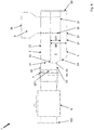
- Fig. 1 shows a schematic sketch of a drain device 1 from the side.
- This drain device 1 has a housing 2 designed as a collecting container with a housing base 21 arranged geodetically below, an inlet 3 opening into the housing 2 and an outlet 4 arranged laterally on the housing 2. With the exception of the inlet 3 and the outlet 4, the housing 2 is designed to be fluid-tight.
- the outlet 4 has a passage opening 41 which forms an overflow vertex 42 which is located geodetically below.
- the latter is arranged higher than the housing base 21, so that a storage height SH in the housing 2 for a fluid F is defined between the housing base 21 and the overflow apex 42.
- an inlet opening 31 is provided which opens into the housing 2 and is arranged geodetically lower than the overflow apex 42.
- an odor trap height GH based on fluid F is defined in the housing 2 between the inlet opening 31 and the overflow apex 42.
- the drain 4 has a horizontally running drain pipe section 43 with a pipe cross-sectional area QF1, which is arranged higher as a whole than the housing base 21.
- the housing 2 has a geodetically arranged housing cover 22, the pipe cross-sectional area QF1 of the horizontally running drain pipe section 43 as a whole is not arranged geodetically higher than this housing cover 22.
- the overflow apex 42 is geodetically arranged above a geodetically lower end of the pipe cross-sectional area QF1, with which the accumulation height SH of the fluid F is higher than this lower end of the pipe cross-sectional area QF1.
- the pipe cross-sectional area QF1 has a geodetically vertical extension and the overflow vertex 42 is arranged in the geodetically arranged 2/3 area of the vertical extension.
- the passage opening 41 geodetically extends from the overflow apex 42 at least substantially to the upper end of the vertical extension of the pipe cross-sectional area QF1.
- Such a passage opening 41 of the drain 4 can be formed in the optional panel 44, which is flat on the side pointing in the direction of the housing 2.
- the diaphragm 44 is preferably seated in the horizontally running drain pipe section 43 and, for this purpose, coming from the direction of the housing 2, can be designed to be insertable into the horizontally running drain pipe section 43.
- the aperture 44 is preferably formed by a cover 45, the passage opening 41 being formed in the cover 45.
- the horizontal drain pipe section 43 should be a socket from the group DN 40, DN 50, DN 70, DN 80, DN 110 and DN 125.
- the drain device 1 has a transition pipe section 5 which forms a reduction from a first pipe section 51 with a larger pipe cross section to a second pipe section 52 with a smaller pipe cross section.
- the housing 2 is formed by the first tube section 51 and a closure element 53, the closure element 53 closing the free end of the first tube section 51.
- the horizontally running drain pipe section 43 is formed by the second pipe section 52.
- a reduction section 54 is arranged between the first and second pipe sections 51, 52.
- the first pipe section 51 has a larger diameter than the second pipe section 52 and comes from the group DN 70, DN 80, DN 100, DN 110, DN 125 and DN 160.
- the inlet 3 has an immersion tube 32 which projects above the housing base 21 geodetically from above through the housing 2 into its interior. Within the housing 2, the immersion tube 32 projects geodetically to below the overflow vertex 42 and forms the inlet opening 31 at the end.
- the inlet 3 has an inlet connection piece 33 which is flow-connected to the immersion tube 32. A hose, pipe or other fluid line can be connected to this.
- the inlet connection piece 33 should have a diameter between 1.905 cm and 2.54 cm (3/4 "and 1").
- outlet pipe section 43 opens into an optional backflow flap 6, so that an outflow of fluid F from the housing 2 and through the outlet pipe section 43 is released and an inflow of fluid F from the direction of the outlet pipe section 43 into the housing 2 is blocked.
- a drainage pipe 103 is connected to the backflow flap 6.
- FIG. 2 is a schematic sketch of the drain device 1 according to Fig. 1 seen from above with the inlet connection piece 33.
- Fig. 3 a schematic sketch of the drain device 1 with the inlet connection piece 33 according to Fig. 1 shown in cross section. Accordingly, regarding the Fig. 2 and 3rd to the explanations Fig. 1 referred.
- Deviating from the execution after Fig. 1 is in Fig. 4 to see a schematic sketch of a drain device 1 with an inlet funnel 34 from the side.
- the drain device 1 detects Fig. 4 instead of the inlet connection piece 33 according to Fig. 1 an inlet funnel 34, which is fluidly connected to the immersion tube 32.
- Out Fig. 5 go one Schematic sketch of the drain device 1 with the inlet funnel 34 according to Fig. 4 in cross section.
- the Fig. 4 and 5 therefore to the comments on the 1 to 3 referred.
- the drain device 1 with all its components is made of the same material, and any sealing rings can also be made of different materials.
- Fig. 6 10 is a schematic diagram of a heat pump device 100 with a drain device 1 according to FIG Fig. 1 refer to.
- the heat pump device 100 has a compressor 104, a throttle 105, a condenser 106 and an evaporator 107.
- a condensate collector with a condensate drain 101 is assigned to these.
- the tubular condensate drain 101 opens into the inlet 3 of the drain device 1.
- the condensate drain opens into the inlet 3 of the drain device 1.
- a heat pump and a ventilation device can be combined with one another in order to temper an air flow with the heat pump.
Landscapes
- Engineering & Computer Science (AREA)
- Chemical & Material Sciences (AREA)
- Combustion & Propulsion (AREA)
- Mechanical Engineering (AREA)
- General Engineering & Computer Science (AREA)
- Physics & Mathematics (AREA)
- Thermal Sciences (AREA)
- Sink And Installation For Waste Water (AREA)
- Devices For Blowing Cold Air, Devices For Blowing Warm Air, And Means For Preventing Water Condensation In Air Conditioning Units (AREA)
- Rigid Pipes And Flexible Pipes (AREA)
Description
- Die Erfindung betrifft eine Ablaufeinrichtung gemäß dem Oberbegriff von Anspruch 1 und eine Wärmepumpen- und/oder Lüftungsvorrichtung, deren Kondensatablauf mit einer solchen Ablaufeinrichtung verbunden ist nach Anspruch 13.
- Ablaufeinrichtungen werden im Stand der Technik dazu eingesetzt, beispielsweise Kondensat von einer Wärmepumpen- und/oder Lüftungsvorrichtung in ein Entwässerungskanalsystem zu überführen. Diese Wärmepumpen- und/oder Lüftungsvorrichtungen dienen der Temperierung und/oder kontrollierten Gebäudelüftung (beispielsweise auch als kontrollierte Wohnraumlüftung (KWL) bezeichnet) und werden oftmals direkt auf der Bodenplatte installiert, sodass sie einen sehr niedrigen Kondensatablauf haben. Der Kondensatablauf dient dazu, gesammeltes Kondensat abzuleiten, das insbesondere auf der Unterdruckseite der Wärmepumpenvorrichtung an kalten Bauteilen oder an Wärmetauschern der Lüftungsvorrichtung anfällt. Meist liegt der Kondensatablauf nur knapp über der Bodenplatte.
- Dabei ist problematisch, dass oftmals kein Bodenablauf in der Bodenplatte vorgesehen ist, sondern eine Entwässerungsrohrleitung oberhalb von der Bodenplatte durch eine Gebäudewand führt. Damit liegt oftmals fast überhaupt kein Leitungsgefälle vor. Trotzdem muss in geeigneter Weise ein Geruchsverschluss in der Art eines Siphons bereitgestellt werden, um zu verhindern, dass Gerüche aus der Entwässerungsrohrleitung in das Gebäude gelangen. In der Praxis führen Handwerkerkonstruktionen zur Herstellung des Geruchsverschlusses aus Standardrohrbauteilen oftmals zu einem Austritt von Kondensat, weil bei der Montage beispielsweise der Rückstau in das Gehäuse der Wärmepumpen- und/oder Lüftungsvorrichtung unberücksichtigt bleibt. In der Folge tritt in der Betriebszeit der Wärmepumpen- und/oder Lüftungsvorrichtung Kondensat aus und es kommt zu Feuchteschäden am Gebäude, die oftmals erst spät bemerkt werden. Der starke Trend hin zur Wärmepumpentechnik als Gebäudeheizungsanlage verschärft diese Problematik.
- Aus
JP 2017 201079 A -
DE 10 2006 053 751 A1 lehrt einen Bodenablauf mit einem komplex ausgestalteten Gehäuse, in dem ein Überlauf ausgebildet ist, hinter dem sich ein seitlicher Ablauf befindet. -
EP 0 807 721 A2 offenbart eine Ablaufarmatur für Dusch- und Badewannen für Keller, Balkone, Terrassen. Dieses weist ein topfförmiges Gehäuse auf, aus dem seitlich ein Ablaufrohr ausmündet. - Aus
CN 202074666 U ist eine Ablaufeinrichtung mit einem kugelförmigen Gehäuse bekannt, in das ein Tauchrohr einmündet, und das einen seitlich angeordneten Ablauf aufweist. - Aufgabe der Erfindung ist es deshalb, eine Ablaufeinrichtung und eine Wärmepumpen- und/oder Lüftungsvorrichtung zu entwickeln, welche einfach und kostengünstig hinsichtlich der Kondensatableitung zu montieren sind und im Betrieb ein dauerhaft sicheres Ableiten von Kondensat auch bei geringen Leitungsgefällen erlaubt, um Wasserschäden zu vermeiden. Die Ablaufeinrichtung ist dabei vorzugsweise kompatibel und nachrüstbar bei einer Vielzahl von Wärmepumpen- und/oder Lüftungsanlagenmodellen, soll einen Geruchsverschluss ausbilden, und soll einfach gegen Rückstau sicherbar sein, sodass auch Wasserschäden durch Rückstau vermieden werden.
- Hauptmerkmale der Erfindung sind in Anspruch 1 und Anspruch 13 angegeben. Ausgestaltungen sind Gegenstand der Ansprüche 2 bis 12 und 14 bis 15.
- Die Erfindung betrifft eine Ablaufeinrichtung mit einem als Sammelbehälter ausgebildeten Gehäuse mit einem geodätisch unten angeordneten Gehäuseboden, einem in das Gehäuse einmündenden Zulauf und einem geodätisch seitlich am Gehäuse angeordneten Ablauf, wobei der Ablauf eine Durchtrittsöffnung aufweist, die einen geodätisch untenliegenden Überlaufscheitel ausbildet, der höher angeordnet ist als der Gehäuseboden. Durch letzteres kann insbesondere eine Stauhöhe im Gehäuse für ein Fluid zwischen dem Gehäuseboden und dem Überlaufscheitel definiert werden. Weiterhin weist der Zulauf eine Zulauföffnung auf, die in das Gehäuse mündet und geodätisch tiefer angeordnet ist als der Überlaufscheitel. Dadurch wird im Gehäuse insbesondere eine auf Fluid basierende Geruchsverschlusshöhe zwischen der Zulauföffnung und dem Überlaufscheitel definiert. Der Ablauf weist einen horizontal verlaufenden Ablaufrohrabschnitt mit einer Rohrquerschnittsfläche auf, die (insbesondere als Ganzes) höher angeordnet ist als der Gehäuseboden, wobei der Überlaufscheitel geodätisch oberhalb von einem geodätisch untenliegenden Ende der Rohrquerschnittsfläche angeordnet ist. Damit lässt sich insbesondere erreichen, dass die Stauhöhe höher liegt als dieses untenliegende Ende der Rohrquerschnittsfläche.
- Vorteilhaft an dieser Ausgestaltung ist, dass obwohl der Ablaufrohrabschnitt recht tief am Gehäuse platziert sein kann, die Stauhöhe mittels dem Überlaufscheitel nach oben verlagert ist. Damit ist der Aufbau der Ablaufeinrichtung flach ausführbar und es wird dennoch eine große Fluidsäule für den Geruchsverschluss erzielt. Gegenüber einem als Rohrbogen ausgeführten Siphon ist außerdem ein vergleichsweise großes flaches Gehäuse bereitstellbar, sodass in der betriebslosen Zeit der Wärmepumpen- und/oder Lüftungsvorrichtung relativ lange ein sicherer Geruchsverschluss erzielt wird. Es steht nämlich ein vergleichsweise großes Fluidvolumen bereit, das zunächst verdunsten müsste. Dabei sollte das Gehäuse mit Ausnahme des Zulaufs und des Ablaufs fluiddicht ausgebildet sein. Hierdurch wird Verdunstung vermieden und selbst bei einem Rückstau tritt zumindest im Bereich der Ablaufeinrichtung kein Fluid aus. Alle Richtungsangaben mit Bezug auf die Geodäsie beziehen sich auf eine Ausrichtung in der für den Betrieb vorgesehenen Montagelage.
- Die Rohrquerschnittsfläche des horizontal verlaufenden Ablaufrohrabschnitts weist eine geodätisch vertikale Erstreckung auf, wobei der Überlaufscheitel vorzugsweise im geodätisch oben angeordneten 2/3-Bereich der vertikalen Erstreckung angeordnet ist. Damit liegt der Überlaufscheitel hoch und trotzdem kann die Durchtrittsöffnung noch eine recht große Querschnittsfläche haben. Dabei ist zu bevorzugen, dass sich die Durchtrittsöffnung geodätisch zumindest im Wesentlichen bis an das obere Ende der vertikalen Erstreckung der Rohrquerschnittsfläche erstreckt. Damit wird die verfügbare Höhe voll ausgenutzt, die Ablaufeinrichtung ist flach ausgestaltbar und kann auf einfache Weise gegen Rückstau gesichert werden.
- In einer Ausgestaltungsvariante besteht das Gehäuse aus Kunststoff, vorzugsweise aus einem Kunststoff aus der Gruppe Polyethylen (PE) oder Polypropylen (PP), Polyvinylchlorid (PVC), Styrol-Copolymerisate (ABS/ASA) und Polyesterharz (UP). Damit kann ein geeignetes Material passend zu einer sich anschließenden Entwässerungsleitung ausgewählt werden.
- Weiterhin kann vorgesehen sein, dass der Zulauf aus Kunststoff besteht, vorzugsweise aus einem Kunststoff aus der Gruppe Polyethylen (PE) oder Polypropylen (PP), Polyvinylchlorid (PVC), Styrol-Copolymerisate (ABS/ASA) und Polyesterharz (UP).
- Schließlich kann der horizontal verlaufende Ablaufrohrabschnitt aus Kunststoff bestehen, vorzugsweise aus einem Kunststoff aus der Gruppe Polyethylen (PE) oder Polypropylen (PP), Polyvinylchlorid (PVC), Styrol-Copolymerisate (ABS/ASA) und Polyesterharz (UP). Dies Kunststoffe haben sich jeweils für Leitungen in der Gebäudetechnik bewährt.
- Gemäß einer speziellen Ausgestaltung der Erfindung ist die Durchtrittsöffnung des Ablaufs in einer Blende ausgebildet. Eine solche ist wenig komplex, einfach herstellbar und platzsparend. Dabei bietet sich als Material an, dass die Blende aus Kunststoff besteht, vorzugsweise aus einem Kunststoff aus der Gruppe Polyethylen (PE) oder Polypropylen (PP), Polyvinylchlorid (PVC), Styrol-Copolymerisate (ABS/ASA) und Polyesterharz (UP). Besonders platzsparend kann eine Variante ausgeführt sein, bei der die Blende auf der in Richtung Gehäuse weisenden Seite flach ausgebildet ist.
- In einer Anordnungsoption sitzt die Blende in dem horizontal verlaufenden Ablaufrohrabschnitt. Entsprechend klein und platzsparend ist die Blende anordenbar.
- Dabei ist eine Ausführung realisierbar, gemäß der die Blende aus Richtung des Gehäuses kommend in den horizontal verlaufenden Ablaufrohrabschnitt eingesetzt ist. Nachdem sie von innen eingesetzt ist, z.B. durch Herstellermontage, wird ein Handwerker deren Position nicht mehr verändern und es wird eine Montagefehlerquelle vermieden.
- Gemäß einer besonderen Ausführungsform ist die Blende durch einen Deckel ausgebildet, wobei die Durchtrittsöffnung in dem Deckel ausgebildet ist. Ein Deckel lässt sich auf einfache Weise in seinem Sitz montieren, der hierzu am Gehäuse und/oder horizontal verlaufenden Ablaufrohrabschnitt auszubilden ist.
- Eine hohe Kompatibilität der Ablaufeinrichtung ohne Sonderlösungen des Monteurs wird erreicht, wenn der horizontal verlaufende Ablaufrohrabschnitt aus der Gruppe DN 40, DN 50, DN 70, DN 80, DN 110 und DN 125 ist. Eine Ausbildung des Ablaufrohrabschnitts als Stutzen ist ebenfalls von Vorteil, denn meistens wird eine Muffe als Anschluss der Entwässerungsrohrleitung zur Verfügung stehen.
- Die erfindungsgemäße Ablaufeinrichtung ist besonders kostengünstig herstellbar, weil diese ein (vorzugsweise genormtes) Übergangsrohrstück aufweist, das eine Reduktion von einem ersten Rohrabschnitt mit einem größeren Rohrquerschnitt auf einen zweiten Rohrabschnitt mit einem kleineren Rohrquerschnitt ausbildet, wobei das Gehäuse von dem ersten Rohrabschnitt und einem Verschlusselement, das das freie Ende des ersten Rohrabschnitts verschließt, ausgebildet ist, und wobei der horizontal verlaufende Ablaufrohrabschnitt von dem zweiten Rohrabschnitt ausgebildet ist. Derartige Übergangsrohrstücke existieren nämlich in recht großer Variantenvielzahl als Fertigteile und es sind entsprechend keine Spezialwerkzeuge für die Herstellung des Gehäuses und des horizontal verlaufenden Ablaufrohrabschnitts notwendig. Selbst die Verschlusselemente existieren als Fertigware.
- Vorzugsweise sind der erste und der zweite Rohrabschnitt des Übergangsrohrabschnitts gleich ausgerichtet, insbesondere achsparallel ausgerichtet, und in der Einbaulage insbesondere horizontal ausgerichtet. Weiter bevorzugt ist der zweite Rohrabschnitt versetzt zum ersten Rohrabschnitt angeordnet. Hierbei ist ein Versatz zu bevorzugen, bei dem der zweite Rohrabschnitt geodätisch höher angeordnet ist als der erste Rohrabschnitt. Vorzugsweise liegt der Rohrquerschnitt des zweiten Rohrabschnitts aber noch ganz oder zumindest zur Hälfte in der horizontalen Projektion des Rohrquerschnitts des ersten Rohrabschnittes. Dabei gibt es kurze Übergangsrohrstücke mit sprunghafter Querschnittsveränderung, die eingesetzt werden können. Bevorzugt wird jedoch ein Übergangsrohrstück eingesetzt, bei dem zwischen dem ersten und zweiten Rohrabschnitt ein Reduktionsabschnitt angeordnet ist, insbesondere ein trichterförmiger Reduktionsabschnitt. Dieser bildet einen langsameren Querschnittsübergang aus. Als Material bietet es sich an, dass das Übergangsrohrstück aus Kunststoff besteht, vorzugsweise aus einem Kunststoff aus der Gruppe Polyethylen (PE) oder Polypropylen (PP), Polyvinylchlorid (PVC), Styrol-Copolymerisate (ABS/ASA) und Polyesterharz (UP). Für das Verschlusselement bieten sich die gleichen Materialien an.
- Nach einer optionalen Ausgestaltung ist der erste Rohrabschnitt aus der Gruppe DN 70, DN 80, DN 100, DN 110, DN 125 und DN 160. Entsprechend kann ein Fertigteil als Übergangsrohrstück für die Ablaufeinrichtung verwendet werden.
- Weiterhin ist gemäß einer Ausführungsvariante vorgesehen, dass der Zulauf ein Tauchrohr aufweist, das innerhalb von dem Gehäuse geodätisch bis unter den Überlaufscheitel ragt und endseitig die Zulauföffnung ausbildet. Rohre stehen in großer Vielzahl als Fertigbauteile zur Verfügung und halten die Gesamtkosten der Ablaufeinrichtung gering. Bevorzugt besteht das Tauchrohr aus Kunststoff, insbesondere aus einem Kunststoff aus der Gruppe Polyethylen (PE) oder Polypropylen (PP), Polyvinylchlorid (PVC), Styrol-Copolymerisate (ABS/ASA) und Polyesterharz (UP). Dieser ist leicht, preiswert und beständig. Optional kann das Tauchrohr oberhalb von dem Gehäuseboden durch das Gehäuse in dessen Innenraum hineinragen, vorzugsweise geodätisch von oben. Damit ist die potentiell zu Undichtigkeit neigende Durchführung des Tauchrohres durch das Gehäuse oberhalb von dem Überlaufscheitel angeordnet und es kann hier keine Flüssigkeit austreten.
- Vorzugsweise beträgt die Sperrwasserhöhe der Ablaufeinrichtung wenigstens 50 mm. Hierzu sollte der Zulauf wenigstens 50 mm unterhalb des Überlaufscheitels angeordnet sein. Hierdurch wird auch bei längeren Betriebspausen, beispielsweise im Sommer, hinreichend lange ein ausreichender Geruchsverschluss bereitgestellt.
- Außerdem ist es zu bevorzugen, wenn das Sperrwasservolumen, also das Flüssigkeitsvolumen zwischen dem Zulauf und dem Überlaufscheitel wenigstens 0,52 I beträgt. Durch das vergleichsweise große Flüssigkeitsvolumen wird auch bei längeren Betriebspausen, hinreichend lange ein ausreichender Geruchsverschluss bereitgestellt, denn die Verdunstungsdauer bis zur Unterschreitung der Höhe des Zulaufs ist lang. So liegt das Sperrwasservolumen insbesondere bei Dusch-, Badewannen- und Waschbeckenabläufen meist unter 0,25 I.
- Des Weiteren sollte die Ablaufeinrichtung im Bereich des kleinsten Querschnitts einen Mindestdurchfluss von 0,8 I/s haben. Hierdurch sind auch große Kondenswassermengen schnell ableitbar, ohne dass es zu einem Rückstau kommt. Dies ist deutlich mehr als beispielsweise bei Duschwannenabläufen für bodenebene Duschen, die lediglich bis zu 0,4 I/s Mindestdurchfluss erreichen. Erzielbar ist der Mindestdurchfluss von 0,8 I/s insbesondere, indem der Strömungsquerschnitt im Bereich des minimalen Durchmessers 30 mm beträgt, bzw. ein nicht-kreisrunder minimaler Strömungsquerschnitt wenigstens 7 cm2 beträgt.
- Je nach der anzuschließenden Fluidquelle kann der Zulauf einen Zulaufanschlussstutzen oder einen Zulauftrichter aufweisen, der mit dem Tauchrohr strömungsverbunden ist. In einen Zulauftrichter kann beispielsweise ein Hahn ausmünden. Ein Zulaufanschlussstutzen ist insbesondere zum Anschluss eines Rohres oder Schlauches geeignet. Dabei sollte der Zulaufanschlussstutzen einen Durchmesser zwischen 1.905cm und 2.54cm ( 3/4" und 1") haben. Es bietet sich auch hier an, dass der Zulauftrichter oder der Zulaufanschlussstutzen aus Kunststoff besteht, vorzugsweise aus einem Kunststoff aus der Gruppe Polyethylen (PE) oder Polypropylen (PP), Polyvinylchlorid (PVC), Styrol-Copolymerisate (ABS/ASA) und Polyesterharz (UP).
- Zur Absicherung gegen rückwärts einströmendes Wasser, z.B. bei starken Regenfällen, kann die Ablaufeinrichtung optional dadurch ergänzt sein, dass diese auf Seiten des Ablaufrohrabschnitts eine Rückstauklappe aufweist. Diese sollte insbesondere ein Ausströmen von Fluid aus dem Gehäuse und durch den Ablaufrohrabschnitt freigeben und ein Einströmen von Fluid aus Richtung von dem Ablaufrohrabschnitt in das Gehäuse sperren.
- Ein besonders flacher Aufbau wird erzielt, wenn das Gehäuse eine geodätisch oben angeordnete Gehäusedecke aufweist, wobei die Rohrquerschnittsfläche des horizontal verlaufenden Ablaufrohrabschnitts geodätisch nicht höher angeordnet ist als die Gehäusedecke.
- Die Erfindung betrifft außerdem eine Wärmepumpen- und/oder Lüftungsvorrichtung, insbesondere für Gebäude, mit einem Kondensatablauf, der in den Zulauf einer Ablaufeinrichtung, wie sie vor- und nachstehen beschrieben ist, einmündet. Bei einer solchen Kombination kann selbst dicht über dem Aufstellungsboden anfallendes Kondenswasser sicher über die Ablaufeinrichtung abgeführt werden und ein Geruchsdurchtritt sowie Wasserschäden werden wirksam vermieden. Die Variante der Wärmepumpenvorrichtung verfügt vorzugsweise über einen Verdichter, eine Drossel, einen Kondensator und einen Verdampfer. Das Kondensat fällt typischerweise auf der Seite des Verdampfers an. Bei Wärmepumpenvorrichtungen mit Umkehrbetrieb können der Verdampfer und der Kondensator ihre Funktion tauschen. Die alternative Variante der Lüftungsvorrichtung weist vorzugsweise einen Wärmetauscher auf, beispielsweise einen Gegenstromwärmetauscher oder Kreuzgegenstromwärmetauscher. Hier fällt das Kondensat typischerweise in dem Strömungskanal an, in dem sich der Luftstrom in Strömungsrichtung abkühlt. Je nach Betrieb kann dies beispielsweise in ein Gebäude hineinströmende oder aus diesem herausströmende Luft sein. In der Kombination der Wärmepumpen- und Lüftungsvorrichtung wird ein Luftstrom mittels der Wärmepumpe temperiert.
- Vorzugsweise ist der Ablaufrohrabschnitt an eine Entwässerungsrohrleitung angeschlossen. Damit lässt sich das Fluid wegleiten. Die Vorteile des flachen Aufbaus der Ablaufeinrichtung kommen vor allem zur Geltung, wenn die Entwässerungsrohrleitung auf der geodätischen Höhe des horizontal verlaufenden Ablaufrohrabschnitts durch eine Gebäudewand führt.
- Weitere Merkmale, Einzelheiten und Vorteile der Erfindung ergeben sich aus dem Wortlaut der Ansprüche sowie aus der folgenden Beschreibung von Ausführungsbeispielen anhand der Zeichnungen. Es zeigen:
- Fig. 1
- eine Schemaskizze einer Ablaufeinrichtung mit einem Zulaufanschlussstutzen von der Seite;
- Fig. 2
- eine Schemaskizze einer Ablaufeinrichtung mit einem Zulaufanschlussstutzen von oben;
- Fig. 3
- eine Schemaskizze einer Ablaufeinrichtung mit einem Zulaufanschlussstutzen im Querschnitt;
- Fig. 4
- eine Schemaskizze einer Ablaufeinrichtung mit einem Zulauftrichter von der Seite;
- Fig. 5
- eine Schemaskizze einer Ablaufeinrichtung mit einem Zulauftrichter im Querschnitt; und
- Fig. 6
- eine Schemaskizze einer Wärmepumpenvorrichtung mit einer Ablaufeinrichtung nach
Fig. 1 . -
Fig. 1 zeigt eine Schemaskizze einer Ablaufeinrichtung 1 von der Seite. Diese Ablaufeinrichtung 1 weist ein als Sammelbehälter ausgebildetes Gehäuse 2 mit einem geodätisch unten angeordneten Gehäuseboden 21, einen in das Gehäuse 2 einmündenden Zulauf 3 und einen geodätisch seitlich am Gehäuse 2 angeordneten Ablauf 4 auf. Das Gehäuse 2 ist mit Ausnahme des Zulaufs 3 und des Ablaufs 4 fluiddicht ausgebildet. - Der Ablauf 4 hat eine Durchtrittsöffnung 41, die einen geodätisch untenliegenden Überlaufscheitel 42 ausbildet. Letzterer ist höher angeordnet als der Gehäuseboden 21, sodass eine Stauhöhe SH im Gehäuse 2 für ein Fluid F zwischen dem Gehäuseboden 21 und dem Überlaufscheitel 42 definiert ist.
- Auf Seiten des Zulaufs 3 ist eine Zulauföffnung 31 vorgesehen, die in das Gehäuse 2 mündet und geodätisch tiefer angeordnet ist als der Überlaufscheitel 42. Hierdurch ist im Gehäuse 2 eine auf Fluid F basierende Geruchsverschlusshöhe GH zwischen der Zulauföffnung 31 und dem Überlaufscheitel 42 definiert.
- Weiterhin verfügt der Ablauf 4 über einen horizontal verlaufenden Ablaufrohrabschnitt 43 mit einer Rohrquerschnittsfläche QF1, die als Ganzes höher angeordnet ist als der Gehäuseboden 21. Dabei hat das Gehäuse 2 eine geodätisch oben angeordnete Gehäusedecke 22, wobei die Rohrquerschnittsfläche QF1 des horizontal verlaufenden Ablaufrohrabschnitts 43 als Ganzes geodätisch nicht höher angeordnet ist als diese Gehäusedecke 22. Der Überlaufscheitel 42 ist geodätisch oberhalb von einem geodätisch untenliegenden Ende der Rohrquerschnittsfläche QF1 angeordnet, womit die Stauhöhe SH des Fluids F höher liegt als dieses untenliegende Ende der Rohrquerschnittsfläche QF1. Insbesondere weist die Rohrquerschnittsfläche QF1 eine geodätisch vertikale Erstreckung auf und der Überlaufscheitel 42 ist im geodätisch oben angeordneten 2/3-Bereich der vertikalen Erstreckung angeordnet. Die Durchtrittsöffnung 41 erstreckt sich von dem Überlaufscheitel 42 geodätisch zumindest im Wesentlichen bis an das obere Ende der vertikalen Erstreckung der Rohrquerschnittsfläche QF1 heran.
- Eine solche Durchtrittsöffnung 41 des Ablaufs 4 kann in der optionalen Blende 44 ausgebildet sein, die auf der in Richtung Gehäuse 2 weisenden Seite flach ausgebildet ist. Die Blende 44 sitzt bevorzugt in dem horizontal verlaufenden Ablaufrohrabschnitt 43 und kann hierzu aus Richtung des Gehäuses 2 kommend in den horizontal verlaufenden Ablaufrohrabschnitt 43 einsetzbar ausgestaltet sein. Bevorzugt ist die Blende 44 durch einen Deckel 45 ausgebildet, wobei die Durchtrittsöffnung 41 in dem Deckel 45 ausgebildet ist.
- Für eine hohe Kompatibilität mit Gebäudeentwässerungsleitungen sollte der horizontal verlaufende Ablaufrohrabschnitt 43 ein Stutzen aus der Gruppe DN 40, DN 50, DN 70, DN 80, DN 110 und DN 125 sein.
- Vorliegend weist die Ablaufeinrichtung 1 ein Übergangsrohrstück 5 auf, das eine Reduktion von einem ersten Rohrabschnitt 51 mit einem größeren Rohrquerschnitt auf einen zweiten Rohrabschnitt 52 mit einem kleineren Rohrquerschnitt ausbildet. Das Gehäuse 2 ist von dem ersten Rohrabschnitt 51 und einem Verschlusselement 53 ausgebildet, wobei das Verschlusselement 53 das freie Ende des ersten Rohrabschnitts 51 verschließt. Der horizontal verlaufende Ablaufrohrabschnitt 43 ist von dem zweiten Rohrabschnitt 52 ausgebildet. Zwischen dem ersten und zweiten Rohrabschnitt 51, 52 ist ein Reduktionsabschnitt 54 angeordnet. Der erste Rohrabschnitt 51 hat einen größeren Durchmesser als der zweite Rohrabschnitt 52 und stammt aus der Gruppe DN 70, DN 80, DN 100, DN 110, DN 125 und DN 160.
- Der Zulauf 3 weist ein Tauchrohr 32 auf, das oberhalb von dem Gehäuseboden 21 geodätisch von oben durch das Gehäuse 2 in dessen Innenraum hineinragt. Innerhalb von dem Gehäuse 2 ragt das Tauchrohr 32 geodätisch bis unter den Überlaufscheitel 42 und bildet endseitig die Zulauföffnung 31 aus. Außerdem weist der Zulauf 3 einen Zulaufanschlussstutzen 33 auf, der mit dem Tauchrohr 32 strömungsverbunden ist. Hieran lässt sich ein Schlauch, ein Rohr oder eine sonstige Fluidleitung anschließen. Hierzu sollte der Zulaufanschlussstutzen 33 einen Durchmesser zwischen 1.905cm und 2.54cm (3/4" und 1") haben.
- Des Weiteren mündet der Ablaufrohrabschnitt 43 in eine optionale Rückstauklappe 6, sodass ein Ausströmen von Fluid F aus dem Gehäuse 2 und durch den Ablaufrohrabschnitt 43 freigegeben und ein Einströmen von Fluid F aus Richtung von dem Ablaufrohrabschnitt 43 in das Gehäuse 2 gesperrt ist. An die Rückstauklappe 6 ist eine Entwässerungsrohrleitung 103 angeschlossen.
- In
Fig. 2 ist eine Schemaskizze der Ablaufeinrichtung 1 gemäßFig. 1 mit dem Zulaufanschlussstutzen 33 von oben zu sehen. Zusätzlich ist inFig. 3 eine Schemaskizze der Ablaufeinrichtung 1 mit dem Zulaufanschlussstutzen 33 gemäßFig. 1 im Querschnitt dargestellt. Entsprechend wird bezüglich denFig. 2 und3 auf die Ausführungen zuFig. 1 verwiesen. - Abweichend zu der Ausführung nach
Fig. 1 ist inFig. 4 eine Schemaskizze einer Ablaufeinrichtung 1 mit einem Zulauftrichter 34 von der Seite zu sehen. Insbesondere weist die Ablaufeinrichtung 1 nachFig. 4 anstatt des Zulaufanschlussstutzen 33 gemäßFig. 1 einen Zulauftrichter 34 auf, der mit dem Tauchrohr 32 strömungsverbunden ist. AusFig. 5 geht eine Schemaskizze der Ablaufeinrichtung 1 mit dem Zulauftrichter 34 gemäßFig. 4 im Querschnitt hervor. Im Weiteren wird bezüglich denFig. 4 und5 daher auf die Ausführungen zu denFig. 1 bis 3 verwiesen. - Unabhängig von den
Figuren 1 ,2 ,3 ,4 ,5 und6 eignet sich als Material für das Gehäuse 2, den Zulauf 3, den horizontal verlaufenden Ablaufrohrabschnitt 43, die Blende 44, das Übergangsrohrstück 5, das Verschlusselement 53, das Tauchrohr 32, den Zulaufanschlussstutzen 33 und den Zulauftrichter 34 jeweils ein Kunststoff, insbesondere ein Kunststoff aus der Gruppe Polyethylen (PE) oder Polypropylen (PP), Polyvinylchlorid (PVC), Styrol-Copolymerisate (ABS/ASA) und Polyesterharz (UP). Bevorzugt ist die Ablaufeinrichtung 1 mit all ihren Bestandteilen aus dem gleichen Material hergestellt, wobei etwaige Dichtringe auch aus abweichenden Materialien bestehen können. -
Fig. 6 ist eine Schemaskizze einer Wärmepumpenvorrichtung 100 mit einer Ablaufeinrichtung 1 gemäßFig. 1 zu entnehmen. Hinsichtlich der Bestandteile der Ablaufeinrichtung 1 wird daher zunächst auf die Beschreibung derFig. 1 verwiesen. Zusätzlich erkennt man inFig. 6 , dass die Wärmepumpenvorrichtung 100 einen Verdichter 104, eine Drossel 105, einen Kondensator 106 und einen Verdampfer 107 aufweist. Diesen ist ein Kondensatsammler mit einem Kondensatablauf 101 zugeordnet. Der rohrförmige Kondensatablauf 101 mündet in den Zulauf 3 der Ablaufeinrichtung 1 ein. Die an den Ablaufrohrabschnitt 43 mittelbar über die Rückstauklappe 6 angeschlossene Entwässerungsrohrleitung 103 führt auf der geodätischen Höhe des horizontal verlaufenden Ablaufrohrabschnitts 43 durch eine Gebäudewand 110. Alternativ zu der Wärmepumpenvorrichtung 100 kann auch eine Lüftungsvorrichtung, die beispielsweise einen (Kreuz-) Gegenstromwärmetauscher aufweist, mit ihrem Kondensatablauf in den Zulauf 3 der Ablaufeinrichtung 1 einmünden. Außerdem können eine Wärmepumpen- und eine Lüftungsvorrichtung miteinander kombiniert sein, um einen Luftstrom mit der Wärmepumpe zu temperieren.Bezugszeichenliste 1 Ablaufeinrichtung 53 Verschlusselement 54 Reduktionsabschnitt 2 Gehäuse 21 Gehäuseboden 6 Rückstauklappe 22 Gehäusedecke 100 Wärmepumpen- und/oder 3 Zulauf Lüftungsvorrichtung 31 Zulauföffnung 101 Kondensatablauf 32 Tauchrohr 103 Entwässerungsrohrleitung 33 Zulaufanschlussstutzen 104 Verdichter 34 Zulauftrichter 105 Drossel 106 Kondensator 4 Ablauf 107 Verdampfer 41 Durchtrittsöffnung 42 Überlaufscheitel 110 Gebäudewand 43 Ablaufrohrabschnitt 44 Blende F Fluid 45 Deckel GH Geruchsverschlusshöhe QF1 Rohrquerschnittsfläche 5 Übergangsrohrstück SH Stauhöhe 51 erster Rohrabschnitt 52 zweiter Rohrabschnitt
Claims (15)
- Ablaufeinrichtung (1)- mit einem als Sammelbehälter ausgebildeten Gehäuse (2) mit einem geodätisch unten angeordneten Gehäuseboden (21), und- mit einem in das Gehäuse einmündenden Zulauf (3) und einem geodätisch seitlich am Gehäuse (2) angeordneten Ablauf (4),- wobei der Ablauf (4) eine Durchtrittsöffnung (41) aufweist,
o die einen geodätisch untenliegenden Überlaufscheitel (42) ausbildet, der höher angeordnet ist als der Gehäuseboden (21),- wobei der Zulauf (3) eine Zulauföffnung (31) aufweist, die in das Gehäuse (2) mündet und geodätisch tiefer angeordnet ist als der Überlaufscheitel (42),- wobei der Ablauf (4) einen horizontal verlaufenden Ablaufrohrabschnitt (43) mit einer Rohrquerschnittsfläche (QF1) aufweist, die höher angeordnet ist als der Gehäuseboden (21), und- wobei der Überlaufscheitel (42) geodätisch oberhalb von einem geodätisch untenliegenden Ende der Rohrquerschnittsfläche (QF1) angeordnet ist,
dadurch gekennzeichnet, dass- die Ablaufeinrichtung (1) ein Übergangsrohrstück (5) aufweist, das eine Reduktion von einem ersten Rohrabschnitt (51) mit einem größeren Rohrquerschnitt auf einen zweiten Rohrabschnitt (52) mit einem kleineren Rohrquerschnitt ausbildet,- wobei das Gehäuse (2) von dem ersten Rohrabschnitt (51) und einem Verschlusselement (53), das das freie Ende des ersten Rohrabschnitts (51) verschließt, ausgebildet ist, und- wobei der horizontal verlaufende Ablaufrohrabschnitt (43) von dem zweiten Rohrabschnitt (52) ausgebildet ist. - Ablaufeinrichtung (1) nach Anspruch 1, dadurch gekennzeichnet, dass die Durchtrittsöffnung (41) des Ablaufs (4) in einer Blende (44) ausgebildet ist.
- Ablaufeinrichtung (1) nach Anspruch 2, dadurch gekennzeichnet, dass die Blende (44) in dem horizontal verlaufenden Ablaufrohrabschnitt (43) sitzt.
- Ablaufeinrichtung (1) nach einem der Ansprüche 2 oder 3, dadurch gekennzeichnet, dass die Blende (44) aus Richtung des Gehäuses (2) kommend in den horizontal verlaufenden Ablaufrohrabschnitt (43) eingesetzt ist.
- Ablaufeinrichtung (1) nach einem der Ansprüche 2 bis 4, dadurch gekennzeichnet, dass die Blende (44) durch einen Deckel (45) ausgebildet ist, wobei die Durchtrittsöffnung (41) in dem Deckel (45) ausgebildet ist.
- Ablaufeinrichtung (1) nach einem der vorhergehenden Ansprüche, dadurch gekennzeichnet, dass der horizontal verlaufende Ablaufrohrabschnitt (43) aus der Gruppe DN 40, DN 50, DN 70, DN 80, DN 110 und DN 125 ist.
- Ablaufeinrichtung (1) nach einem der vorhergehenden Ansprüche, dadurch gekennzeichnet, dass der erste und der zweite Rohrabschnitt (51, 52) des Übergangsrohrabschnitts (5) gleich ausgerichtet sind und der zweite Rohrabschnitt (52) versetzt zum ersten Rohrabschnitt (51) angeordnet ist, wobei ein Versatz vorliegt, bei dem der zweite Rohrabschnitt (52) geodätisch höher angeordnet ist als der erste Rohrabschnitt (51), wobei der Rohrquerschnitt des zweiten Rohrabschnitts (52) ganz oder zumindest zur Hälfte in der horizontalen Projektion des Rohrquerschnitts des ersten Rohrabschnittes (51) liegt.
- Ablaufeinrichtung (1) nach einem der vorhergehenden Ansprüche, dadurch gekennzeichnet, dass der erste Rohrabschnitt (51) aus der Gruppe DN 70, DN 80, DN 100, DN 110, DN 125 und DN 160 ist.
- Ablaufeinrichtung (1) nach einem der vorhergehenden Ansprüche, dadurch gekennzeichnet, dass der Zulauf (3) ein Tauchrohr (32) aufweist, das innerhalb von dem Gehäuse (2) geodätisch bis unter den Überlaufscheitel (42) ragt und endseitig die Zulauföffnung (31) ausbildet.
- Ablaufeinrichtung (1) nach Anspruch 9, dadurch gekennzeichnet, dass der Zulauf (3) einen Zulaufanschlussstutzen (33) oder einen Zulauftrichter (34) aufweist, der mit dem Tauchrohr (32) strömungsverbunden ist.
- Ablaufeinrichtung (1) nach einem der vorhergehenden Ansprüche, dadurch gekennzeichnet, dass diese auf Seiten des Ablaufrohrabschnitts (43) eine Rückstauklappe (6) aufweist.
- Ablaufeinrichtung (1) nach einem der vorhergehenden Ansprüche, dadurch gekennzeichnet, dass das Gehäuse (2) eine geodätisch oben angeordnete Gehäusedecke (22) aufweist, wobei die Rohrquerschnittsfläche (QF1) des horizontal verlaufenden Ablaufrohrabschnitts (43) geodätisch nicht höher angeordnet ist als die Gehäusedecke (22).
- Wärmepumpen- und/oder Lüftungsvorrichtung (100) mit einer Ablaufeinrichtung (1) gemäß einem der vorhergehenden Ansprüche und mit einem Kondensatablauf (101), der in den Zulauf (3) der Ablaufeinrichtung (1) einmündet.
- Wärmepumpen- und/oder Lüftungsvorrichtung (100) nach Anspruch 13, dadurch gekennzeichnet, dass der Ablaufrohrabschnitt (43) an eine Entwässerungsrohrleitung (103) angeschlossen ist.
- Wärmepumpen- und/oder Lüftungsvorrichtung (100) nach einem der Ansprüche 13 oder 14, dadurch gekennzeichnet, dass die Entwässerungsrohrleitung (103) auf der geodätischen Höhe des horizontal verlaufenden Ablaufrohrabschnitts (43) durch eine Gebäudewand (110) führt.
Priority Applications (1)
| Application Number | Priority Date | Filing Date | Title |
|---|---|---|---|
| PL19162042T PL3540328T3 (pl) | 2018-03-14 | 2019-03-11 | Instalacja odpływowa |
Applications Claiming Priority (1)
| Application Number | Priority Date | Filing Date | Title |
|---|---|---|---|
| DE102018105938.8A DE102018105938A1 (de) | 2018-03-14 | 2018-03-14 | Ablaufeinrichtung und Wärmepumpen- und/oder Lüftungsvorrichtung hiermit |
Publications (2)
| Publication Number | Publication Date |
|---|---|
| EP3540328A1 EP3540328A1 (de) | 2019-09-18 |
| EP3540328B1 true EP3540328B1 (de) | 2020-06-03 |
Family
ID=65766846
Family Applications (1)
| Application Number | Title | Priority Date | Filing Date |
|---|---|---|---|
| EP19162042.6A Active EP3540328B1 (de) | 2018-03-14 | 2019-03-11 | Ablaufeinrichtung |
Country Status (4)
| Country | Link |
|---|---|
| EP (1) | EP3540328B1 (de) |
| DE (1) | DE102018105938A1 (de) |
| ES (1) | ES2807240T3 (de) |
| PL (1) | PL3540328T3 (de) |
Families Citing this family (2)
| Publication number | Priority date | Publication date | Assignee | Title |
|---|---|---|---|---|
| CN115387451A (zh) * | 2022-08-04 | 2022-11-25 | 中国建筑第四工程局有限公司 | 一种住宅新型空调冷凝水阻断式环保地漏 |
| DE102023100254A1 (de) * | 2023-01-06 | 2024-07-11 | Solvis GmbH | Heizungsanlage und Siphon |
Family Cites Families (5)
| Publication number | Priority date | Publication date | Assignee | Title |
|---|---|---|---|---|
| AT400897B (de) * | 1992-04-21 | 1996-04-25 | Vaillant Gmbh | Siphon für kondensat einer heizeinrichtung |
| DE19619942A1 (de) * | 1996-05-17 | 1997-11-20 | Viegener Ii Fa Franz | Ablaufarmatur für Dusch- und Badewannen, für Keller, Balkone, Terrassen o. dgl. |
| DE102006053751A1 (de) * | 2006-11-13 | 2008-05-15 | Hansgrohe Ag | Ablaufarmatur |
| CN202074666U (zh) * | 2011-05-26 | 2011-12-14 | 中国电子系统工程第四建设有限公司 | 一种空调机组负压段同层排水装置 |
| JP6684468B2 (ja) * | 2016-05-02 | 2020-04-22 | Toto株式会社 | 排水トラップ洗浄システム |
-
2018
- 2018-03-14 DE DE102018105938.8A patent/DE102018105938A1/de active Pending
-
2019
- 2019-03-11 PL PL19162042T patent/PL3540328T3/pl unknown
- 2019-03-11 EP EP19162042.6A patent/EP3540328B1/de active Active
- 2019-03-11 ES ES19162042T patent/ES2807240T3/es active Active
Non-Patent Citations (1)
| Title |
|---|
| None * |
Also Published As
| Publication number | Publication date |
|---|---|
| PL3540328T3 (pl) | 2020-09-21 |
| EP3540328A1 (de) | 2019-09-18 |
| ES2807240T3 (es) | 2021-02-22 |
| DE102018105938A1 (de) | 2019-09-19 |
Similar Documents
| Publication | Publication Date | Title |
|---|---|---|
| DE60021136T2 (de) | Drainagesystem für ein Gebäude | |
| EP2453065B1 (de) | Ablaufgarnitur mit verdeckt positionierbarem Überlauf | |
| DE102011051430B4 (de) | Abwasserablauf mit Geruchsverschluss | |
| EP2045403B1 (de) | Ablaufgarnitur mit integriertem Überlauf | |
| EP3722525A1 (de) | Heizbarer spülkasten für intelligente toilette | |
| DE102012003533A1 (de) | Abflussvorrichtung mit einer integrierten Wärmetauscheinrichtung | |
| EP3540328A1 (de) | Ablaufeinrichtung | |
| DE102014012288A1 (de) | Regenwasserfilter | |
| EP3502364B1 (de) | Rohrbelüfter und system zur rohrbelüftung | |
| DE202007011126U1 (de) | Sedimentationsanlage | |
| DE10201347C5 (de) | Einlaufvorrichtung für die Abführung von Regenwasser von einem Dach | |
| DE102018217228A1 (de) | Trinkwasserverteilungsmodul zum Verbinden einer Basisleitung mit einer Hauptzirkulationsleitung | |
| EP4403713B1 (de) | Sanitäre anlage, insbesondere dusche | |
| EP2639369B1 (de) | Rückstausicherung für Abwasseranlagen | |
| EP1035262B1 (de) | Hebeanlage für Abwasser | |
| EP2275747A2 (de) | Vorrichtung und Verfahren zur Wärmerückgewinnung aus diskontinuierlich anfallenden und mit Schwebstoffen beladenen Flüssigkeiten | |
| DE102023123249A1 (de) | Anordnungssystem zur Anordnung eines Spülbehälters eines Sanitärausstattungsgegenstandes | |
| DE202008011272U1 (de) | Ablauf, insbesondere für bodengleiche Duschen | |
| EP4069910B1 (de) | Ablaufvorrichtung | |
| EP3088618B1 (de) | Abwasserrohr mit veränderbarem querschnitt | |
| DE102004042920A1 (de) | Geruchsverschluß | |
| DE102005038315B4 (de) | Sanitärablaufsystem | |
| DE102005036464B3 (de) | Geruchsverschluss | |
| DE102012004754A1 (de) | Verfahren und Vorrichtung zur Dachentwässerung in Form einer Hauptentwässerung und einer Notentwässerung | |
| EP4060135B1 (de) | Niedrigbauender unterputzspülkasten |
Legal Events
| Date | Code | Title | Description |
|---|---|---|---|
| PUAI | Public reference made under article 153(3) epc to a published international application that has entered the european phase |
Free format text: ORIGINAL CODE: 0009012 |
|
| STAA | Information on the status of an ep patent application or granted ep patent |
Free format text: STATUS: THE APPLICATION HAS BEEN PUBLISHED |
|
| AK | Designated contracting states |
Kind code of ref document: A1 Designated state(s): AL AT BE BG CH CY CZ DE DK EE ES FI FR GB GR HR HU IE IS IT LI LT LU LV MC MK MT NL NO PL PT RO RS SE SI SK SM TR |
|
| AX | Request for extension of the european patent |
Extension state: BA ME |
|
| STAA | Information on the status of an ep patent application or granted ep patent |
Free format text: STATUS: REQUEST FOR EXAMINATION WAS MADE |
|
| 17P | Request for examination filed |
Effective date: 20191120 |
|
| RBV | Designated contracting states (corrected) |
Designated state(s): AL AT BE BG CH CY CZ DE DK EE ES FI FR GB GR HR HU IE IS IT LI LT LU LV MC MK MT NL NO PL PT RO RS SE SI SK SM TR |
|
| GRAP | Despatch of communication of intention to grant a patent |
Free format text: ORIGINAL CODE: EPIDOSNIGR1 |
|
| STAA | Information on the status of an ep patent application or granted ep patent |
Free format text: STATUS: GRANT OF PATENT IS INTENDED |
|
| INTG | Intention to grant announced |
Effective date: 20200129 |
|
| GRAS | Grant fee paid |
Free format text: ORIGINAL CODE: EPIDOSNIGR3 |
|
| GRAA | (expected) grant |
Free format text: ORIGINAL CODE: 0009210 |
|
| STAA | Information on the status of an ep patent application or granted ep patent |
Free format text: STATUS: THE PATENT HAS BEEN GRANTED |
|
| AK | Designated contracting states |
Kind code of ref document: B1 Designated state(s): AL AT BE BG CH CY CZ DE DK EE ES FI FR GB GR HR HU IE IS IT LI LT LU LV MC MK MT NL NO PL PT RO RS SE SI SK SM TR |
|
| REG | Reference to a national code |
Ref country code: GB Ref legal event code: FG4D Free format text: NOT ENGLISH |
|
| REG | Reference to a national code |
Ref country code: CH Ref legal event code: EP Ref country code: AT Ref legal event code: REF Ref document number: 1277412 Country of ref document: AT Kind code of ref document: T Effective date: 20200615 |
|
| REG | Reference to a national code |
Ref country code: DE Ref legal event code: R096 Ref document number: 502019000048 Country of ref document: DE |
|
| REG | Reference to a national code |
Ref country code: LT Ref legal event code: MG4D |
|
| PG25 | Lapsed in a contracting state [announced via postgrant information from national office to epo] |
Ref country code: LT Free format text: LAPSE BECAUSE OF FAILURE TO SUBMIT A TRANSLATION OF THE DESCRIPTION OR TO PAY THE FEE WITHIN THE PRESCRIBED TIME-LIMIT Effective date: 20200603 Ref country code: GR Free format text: LAPSE BECAUSE OF FAILURE TO SUBMIT A TRANSLATION OF THE DESCRIPTION OR TO PAY THE FEE WITHIN THE PRESCRIBED TIME-LIMIT Effective date: 20200904 Ref country code: NO Free format text: LAPSE BECAUSE OF FAILURE TO SUBMIT A TRANSLATION OF THE DESCRIPTION OR TO PAY THE FEE WITHIN THE PRESCRIBED TIME-LIMIT Effective date: 20200903 Ref country code: SE Free format text: LAPSE BECAUSE OF FAILURE TO SUBMIT A TRANSLATION OF THE DESCRIPTION OR TO PAY THE FEE WITHIN THE PRESCRIBED TIME-LIMIT Effective date: 20200603 Ref country code: FI Free format text: LAPSE BECAUSE OF FAILURE TO SUBMIT A TRANSLATION OF THE DESCRIPTION OR TO PAY THE FEE WITHIN THE PRESCRIBED TIME-LIMIT Effective date: 20200603 |
|
| REG | Reference to a national code |
Ref country code: NL Ref legal event code: MP Effective date: 20200603 |
|
| PG25 | Lapsed in a contracting state [announced via postgrant information from national office to epo] |
Ref country code: RS Free format text: LAPSE BECAUSE OF FAILURE TO SUBMIT A TRANSLATION OF THE DESCRIPTION OR TO PAY THE FEE WITHIN THE PRESCRIBED TIME-LIMIT Effective date: 20200603 Ref country code: HR Free format text: LAPSE BECAUSE OF FAILURE TO SUBMIT A TRANSLATION OF THE DESCRIPTION OR TO PAY THE FEE WITHIN THE PRESCRIBED TIME-LIMIT Effective date: 20200603 Ref country code: LV Free format text: LAPSE BECAUSE OF FAILURE TO SUBMIT A TRANSLATION OF THE DESCRIPTION OR TO PAY THE FEE WITHIN THE PRESCRIBED TIME-LIMIT Effective date: 20200603 Ref country code: BG Free format text: LAPSE BECAUSE OF FAILURE TO SUBMIT A TRANSLATION OF THE DESCRIPTION OR TO PAY THE FEE WITHIN THE PRESCRIBED TIME-LIMIT Effective date: 20200903 |
|
| PG25 | Lapsed in a contracting state [announced via postgrant information from national office to epo] |
Ref country code: AL Free format text: LAPSE BECAUSE OF FAILURE TO SUBMIT A TRANSLATION OF THE DESCRIPTION OR TO PAY THE FEE WITHIN THE PRESCRIBED TIME-LIMIT Effective date: 20200603 Ref country code: NL Free format text: LAPSE BECAUSE OF FAILURE TO SUBMIT A TRANSLATION OF THE DESCRIPTION OR TO PAY THE FEE WITHIN THE PRESCRIBED TIME-LIMIT Effective date: 20200603 |
|
| PG25 | Lapsed in a contracting state [announced via postgrant information from national office to epo] |
Ref country code: EE Free format text: LAPSE BECAUSE OF FAILURE TO SUBMIT A TRANSLATION OF THE DESCRIPTION OR TO PAY THE FEE WITHIN THE PRESCRIBED TIME-LIMIT Effective date: 20200603 Ref country code: SM Free format text: LAPSE BECAUSE OF FAILURE TO SUBMIT A TRANSLATION OF THE DESCRIPTION OR TO PAY THE FEE WITHIN THE PRESCRIBED TIME-LIMIT Effective date: 20200603 Ref country code: CZ Free format text: LAPSE BECAUSE OF FAILURE TO SUBMIT A TRANSLATION OF THE DESCRIPTION OR TO PAY THE FEE WITHIN THE PRESCRIBED TIME-LIMIT Effective date: 20200603 Ref country code: RO Free format text: LAPSE BECAUSE OF FAILURE TO SUBMIT A TRANSLATION OF THE DESCRIPTION OR TO PAY THE FEE WITHIN THE PRESCRIBED TIME-LIMIT Effective date: 20200603 Ref country code: PT Free format text: LAPSE BECAUSE OF FAILURE TO SUBMIT A TRANSLATION OF THE DESCRIPTION OR TO PAY THE FEE WITHIN THE PRESCRIBED TIME-LIMIT Effective date: 20201006 |
|
| REG | Reference to a national code |
Ref country code: ES Ref legal event code: FG2A Ref document number: 2807240 Country of ref document: ES Kind code of ref document: T3 Effective date: 20210222 |
|
| PG25 | Lapsed in a contracting state [announced via postgrant information from national office to epo] |
Ref country code: SK Free format text: LAPSE BECAUSE OF FAILURE TO SUBMIT A TRANSLATION OF THE DESCRIPTION OR TO PAY THE FEE WITHIN THE PRESCRIBED TIME-LIMIT Effective date: 20200603 Ref country code: IS Free format text: LAPSE BECAUSE OF FAILURE TO SUBMIT A TRANSLATION OF THE DESCRIPTION OR TO PAY THE FEE WITHIN THE PRESCRIBED TIME-LIMIT Effective date: 20201003 |
|
| REG | Reference to a national code |
Ref country code: DE Ref legal event code: R097 Ref document number: 502019000048 Country of ref document: DE |
|
| PLBE | No opposition filed within time limit |
Free format text: ORIGINAL CODE: 0009261 |
|
| STAA | Information on the status of an ep patent application or granted ep patent |
Free format text: STATUS: NO OPPOSITION FILED WITHIN TIME LIMIT |
|
| PG25 | Lapsed in a contracting state [announced via postgrant information from national office to epo] |
Ref country code: DK Free format text: LAPSE BECAUSE OF FAILURE TO SUBMIT A TRANSLATION OF THE DESCRIPTION OR TO PAY THE FEE WITHIN THE PRESCRIBED TIME-LIMIT Effective date: 20200603 |
|
| 26N | No opposition filed |
Effective date: 20210304 |
|
| PG25 | Lapsed in a contracting state [announced via postgrant information from national office to epo] |
Ref country code: MC Free format text: LAPSE BECAUSE OF FAILURE TO SUBMIT A TRANSLATION OF THE DESCRIPTION OR TO PAY THE FEE WITHIN THE PRESCRIBED TIME-LIMIT Effective date: 20200603 |
|
| REG | Reference to a national code |
Ref country code: BE Ref legal event code: MM Effective date: 20210331 |
|
| PG25 | Lapsed in a contracting state [announced via postgrant information from national office to epo] |
Ref country code: LU Free format text: LAPSE BECAUSE OF NON-PAYMENT OF DUE FEES Effective date: 20210311 Ref country code: IE Free format text: LAPSE BECAUSE OF NON-PAYMENT OF DUE FEES Effective date: 20210311 |
|
| PG25 | Lapsed in a contracting state [announced via postgrant information from national office to epo] |
Ref country code: BE Free format text: LAPSE BECAUSE OF NON-PAYMENT OF DUE FEES Effective date: 20210331 |
|
| REG | Reference to a national code |
Ref country code: CH Ref legal event code: PL |
|
| PG25 | Lapsed in a contracting state [announced via postgrant information from national office to epo] |
Ref country code: LI Free format text: LAPSE BECAUSE OF NON-PAYMENT OF DUE FEES Effective date: 20220331 Ref country code: CH Free format text: LAPSE BECAUSE OF NON-PAYMENT OF DUE FEES Effective date: 20220331 |
|
| PG25 | Lapsed in a contracting state [announced via postgrant information from national office to epo] |
Ref country code: CY Free format text: LAPSE BECAUSE OF FAILURE TO SUBMIT A TRANSLATION OF THE DESCRIPTION OR TO PAY THE FEE WITHIN THE PRESCRIBED TIME-LIMIT Effective date: 20200603 |
|
| PG25 | Lapsed in a contracting state [announced via postgrant information from national office to epo] |
Ref country code: HU Free format text: LAPSE BECAUSE OF FAILURE TO SUBMIT A TRANSLATION OF THE DESCRIPTION OR TO PAY THE FEE WITHIN THE PRESCRIBED TIME-LIMIT; INVALID AB INITIO Effective date: 20190311 |
|
| PG25 | Lapsed in a contracting state [announced via postgrant information from national office to epo] |
Ref country code: SI Free format text: LAPSE BECAUSE OF FAILURE TO SUBMIT A TRANSLATION OF THE DESCRIPTION OR TO PAY THE FEE WITHIN THE PRESCRIBED TIME-LIMIT Effective date: 20200603 |
|
| PG25 | Lapsed in a contracting state [announced via postgrant information from national office to epo] |
Ref country code: MK Free format text: LAPSE BECAUSE OF FAILURE TO SUBMIT A TRANSLATION OF THE DESCRIPTION OR TO PAY THE FEE WITHIN THE PRESCRIBED TIME-LIMIT Effective date: 20200603 |
|
| PG25 | Lapsed in a contracting state [announced via postgrant information from national office to epo] |
Ref country code: TR Free format text: LAPSE BECAUSE OF FAILURE TO SUBMIT A TRANSLATION OF THE DESCRIPTION OR TO PAY THE FEE WITHIN THE PRESCRIBED TIME-LIMIT Effective date: 20200603 |
|
| PG25 | Lapsed in a contracting state [announced via postgrant information from national office to epo] |
Ref country code: MT Free format text: LAPSE BECAUSE OF FAILURE TO SUBMIT A TRANSLATION OF THE DESCRIPTION OR TO PAY THE FEE WITHIN THE PRESCRIBED TIME-LIMIT Effective date: 20200603 |
|
| PGFP | Annual fee paid to national office [announced via postgrant information from national office to epo] |
Ref country code: ES Payment date: 20250429 Year of fee payment: 7 |
|
| PGFP | Annual fee paid to national office [announced via postgrant information from national office to epo] |
Ref country code: GB Payment date: 20260324 Year of fee payment: 8 |
|
| PGFP | Annual fee paid to national office [announced via postgrant information from national office to epo] |
Ref country code: DE Payment date: 20260331 Year of fee payment: 8 |
|
| PGFP | Annual fee paid to national office [announced via postgrant information from national office to epo] |
Ref country code: AT Payment date: 20260320 Year of fee payment: 8 |
|
| PGFP | Annual fee paid to national office [announced via postgrant information from national office to epo] |
Ref country code: IT Payment date: 20260324 Year of fee payment: 8 |
|
| PGFP | Annual fee paid to national office [announced via postgrant information from national office to epo] |
Ref country code: FR Payment date: 20260320 Year of fee payment: 8 |
|
| PGFP | Annual fee paid to national office [announced via postgrant information from national office to epo] |
Ref country code: PL Payment date: 20260311 Year of fee payment: 8 |