EP3540331B1 - Installation géothermique connectable à un puit géothermique - Google Patents
Installation géothermique connectable à un puit géothermique Download PDFInfo
- Publication number
- EP3540331B1 EP3540331B1 EP19162822.1A EP19162822A EP3540331B1 EP 3540331 B1 EP3540331 B1 EP 3540331B1 EP 19162822 A EP19162822 A EP 19162822A EP 3540331 B1 EP3540331 B1 EP 3540331B1
- Authority
- EP
- European Patent Office
- Prior art keywords
- geothermal
- module
- removable modules
- removable
- modules
- Prior art date
- Legal status (The legal status is an assumption and is not a legal conclusion. Google has not performed a legal analysis and makes no representation as to the accuracy of the status listed.)
- Active
Links
Images



Classifications
-
- F—MECHANICAL ENGINEERING; LIGHTING; HEATING; WEAPONS; BLASTING
- F25—REFRIGERATION OR COOLING; COMBINED HEATING AND REFRIGERATION SYSTEMS; HEAT PUMP SYSTEMS; MANUFACTURE OR STORAGE OF ICE; LIQUEFACTION SOLIDIFICATION OF GASES
- F25B—REFRIGERATION MACHINES, PLANTS OR SYSTEMS; COMBINED HEATING AND REFRIGERATION SYSTEMS; HEAT PUMP SYSTEMS
- F25B30/00—Heat pumps
- F25B30/06—Heat pumps characterised by the source of low potential heat
-
- F—MECHANICAL ENGINEERING; LIGHTING; HEATING; WEAPONS; BLASTING
- F24—HEATING; RANGES; VENTILATING
- F24T—GEOTHERMAL COLLECTORS; GEOTHERMAL SYSTEMS
- F24T10/00—Geothermal collectors
-
- F—MECHANICAL ENGINEERING; LIGHTING; HEATING; WEAPONS; BLASTING
- F25—REFRIGERATION OR COOLING; COMBINED HEATING AND REFRIGERATION SYSTEMS; HEAT PUMP SYSTEMS; MANUFACTURE OR STORAGE OF ICE; LIQUEFACTION SOLIDIFICATION OF GASES
- F25B—REFRIGERATION MACHINES, PLANTS OR SYSTEMS; COMBINED HEATING AND REFRIGERATION SYSTEMS; HEAT PUMP SYSTEMS
- F25B29/00—Combined heating and refrigeration systems, e.g. operating alternately or simultaneously
-
- F—MECHANICAL ENGINEERING; LIGHTING; HEATING; WEAPONS; BLASTING
- F24—HEATING; RANGES; VENTILATING
- F24T—GEOTHERMAL COLLECTORS; GEOTHERMAL SYSTEMS
- F24T10/00—Geothermal collectors
- F24T2010/50—Component parts, details or accessories
-
- F—MECHANICAL ENGINEERING; LIGHTING; HEATING; WEAPONS; BLASTING
- F24—HEATING; RANGES; VENTILATING
- F24T—GEOTHERMAL COLLECTORS; GEOTHERMAL SYSTEMS
- F24T10/00—Geothermal collectors
- F24T2010/50—Component parts, details or accessories
- F24T2010/53—Methods for installation
-
- Y—GENERAL TAGGING OF NEW TECHNOLOGICAL DEVELOPMENTS; GENERAL TAGGING OF CROSS-SECTIONAL TECHNOLOGIES SPANNING OVER SEVERAL SECTIONS OF THE IPC; TECHNICAL SUBJECTS COVERED BY FORMER USPC CROSS-REFERENCE ART COLLECTIONS [XRACs] AND DIGESTS
- Y02—TECHNOLOGIES OR APPLICATIONS FOR MITIGATION OR ADAPTATION AGAINST CLIMATE CHANGE
- Y02E—REDUCTION OF GREENHOUSE GAS [GHG] EMISSIONS, RELATED TO ENERGY GENERATION, TRANSMISSION OR DISTRIBUTION
- Y02E10/00—Energy generation through renewable energy sources
- Y02E10/10—Geothermal energy
Definitions
- the invention relates to a geothermal plant connectable to a geothermal well system and comprising at least two removable modules, at least two module bays and a pipework.
- a geothermal plant or a geothermal production facility has the ability to transform heat from the geothermal water (40-70°C) to hot water with district heating specifications (70-90°C).
- District heating plants can provide high efficiencies when the heat is distributed to the customer via a network of district heating pipes, preferably insulated pipes.
- District heating systems consist of a number of feed and return pipelines. Usually the pipes are installed underground but there are also systems having pipes arranged above ground level.
- Geothermal plants typically comprise a heat pump and at least one heat exchanger and by using one or a series of heat exchangers in combination with a heat pump, it is possible to extract energy from the geothermal water and to transfer the heat to the district heating water, thereby being heatable to a high temperature.
- the cooled geothermal water is hereafter filtered and re-injected in the ground, where the cooled geothermal water is reheated by the higher temperature of the underground.
- geothermal plants comprising a number of individual modules to establish a geothermal plant having an number of modules to be installed at a specific location.
- US2010/0132390 discloses a 4-pipe geothermal heat pump, where the additional two pipes and the associated switching and isolation control system allows for each modules in the modular system to be independently operated.
- the general object of the present invention is to provide a geothermal plant being connectable to an existing heating system geothermal plant and capable of being accommodated in a city environment to function as a decentral geothermal facility, and which may be readily connected to a city district heating facility pipework.
- a further object of the present invention is to provide a modular geothermal facility, which can be integrated in the city environment by having a reduced foot print compared to traditional geothermal facility.
- the above mentioned geothermal plant has the advantage that the foot print is reduced significantly due the use of removable modules, which can be accommodated in the module bays being provided for supporting the removable modules.
- the present geothermal plant minimizes many of the possible downsides with large local heating facilities due to a low impact to the surrounding, as it is possible to accommodate the geothermal plane in parks, recreational areas or in residential areas.
- district heating heat distribution
- existing network existing network
- bunker should in this context be understood as a cellar construction or a basement, which is partially below the ground level of the geothermal plant.
- removable module should in this context be understood as an equipment module having the mechanical and/or electrical components arranged inside the module.
- the modules can be hoisted in an out of the geothermal plant during installation or removed dependent on the specific situation.
- the module would have a standard design to increase the change-out time and will furthermore enable high uptime and flexibility of the system.
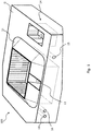
- FIG. 1 shows the geothermal plant 100 according to the present invention where the geothermal plant is integrated in a city environment to enable local heat delivery.
- the geothermal plant 100 comprises a bunker 11 established by digging into the ground the excavated soil having been used to create the bunker 11.
- the plant 100 provides an advantages effect of reducing the noise level generated by the geothermal plant as the bunker will function as a sound barrier in relation to the surrounding.
- By using the soil to build the bunker a minimum of soil will have to be removed during the installation of the geothermal plant.
- the height of the geothermal plant will depend on the height of the modules to be discussed further below.
- the minimum estimated area required for the geothermal plant would often be in the range of: 28-30 metres x 23-26 metres ⁇ 645-780 square meters, preferably 29 metres by 24 metres ⁇ 700 square meters.
- the present invention preferably in one embodiment is intended to appear as a bunker or as a cellar-construction to allow the geothermal plant to be arranged in an urban environment.
- the shown bunker 11 can include an access element in the form of an access door 12.
- the geothermal plant is connected to a geothermal well 14 located adjacent to the bunker 12 and to a transfer pipeline 15 for transferring discharged cold geothermal water.
- the geothermal well is covered by an access hatch to prevent personnel from falling into the well itself.
- a number district heating pine lines 16 and at least one transfer line 15 for the cold geothermal water are connected to the geothermal plant 100, 200.
- the district heating pipe line 16 will form part of an existing heat distribution network also referred to as a heat network and the present geothermal plant will be interconnected to the existing distribution network.
- heat storage units may be installed to even out peak load demands.
- the bunker 11 forms an exterior wall for the geothermal plant and the bunker surrounds removable modules, which are to be installed in the internal space formed by the soil removed during the construction of the bunker 11.
- the inner compartment 10 of the geothermal plant may as shown be formed by sheet piling driven into the ground, for providing an inner wall for obtaining stability prior to the step of accommodating the removable modules of the geothermal plant.
- the inner compartment 10 is formed by four inner walls 13, 13' positioned in a rectangular or quadric geometry and the four inner walls provide the necessary stiffening needed for supporting and preventing the bunker hill from collapsing towards the inner compartment 10.
- the inner compartment of the bunker 11 has in the shown embodiment a height h g of 7-13 m, preferably 9-11 m and the exterior height of the bunker relative to the ground level G is approximately 4-5 m, whereas the distance between two opposite inner walls is in the range of 11-15 meters, preferably 12-13 meters.
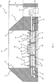
- Pipework 20 includes a first pipe assembly 22 comprising a first pipe system 25 being connectable to the geothermal well 14 at a first connecting end and a second pipe assembly 24, which is connectable to an existing facility pipework, also referred to as district heating pine lines 16.
- the first pipe assembly 22 is connectable to the geothermal well 14 through the use of at least two first interconnecting pipelines 23.
- the second pipe assembly 24 is connectable to the district heating pine lines 16 through the use of at least two second interconnecting pipelines 25.
- the pipework 20 furthermore comprises a number of connecting flanges 26,27 for enabling a connection between the module bays 30 and the removable modules (not shown in figure 2-3 ).
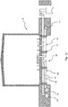
- the module bays 30 have a supporting structure 32 for supporting the removable modules and the supporting structures 31 includes a number of upright guide elements 34 being connected to the supporting structure 31.
- the supporting structure 32 is resting on a number of supporting element 29 arranged on the base element 28 positioned in the lower part of the inner compartment 10.
- the supporting structure provide the geothermal planet with a facility walkway for the personal operating the geothermal plant, but can also be used during service.
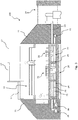
- the internal compartment 10 has a number of access hatches 17 in the upper part of the inner compartment 10, and the hatches 17 can be opened by pivoting the hatches, hereby providing access for the removable modules to be hoisted and lowered into the bunker 11.
- the removable modules 40 of the geothermal plant are connected to the pipework 20, which has been installed at the bottom of the inner compartment of the bunker prior to installing the removable modules in the geothermal plant. All pipework and cabling between the removable modules 40 and corresponding control equipment is arranged and runs below the supporting structure 32, whereby the supporting structure 32 functions as a walkway inside the geothermal plant (building) and thereby eases the installation and servicing of the facility equipment.
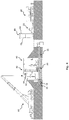
- the geothermal plant 100 (facility) is based on a modular design enabling the removable modules, preferably corresponding in size to or fitting into standard 6 or 12 meters intermodal freight containers, to be assembled off-site and then transported e.g. by a truck 50 to the installation site of the geothermal plant in a lying down position.
- a truck 50 to the installation site of the geothermal plant in a lying down position.
- the modules When the modules arrive, they are raised upright and installed vertically in the facility bunker with a hoisting unit 60 such as a mobile crane. After installation, the module transport frame is removed for allowing better access to the modules.
- each of the removable modules 40 may comprise a module transport frame 42,44 including a first module frame 42 forming a permanent module frame and a second module frame 44 being a removable transport frame (crash frame).
- a module transport frame which is removable it is possible to enable compact facility footprint.
- At least some of the removable modules 40 further comprise an electrical connections junction box positioned in the first module frame and a number of lifting eyes for hoisting the removable modules 40 during installation or service.
- the module components are mounted in vertical position for reducing the footprint of each of the removable modules.
- the removable modules 40 When the removable modules 40 are to be installed into the bunker facility, the modules are turned 90 degrees as can be seen in FIG. 4 .
- the models are hereafter lowered into the bunker facility.
- the installation can be done together with local contractors who can be quickly mobilized to perform the installation of the geothermal plant.
- the transport frame 44 is removed and the pipework 20 and electrical connections are interconnected to the equipment located inside the removable module.
- the removable modules 40 are fitted into the bunker facility 11 by using a number of upright module guides 46 which may be similar to those used for guiding freight containers on a container ship.
- the modules guides 46 provide an easy and precise installation of the removable modules 40 .
- Each of the modules would preferably have an installation foot-print of about 3x3 meters and a module height of about 6-12 meters depending on the facility.
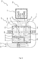
- the geothermal facility has a geothermal well 14 been formed as a dual well cellar, a geothermal heat production facility (depicted to the right) and a geothermal reinjection facility 90 comprising an injection pump module 92 depicted to the right side in the FIG. 7 .
- Each of the modules has a specific function and are interconnected, preferably exclusively at locations below the supporting structure.
- the shown geothermal facility includes nine individual equipment modules and a pipework being connected to a first district heating pipeline 161 for delivering heated water to the geothermal facility and a second district heating pipeline 162 for returning the water.
- the electronics and SCADA modules 301, 302 are located in a separate room 303 with HVAC.
- Pipework 20 between modules and electrical connections are located in a cellar below supporting structure forming the walkway grating and the removable modules.
- the removable modules are intended to be installed in a vertical position through the hatches in the upper part of the bunker 11.
- the other removable modules could be a compressor module 304, a condenser HEX 305, an evaporator HEX module 306, a pump module 307 for circulating the geothermal liquid, a pump module 308 for pumping the district heat water, a geothermal HEX module 309 and a filter unit module 310 for filtering the liquid being pump up from the underground.
- a geothermal plant 300 having an reinjection facility 302 is positioned at the vicinity of the geothermal heat exchanging 304.
- the geothermal well comprises a geothermal production line 94 and a geothermal injection line 96.
- the geothermal plant 300 comprises of 2 sets of 3 individual equipment modules - one for each well pair.
- the geothermal plant 300 includes nine individual equipment modules and a pipework connected to a first district heating pipeline 161 for delivering heated water to the geothermal facility and a second district heating pipeline 162 for returning the water.
- Pipework 20 between the modules and the electrical connections are located in the cellar below supporting structure forming the walkway grating and the removable modules, when the removable modules are installed in vertical position and installed/replaced through hatches in the upper part of the bunker 11.
- the electronics and SCADA modules 402 are located in a separate room 403 with HVAC.
- the other removable modules would be a pump module 401, a HEX module 404, an injection pump module 405, a HEX module 406, a pump module 407 for circulating the geothermal liquid, a heat transmission pump module 408, and two filter unit module 409, 410 for filtering the liquid being pump up from the underground.
- FIG. 9 shows a further embodiment of the geothermal plant having a horizontal dual compressors installed inside the bunker.
- Each of the removable modules having a compressor unit is arranged in a horizontal position.
- the geothermal plant 200 comprises a evaporator unit 202, a condensator unit 204 and a compressor unit 206.
- the compressor unit 206 will be hoisted down through the access hatch 208 positioned in the upper part of the geothermal plant and the compressor unit 206 will be lowered down into the internal through the bunker 11. It should be noted that the geothermal well is not depicted in the FIG. 9 for the sake of simplicity.
- the evaporator unit 202 will be placed on top of the condensator unit 204, which would be arranged between the evaporator unit 202 and the compressor unit 206.
- the evaporator unit 202 will be dual evaporator unit
- the condensator unit 204 will be a dual condensator unit type
- the compressor unit 206 will be a dual compressor unit.
- a number of module splitters/dividers 210 may divide the individual modules 20, 204 and 226.
- the distance between the access hatch and the module bays 30 with the pipe flanges may be in the range of 10-15 m.
- FIG. 10 shows an alternative implementation of the geothermal plant, where geothermal facility have the same components as shown in FIG. 2 , but with the difference that the bunker 11 is replaced by a conventional building wall structure or scaffold or the like.
- module bays depicted in the figures of the present invention is not divided into a number of separate module-bays, but us depicted as one single structure.
- the module-bays can be delivered as separate module-bay sections to be assembled at the geothermal installation site. By having a number of separate module-bay sections, it is easier to handle the module bays prior to a assembling step of the module-bays.
- Each of the module-bays is provided with means allowing the module-bays to be interconnected with one another.
Landscapes
- Engineering & Computer Science (AREA)
- General Engineering & Computer Science (AREA)
- Mechanical Engineering (AREA)
- Sustainable Development (AREA)
- Thermal Sciences (AREA)
- Life Sciences & Earth Sciences (AREA)
- Physics & Mathematics (AREA)
- Sustainable Energy (AREA)
- Chemical & Material Sciences (AREA)
- Combustion & Propulsion (AREA)
- Other Air-Conditioning Systems (AREA)
- Cultivation Of Plants (AREA)
- Fertilizers (AREA)
Claims (9)
- Installation géothermique (100,200,300) connectable à un puits géothermique (14) et comprenant au moins deux modules amovibles (40), au moins deux baies de modules (30) et une tuyauterie (20) :- au moins l'un desdits modules amovibles (40) comprenant un échangeur de chaleur ;- lesdites baies de module (30) comprenant une structure de support (32) supportant l'un respectif desdits modules amovibles (40) ;- ladite tuyauterie (20) comprenant un premier ensemble de tuyaux (22) pouvant être connecté à un premier système de tuyaux (23) dudit puits géothermique (14) à une première extrémité de connexion et un deuxième ensemble de tuyaux (24) pouvant être connecté à une tuyauterie d'installation existante (16) ;caractérisée en ce que
ladite tuyauterie (20) s'étend au-dessous de ladite structure de support (32) et
ladite ou lesdites baies de module (30) supportant ledit ou lesdits modules amovibles (40) comprenant un échangeur de chaleur sont munies d'une interface de connexion pour permettre audit au moins un module amovible comportant un échangeur de chaleur à connecter à ladite tuyauterie (20). - Installation géothermique selon la revendication 1, dans laquelle ladite installation géothermique comprend en outre un bunker (11) pour entourer les modules amovibles (40).
- Installation géothermique selon la revendication 1 ou 2, lesdits modules amovibles (40) étant divisés en un premier ensemble de modules amovibles et un deuxième ensemble de modules amovibles, ledit premier ensemble de modules amovibles (40) comprenant un échangeur de chaleur.
- Installation géothermique selon l'une quelconque des revendications précédentes, dans laquelle chacun desdits modules amovibles (40) comprend un cadre de transport de module comprenant un premier cadre de module (42) formant un cadre de module permanent et un deuxième cadre de module (44) étant un cadre de transport amovible.
- Installation géothermique selon l'une quelconque des revendications précédentes, ladite structure de support comprenant un certain nombre de guides de module verticaux (46) pour guider lesdits modules amovibles (40) lors de leur installation dans lesdites baies de module respectives (30).
- Installation géothermique selon l'une quelconque des revendications précédentes, ladite tuyauterie (20) comprenant un certain nombre de brides de raccordement (26,27).
- Installation géothermique selon la revendication 2, ladite installation comprenant en outre un certain nombre de trappes étant prévues à une première distance verticale au-dessus de ladite structure de support, de préférence dans la plage de 10 à 15 m.
- Installation géothermique selon l'une quelconque des revendications précédentes, ledit premier ensemble de tuyaux (22) comprenant une deuxième extrémité de connexion avec une première bride de raccordement étant située à l'extrémité opposée de ladite deuxième extrémité de connexion pour interconnecter ledit premier ensemble de tuyaux (22).
- Installation géothermique selon l'une quelconque des revendications précédentes, ledit puits géothermique comprend une ligne de production géothermique (94) et une ligne d'injection géothermique (96).
Priority Applications (2)
| Application Number | Priority Date | Filing Date | Title |
|---|---|---|---|
| PL19162822T PL3540331T3 (pl) | 2018-03-16 | 2019-03-14 | Siłownia geotermalna, którą można podłączyć do odwiertu geotermalnego |
| HRP20210081TT HRP20210081T1 (hr) | 2018-03-16 | 2021-01-18 | Geotermalno postrojenje koje se može povezati s geotermalnom bušotinom |
Applications Claiming Priority (1)
| Application Number | Priority Date | Filing Date | Title |
|---|---|---|---|
| DKPA201870171A DK180226B1 (en) | 2018-03-16 | 2018-03-16 | Geothermal plant that can be connected to a geothermal well |
Publications (3)
| Publication Number | Publication Date |
|---|---|
| EP3540331A1 EP3540331A1 (fr) | 2019-09-18 |
| EP3540331B1 true EP3540331B1 (fr) | 2020-11-04 |
| EP3540331B8 EP3540331B8 (fr) | 2020-12-23 |
Family
ID=65812202
Family Applications (1)
| Application Number | Title | Priority Date | Filing Date |
|---|---|---|---|
| EP19162822.1A Active EP3540331B8 (fr) | 2018-03-16 | 2019-03-14 | Installation géothermique connectable à un puit géothermique |
Country Status (6)
| Country | Link |
|---|---|
| EP (1) | EP3540331B8 (fr) |
| DK (1) | DK180226B1 (fr) |
| ES (1) | ES2847573T3 (fr) |
| HR (1) | HRP20210081T1 (fr) |
| HU (1) | HUE052438T2 (fr) |
| PL (1) | PL3540331T3 (fr) |
Cited By (13)
| Publication number | Priority date | Publication date | Assignee | Title |
|---|---|---|---|---|
| US11480074B1 (en) | 2021-04-02 | 2022-10-25 | Ice Thermal Harvesting, Llc | Systems and methods utilizing gas temperature as a power source |
| US11486370B2 (en) | 2021-04-02 | 2022-11-01 | Ice Thermal Harvesting, Llc | Modular mobile heat generation unit for generation of geothermal power in organic Rankine cycle operations |
| US11486330B2 (en) | 2021-04-02 | 2022-11-01 | Ice Thermal Harvesting, Llc | Systems and methods utilizing gas temperature as a power source |
| US11493029B2 (en) | 2021-04-02 | 2022-11-08 | Ice Thermal Harvesting, Llc | Systems and methods for generation of electrical power at a drilling rig |
| US11578706B2 (en) | 2021-04-02 | 2023-02-14 | Ice Thermal Harvesting, Llc | Systems for generating geothermal power in an organic Rankine cycle operation during hydrocarbon production based on wellhead fluid temperature |
| US11592009B2 (en) | 2021-04-02 | 2023-02-28 | Ice Thermal Harvesting, Llc | Systems and methods for generation of electrical power at a drilling rig |
| US11644015B2 (en) | 2021-04-02 | 2023-05-09 | Ice Thermal Harvesting, Llc | Systems and methods for generation of electrical power at a drilling rig |
| US11644014B2 (en) | 2021-04-02 | 2023-05-09 | Ice Thermal Harvesting, Llc | Systems and methods for generation of electrical power in an organic Rankine cycle operation |
| US11959466B2 (en) | 2021-04-02 | 2024-04-16 | Ice Thermal Harvesting, Llc | Systems and methods for generation of electrical power in an organic Rankine cycle operation |
| US12180861B1 (en) | 2022-12-30 | 2024-12-31 | Ice Thermal Harvesting, Llc | Systems and methods to utilize heat carriers in conversion of thermal energy |
| US12312981B2 (en) | 2021-04-02 | 2025-05-27 | Ice Thermal Harvesting, Llc | Systems and methods utilizing gas temperature as a power source |
| US12534990B2 (en) | 2022-12-29 | 2026-01-27 | Ice Thermal Harvesting, Llc | Power generation assemblies for hydraulic fracturing systems and methods |
| US12578124B2 (en) | 2018-08-29 | 2026-03-17 | Waterfurnace International, Inc. | Integrated demand water heating using a capacity modulated heat pump with desuperheater |
Families Citing this family (1)
| Publication number | Priority date | Publication date | Assignee | Title |
|---|---|---|---|---|
| CN114776377B (zh) * | 2022-05-31 | 2025-06-27 | 山东省鲁南地质工程勘察院(山东省地质矿产勘查开发局第二地质大队) | 一种采煤塌陷地的支撑装置及地热利用系统和利用方法 |
Citations (1)
| Publication number | Priority date | Publication date | Assignee | Title |
|---|---|---|---|---|
| US20120111004A1 (en) * | 2010-11-10 | 2012-05-10 | Conry Ronald D | Modular energy harvesting system |
Family Cites Families (6)
| Publication number | Priority date | Publication date | Assignee | Title |
|---|---|---|---|---|
| NZ248730A (en) * | 1992-10-02 | 1996-03-26 | Ormat Ind Ltd | High pressure geothermal power plant with primary steam turbine and at least one power plant module having low pressure turbine |
| US20100132390A1 (en) | 2008-09-18 | 2010-06-03 | Multistack Llc | Variable four pipe heatpump chiller |
| US20110224942A1 (en) * | 2010-03-11 | 2011-09-15 | Kidwell John E | GPS-tracking ground heat exchanger (GHE) performance test instrumentation network supporting a plurality of wireless portable GPS-based enthalpy-based GHE performance test instrumentation systems |
| US9677778B2 (en) * | 2010-04-20 | 2017-06-13 | Climacool Corp. | Modular chiller unit with dedicated cooling and heating fluid circuits and system comprising a plurality of such units |
| US9562708B2 (en) * | 2012-12-03 | 2017-02-07 | Waterfurnace International, Inc. | Conduit module coupled with heating or cooling module |
| US9091460B2 (en) * | 2013-03-21 | 2015-07-28 | Gtherm, Inc. | System and a method of operating a plurality of geothermal heat extraction borehole wells |
-
2018
- 2018-03-16 DK DKPA201870171A patent/DK180226B1/en active IP Right Grant
-
2019
- 2019-03-14 ES ES19162822T patent/ES2847573T3/es active Active
- 2019-03-14 HU HUE19162822A patent/HUE052438T2/hu unknown
- 2019-03-14 EP EP19162822.1A patent/EP3540331B8/fr active Active
- 2019-03-14 PL PL19162822T patent/PL3540331T3/pl unknown
-
2021
- 2021-01-18 HR HRP20210081TT patent/HRP20210081T1/hr unknown
Patent Citations (1)
| Publication number | Priority date | Publication date | Assignee | Title |
|---|---|---|---|---|
| US20120111004A1 (en) * | 2010-11-10 | 2012-05-10 | Conry Ronald D | Modular energy harvesting system |
Cited By (41)
| Publication number | Priority date | Publication date | Assignee | Title |
|---|---|---|---|---|
| US12578124B2 (en) | 2018-08-29 | 2026-03-17 | Waterfurnace International, Inc. | Integrated demand water heating using a capacity modulated heat pump with desuperheater |
| US11905934B2 (en) | 2021-04-02 | 2024-02-20 | Ice Thermal Harvesting, Llc | Systems and methods for generation of electrical power at a drilling rig |
| US11732697B2 (en) | 2021-04-02 | 2023-08-22 | Ice Thermal Harvesting, Llc | Systems for generating geothermal power in an organic Rankine cycle operation during hydrocarbon production based on wellhead fluid temperature |
| US11493029B2 (en) | 2021-04-02 | 2022-11-08 | Ice Thermal Harvesting, Llc | Systems and methods for generation of electrical power at a drilling rig |
| US11542888B2 (en) | 2021-04-02 | 2023-01-03 | Ice Thermal Harvesting, Llc | Systems and methods utilizing gas temperature as a power source |
| US11549402B2 (en) | 2021-04-02 | 2023-01-10 | Ice Thermal Harvesting, Llc | Systems and methods utilizing gas temperature as a power source |
| US11572849B1 (en) | 2021-04-02 | 2023-02-07 | Ice Thermal Harvesting, Llc | Systems and methods utilizing gas temperature as a power source |
| US11578706B2 (en) | 2021-04-02 | 2023-02-14 | Ice Thermal Harvesting, Llc | Systems for generating geothermal power in an organic Rankine cycle operation during hydrocarbon production based on wellhead fluid temperature |
| US11592009B2 (en) | 2021-04-02 | 2023-02-28 | Ice Thermal Harvesting, Llc | Systems and methods for generation of electrical power at a drilling rig |
| US11598320B2 (en) | 2021-04-02 | 2023-03-07 | Ice Thermal Harvesting, Llc | Systems and methods for generation of electrical power at a drilling rig |
| US11624355B2 (en) | 2021-04-02 | 2023-04-11 | Ice Thermal Harvesting, Llc | Modular mobile heat generation unit for generation of geothermal power in organic Rankine cycle operations |
| US11644015B2 (en) | 2021-04-02 | 2023-05-09 | Ice Thermal Harvesting, Llc | Systems and methods for generation of electrical power at a drilling rig |
| US11644014B2 (en) | 2021-04-02 | 2023-05-09 | Ice Thermal Harvesting, Llc | Systems and methods for generation of electrical power in an organic Rankine cycle operation |
| US11668209B2 (en) | 2021-04-02 | 2023-06-06 | Ice Thermal Harvesting, Llc | Systems and methods utilizing gas temperature as a power source |
| US11680541B2 (en) | 2021-04-02 | 2023-06-20 | Ice Thermal Harvesting, Llc | Systems and methods utilizing gas temperature as a power source |
| US11480074B1 (en) | 2021-04-02 | 2022-10-25 | Ice Thermal Harvesting, Llc | Systems and methods utilizing gas temperature as a power source |
| US11761353B2 (en) | 2021-04-02 | 2023-09-19 | Ice Thermal Harvesting, Llc | Systems and methods utilizing gas temperature as a power source |
| US11761433B2 (en) | 2021-04-02 | 2023-09-19 | Ice Thermal Harvesting, Llc | Systems and methods for generation of electrical power in an organic Rankine cycle operation |
| US11773805B2 (en) | 2021-04-02 | 2023-10-03 | Ice Thermal Harvesting, Llc | Systems and methods utilizing gas temperature as a power source |
| US11486330B2 (en) | 2021-04-02 | 2022-11-01 | Ice Thermal Harvesting, Llc | Systems and methods utilizing gas temperature as a power source |
| US11879409B2 (en) | 2021-04-02 | 2024-01-23 | Ice Thermal Harvesting, Llc | Systems and methods utilizing gas temperature as a power source |
| US12049875B2 (en) | 2021-04-02 | 2024-07-30 | Ice Thermal Harvesting, Llc | Systems and methods for generation of electrical power in an organic Rankine cycle operation |
| US11933279B2 (en) | 2021-04-02 | 2024-03-19 | Ice Thermal Harvesting, Llc | Systems and methods for generation of electrical power at a drilling rig |
| US11946459B2 (en) | 2021-04-02 | 2024-04-02 | Ice Thermal Harvesting, Llc | Systems and methods for generation of electrical power at a drilling rig |
| US11959466B2 (en) | 2021-04-02 | 2024-04-16 | Ice Thermal Harvesting, Llc | Systems and methods for generation of electrical power in an organic Rankine cycle operation |
| US11971019B2 (en) | 2021-04-02 | 2024-04-30 | Ice Thermal Harvesting, Llc | Systems for generating geothermal power in an organic Rankine cycle operation during hydrocarbon production based on wellhead fluid temperature |
| US11933280B2 (en) | 2021-04-02 | 2024-03-19 | Ice Thermal Harvesting, Llc | Modular mobile heat generation unit for generation of geothermal power in organic Rankine cycle operations |
| US12060867B2 (en) | 2021-04-02 | 2024-08-13 | Ice Thermal Harvesting, Llc | Systems for generating geothermal power in an organic Rankine cycle operation during hydrocarbon production based on working fluid temperature |
| US12104553B2 (en) | 2021-04-02 | 2024-10-01 | Ice Thermal Harvesting, Llc | Systems and methods utilizing gas temperature as a power source |
| US12110878B2 (en) | 2021-04-02 | 2024-10-08 | Ice Thermal Harvesting, Llc | Systems and methods for generation of electrical power at a drilling rig |
| US12135016B2 (en) | 2021-04-02 | 2024-11-05 | Ice Thermal Harvesting, Llc | Systems for generating geothermal power in an organic Rankine cycle operation during hydrocarbon production based on wellhead fluid temperature |
| US12140124B2 (en) | 2021-04-02 | 2024-11-12 | Ice Thermal Harvesting, Llc | Systems and methods for generation of electrical power at a drilling rig |
| US12146475B2 (en) | 2021-04-02 | 2024-11-19 | Ice Thermal Harvesting, Llc | Systems and methods for generation of electrical power in an organic rankine cycle operation |
| US12163485B2 (en) | 2021-04-02 | 2024-12-10 | Ice Thermal Harvesting, Llc | Systems and methods utilizing gas temperature as a power source |
| US11486370B2 (en) | 2021-04-02 | 2022-11-01 | Ice Thermal Harvesting, Llc | Modular mobile heat generation unit for generation of geothermal power in organic Rankine cycle operations |
| US12305624B2 (en) | 2021-04-02 | 2025-05-20 | Ice Thermal Harvesting, Llc | Modular mobile heat generation unit for generation of geothermal power in organic rankine cycle operations |
| US12312981B2 (en) | 2021-04-02 | 2025-05-27 | Ice Thermal Harvesting, Llc | Systems and methods utilizing gas temperature as a power source |
| US12385474B2 (en) | 2021-04-02 | 2025-08-12 | Ice Thermal Harvesting, Llc | Systems for generating geothermal power in an organic Rankine cycle operation during hydrocarbon production based on working fluid temperature |
| US12454896B2 (en) | 2021-04-02 | 2025-10-28 | Ice Thermal Harvesting, Llc | Systems and methods utilizing gas temperature as a power source |
| US12534990B2 (en) | 2022-12-29 | 2026-01-27 | Ice Thermal Harvesting, Llc | Power generation assemblies for hydraulic fracturing systems and methods |
| US12180861B1 (en) | 2022-12-30 | 2024-12-31 | Ice Thermal Harvesting, Llc | Systems and methods to utilize heat carriers in conversion of thermal energy |
Also Published As
| Publication number | Publication date |
|---|---|
| DK201870171A1 (en) | 2019-09-26 |
| HUE052438T2 (hu) | 2021-04-28 |
| HRP20210081T1 (hr) | 2021-03-05 |
| DK180226B1 (en) | 2020-08-24 |
| ES2847573T3 (es) | 2021-08-03 |
| EP3540331B8 (fr) | 2020-12-23 |
| EP3540331A1 (fr) | 2019-09-18 |
| PL3540331T3 (pl) | 2021-05-17 |
Similar Documents
| Publication | Publication Date | Title |
|---|---|---|
| EP3540331B1 (fr) | Installation géothermique connectable à un puit géothermique | |
| US6644342B1 (en) | Modular integrated wastewater lift station construction kit | |
| US12180730B2 (en) | Hybrid building system, building and method | |
| US20200146186A1 (en) | Modular data center with horizontal air flow | |
| US20090000243A1 (en) | Data center | |
| US11649615B2 (en) | Lifeline system for compact house | |
| GB2216868A (en) | Lift assembly. | |
| WO2018044396A1 (fr) | Installation de compression modulaire | |
| EP4286755B1 (fr) | Logement pompe a chaleur | |
| FI3149821T3 (fi) | Ulkoinen taloliittymätila taloliittymän muodostamiseksi | |
| US6939081B1 (en) | Fuel dispensing and containment assembly | |
| CN204608945U (zh) | 箱底排水结构、集装箱模块化淋浴间及集装箱模块化建筑 | |
| US20030156902A1 (en) | Fuel dispensing and containment assembly | |
| EP1208278A1 (fr) | Station de lavage de voiture | |
| US20140283470A1 (en) | Prefabricated walls for temporary housing applications | |
| CN209652977U (zh) | 一种复合型缆线管廊 | |
| CN206207526U (zh) | 移动撬装式换热站 | |
| JPH09292484A (ja) | 原子力発電設備 | |
| JPH05196265A (ja) | 鋼管柱列土留壁を利用した空気調和設備用蓄熱装置 |
Legal Events
| Date | Code | Title | Description |
|---|---|---|---|
| PUAI | Public reference made under article 153(3) epc to a published international application that has entered the european phase |
Free format text: ORIGINAL CODE: 0009012 |
|
| STAA | Information on the status of an ep patent application or granted ep patent |
Free format text: STATUS: THE APPLICATION HAS BEEN PUBLISHED |
|
| AK | Designated contracting states |
Kind code of ref document: A1 Designated state(s): AL AT BE BG CH CY CZ DE DK EE ES FI FR GB GR HR HU IE IS IT LI LT LU LV MC MK MT NL NO PL PT RO RS SE SI SK SM TR |
|
| AX | Request for extension of the european patent |
Extension state: BA ME |
|
| STAA | Information on the status of an ep patent application or granted ep patent |
Free format text: STATUS: REQUEST FOR EXAMINATION WAS MADE |
|
| 17P | Request for examination filed |
Effective date: 20191009 |
|
| RBV | Designated contracting states (corrected) |
Designated state(s): AL AT BE BG CH CY CZ DE DK EE ES FI FR GB GR HR HU IE IS IT LI LT LU LV MC MK MT NL NO PL PT RO RS SE SI SK SM TR |
|
| RIN1 | Information on inventor provided before grant (corrected) |
Inventor name: KASTER, MARTIN |
|
| GRAP | Despatch of communication of intention to grant a patent |
Free format text: ORIGINAL CODE: EPIDOSNIGR1 |
|
| STAA | Information on the status of an ep patent application or granted ep patent |
Free format text: STATUS: GRANT OF PATENT IS INTENDED |
|
| RIC1 | Information provided on ipc code assigned before grant |
Ipc: F24T 10/00 20180101AFI20200519BHEP |
|
| INTG | Intention to grant announced |
Effective date: 20200619 |
|
| GRAS | Grant fee paid |
Free format text: ORIGINAL CODE: EPIDOSNIGR3 |
|
| GRAA | (expected) grant |
Free format text: ORIGINAL CODE: 0009210 |
|
| STAA | Information on the status of an ep patent application or granted ep patent |
Free format text: STATUS: THE PATENT HAS BEEN GRANTED |
|
| AK | Designated contracting states |
Kind code of ref document: B1 Designated state(s): AL AT BE BG CH CY CZ DE DK EE ES FI FR GB GR HR HU IE IS IT LI LT LU LV MC MK MT NL NO PL PT RO RS SE SI SK SM TR |
|
| REG | Reference to a national code |
Ref country code: GB Ref legal event code: FG4D |
|
| REG | Reference to a national code |
Ref country code: CH Ref legal event code: EP |
|
| REG | Reference to a national code |
Ref country code: AT Ref legal event code: REF Ref document number: 1331355 Country of ref document: AT Kind code of ref document: T Effective date: 20201115 |
|
| RAP2 | Party data changed (patent owner data changed or rights of a patent transferred) |
Owner name: APMH INVEST IV A/S |
|
| REG | Reference to a national code |
Ref country code: IE Ref legal event code: FG4D |
|
| REG | Reference to a national code |
Ref country code: DE Ref legal event code: R096 Ref document number: 602019001149 Country of ref document: DE |
|
| REG | Reference to a national code |
Ref country code: CH Ref legal event code: PK Free format text: BERICHTIGUNG B8 |
|
| REG | Reference to a national code |
Ref country code: HR Ref legal event code: TUEP Ref document number: P20210081 Country of ref document: HR |
|
| REG | Reference to a national code |
Ref country code: SE Ref legal event code: TRGR |
|
| REG | Reference to a national code |
Ref country code: NL Ref legal event code: FP |
|
| REG | Reference to a national code |
Ref country code: HR Ref legal event code: T1PR Ref document number: P20210081 Country of ref document: HR |
|
| REG | Reference to a national code |
Ref country code: HR Ref legal event code: ODRP Ref document number: P20210081 Country of ref document: HR Payment date: 20210218 Year of fee payment: 3 |
|
| REG | Reference to a national code |
Ref country code: SK Ref legal event code: T3 Ref document number: E 36393 Country of ref document: SK |
|
| REG | Reference to a national code |
Ref country code: HU Ref legal event code: AG4A Ref document number: E052438 Country of ref document: HU |
|
| PG25 | Lapsed in a contracting state [announced via postgrant information from national office to epo] |
Ref country code: GR Free format text: LAPSE BECAUSE OF FAILURE TO SUBMIT A TRANSLATION OF THE DESCRIPTION OR TO PAY THE FEE WITHIN THE PRESCRIBED TIME-LIMIT Effective date: 20210205 Ref country code: NO Free format text: LAPSE BECAUSE OF FAILURE TO SUBMIT A TRANSLATION OF THE DESCRIPTION OR TO PAY THE FEE WITHIN THE PRESCRIBED TIME-LIMIT Effective date: 20210204 Ref country code: PT Free format text: LAPSE BECAUSE OF FAILURE TO SUBMIT A TRANSLATION OF THE DESCRIPTION OR TO PAY THE FEE WITHIN THE PRESCRIBED TIME-LIMIT Effective date: 20210304 Ref country code: RS Free format text: LAPSE BECAUSE OF FAILURE TO SUBMIT A TRANSLATION OF THE DESCRIPTION OR TO PAY THE FEE WITHIN THE PRESCRIBED TIME-LIMIT Effective date: 20201104 Ref country code: FI Free format text: LAPSE BECAUSE OF FAILURE TO SUBMIT A TRANSLATION OF THE DESCRIPTION OR TO PAY THE FEE WITHIN THE PRESCRIBED TIME-LIMIT Effective date: 20201104 |
|
| PG25 | Lapsed in a contracting state [announced via postgrant information from national office to epo] |
Ref country code: LV Free format text: LAPSE BECAUSE OF FAILURE TO SUBMIT A TRANSLATION OF THE DESCRIPTION OR TO PAY THE FEE WITHIN THE PRESCRIBED TIME-LIMIT Effective date: 20201104 Ref country code: BG Free format text: LAPSE BECAUSE OF FAILURE TO SUBMIT A TRANSLATION OF THE DESCRIPTION OR TO PAY THE FEE WITHIN THE PRESCRIBED TIME-LIMIT Effective date: 20210204 |
|
| REG | Reference to a national code |
Ref country code: LT Ref legal event code: MG9D |
|
| PG25 | Lapsed in a contracting state [announced via postgrant information from national office to epo] |
Ref country code: LT Free format text: LAPSE BECAUSE OF FAILURE TO SUBMIT A TRANSLATION OF THE DESCRIPTION OR TO PAY THE FEE WITHIN THE PRESCRIBED TIME-LIMIT Effective date: 20201104 Ref country code: RO Free format text: LAPSE BECAUSE OF FAILURE TO SUBMIT A TRANSLATION OF THE DESCRIPTION OR TO PAY THE FEE WITHIN THE PRESCRIBED TIME-LIMIT Effective date: 20201104 Ref country code: EE Free format text: LAPSE BECAUSE OF FAILURE TO SUBMIT A TRANSLATION OF THE DESCRIPTION OR TO PAY THE FEE WITHIN THE PRESCRIBED TIME-LIMIT Effective date: 20201104 Ref country code: SM Free format text: LAPSE BECAUSE OF FAILURE TO SUBMIT A TRANSLATION OF THE DESCRIPTION OR TO PAY THE FEE WITHIN THE PRESCRIBED TIME-LIMIT Effective date: 20201104 |
|
| REG | Reference to a national code |
Ref country code: ES Ref legal event code: FG2A Ref document number: 2847573 Country of ref document: ES Kind code of ref document: T3 Effective date: 20210803 |
|
| REG | Reference to a national code |
Ref country code: DE Ref legal event code: R097 Ref document number: 602019001149 Country of ref document: DE |
|
| PG25 | Lapsed in a contracting state [announced via postgrant information from national office to epo] |
Ref country code: DK Free format text: LAPSE BECAUSE OF FAILURE TO SUBMIT A TRANSLATION OF THE DESCRIPTION OR TO PAY THE FEE WITHIN THE PRESCRIBED TIME-LIMIT Effective date: 20201104 |
|
| PLBE | No opposition filed within time limit |
Free format text: ORIGINAL CODE: 0009261 |
|
| STAA | Information on the status of an ep patent application or granted ep patent |
Free format text: STATUS: NO OPPOSITION FILED WITHIN TIME LIMIT |
|
| 26N | No opposition filed |
Effective date: 20210805 |
|
| PG25 | Lapsed in a contracting state [announced via postgrant information from national office to epo] |
Ref country code: MC Free format text: LAPSE BECAUSE OF FAILURE TO SUBMIT A TRANSLATION OF THE DESCRIPTION OR TO PAY THE FEE WITHIN THE PRESCRIBED TIME-LIMIT Effective date: 20201104 Ref country code: AL Free format text: LAPSE BECAUSE OF FAILURE TO SUBMIT A TRANSLATION OF THE DESCRIPTION OR TO PAY THE FEE WITHIN THE PRESCRIBED TIME-LIMIT Effective date: 20201104 |
|
| PG25 | Lapsed in a contracting state [announced via postgrant information from national office to epo] |
Ref country code: SI Free format text: LAPSE BECAUSE OF FAILURE TO SUBMIT A TRANSLATION OF THE DESCRIPTION OR TO PAY THE FEE WITHIN THE PRESCRIBED TIME-LIMIT Effective date: 20201104 |
|
| PG25 | Lapsed in a contracting state [announced via postgrant information from national office to epo] |
Ref country code: IE Free format text: LAPSE BECAUSE OF NON-PAYMENT OF DUE FEES Effective date: 20210314 |
|
| REG | Reference to a national code |
Ref country code: HR Ref legal event code: ODRP Ref document number: P20210081 Country of ref document: HR Payment date: 20220216 Year of fee payment: 4 |
|
| REG | Reference to a national code |
Ref country code: LU Ref legal event code: HC Owner name: INNARGI A/S; DK Free format text: FORMER OWNER: APMH INVEST IV A/S Effective date: 20220414 |
|
| REG | Reference to a national code |
Ref country code: NL Ref legal event code: PD Owner name: APMH INVEST IV A/S; DK Free format text: DETAILS ASSIGNMENT: CHANGE OF OWNER(S), CHANGE OF LEGAL ENTITY; FORMER OWNER NAME: APMH INVEST IV APS Effective date: 20220422 Ref country code: NL Ref legal event code: HC Owner name: INNARGI A/S; DK Free format text: DETAILS ASSIGNMENT: CHANGE OF OWNER(S), CHANGE OF OWNER(S) NAME; FORMER OWNER NAME: APMH INVEST IV A/S Effective date: 20220422 |
|
| REG | Reference to a national code |
Ref country code: HR Ref legal event code: PNAN Ref document number: P20210081 Country of ref document: HR Owner name: INNARGI A/S, DK |
|
| REG | Reference to a national code |
Ref country code: SK Ref legal event code: TC4A Ref document number: E 36393 Country of ref document: SK Owner name: INNARGI A/S, 2800 KONGENS LYNGBY, DK Effective date: 20220601 |
|
| REG | Reference to a national code |
Ref country code: DE Ref legal event code: R081 Ref document number: 602019001149 Country of ref document: DE Owner name: INNARGI A/S, DK Free format text: FORMER OWNER: APMH INVEST IV APS, KOEBENHAVN, DK Ref country code: BE Ref legal event code: HC Owner name: INNARGI A/S; DK Free format text: DETAILS ASSIGNMENT: CHANGE OF OWNER(S), CHANGE OF OWNER(S) NAME; FORMER OWNER NAME: APMH INVEST IV A/S Effective date: 20220524 |
|
| REG | Reference to a national code |
Ref country code: AT Ref legal event code: HC Ref document number: 1331355 Country of ref document: AT Kind code of ref document: T Owner name: INNARGI A/S, DK Effective date: 20220621 |
|
| REG | Reference to a national code |
Ref country code: ES Ref legal event code: PC2A Owner name: INNARGI A/S Effective date: 20220822 |
|
| REG | Reference to a national code |
Ref country code: HR Ref legal event code: ODRP Ref document number: P20210081 Country of ref document: HR Payment date: 20230214 Year of fee payment: 5 |
|
| PG25 | Lapsed in a contracting state [announced via postgrant information from national office to epo] |
Ref country code: CY Free format text: LAPSE BECAUSE OF FAILURE TO SUBMIT A TRANSLATION OF THE DESCRIPTION OR TO PAY THE FEE WITHIN THE PRESCRIBED TIME-LIMIT Effective date: 20201104 |
|
| REG | Reference to a national code |
Ref country code: HR Ref legal event code: ODRP Ref document number: P20210081 Country of ref document: HR Payment date: 20240130 Year of fee payment: 6 |
|
| PG25 | Lapsed in a contracting state [announced via postgrant information from national office to epo] |
Ref country code: MK Free format text: LAPSE BECAUSE OF FAILURE TO SUBMIT A TRANSLATION OF THE DESCRIPTION OR TO PAY THE FEE WITHIN THE PRESCRIBED TIME-LIMIT Effective date: 20201104 |
|
| PGFP | Annual fee paid to national office [announced via postgrant information from national office to epo] |
Ref country code: ES Payment date: 20240522 Year of fee payment: 6 |
|
| PG25 | Lapsed in a contracting state [announced via postgrant information from national office to epo] |
Ref country code: MT Free format text: LAPSE BECAUSE OF FAILURE TO SUBMIT A TRANSLATION OF THE DESCRIPTION OR TO PAY THE FEE WITHIN THE PRESCRIBED TIME-LIMIT Effective date: 20201104 |
|
| PGFP | Annual fee paid to national office [announced via postgrant information from national office to epo] |
Ref country code: NL Payment date: 20250122 Year of fee payment: 7 Ref country code: LU Payment date: 20250102 Year of fee payment: 7 |
|
| REG | Reference to a national code |
Ref country code: HR Ref legal event code: ODRP Ref document number: P20210081 Country of ref document: HR Payment date: 20250120 Year of fee payment: 7 |
|
| PGFP | Annual fee paid to national office [announced via postgrant information from national office to epo] |
Ref country code: DE Payment date: 20250224 Year of fee payment: 7 Ref country code: HR Payment date: 20250120 Year of fee payment: 7 Ref country code: IS Payment date: 20250217 Year of fee payment: 7 |
|
| REG | Reference to a national code |
Ref country code: AT Ref legal event code: UEP Ref document number: 1331355 Country of ref document: AT Kind code of ref document: T Effective date: 20201104 |
|
| PGFP | Annual fee paid to national office [announced via postgrant information from national office to epo] |
Ref country code: HU Payment date: 20250116 Year of fee payment: 7 |
|
| PGFP | Annual fee paid to national office [announced via postgrant information from national office to epo] |
Ref country code: SE Payment date: 20250122 Year of fee payment: 7 |
|
| PGFP | Annual fee paid to national office [announced via postgrant information from national office to epo] |
Ref country code: AT Payment date: 20250219 Year of fee payment: 7 Ref country code: BE Payment date: 20250121 Year of fee payment: 7 |
|
| PGFP | Annual fee paid to national office [announced via postgrant information from national office to epo] |
Ref country code: FR Payment date: 20250123 Year of fee payment: 7 Ref country code: CZ Payment date: 20250115 Year of fee payment: 7 Ref country code: PL Payment date: 20250221 Year of fee payment: 7 |
|
| PGFP | Annual fee paid to national office [announced via postgrant information from national office to epo] |
Ref country code: IT Payment date: 20250217 Year of fee payment: 7 Ref country code: SK Payment date: 20250217 Year of fee payment: 7 Ref country code: GB Payment date: 20250120 Year of fee payment: 7 |
|
| PGFP | Annual fee paid to national office [announced via postgrant information from national office to epo] |
Ref country code: CH Payment date: 20250401 Year of fee payment: 7 |
|
| PG25 | Lapsed in a contracting state [announced via postgrant information from national office to epo] |
Ref country code: TR Free format text: LAPSE BECAUSE OF FAILURE TO SUBMIT A TRANSLATION OF THE DESCRIPTION OR TO PAY THE FEE WITHIN THE PRESCRIBED TIME-LIMIT Effective date: 20201104 |
|
| REG | Reference to a national code |
Ref country code: ES Ref legal event code: FD2A Effective date: 20260428 |