EP3540430A2 - Vorrichtung und verfahren zur auswertung der ansprechzeit eines gassensors - Google Patents
Vorrichtung und verfahren zur auswertung der ansprechzeit eines gassensors Download PDFInfo
- Publication number
- EP3540430A2 EP3540430A2 EP19160195.4A EP19160195A EP3540430A2 EP 3540430 A2 EP3540430 A2 EP 3540430A2 EP 19160195 A EP19160195 A EP 19160195A EP 3540430 A2 EP3540430 A2 EP 3540430A2
- Authority
- EP
- European Patent Office
- Prior art keywords
- gas
- pipe
- valve
- connecting pipe
- supply
- Prior art date
- Legal status (The legal status is an assumption and is not a legal conclusion. Google has not performed a legal analysis and makes no representation as to the accuracy of the status listed.)
- Granted
Links
Images


Classifications
-
- G—PHYSICS
- G01—MEASURING; TESTING
- G01N—INVESTIGATING OR ANALYSING MATERIALS BY DETERMINING THEIR CHEMICAL OR PHYSICAL PROPERTIES
- G01N33/00—Investigating or analysing materials by specific methods not covered by groups G01N1/00 - G01N31/00
- G01N33/0004—Gaseous mixtures, e.g. polluted air
- G01N33/0009—General constructional details of gas analysers, e.g. portable test equipment
- G01N33/0027—General constructional details of gas analysers, e.g. portable test equipment concerning the detector
- G01N33/0036—General constructional details of gas analysers, e.g. portable test equipment concerning the detector specially adapted to detect a particular component
- G01N33/0037—NOx
-
- G—PHYSICS
- G01—MEASURING; TESTING
- G01N—INVESTIGATING OR ANALYSING MATERIALS BY DETERMINING THEIR CHEMICAL OR PHYSICAL PROPERTIES
- G01N33/00—Investigating or analysing materials by specific methods not covered by groups G01N1/00 - G01N31/00
- G01N33/0004—Gaseous mixtures, e.g. polluted air
- G01N33/0009—General constructional details of gas analysers, e.g. portable test equipment
- G01N33/007—Arrangements to check the analyser
-
- G—PHYSICS
- G01—MEASURING; TESTING
- G01N—INVESTIGATING OR ANALYSING MATERIALS BY DETERMINING THEIR CHEMICAL OR PHYSICAL PROPERTIES
- G01N33/00—Investigating or analysing materials by specific methods not covered by groups G01N1/00 - G01N31/00
- G01N33/0004—Gaseous mixtures, e.g. polluted air
- G01N33/0009—General constructional details of gas analysers, e.g. portable test equipment
- G01N33/0027—General constructional details of gas analysers, e.g. portable test equipment concerning the detector
- G01N33/0036—General constructional details of gas analysers, e.g. portable test equipment concerning the detector specially adapted to detect a particular component
- G01N33/0054—Ammonia
-
- G—PHYSICS
- G01—MEASURING; TESTING
- G01N—INVESTIGATING OR ANALYSING MATERIALS BY DETERMINING THEIR CHEMICAL OR PHYSICAL PROPERTIES
- G01N33/00—Investigating or analysing materials by specific methods not covered by groups G01N1/00 - G01N31/00
- G01N33/0004—Gaseous mixtures, e.g. polluted air
- G01N33/0009—General constructional details of gas analysers, e.g. portable test equipment
- G01N33/007—Arrangements to check the analyser
- G01N33/0072—Arrangements to check the analyser by generating a test gas
-
- Y—GENERAL TAGGING OF NEW TECHNOLOGICAL DEVELOPMENTS; GENERAL TAGGING OF CROSS-SECTIONAL TECHNOLOGIES SPANNING OVER SEVERAL SECTIONS OF THE IPC; TECHNICAL SUBJECTS COVERED BY FORMER USPC CROSS-REFERENCE ART COLLECTIONS [XRACs] AND DIGESTS
- Y02—TECHNOLOGIES OR APPLICATIONS FOR MITIGATION OR ADAPTATION AGAINST CLIMATE CHANGE
- Y02A—TECHNOLOGIES FOR ADAPTATION TO CLIMATE CHANGE
- Y02A50/00—TECHNOLOGIES FOR ADAPTATION TO CLIMATE CHANGE in human health protection, e.g. against extreme weather
- Y02A50/20—Air quality improvement or preservation, e.g. vehicle emission control or emission reduction by using catalytic converters
Definitions
- the present invention relates to a gas sensor response time evaluating apparatus and method for evaluating a response time of gas sensors.
- Patent Document 1 discloses that a plurality of gases whose flow rates are controlled by a mass flow controller are mixed by means of a mixing device to generate a mixed gas.
- the mixed gas is supplied to a gas sensor(s) to be tested.
- the flow rate of each gas is adjusted by the mass flow controller to change a mixing ratio of each gas, whereby a response characteristic and the like of the gas sensor(s) can be evaluated.
- Patent Document 2 discloses that a tip portion of a gas sensor attached to a chamber is covered with a cap. When the tip of the gas sensor is covered with the cap, an atmosphere in the cap is different from that in the chamber. By releasing the covering with the cap, the atmosphere around the gas sensor is instantly switched. By switching the atmosphere around the gas sensor, the response characteristic and the like of the gas sensor can be evaluated.
- the atmosphere around the gas sensor can be instantaneously switched by releasing the covering with the cap.
- the cap when the cap is used, the gas is suddenly switched from a substantially windless state. Such sudden switching of the gas from the windless state does not occur in an actual use environment of the gas sensor, and the evaluation test using the cap deviates from the actual environment.
- An object of the present invention is to provide an apparatus for evaluating a response time of gas sensors, which can improve evaluation accuracy of a response characteristic time of the gas sensors while simulating the actual use environment of the gas sensors.
- Another object of the present invention is to provide a method for evaluating a response time of gas sensors, which can improve evaluation accuracy of a response characteristic time of the gas sensors while simulating the actual use environment of the gas sensors.
- an apparatus for evaluating a response time of gas sensors comprises a pipe; a first gas supplier for supplying a first gas to the pipe; a second gas adding machine for adding a second gas to the first gas in the pipe; and gas sensors for detecting components in a mixed gas of the first gas and the second gas, each of the gas sensor being attached to the pipe on a downstream side of an addition position of the second gas in a flow direction of the first gas, wherein the second gas adding machine comprises: a supply source of the second gas; a connecting pipe for connecting the supply source to the pipe; and a connecting pipe on-off valve for opening and closing the connecting pipe.
- a method for evaluating a response time of gas sensors relates a gas sensor response time evaluating method for evaluating the response time of the gas sensors using the response time evaluation apparatus as described above, comprising an attachment step of attaching the gas sensors to the pipe; a first gas supply start step of starting supply of the first gas to the pipe by the first gas supplier; an addition step of opening the connecting pipe by the connecting pipe on-off valve and adding the second gas to the first gas in the pipe; and a time difference acquisition step of acquiring a time difference between a time point when the connecting pipe is opened by the connecting pipe on-off valve and a time point when the gas sensors detect the components in the mixed gas of the first and second gases.
- the second gas adding machine includes the supply source of the second gas, the connecting pipe for connecting the supply source to the pipe and the connecting pipe on-off valve for opening and closing the connecting pipe, so that the evaluation accuracy of the response characteristic time of the gas sensors can be improved while simulating the actual use environment of the gas sensors.
- FIG. 1 is an explanatory view showing a configuration of a response time evaluation apparatus for gas sensors according to an embodiment of the present invention.
- the response time evaluation device according to the present embodiment shown in FIG. 1 is an apparatus for evaluating the response time of a plurality of gas sensors 1. Any number of the gas sensors 1 for evaluating the response time may be used and the number may be one.
- Each of the gas sensor 1 of the present embodiment is capable of detecting at least one component of a gas to be measured.
- the gas to be measured may be an exhaust gas of a vehicle on which an engine is mounted. Examples of the components to be detected by the gas sensors 1 include NOx, ammonia, oxygen and the like.
- the present embodiment will describe the gas sensors 1 as sensors for detecting NOx and oxygen.
- the response time of each gas sensor 1 in the present embodiment includes a time required for a change of an output signal of the gas sensor 1 relative to a change of the component to be detected.
- the time required for the change of the output signal of the gas sensor 1 can be a time from a time point when the output signal of the gas sensor 1 reaches a predetermined first threshold value to a time point when the output signal reaches a second threshold value which is at a higher level than the first threshold value, when the output signal of the gas sensor is increased.
- the first and second threshold values are set depending on the change of the components to be detected.
- the first threshold value is set depending on an initial value relating to the change of the component to be detected
- the second threshold value is set depending on the value obtained by adding a change amount of the component to be detected to the initial value. That is, a difference between the first and second threshold values corresponds to the change amount of the component to be detected.
- the first threshold value is not necessarily zero.
- the change of the component to be detected includes a change of a component concentration.
- the time required for the change of the output signal of the gas sensor 1 is can be a time from a time point when the output signal of the gas sensor 1 reaches the second threshold to a time point when the output signal reaches the first threshold, when the output signal of the gas sensor 1 is decreased.
- the response time evaluation apparatus includes a pipe 2; a first gas supplier 3; a cooler 4; a second gas adding machine 5; and an air-fuel ratio meter 6 and a NOx analyzer 7.
- the pipe 2 according to the present embodiment is a tubular body having a flow path therein. One end 2a of the pipe 2 is connected to the first gas supplier 3, and other end 2b of the pipe 2 is opened to the atmosphere.
- the pipe 2 according to the present embodiment includes a chamber 20 to which gas sensors 1 and the air-fuel ratio meter 6 are attached.
- the first gas supplier 3 is a device for allowing a first gas 3a to flow through the pipe 2.
- the first gas supplier 3 according to the present embodiment includes: a first air supply source 30; a first combustible gas supply source 31; a burner 32; and a combustion tube 33.
- the first air supply source 30 supplies air to the burner 32 and the first combustible gas supply source 31 supplies a combustible gas to the burner 32.
- the combustible gas examples include a liquefied natural gas (LNG) and the like.
- LNG liquefied natural gas
- Flow rates of the air and the combustible gas supplied to the burner 32 are adjusted so as to have a predetermined air-fuel ratio.
- An air ratio ⁇ an amount of air supplied to the burner 32 / an amount of air required for an ideal air-fuel ratio
- the first gas 3a contains about 100 ppm by volume of NOx.
- the burner 32 burns the air from the first air supply source 30 and the combustible gas from the first combustible gas supply source 31 to generate a combustion gas. That is, the first gas 3a according to the present embodiment is a combustion gas in which the combustible gas has been burned.
- the combustion pipe 33 is a tubular body for covering a periphery of the tip of the burner 32 and for guiding the first gas 3a from the burner 32 to the one end 2a of the pipe 2.
- the cooler 4 is a device for cooling the first gas 3a.
- a temperature of the first gas 3a can be decreased, for example, from about 800 °C to about 350 °C, by the cooler 4.
- Examples of the cooler 4 that can be used include a water cooling jacket including a water cooling pipe wound around the pipe 2 and the like.
- the second gas adding machine 5 is a device for adding a second gas to the first gas 3a in the pipe 2.
- the second gas is a gas for adjusting the component of the first gas 3a. In other words, the first gas 3a is steadily generated, and the component of the gas supplied to the gas sensors 1 can be changed by the second gas.
- An addition position of the second gas is preferably closer to the gas sensors 1, because an effect of the addition of the second gas can be more quickly produced at the position of the gas sensors 1.
- a distance between the addition position of the second gas and the gas sensors 1 is shorter than a distance between the addition position of the second gas and the first gas supplier 3. These distances are those along the pipe 2.
- the distance between the addition position of the second gas and the gas sensors 1 is preferably 20% or less of the distance between the addition position of the second gas and the first gas supplier 3, and more preferably 10% of that distance.
- the addition position of the second gas is arranged on a downstream side of the cooler 4 in a flow direction of the first gas 3a.
- the second gas adding machine 5 adds, as the second gas, at least one of a plurality of gases to the first gas 3a. More particularly, the second gas adding machine 5 according to the present embodiment adds, as the second gas, at least one of a NO gas 5a (a nitrogen monoxide gas), air 5b and a combustible gas 5c to the first gas 3a in the pipe 2.
- the NO gas 5a can be used to evaluate a response time of a NO output for the gas sensor 1.
- the air 5b and the combustible gas 5c can be used to evaluate a response time of an oxygen output for the gas sensor 1.
- the air 5b can be added to create a state of excessive oxygen relative to the ideal air-fuel ratio
- the combustible gas 5c can be added to create a state of excessive fuel relative to the ideal air-fuel ratio.
- the second gas adding machine 5 includes: an NO gas supply source 50; a first connecting pipe 51; a first connecting pipe on-off valve 52; a second air supply source 53; a second connecting pipe 54; a second connecting pipe on-off valve 55; a second combustible gas supply source 56; a third connecting pipe 57; and a third connecting pipe on-off valve 58.
- the NO gas supply source 50 is configured to supply the NO gas 5a.
- the first connecting pipe 51 is a pipe for connecting the NO gas supply source 50 to the pipe 2.
- the first connecting pipe on-off valve 52 is a valve for opening and closing the first connecting pipe 51.
- a concentration of the NO gas 5a added may be, for example, 0 ppm by volume or more and 500 ppm by volume or less.
- the NO gas supply source 50 includes an NO gas supply source body 500; a first supply pipe 501; a first supply control valve 502; and a first supply pipe on-off valve 503.
- the NO gas supply source body 500 is configured to have a supply capability of the NO gas 5a such as a gas cylinder in which the NO gas 5a is stored, for example.
- the first supply pipe 501 is a pipe whose one end is connected to the NO gas supply source body 500.
- the first connecting pipe 51 is connected to the first supply pipe 501, and the NO gas 5a from the NO gas supply source body 500 is supplied to the first connecting pipe 51 through the first supply pipe 501.
- the other end of the first supply pipe 501 according to the present embodiment is opened to the atmosphere.
- the other end of the first supply pipe 501 may be connected to a tank or piping system having a large capacity to such an extent that it can be regarded as the atmosphere.
- the first supply control valve 502 is a valve for opening and closing the first supply pipe 501 on an upstream side of the connection position of the first connecting pipe 51 to the first supply pipe 501 in the flow direction of the NO gas 5a.
- the first supply pipe on-off valve 503 is a valve for opening and closing the first supply pipe 501 on a downstream side of the connection position of the first connecting pipe 51 to the first supply pipe 501 in the flow direction of the NO gas 5a.
- the first supply control valve 502 and the first supply pipe on-off valve 503 are opened, whereby even if the connecting pipe 51 is closed by the connecting pipe on-off valve 52, the flow of the NO gas 5a can be formed in the first supply pipe 501.
- the connecting pipe on-off valve 52 is opened, the first supply pipe on-off valve 503 is preferably closed.
- the second air supply source 53, the second connecting pipe 54, and the second connecting pipe on-off valve 55 are the same as the NO gas supply source 50, the first connecting pipe 51 and the first connecting pipe on-off valve 52, respectively, with the exception that the air 5b is supplied in place of the NO gas 5a.
- the second air supply source 53 is configured to supply the air 5b.
- the second connecting pipe 54 is a pipe for connecting the second air supply source 53 to the pipe 2.
- the second connecting pipe on-off valve 55 is a valve for opening and closing the second connecting pipe 54.
- the second air supply source 53 includes: a second air supply body 530; a second supply pipe 531; a second supply control valve 532; and a second supply pipe on-off valve 533.
- the second air supply source body 530 is configured to have a supply capability of the air 5b such as a gas cylinder in which the air 5b is stored, for example.
- the second supply pipe 531 is a pipe whose one end is connected to the second air supply source body 530.
- the second connecting pipe 54 is connected to the second supply pipe 531, and the air 5b from the second air supply source body 530 is supplied to the second connecting pipe 54 through the second supply pipe 531.
- the other end of the second supply pipe 531 according to the present embodiment is opened to the atmosphere.
- the other end of the second supply pipe 531 may be connected to a tank or piping system having a large capacity to such an extent that it can be regarded as the atmosphere.
- the second supply control valve 532 is a valve for opening and closing the second supply pipe 531 on an upstream side of the connection position of the second connecting pipe 54 to the second supply pipe 531 in the flow direction of the air 5b.
- the second supply pipe on-off valve 533 is a valve for opening and closing the second supply pipe 531 on a downstream side of the connecting position of the second connecting pipe 54 to the second supply pipe 531 in the flow direction of the air 5b.
- the second supply control valve 532 and the second supply pipe on-off valve 533 are opened, whereby even if the connecting pipe 54 is closed by the connecting pipe on-off valve 55, the flow of the air 5b can be formed in the second supply pipe 531.
- the connecting pipe on-off valve 55 is opened, the second supply pipe on-off valve 533 is preferably closed.
- the second combustible gas supply source 56, the third connecting pipe 57, and the third connecting pipe on-off valve 58 are the same as the NO gas supply source 50, the first connecting pipe 51 and the first connecting pipe on-off valve 52, respectively, with the exception that the combustible gas 5c is supplied in place of the NO gas 5a.
- the second combustible gas supply source 56 is configured to supply the combustible gas 5c.
- the third connecting pipe 57 is a pipe for connecting the second combustible gas supply source 56 to the pipe 2.
- the third connecting pipe on-off valve 58 is a valve for opening and closing the third connecting pipe 57.
- the second combustible gas supply source 56 includes: a second combustible gas supply body 560; a third supply pipe 561; a third supply control valve 562; and a third supply pipe on-off valve 563.
- the second combustible supply source body 560 is configured to have a supply capability of the combustible gas 5c such as a gas cylinder in which the combustible gas 5c is stored, for example.
- the third supply pipe 561 is a pipe whose one end is connected to the second combustible gas supply source body 560.
- the third connecting pipe 57 is connected to the third supply pipe 561, and the combustible gas 5c from the second combustible gas supply source body 560 is supplied to the third connecting pipe 57 through the third supply pipe 561.
- the other end of the third supply pipe 561 according to the present embodiment is opened to the atmosphere.
- the other end of the third supply pipe 561 may be connected to a tank or piping system having a large capacity to such an extent that it can be regarded as the atmosphere.
- the third supply control valve 562 is a valve for opening and closing the third supply pipe 561 on an upstream side of the connection position of the third connecting pipe 57 to the third supply pipe 561 in the flow direction of the combustible gas 5c.
- the third supply pipe on-off valve 563 is a valve for opening and closing the third supply pipe 561 on a downstream side of the connection position of the third connecting pipe 57 to the third supply pipe 561 in the flow direction of the combustible gas 5c.
- the third supply control valve 562 and the third supply pipe on-off valve 563 are opened, whereby even if the connecting pipe 57 is closed by the connecting pipe on-off valve 58, the flow of the combustible gas 5c can be formed in the third supply pipe 561.
- the connecting pipe on-off valve 58 is opened, the third supply pipe on-off valve 563 is preferably closed.
- each of the first to third connecting pipe on-off valves 52, 55, 58, and the first to third supply control valves 502, 532, 562, and the first to third supply pipe on-off valves 503, 533, 563 has any configuration, it is preferable that these valves are electrically driven valves.
- the electrically driven valve includes a motor-operated valve and an electromagnetic valve (a solenoid valve), and is a valve that can control the opening and closing by an electric signal.
- the motor-operated valve is a valve whose valve body is driven by a motor.
- the electromagnetic valve is a valve whose valve body is driven by a solenoid actuator.
- these valves are the electromagnetic valves.
- these valves are the electromagnetic valves, a time difference between the opening/closing control by the electric signal and the actual opening/closing is small, and the timing of opening/closing of these valves can be more accurately acquired.
- the chamber 20 to which the gas sensors 1 and the air-fuel ratio meter 6 are attached is disposed on a downstream side of the addition position of the second gas in the flow direction of the first gas 3a.
- Each gas sensor 1 according to the present embodiment can detect components in the mixed gas 8 of the first and second gases. More particularly, each gas sensor 1 can detect changes of NOx and oxygen concentrations in the mixed gas 8.
- the air-fuel ratio meter 6 can measure an air-fuel ratio of the mixed gas 8 of the first and second gases. By measuring the air-fuel ratio, amounts of the air 5b and the combustible gas 5c introduced can be monitored. Outputs of each gas sensor 1 and the air-fuel ratio meter 6 can be stored in a storage device (not shown) and can be displayed on a display (not shown).
- the NOx analyzer 7 is connected to the pipe 2 via an analyzer on-off valve 70 on a downstream side of the chamber 20 in the flow direction of the first gas 3a.
- the analyzer on-off valve 70 When the analyzer on-off valve 70 is opened, the mixed gas 8 of the first and second gases is introduced into the NOx analyzer 7.
- the NOx analyzer 7 can analyze NOx in the mixed gas 8 of the first and second gases. More particularly, the NOx analyzer 7 can detect a ratio (ppm by volume) of NOx in the mixed gas 8 of the first and second gases. By detecting the ratio of NOx, an amount of the NO gas 5a introduced can be monitored.
- FIG. 2 is a side view showing the chamber 20 in FIG. 1 in more detail
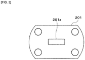
- FIG. 3 is a front view showing a mixing promoter 201 in FIG. 2
- the chamber 20 according to the present embodiment includes: a plurality of chamber bodies 200 aligned along the flow direction of the mixed gas 8; mixing promoters 201 each provided between the chamber bodies 200.
- Each chamber body 200 and each mixing promoter 201 are fastened to each other by fastening members 203 such as a bolt and a nut, for example.
- the chamber body 200 is a tubular body to which the gas sensors 1 and the air-fuel ratio meter 6 can be attached.
- the number of the chamber bodies 200 may be changed depending on the number of the gas sensors 1 and the air fuel ratio meter 6 used.
- the mixing promoters 201 are configured to promote the mixing of the first gas 3a and the second gas (the NO gas 5a, the air 5b, and the combustible gas 5c), and are provided in the pipe 2 (the chamber 20) on an upstream side of the gas sensor 1 in the flow direction of the first gas 3a (the mixed gas 8) and on a downstream side of the addition position of the second gas.
- each of the mixing promoters 201 is formed of a plate-shaped member having an opening 201a at substantially the center.
- the opening 201a according to the present embodiment has a rectangular shape extending so as to be long in the horizontal direction.
- the opening 201a may have other shapes such as a circle or a square, for example.
- the opening area of the opening 201a is narrower than an inner cross-sectional area of the chamber body 200. These areas are areas on a surface orthogonal to the flow direction of the mixed gas 8.
- each mixing promoter 201 according to the present embodiment is a member for reducing a flow path cross-sectional area in the pipe as compared with the upstream and the downstream of the mixing promoter 201 in the flow direction of the first gas 3a (the mixed gas 8).
- each mixing promoter 201 according to the present embodiment is a member for narrowing the flow path.
- each mixing promoter 201 is provided between the chamber bodies 200 so as to correspond to each gas sensor 1, the mixing promoter 201 may be provided only at an introduction port of the most upstream chamber body 200 (an opening through which the mixed gas 8 is introduced). Although it discloses each mixing promoter 201 as being a different member from the chamber body 200, it may be integral with the chamber body 200. Further, the mixing promoter 201 is not limited to the plate-shaped member provided with the opening, and it may be other forms such as a rod-shaped member arranged to hinder the flow of the mixed gas 8, and a protrusion provided on an inner peripheral surface of each chamber body 200.
- FIG. 4 is a flowchart showing a response time evaluation method for the gas sensors using the response time evaluation device shown in FIGS. 1 to 3 .
- the response time evaluation method for the gas sensor according to the present embodiment includes: an attachment step S1; a first gas supply start step S2; an addition step S3; and a time difference acquisition step S4.
- the gas sensors 1 are attached to the chamber 20 of the pipe 2.
- the first gas supply start step S2 the supplying of the first gas 3a to the pipe 2 is started by the first gas supplier 3.
- step S3 at least one of the first to third connecting pipes 51, 54, 57 is opened by at least one of the first to third connecting pipe on-off valves 52, 55, 58, and at least one of the NO gas 5a, the air 5b and the combustible gas 5c as the second gas is added to the first gas 3a in the pipe 2.
- the NO gas 5a is added.
- the response time of the oxygen output of the gas sensors 1 at least one of the air 5b and the combustible gas 5c is added.
- At least one of the first to third connecting pipes 51, 54, 57 by at least one of the first to third connecting pipe on-off valves 52, 55, 58 at least one of the first supply control valve 502 and the first supply pipe on-off valve 503, the second supply control valve 532 and the second supply pipe on-off valve 533, as well as the third supply control valve 562 and the third supply pipe on-off valve 563 is opened to form the flow of the NO gas in the first supply pipe 501, and/or to form the flow of the air 5b in the second supply pipe 531, and/or to form the flow of the combustible gas 5c in the third supply pipe 561.
- Such previous forming of the flow can allow at least one of the NO gas 5a, the air 5b and the combustible gas 5c to be immediately added as the second gas to the first gas 3a in the pipe 2 when at least one of the first to third connecting pipes 51, 54, 57 is opened by at least one of the first to third connecting pipe on-off valves 52, 55, 58.
- the corresponding first to third supply pipe on-off valve 503, 533, 563 is closed.
- a time difference is acquired between a time point when at least one of the first to third connecting pipes 51, 54, 57 is opened by at least one of the first to third connecting pipe on-off valves 52, 55, 58, and a time point when the gas sensors detect components in the mixed gas 8 of the first and the second gases. This time difference can be evaluated as the response time of the gas sensors 1.
- the second gas adding machine 5 includes: the second gas supply source 50, 53, 56; the connecting pipe 51, 54, 57 for connecting the supply source 50, 53, 56 to the pipe; and the connecting pipe on-off valve 52, 55, 58 for opening and closing the connecting pipe 51, 54, 57, so that the evaluation accuracy of response characteristic of the gas sensors 1 can be improved while simulating the actual use environment of the gas sensors 1.
- the connecting pipe on-off valve 52, 55, 58 is the electrically driven valve, so that the timing of opening/closing can be more accurately obtained and the evaluation accuracy of the response characteristic of the gas sensors 1 can be more reliably improved.
- the connecting pipe on-off valve 52, 55, 58 are the solenoid valve, so that the timing of opening/closing can be more accurately acquired and the evaluation accuracy of the response characteristic of the gas sensors 1 can be further reliably improved.
- the distance between the addition position of the second gas and the gas sensor 1 according to the present embodiment is shorter than the distance between the addition position of the second gas and the first gas supplier 3, so that a quicker effect of the addition of the second gas at the position of the gas sensors 1 can be more reliably produced.
- the addition position of the second gas according to the present embodiment is on the downstream side of the cooler 4 in the flow direction of the first gas 3a, so that the quicker effect of the addition of the second gas at the position of the gas sensors 1 can be more reliably produced.
- the connecting pipe 51, 54, 57 is closed by the connecting pipe on-off valve 52, 55, 58, it is configured to be capable of forming the flow of the second gas in the supply pipe 501, 531, 561, so that the second gas can be added immediately when the connecting pipe on-off valve 52, 55, 58 is opened, and the evaluation accuracy of the response characteristic of the gas sensors 1 can be more reliably improved.
- the supply source 50, 53, 56 is provided with the supply pipe on-off valve 503, 533, 563 disposed on the downstream side of the connection position of the connecting pipe 51, 54, 57 to the supply pipe 501, 531, 561 in the flow direction of the second gas, so that when the connecting pipe on-off valve 52, 55, 58 is opened, the supply pipe on-off valve 503, 533, 563 is closed, whereby the second gas can be more quickly supplied to the connecting pipe 51, 54, 57, and the evaluation accuracy of the response characteristic of the gas sensors 1 can be more reliably improved.
- the mixing promoters 201 for promoting the mixing of the first and second gases is provided on the upstream side of the gas sensors 1 in the flow direction of the first gas 3a and on the downstream side of the addition position of the second gas, so that it is possible to avoid occurrence of detection delay of the gas sensors 1 due to insufficient mixing of the first and second gases and to improve the evaluation accuracy of the response characteristic of the gas sensors 1 more reliably.
- each mixing promoter 201 is a member for reducing the flow path cross-sectional area in the pipe as compared with the upstream and downstream of the mixing promoter 201 in the flow direction of the first gas 3a, so that it is possible to generate a vortex in the mixed gas 8 of the first and the second gases and to promote the mixing of the first gas 3a and the second gas more reliably.
Landscapes
- Chemical & Material Sciences (AREA)
- Life Sciences & Earth Sciences (AREA)
- Engineering & Computer Science (AREA)
- Health & Medical Sciences (AREA)
- Analytical Chemistry (AREA)
- Food Science & Technology (AREA)
- Medicinal Chemistry (AREA)
- Physics & Mathematics (AREA)
- Combustion & Propulsion (AREA)
- Biochemistry (AREA)
- General Health & Medical Sciences (AREA)
- General Physics & Mathematics (AREA)
- Immunology (AREA)
- Pathology (AREA)
- Investigating Or Analyzing Materials By The Use Of Electric Means (AREA)
- Measuring Oxygen Concentration In Cells (AREA)
Applications Claiming Priority (1)
| Application Number | Priority Date | Filing Date | Title |
|---|---|---|---|
| JP2018048305A JP2019158758A (ja) | 2018-03-15 | 2018-03-15 | ガスセンサの応答時間評価装置及び方法 |
Publications (3)
| Publication Number | Publication Date |
|---|---|
| EP3540430A2 true EP3540430A2 (de) | 2019-09-18 |
| EP3540430A3 EP3540430A3 (de) | 2019-10-09 |
| EP3540430B1 EP3540430B1 (de) | 2020-09-09 |
Family
ID=65657324
Family Applications (1)
| Application Number | Title | Priority Date | Filing Date |
|---|---|---|---|
| EP19160195.4A Active EP3540430B1 (de) | 2018-03-15 | 2019-03-01 | Vorrichtung und verfahren zur auswertung der ansprechzeit eines gassensors |
Country Status (4)
| Country | Link |
|---|---|
| US (1) | US11016069B2 (de) |
| EP (1) | EP3540430B1 (de) |
| JP (1) | JP2019158758A (de) |
| CN (1) | CN110274989B (de) |
Families Citing this family (8)
| Publication number | Priority date | Publication date | Assignee | Title |
|---|---|---|---|---|
| JP6923473B2 (ja) * | 2018-03-23 | 2021-08-18 | 日本碍子株式会社 | ガスセンサの検査装置 |
| CN111044218A (zh) * | 2019-12-31 | 2020-04-21 | 中国科学院微电子研究所 | 真空压力计响应时间测量装置 |
| CN111044219A (zh) * | 2019-12-31 | 2020-04-21 | 中国科学院微电子研究所 | 真空压力计响应时间测量装置及方法 |
| JP7372864B2 (ja) * | 2020-03-27 | 2023-11-01 | 日本碍子株式会社 | ガスセンサの試験方法およびガスセンサの耐久試験用システム |
| CN113391023A (zh) * | 2021-07-12 | 2021-09-14 | 中国特种设备检测研究院 | 一种NOx排放测试平台 |
| CN114113480B (zh) * | 2021-11-23 | 2024-03-26 | 青岛崂应海纳光电环保集团有限公司 | 一种多气体传感器响应时间自动测试装置和方法 |
| CN114778613A (zh) * | 2022-04-15 | 2022-07-22 | 四川大学 | 一种用于mems气体传感器的评测系统 |
| CN114778773B (zh) * | 2022-04-21 | 2023-11-14 | 国网重庆市电力公司 | 一种储能系统的火灾极早期预警设备、控制系统及方法 |
Citations (2)
| Publication number | Priority date | Publication date | Assignee | Title |
|---|---|---|---|---|
| JP2011039041A (ja) | 2009-07-17 | 2011-02-24 | Ngk Insulators Ltd | アンモニア濃度検出センサ |
| JP2016090484A (ja) | 2014-11-07 | 2016-05-23 | 日本碍子株式会社 | 評価装置及び評価方法 |
Family Cites Families (18)
| Publication number | Priority date | Publication date | Assignee | Title |
|---|---|---|---|---|
| US3762878A (en) * | 1971-04-19 | 1973-10-02 | Beckman Instruments Inc | Apparatus for analyzing ambient air |
| JPS5295289A (en) * | 1976-02-05 | 1977-08-10 | Nissan Motor | Inspection method and apparatus for oxygen sensor |
| JPH0713600B2 (ja) * | 1986-12-29 | 1995-02-15 | 日本特殊陶業株式会社 | 酸素センサ評価装置 |
| US5565180A (en) * | 1987-03-02 | 1996-10-15 | Turbotak Inc. | Method of treating gases |
| JP2624531B2 (ja) * | 1988-11-14 | 1997-06-25 | 日本碍子株式会社 | センサ特性評価法 |
| JP2514701B2 (ja) * | 1988-12-02 | 1996-07-10 | 日本特殊陶業株式会社 | 酸素センサ |
| JPH0670619B2 (ja) * | 1989-07-01 | 1994-09-07 | 日本碍子株式会社 | 空燃比センサ評価法および装置 |
| JP2000252269A (ja) * | 1992-09-21 | 2000-09-14 | Mitsubishi Electric Corp | 液体気化装置及び液体気化方法 |
| DE59409834D1 (de) * | 1993-04-17 | 2001-09-27 | Messer Griesheim Austria Ges M | Gerät zur kontrollierten Zudosierung von NO zur Atemluft von Patienten |
| DE10244125B4 (de) * | 2002-09-23 | 2008-01-31 | Siemens Ag | Verfahren zur Bewertung des Zeitverhaltens eines NOx-Sensors |
| US7722749B2 (en) * | 2005-09-01 | 2010-05-25 | Delphi Technologies, Inc. | Gas sensor and method for forming same |
| JP5008086B2 (ja) * | 2008-05-23 | 2012-08-22 | 独立行政法人産業技術総合研究所 | 調圧機能付高速ガス切替装置 |
| JP5126388B2 (ja) * | 2010-08-19 | 2013-01-23 | 株式会社デンソー | ガスセンサ制御装置 |
| JP4934754B1 (ja) | 2011-10-18 | 2012-05-16 | 株式会社ベスト測器 | 模擬ガス供給装置 |
| CN103454383A (zh) * | 2013-09-05 | 2013-12-18 | 长三角(嘉兴)纳米科技产业发展研究院 | 一种气体传感器动态响应性能测试系统 |
| KR101621829B1 (ko) * | 2014-06-25 | 2016-05-17 | 강림중공업 주식회사 | 기화된 가연성 기체의 연소장치 및 이를 구비한 연소시스템 |
| JP6561587B2 (ja) * | 2015-05-29 | 2019-08-21 | 富士電機株式会社 | 分析装置および排ガス処理システム |
| JP6571037B2 (ja) * | 2016-03-31 | 2019-09-04 | 日本碍子株式会社 | ガスセンサの検査装置 |
-
2018
- 2018-03-15 JP JP2018048305A patent/JP2019158758A/ja active Pending
-
2019
- 2019-03-01 EP EP19160195.4A patent/EP3540430B1/de active Active
- 2019-03-01 CN CN201910154457.0A patent/CN110274989B/zh active Active
- 2019-03-13 US US16/351,556 patent/US11016069B2/en active Active
Patent Citations (2)
| Publication number | Priority date | Publication date | Assignee | Title |
|---|---|---|---|---|
| JP2011039041A (ja) | 2009-07-17 | 2011-02-24 | Ngk Insulators Ltd | アンモニア濃度検出センサ |
| JP2016090484A (ja) | 2014-11-07 | 2016-05-23 | 日本碍子株式会社 | 評価装置及び評価方法 |
Also Published As
| Publication number | Publication date |
|---|---|
| JP2019158758A (ja) | 2019-09-19 |
| CN110274989B (zh) | 2023-04-07 |
| EP3540430A3 (de) | 2019-10-09 |
| CN110274989A (zh) | 2019-09-24 |
| US11016069B2 (en) | 2021-05-25 |
| EP3540430B1 (de) | 2020-09-09 |
| US20190285597A1 (en) | 2019-09-19 |
Similar Documents
| Publication | Publication Date | Title |
|---|---|---|
| EP3540430B1 (de) | Vorrichtung und verfahren zur auswertung der ansprechzeit eines gassensors | |
| US9970372B2 (en) | Method of diagnosing an exhaust gas sensor | |
| CN100526872C (zh) | 汽车用氧传感器性能测试装置 | |
| US20090139210A1 (en) | Gas concentration sensor drift and failure detection system | |
| EP2581583B1 (de) | Verfahren zum Betrieb einer Gasturbine und Gasturbine | |
| RU2717865C2 (ru) | Система и способ (варианты) эксплуатации лазерного датчика давления | |
| CN100449130C (zh) | 用于诊断λ-探头的动态特性的方法和装置 | |
| EP3075996B1 (de) | Kraftstoffeigenschaftsschätzungsvorrichtung | |
| CN101139955B (zh) | 利用离子信号对燃料和空气属性的改变进行补偿 | |
| Azeem et al. | Comparative analysis of different methodologies to calculate lambda (λ) based on extensive and systemic experimentation on a hydrogen internal combustion engine | |
| US20110082622A1 (en) | Method and device for diagnosing the dynamics of an exhaust gas sensor | |
| US7428838B2 (en) | Calibration for an oil-consumption-measurement system | |
| US4825683A (en) | Apparatus for evaluating an oxygen sensor | |
| US9791350B2 (en) | Exhaust gas analyzer verification system | |
| CN106093298B (zh) | 一种火药燃烧气体成分测试方法 | |
| US8069709B2 (en) | Ion-based triple sensor | |
| JP5395318B2 (ja) | 内燃機関の運転方法および装置 | |
| KR20230002114A (ko) | 플레어 가스의 직접 연소식 열량 측정 시스템 | |
| Hegarty et al. | Fast O 2 measurement using modified uego sensors in the intake and exhaust of a diesel engine | |
| KR20170037511A (ko) | 차재 엔진의 연료 유량 검지 방법 | |
| Bergmann et al. | Using ejector diluters to sample vehicle exhaust at elevated pressures and temperatures | |
| Fonseca et al. | New methodologies to measure in real time fuel consumption of internal combustion engines | |
| Grados et al. | Correcting injection pressure maladjustments to reduce NOX emissions by marine diesel engines | |
| CA2493529A1 (en) | Method and device for controlling the functioning of a nitrogen oxide trap for an internal combustion engine running on a lean mixture | |
| GB2546095A (en) | System for simulating an aftertreatment of an engine |
Legal Events
| Date | Code | Title | Description |
|---|---|---|---|
| PUAI | Public reference made under article 153(3) epc to a published international application that has entered the european phase |
Free format text: ORIGINAL CODE: 0009012 |
|
| STAA | Information on the status of an ep patent application or granted ep patent |
Free format text: STATUS: THE APPLICATION HAS BEEN PUBLISHED |
|
| PUAL | Search report despatched |
Free format text: ORIGINAL CODE: 0009013 |
|
| AK | Designated contracting states |
Kind code of ref document: A2 Designated state(s): AL AT BE BG CH CY CZ DE DK EE ES FI FR GB GR HR HU IE IS IT LI LT LU LV MC MK MT NL NO PL PT RO RS SE SI SK SM TR |
|
| AX | Request for extension of the european patent |
Extension state: BA ME |
|
| AK | Designated contracting states |
Kind code of ref document: A3 Designated state(s): AL AT BE BG CH CY CZ DE DK EE ES FI FR GB GR HR HU IE IS IT LI LT LU LV MC MK MT NL NO PL PT RO RS SE SI SK SM TR |
|
| AX | Request for extension of the european patent |
Extension state: BA ME |
|
| RIC1 | Information provided on ipc code assigned before grant |
Ipc: G01N 33/00 20060101AFI20190902BHEP |
|
| STAA | Information on the status of an ep patent application or granted ep patent |
Free format text: STATUS: REQUEST FOR EXAMINATION WAS MADE |
|
| GRAP | Despatch of communication of intention to grant a patent |
Free format text: ORIGINAL CODE: EPIDOSNIGR1 |
|
| STAA | Information on the status of an ep patent application or granted ep patent |
Free format text: STATUS: GRANT OF PATENT IS INTENDED |
|
| 17P | Request for examination filed |
Effective date: 20200319 |
|
| RBV | Designated contracting states (corrected) |
Designated state(s): AL AT BE BG CH CY CZ DE DK EE ES FI FR GB GR HR HU IE IS IT LI LT LU LV MC MK MT NL NO PL PT RO RS SE SI SK SM TR |
|
| INTG | Intention to grant announced |
Effective date: 20200417 |
|
| RIN1 | Information on inventor provided before grant (corrected) |
Inventor name: SEIMORI, TOMOYA |
|
| GRAS | Grant fee paid |
Free format text: ORIGINAL CODE: EPIDOSNIGR3 |
|
| GRAA | (expected) grant |
Free format text: ORIGINAL CODE: 0009210 |
|
| STAA | Information on the status of an ep patent application or granted ep patent |
Free format text: STATUS: THE PATENT HAS BEEN GRANTED |
|
| AK | Designated contracting states |
Kind code of ref document: B1 Designated state(s): AL AT BE BG CH CY CZ DE DK EE ES FI FR GB GR HR HU IE IS IT LI LT LU LV MC MK MT NL NO PL PT RO RS SE SI SK SM TR |
|
| REG | Reference to a national code |
Ref country code: GB Ref legal event code: FG4D |
|
| REG | Reference to a national code |
Ref country code: AT Ref legal event code: REF Ref document number: 1312213 Country of ref document: AT Kind code of ref document: T Effective date: 20200915 Ref country code: CH Ref legal event code: EP |
|
| REG | Reference to a national code |
Ref country code: DE Ref legal event code: R096 Ref document number: 602019000587 Country of ref document: DE |
|
| REG | Reference to a national code |
Ref country code: IE Ref legal event code: FG4D |
|
| REG | Reference to a national code |
Ref country code: LT Ref legal event code: MG4D |
|
| PG25 | Lapsed in a contracting state [announced via postgrant information from national office to epo] |
Ref country code: GR Free format text: LAPSE BECAUSE OF FAILURE TO SUBMIT A TRANSLATION OF THE DESCRIPTION OR TO PAY THE FEE WITHIN THE PRESCRIBED TIME-LIMIT Effective date: 20201210 Ref country code: LT Free format text: LAPSE BECAUSE OF FAILURE TO SUBMIT A TRANSLATION OF THE DESCRIPTION OR TO PAY THE FEE WITHIN THE PRESCRIBED TIME-LIMIT Effective date: 20200909 Ref country code: FI Free format text: LAPSE BECAUSE OF FAILURE TO SUBMIT A TRANSLATION OF THE DESCRIPTION OR TO PAY THE FEE WITHIN THE PRESCRIBED TIME-LIMIT Effective date: 20200909 Ref country code: SE Free format text: LAPSE BECAUSE OF FAILURE TO SUBMIT A TRANSLATION OF THE DESCRIPTION OR TO PAY THE FEE WITHIN THE PRESCRIBED TIME-LIMIT Effective date: 20200909 Ref country code: HR Free format text: LAPSE BECAUSE OF FAILURE TO SUBMIT A TRANSLATION OF THE DESCRIPTION OR TO PAY THE FEE WITHIN THE PRESCRIBED TIME-LIMIT Effective date: 20200909 Ref country code: BG Free format text: LAPSE BECAUSE OF FAILURE TO SUBMIT A TRANSLATION OF THE DESCRIPTION OR TO PAY THE FEE WITHIN THE PRESCRIBED TIME-LIMIT Effective date: 20201209 Ref country code: NO Free format text: LAPSE BECAUSE OF FAILURE TO SUBMIT A TRANSLATION OF THE DESCRIPTION OR TO PAY THE FEE WITHIN THE PRESCRIBED TIME-LIMIT Effective date: 20201209 |
|
| REG | Reference to a national code |
Ref country code: AT Ref legal event code: MK05 Ref document number: 1312213 Country of ref document: AT Kind code of ref document: T Effective date: 20200909 |
|
| REG | Reference to a national code |
Ref country code: NL Ref legal event code: MP Effective date: 20200909 |
|
| PG25 | Lapsed in a contracting state [announced via postgrant information from national office to epo] |
Ref country code: PL Free format text: LAPSE BECAUSE OF FAILURE TO SUBMIT A TRANSLATION OF THE DESCRIPTION OR TO PAY THE FEE WITHIN THE PRESCRIBED TIME-LIMIT Effective date: 20200909 Ref country code: RS Free format text: LAPSE BECAUSE OF FAILURE TO SUBMIT A TRANSLATION OF THE DESCRIPTION OR TO PAY THE FEE WITHIN THE PRESCRIBED TIME-LIMIT Effective date: 20200909 Ref country code: LV Free format text: LAPSE BECAUSE OF FAILURE TO SUBMIT A TRANSLATION OF THE DESCRIPTION OR TO PAY THE FEE WITHIN THE PRESCRIBED TIME-LIMIT Effective date: 20200909 |
|
| PG25 | Lapsed in a contracting state [announced via postgrant information from national office to epo] |
Ref country code: EE Free format text: LAPSE BECAUSE OF FAILURE TO SUBMIT A TRANSLATION OF THE DESCRIPTION OR TO PAY THE FEE WITHIN THE PRESCRIBED TIME-LIMIT Effective date: 20200909 Ref country code: PT Free format text: LAPSE BECAUSE OF FAILURE TO SUBMIT A TRANSLATION OF THE DESCRIPTION OR TO PAY THE FEE WITHIN THE PRESCRIBED TIME-LIMIT Effective date: 20210111 Ref country code: RO Free format text: LAPSE BECAUSE OF FAILURE TO SUBMIT A TRANSLATION OF THE DESCRIPTION OR TO PAY THE FEE WITHIN THE PRESCRIBED TIME-LIMIT Effective date: 20200909 Ref country code: CZ Free format text: LAPSE BECAUSE OF FAILURE TO SUBMIT A TRANSLATION OF THE DESCRIPTION OR TO PAY THE FEE WITHIN THE PRESCRIBED TIME-LIMIT Effective date: 20200909 Ref country code: SM Free format text: LAPSE BECAUSE OF FAILURE TO SUBMIT A TRANSLATION OF THE DESCRIPTION OR TO PAY THE FEE WITHIN THE PRESCRIBED TIME-LIMIT Effective date: 20200909 |
|
| PG25 | Lapsed in a contracting state [announced via postgrant information from national office to epo] |
Ref country code: IS Free format text: LAPSE BECAUSE OF FAILURE TO SUBMIT A TRANSLATION OF THE DESCRIPTION OR TO PAY THE FEE WITHIN THE PRESCRIBED TIME-LIMIT Effective date: 20210109 Ref country code: ES Free format text: LAPSE BECAUSE OF FAILURE TO SUBMIT A TRANSLATION OF THE DESCRIPTION OR TO PAY THE FEE WITHIN THE PRESCRIBED TIME-LIMIT Effective date: 20200909 Ref country code: AT Free format text: LAPSE BECAUSE OF FAILURE TO SUBMIT A TRANSLATION OF THE DESCRIPTION OR TO PAY THE FEE WITHIN THE PRESCRIBED TIME-LIMIT Effective date: 20200909 Ref country code: AL Free format text: LAPSE BECAUSE OF FAILURE TO SUBMIT A TRANSLATION OF THE DESCRIPTION OR TO PAY THE FEE WITHIN THE PRESCRIBED TIME-LIMIT Effective date: 20200909 |
|
| REG | Reference to a national code |
Ref country code: DE Ref legal event code: R097 Ref document number: 602019000587 Country of ref document: DE |
|
| PG25 | Lapsed in a contracting state [announced via postgrant information from national office to epo] |
Ref country code: SK Free format text: LAPSE BECAUSE OF FAILURE TO SUBMIT A TRANSLATION OF THE DESCRIPTION OR TO PAY THE FEE WITHIN THE PRESCRIBED TIME-LIMIT Effective date: 20200909 |
|
| PLBE | No opposition filed within time limit |
Free format text: ORIGINAL CODE: 0009261 |
|
| STAA | Information on the status of an ep patent application or granted ep patent |
Free format text: STATUS: NO OPPOSITION FILED WITHIN TIME LIMIT |
|
| 26N | No opposition filed |
Effective date: 20210610 |
|
| PG25 | Lapsed in a contracting state [announced via postgrant information from national office to epo] |
Ref country code: SI Free format text: LAPSE BECAUSE OF FAILURE TO SUBMIT A TRANSLATION OF THE DESCRIPTION OR TO PAY THE FEE WITHIN THE PRESCRIBED TIME-LIMIT Effective date: 20200909 Ref country code: DK Free format text: LAPSE BECAUSE OF FAILURE TO SUBMIT A TRANSLATION OF THE DESCRIPTION OR TO PAY THE FEE WITHIN THE PRESCRIBED TIME-LIMIT Effective date: 20200909 |
|
| PG25 | Lapsed in a contracting state [announced via postgrant information from national office to epo] |
Ref country code: MC Free format text: LAPSE BECAUSE OF FAILURE TO SUBMIT A TRANSLATION OF THE DESCRIPTION OR TO PAY THE FEE WITHIN THE PRESCRIBED TIME-LIMIT Effective date: 20200909 Ref country code: IT Free format text: LAPSE BECAUSE OF FAILURE TO SUBMIT A TRANSLATION OF THE DESCRIPTION OR TO PAY THE FEE WITHIN THE PRESCRIBED TIME-LIMIT Effective date: 20200909 |
|
| REG | Reference to a national code |
Ref country code: BE Ref legal event code: MM Effective date: 20210331 |
|
| PG25 | Lapsed in a contracting state [announced via postgrant information from national office to epo] |
Ref country code: FR Free format text: LAPSE BECAUSE OF NON-PAYMENT OF DUE FEES Effective date: 20210331 Ref country code: IE Free format text: LAPSE BECAUSE OF NON-PAYMENT OF DUE FEES Effective date: 20210301 Ref country code: LU Free format text: LAPSE BECAUSE OF NON-PAYMENT OF DUE FEES Effective date: 20210301 |
|
| PG25 | Lapsed in a contracting state [announced via postgrant information from national office to epo] |
Ref country code: BE Free format text: LAPSE BECAUSE OF NON-PAYMENT OF DUE FEES Effective date: 20210331 |
|
| REG | Reference to a national code |
Ref country code: CH Ref legal event code: PL |
|
| PG25 | Lapsed in a contracting state [announced via postgrant information from national office to epo] |
Ref country code: LI Free format text: LAPSE BECAUSE OF NON-PAYMENT OF DUE FEES Effective date: 20220331 Ref country code: CH Free format text: LAPSE BECAUSE OF NON-PAYMENT OF DUE FEES Effective date: 20220331 |
|
| PG25 | Lapsed in a contracting state [announced via postgrant information from national office to epo] |
Ref country code: NL Free format text: LAPSE BECAUSE OF NON-PAYMENT OF DUE FEES Effective date: 20200923 Ref country code: CY Free format text: LAPSE BECAUSE OF FAILURE TO SUBMIT A TRANSLATION OF THE DESCRIPTION OR TO PAY THE FEE WITHIN THE PRESCRIBED TIME-LIMIT Effective date: 20200909 |
|
| PG25 | Lapsed in a contracting state [announced via postgrant information from national office to epo] |
Ref country code: HU Free format text: LAPSE BECAUSE OF FAILURE TO SUBMIT A TRANSLATION OF THE DESCRIPTION OR TO PAY THE FEE WITHIN THE PRESCRIBED TIME-LIMIT; INVALID AB INITIO Effective date: 20190301 |
|
| GBPC | Gb: european patent ceased through non-payment of renewal fee |
Effective date: 20230301 |
|
| PG25 | Lapsed in a contracting state [announced via postgrant information from national office to epo] |
Ref country code: GB Free format text: LAPSE BECAUSE OF NON-PAYMENT OF DUE FEES Effective date: 20230301 |
|
| PG25 | Lapsed in a contracting state [announced via postgrant information from national office to epo] |
Ref country code: GB Free format text: LAPSE BECAUSE OF NON-PAYMENT OF DUE FEES Effective date: 20230301 |
|
| PG25 | Lapsed in a contracting state [announced via postgrant information from national office to epo] |
Ref country code: MK Free format text: LAPSE BECAUSE OF FAILURE TO SUBMIT A TRANSLATION OF THE DESCRIPTION OR TO PAY THE FEE WITHIN THE PRESCRIBED TIME-LIMIT Effective date: 20200909 |
|
| PG25 | Lapsed in a contracting state [announced via postgrant information from national office to epo] |
Ref country code: MT Free format text: LAPSE BECAUSE OF FAILURE TO SUBMIT A TRANSLATION OF THE DESCRIPTION OR TO PAY THE FEE WITHIN THE PRESCRIBED TIME-LIMIT Effective date: 20200909 |
|
| PGFP | Annual fee paid to national office [announced via postgrant information from national office to epo] |
Ref country code: DE Payment date: 20250128 Year of fee payment: 7 |
|
| PG25 | Lapsed in a contracting state [announced via postgrant information from national office to epo] |
Ref country code: TR Free format text: LAPSE BECAUSE OF FAILURE TO SUBMIT A TRANSLATION OF THE DESCRIPTION OR TO PAY THE FEE WITHIN THE PRESCRIBED TIME-LIMIT Effective date: 20200909 |