EP3540431A2 - Dispositif de mesure et procédé de mesure permettant de déterminer un ingrédient ou un paramètre de qualité de l'eau ou des eaux usées - Google Patents
Dispositif de mesure et procédé de mesure permettant de déterminer un ingrédient ou un paramètre de qualité de l'eau ou des eaux usées Download PDFInfo
- Publication number
- EP3540431A2 EP3540431A2 EP19162102.8A EP19162102A EP3540431A2 EP 3540431 A2 EP3540431 A2 EP 3540431A2 EP 19162102 A EP19162102 A EP 19162102A EP 3540431 A2 EP3540431 A2 EP 3540431A2
- Authority
- EP
- European Patent Office
- Prior art keywords
- sample
- temperature
- heating
- reaction
- carrier gas
- Prior art date
- Legal status (The legal status is an assumption and is not a legal conclusion. Google has not performed a legal analysis and makes no representation as to the accuracy of the status listed.)
- Granted
Links
Images

Classifications
-
- G—PHYSICS
- G01—MEASURING; TESTING
- G01N—INVESTIGATING OR ANALYSING MATERIALS BY DETERMINING THEIR CHEMICAL OR PHYSICAL PROPERTIES
- G01N1/00—Sampling; Preparing specimens for investigation
- G01N1/28—Preparing specimens for investigation including physical details of (bio-)chemical methods covered elsewhere, e.g. G01N33/50, C12Q
- G01N1/44—Sample treatment involving radiation, e.g. heat
-
- G—PHYSICS
- G01—MEASURING; TESTING
- G01K—MEASURING TEMPERATURE; MEASURING QUANTITY OF HEAT; THERMALLY-SENSITIVE ELEMENTS NOT OTHERWISE PROVIDED FOR
- G01K1/00—Details of thermometers not specially adapted for particular types of thermometer
- G01K1/14—Supports; Fastening devices; Arrangements for mounting thermometers in particular locations
-
- G—PHYSICS
- G01—MEASURING; TESTING
- G01N—INVESTIGATING OR ANALYSING MATERIALS BY DETERMINING THEIR CHEMICAL OR PHYSICAL PROPERTIES
- G01N1/00—Sampling; Preparing specimens for investigation
- G01N1/02—Devices for withdrawing samples
- G01N1/10—Devices for withdrawing samples in the liquid or fluent state
- G01N1/14—Suction devices, e.g. pumps; Ejector devices
-
- G—PHYSICS
- G01—MEASURING; TESTING
- G01N—INVESTIGATING OR ANALYSING MATERIALS BY DETERMINING THEIR CHEMICAL OR PHYSICAL PROPERTIES
- G01N21/00—Investigating or analysing materials by the use of optical means, i.e. using sub-millimetre waves, infrared, visible or ultraviolet light
- G01N21/62—Systems in which the material investigated is excited whereby it emits light or causes a change in wavelength of the incident light
- G01N21/71—Systems in which the material investigated is excited whereby it emits light or causes a change in wavelength of the incident light thermally excited
- G01N21/72—Systems in which the material investigated is excited whereby it emits light or causes a change in wavelength of the incident light thermally excited using flame burners
-
- G—PHYSICS
- G01—MEASURING; TESTING
- G01N—INVESTIGATING OR ANALYSING MATERIALS BY DETERMINING THEIR CHEMICAL OR PHYSICAL PROPERTIES
- G01N31/00—Investigating or analysing non-biological materials by the use of the chemical methods specified in the subgroup; Apparatus specially adapted for such methods
- G01N31/12—Investigating or analysing non-biological materials by the use of the chemical methods specified in the subgroup; Apparatus specially adapted for such methods using combustion
-
- G—PHYSICS
- G01—MEASURING; TESTING
- G01N—INVESTIGATING OR ANALYSING MATERIALS BY DETERMINING THEIR CHEMICAL OR PHYSICAL PROPERTIES
- G01N33/00—Investigating or analysing materials by specific methods not covered by groups G01N1/00 - G01N31/00
- G01N33/18—Water
- G01N33/1806—Biological oxygen demand [BOD] or chemical oxygen demand [COD]
-
- G—PHYSICS
- G01—MEASURING; TESTING
- G01N—INVESTIGATING OR ANALYSING MATERIALS BY DETERMINING THEIR CHEMICAL OR PHYSICAL PROPERTIES
- G01N33/00—Investigating or analysing materials by specific methods not covered by groups G01N1/00 - G01N31/00
- G01N33/18—Water
- G01N33/1826—Organic contamination in water
-
- G—PHYSICS
- G01—MEASURING; TESTING
- G01N—INVESTIGATING OR ANALYSING MATERIALS BY DETERMINING THEIR CHEMICAL OR PHYSICAL PROPERTIES
- G01N33/00—Investigating or analysing materials by specific methods not covered by groups G01N1/00 - G01N31/00
- G01N33/18—Water
- G01N33/1826—Organic contamination in water
- G01N33/1846—Total carbon analysis
-
- G—PHYSICS
- G01—MEASURING; TESTING
- G01N—INVESTIGATING OR ANALYSING MATERIALS BY DETERMINING THEIR CHEMICAL OR PHYSICAL PROPERTIES
- G01N1/00—Sampling; Preparing specimens for investigation
- G01N1/02—Devices for withdrawing samples
- G01N1/10—Devices for withdrawing samples in the liquid or fluent state
- G01N1/14—Suction devices, e.g. pumps; Ejector devices
- G01N2001/1445—Overpressure, pressurisation at sampling point
- G01N2001/1463—Injector; Air-lift
-
- G—PHYSICS
- G01—MEASURING; TESTING
- G01N—INVESTIGATING OR ANALYSING MATERIALS BY DETERMINING THEIR CHEMICAL OR PHYSICAL PROPERTIES
- G01N21/00—Investigating or analysing materials by the use of optical means, i.e. using sub-millimetre waves, infrared, visible or ultraviolet light
- G01N21/62—Systems in which the material investigated is excited whereby it emits light or causes a change in wavelength of the incident light
- G01N21/71—Systems in which the material investigated is excited whereby it emits light or causes a change in wavelength of the incident light thermally excited
- G01N21/72—Systems in which the material investigated is excited whereby it emits light or causes a change in wavelength of the incident light thermally excited using flame burners
- G01N2021/725—Systems in which the material investigated is excited whereby it emits light or causes a change in wavelength of the incident light thermally excited using flame burners for determining of metalloids, using Beilstein type reaction
-
- G—PHYSICS
- G01—MEASURING; TESTING
- G01N—INVESTIGATING OR ANALYSING MATERIALS BY DETERMINING THEIR CHEMICAL OR PHYSICAL PROPERTIES
- G01N21/00—Investigating or analysing materials by the use of optical means, i.e. using sub-millimetre waves, infrared, visible or ultraviolet light
- G01N21/17—Systems in which incident light is modified in accordance with the properties of the material investigated
- G01N21/25—Colour; Spectral properties, i.e. comparison of effect of material on the light at two or more different wavelengths or wavelength bands
- G01N21/31—Investigating relative effect of material at wavelengths characteristic of specific elements or molecules, e.g. atomic absorption spectrometry
- G01N21/35—Investigating relative effect of material at wavelengths characteristic of specific elements or molecules, e.g. atomic absorption spectrometry using infrared light
- G01N21/3504—Investigating relative effect of material at wavelengths characteristic of specific elements or molecules, e.g. atomic absorption spectrometry using infrared light for analysing gases, e.g. multi-gas analysis
-
- G—PHYSICS
- G01—MEASURING; TESTING
- G01N—INVESTIGATING OR ANALYSING MATERIALS BY DETERMINING THEIR CHEMICAL OR PHYSICAL PROPERTIES
- G01N33/00—Investigating or analysing materials by specific methods not covered by groups G01N1/00 - G01N31/00
- G01N33/0004—Gaseous mixtures, e.g. polluted air
- G01N33/0009—General constructional details of gas analysers, e.g. portable test equipment
- G01N33/0027—General constructional details of gas analysers, e.g. portable test equipment concerning the detector
- G01N33/0036—General constructional details of gas analysers, e.g. portable test equipment concerning the detector specially adapted to detect a particular component
Definitions
- the invention relates to a measuring arrangement and / or a measuring method for determining an ingredient or quality parameter of water or wastewater.
- infrared detectors for the carbon content special chemiluminescence detectors respectively electrochemical sensors for the nitrogen content and so-called coulometric detectors for the halide content have been proven (among others).
- TOC total organic carbon
- a small amount of water is usually supplied with the transport gas heated to a predetermined temperature with a heater furnace where it evaporates and burns almost abruptly, and the combustion gas is fed to a NDIR-CO 2 detector whose CO 2 content indicator is a measure of forms the C content of the water sample.
- An advanced version of this process and a corresponding apparatus are in DE 43 44 441 C2 described.
- a modified arrangement for measuring very low TOC values - for example in ultrapure water or high purity solutions for medical applications - is in EP 0 684 471 A2 described.
- the US 5702954 describes a multi-stage digestion process for vegetable or animal phosphorus-containing samples of the phosphate content, which includes combustion in the presence of a reducing agent (such as hydrogen) and subsequent reaction with ozone in another reaction chamber at ambient temperature.
- a reducing agent such as hydrogen
- the US 2003/0032194 A1 describes a multi-stage oxidation process which was developed primarily for the determination of nitrogen and sulfur but also of phosphorus in a sample containing these elements.
- Thermal digestion processes using special catalysts or ozone are also from the JP 59154358 A or JP 61140863 A known.
- the invention is based on the object to provide an improved measuring arrangement and an improved measuring method, which can be used for various water ingredients or quality parameters, allow a cost-effective digestion of the samples and are easy and safe to handle in practice.
- the invention includes the idea of reducing the heat losses at the reaction module of the measuring arrangement by suitable design and control measures and in particular limiting housing temperatures of the reaction module in its head and foot areas which are critical during operating procedures. At the same time, the maximum temperature required in the reaction zone for efficient sample digestion should be ensured.
- the proposed reaction module and its operating method is characterized in that the reaction module, the resistance or infrared heater and means for sample and carrier gas supply are designed such that during operation of the measuring arrangement, an outer-head temperature T H ⁇ 80 ° C and an outer -Fußtemperatur T F ⁇ 150 ° C at a maximum temperature in the reaction zone T MAX ⁇ 1150 ° C.
- the reaction module, the resistance or infrared heater and means for sample and carrier gas supply are designed such that during operation of the measuring arrangement, a head temperature T H ⁇ 70 ° C and a foot temperature T F ⁇ 150 ° C, in particular ⁇ 120 ° C, wherein in particular the maximum temperature in the reaction zone T MAX ⁇ 1200 ° C.
- the proposed reaction module and operating method can be used in a modular manner in various measuring arrangements, which are designed inter alia for the determination of nitrogen and / or phosphorus and / or the content of organic carbon, TOC, or the chemical oxygen demand, COD.
- the reaction module has a two- or multi-layered thermal insulation which comprises a macroporous layer and a microporous layer.
- one of the layers of thermal insulation is formed by prefabricated annularlvessutz- / Keramikmaschineisoliermodule, which are known for example under the trade name Fibrothal® and commercially available.
- the reaction module is filled for the most part with a filling of porous ceramic balls.
- suitable ceramic spheres with size and porosity matched to the application, it is possible to optimize the flow or residence time of the sample in the reaction zone and, if appropriate, especially the residence time in different temperature ranges of the reaction zone and thus overall the T-mode of the reaction module .
- Al2O3 balls are used, which have especially average diameters of 6, 4.5, 2.7 and 1.2 mm, wherein at least two, preferably four layers of balls with different diameters are superimposed and the thickness of the individual layers in the In view of the specific application and process conditions are chosen such that the oxidation of the water constituents is reliably ensured to the analytes in the sample gas in the different temperature zones of the reactor.
- reaction module is an at least over the length of the reaction zone extending inner wall (or a separate reaction vessel) made of Al2O3 and in the head and foot each with a CFC insert with a Teflon sheath Having exhibiting O-ring as a sealing element.
- Aluminum oxide as a reactor material has sufficient temperature resistance and thermal conductivity for the operating conditions and, moreover, sufficient thermal shock resistance for practical operation. With a possible reduction in the digestion temperature, a high-performance stainless steel can also be used.
- the furnace head consists in particular of a mechanically reinforced fluorohydrocarbon for heat insulation.
- the oven base is application-related either of a mechanically reinforced fluorocarbon, or of a glass base with ceramic baffle plate for heat diversion of the hot reaction gas.
- the head section of the reaction module has an injection port for temporary insertion of an injection needle or for permanent retention of a supply tube, which in particular comprises an O-ring sprung inwardly by a silicone insert or inserted spring.
- the measuring arrangement specifically comprises a syringe operated by a compression spring or a stepper motor for introducing the sample into the reaction module.
- This type of charging of the reaction module with a sample is known as such, in particular from earlier patent applications / applications of the Applicant.
- the compression spring or the stepping motor is associated with a detector for detecting the beginning of an injection process of the sample in the reaction module. This idea of detection of the injection process, in conjunction with the use of the detection signal described below, is new.
- An alternative embodiment of the reaction module has a three-way valve connected to the supply tube for selectively introducing sample or a rinsing liquid into the reaction module.
- a detector for detecting the beginning of an injection process of the sample in the reaction module is preferably associated with the element supplying the sample feed, ie the three-way valve.
- adjusting means for adjusting the position of the end of the injection needle or of the supply tube in the reaction module are provided on the injection port.
- the resistance or infrared heater comprises a plurality of vertically ranked, separately controlled heating elements, in particular separate resistance heating / Keramikisoliermodulen.
- at least one of the heating elements is assigned a temperature sensor and a corresponding control input of a heating control device and the heating control device is designed such that the heating elements, in particular individually, can be acted upon by heating current in response to an output signal of the temperature sensor and according to a predetermined temperature profile of the reaction module.
- a resistance or infrared heating control means has a detector input for receiving an injection input signal representing a current entry operation of a sample, and the heating control means is arranged to vary the heating power of the resistance or infrared heating based on the injection input signal ,
- This measure can be particularly advantageously combined with the aforementioned measure of a temperature sensor control of the resistance or infrared heater, so as to account for the influence of the sample injection process on the temperature distribution in the reaction module differentiated.
- a PID control algorithm is advantageously implemented in the heating control device, which uses at least the output signal of a temperature sensor and optionally the injection input signal for temperature control in the reaction module.
- control of the measuring arrangement can be designed such that the means for sample and carrier gas supply have a feed control device for automatically controlled sample and carrier gas supply, in particular at least one input terminal for receiving an input signal supplied by the heating control device for influencing the automated sample and carrier gas supply.
- the sample injection is controlled in consideration of the current temperature conditions in the reaction module and possibly. Vary to a standard regime.
- heating elements of the resistance or infrared heater are assigned at least one temperature sensor and the signals of the or each temperature sensor are supplied to corresponding control inputs of the heating control device and the heating control device is operated such that the heating elements in response to an output signal of the associated temperature sensor and be acted upon in accordance with a predetermined temperature profile of the reaction module with heating current.
- a PID control algorithm is advantageously operated in the heating control device in such a way that it uses at least the output signal of a temperature sensor and optionally the injection input signal for temperature regulation in the reaction module.
- the means for sample and carrier gas supply have a feed control device for automatically controlled sample and carrier gas supply and are operated in such a way that fluctuations in the temperature in the reaction zone are minimized.
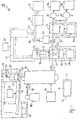
- Fig. 1 shows in the form of a schematic diagram of the overall structure of an exemplary measuring arrangement 10 for the determination of various water constituents of waste water or process water.
- the main component of the arrangement 10 is a reaction module 11 described below; but it can also be used in its place another type of combustion furnace (such as with radiant heating).
- a reaction module 11 described below; but it can also be used in its place another type of combustion furnace (such as with radiant heating).
- combustion furnace such as with radiant heating
- a symbolically represented control unit (controller) 12 controls the overall process of the sample digestion and the measuring operations and, for this purpose, is of course connected to the essential shut-off, transport, heating and detection devices of the arrangement. Implementation, connection and operation of such a control device are, on the basis of the method description given below and the device structure explained below, in the context of expert action.
- the reaction module 11 is the input side, a carrier gas storage 14 for the provision of carrier gas for the measuring operations associated with associated input valve means 15. Further, the furnace has a heater control unit 17 for controlling the electric furnace heater and a sample feeder 18 for sample introduction into a sample injection valve 19 of the furnace.
- the sample supply device 18 comprises a sample reservoir 20, which may be arranged approximately at the inlet of a sewage treatment plant, an injection unit 21, which is movably mounted on a transport guide 22 and an associated transport control 23.
- the syringe unit 21 comprises a metering syringe 24th and a stepper motor 25 for its precise controllable actuation and thus dosage of a predetermined sample volume.
- a first cooling stage 26 is arranged, which comprises a cold trap unit 27, a Peltier cooler 28 and an associated temperature controller 29 with T-sensor 29a on or in the cold trap unit 27.
- a second cooling stage 30 is arranged which comprises a cooling block 31 with associated Peltier cooler 32 and a temperature control unit 33 with T-sensor 33a controlling it.
- the first cooling stage 26 is associated with a further syringe unit 34, which - analogous to the syringe unit 21 for charging the incinerator 1 - has a syringe 35 with stepper motor 36 for their precisely controlled operation. Furthermore, this syringe unit 34 is also mounted on a transport guide 37, which is assigned a transport control unit 38 for moving the syringe unit into a second operating position. This is located above a flow cell 39, in which the needle of the syringe 35 can engage as well as in the cold trap 27. This second operating position is shown in dashed lines in the figure, as well as the initial operating position of the syringe unit 21.
- a reagent container 41 is connected via a pump 40, in which a chemical required for the photometric phosphorus detection is stored.
- the flow cell 39 protrudes into a photometer unit 42 which is designed for the photometric analysis of an aqueous sample flowing through the flow cell 39 and whose output is connected to a phosphorus evaluation stage 43.
- the output line 44 of the combustion furnace 1 branches to an NO detector 45, which is connected on the output side to a nitrogen (TN) evaluation stage 46, and to a CO 2 detector 47, which has a carbon ( TOC) evaluation stage 48 is connected.
- NO detector 45 which is connected on the output side to a nitrogen (TN) evaluation stage 46
- CO 2 detector 47 which has a carbon ( TOC) evaluation stage 48 is connected.
- an aqueous sample is removed from the reservoir 20, transported to the incinerator 1 and injected into it. It is instantaneously vaporized and burned at the temperatures set there, and the resulting combustion gas is fed from the furnace into the output conduit 44 with a carrier gas stream fed from the carrier gas reservoir 14.
- the combustion gas / carrier gas stream is cooled down to a first cooling temperature at which a condensate is deposited in the cold trap 27.
- a predetermined amount is withdrawn by means of the second syringe unit 34 and brought into the flow cell 39, where it is mixed with the pumped through the pump 40 reagent for effecting a photometric detection process and the photometer unit 42 is supplied to the phosphorus detection.
- the combustion gas / carrier gas stream is cooled down to a second cooling temperature lying close to 0 ° C. and supplied to the cooling stage on the output side to the gas detectors 45 and 46 for NO and CO 2 detection.
- the respective evaluation stages 43, 46 and 48 determine the total phosphorus content (TP), the total nitrogen content (TN) and the total organic carbon content (TOC) of the aqueous sample was removed from the reservoir 20 and digested in the incinerator 1.
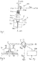
- Fig. 2 shows in a schematic cross-sectional view of essential portions of a sample combustion furnace (reaction module) 11 in an embodiment of the invention, in which a substantially elongated cylindrical stainless steel reaction vessel 13 (in the figure with a dashed line drawn outline) can be used. This one has at the bottom (Foot) a tubular outlet, which can be easily cleaned from below to eliminate salt deposits.
- the furnace 11 in the particular two zone configuration shown (which is only exemplified herein), has a first, upper heating zone 11a, in which a maximum temperature of 800 ° C can be achieved in this embodiment, and a second, lower heating zone 11b in which a maximum temperature of 1250 ° C is reached. Both heating zones are heated by hollow cylinders around the corresponding section of the reaction vessel 13 arranged heating modules 11c, 11d of a high temperature resistant special alloy, such as the material Kanthal Fibrothale heated.
- the heating modules 11c, 11d have microporous ceramic fiber insulation 11e and 11f, respectively, due to the different maximum temperatures, and also the foot area 119, the area 11 between the heating zones and the head area 11i, 11j below an aluminum lid 11k are ceramic fiber insulated , A sample charge and carrier gas supply means (not shown in the figure) is provided in the area above the lid 11k.
- the entire reaction module 11 is additionally sheathed with a macroporous outer insulation 11l, which significantly lowers both the temperature at the outer periphery of the furnace and at its head and foot, in the normal operation of the furnace to the values mentioned above.
- the incinerator 11 has a complex temperature sensor, which can also contribute to the achievement of this goal. This comprises in each case a T-sensor 11m, 11n arranged in the head and foot region and in each case one T sensor 11o, 11p assigned to the heating modules 11c, 11d. All T sensors are connected to corresponding inputs of a heating control and regulating device, which is based on the name of the controller 12 in Fig. 1 designated 12A.
- the detection signals of the T sensors are allocated in accordance with a stored optimization algorithm (if appropriate together with signals S INJ which characterize a sample injection process (see below) Actuated control signals for the heating modules 11c, 11d, which control the power supply to these and thus time-dependent heating of the heating zones 11a, 11b.
- a PID control algorithm is implemented in the heating control and regulating device 12a.
- Fig. 3 shows in a sketch in longitudinal section an exemplary structure and the coordinated geometric configuration of the injection syringe MM and the injection port P of the furnace 11 (FIG. Fig. 2 ) of the measuring arrangement 10 ( Fig. 1 ).
- the injection port P comprises a guide sleeve P1 that is substantially cylindrical in its longitudinal course and whose diameter and length are matched to the corresponding dimensions of an injection needle MM1 of the injection syringe MM and whose longitudinal axis coincides with a longitudinal axis LA1 of the furnace, which is cylindrical in its basic form.
- a guide sleeve P1 that is substantially cylindrical in its longitudinal course and whose diameter and length are matched to the corresponding dimensions of an injection needle MM1 of the injection syringe MM and whose longitudinal axis coincides with a longitudinal axis LA1 of the furnace, which is cylindrical in its basic form.
- an enlarged diameter bore P2 the dimensions of which are adapted to those of a needle hub MM2 of the syringe and whose lower end face acts as a depth limiting stop when the injection syringe is inserted.
- an O-ring P3 On the lower end face of the bore P2 is located as a seal, an O-ring P3, which can be designed in particular as a silicone ring with Teflon coating.
- a syringe piston MM4 is mounted longitudinally displaceable, the free end is designed in the usual way for manually mounting a sample.
- a compression spring MM5 is embedded, the upper end is supported against the upper end wall of the syringe reservoir and the lower end acts on the end of the syringe piston MM4.
- the syringe piston MM5 is locked by means of a locking lever MM5.
- the syringe piston MM4 is pressed down by the force of the compression spring MM5 and the sample contained in the syringe reservoir MM3 is injected into the furnace at a predetermined time interval or at a predetermined discharge speed.
- an adjustable stop or a different type of device for adjusting the position of the end of the injection needle may be provided in the oven, which may also play a role in the context of optimized temperature control.
- a position detector D INJ on the locking lever MM6 of the injection syringe MM which detects the position of the locking lever and thus the released release of the compression spring MM5 and thus again an initiated injection process.
- the detector D INJ supplies an injection input signal S INJ to the heating control device 12A ( Fig. 2 ) which can process this signal to provide a drive signal (timing and current) for the heating modules of the furnace.
- the timed or regulated heating of the furnace thus takes into account injection processes that can lead to "temperature surges" in the furnace, in the sense of smoothing the temporal temperature profile and avoiding temperature peaks above the desired maximum values at the bottom of the oven.
- a permanently installed at the injection port P 'supply pipe T is used in conjunction with a shut-off or three-way valve V instead of a movable syringe.
- the valve position and thus an ongoing injection process by means of a similar position detector D ' INJ as in Fig. 3 be detected, or it is on the supply pipe T a flow detector is provided which also detects an injection process and supplies a corresponding injection input signal for the heating control and regulating device of the measuring arrangement.
- the measuring arrangement may include a feed control device for controlling the sample injection, based on the name of the controller 12 in Fig. 1 designated by 12B.
- This can measure the temperature signals of individual or all T-sensors 11m to 11p ( Fig. 2 ) are supplied in order to differentiated controlled in response to the T-signals, ie from the current temperature status of the incinerator 11, injection operations by actuation of the valve.
Landscapes
- Life Sciences & Earth Sciences (AREA)
- Health & Medical Sciences (AREA)
- Chemical & Material Sciences (AREA)
- Physics & Mathematics (AREA)
- General Physics & Mathematics (AREA)
- Engineering & Computer Science (AREA)
- Immunology (AREA)
- Pathology (AREA)
- Analytical Chemistry (AREA)
- Biochemistry (AREA)
- General Health & Medical Sciences (AREA)
- Food Science & Technology (AREA)
- Medicinal Chemistry (AREA)
- Molecular Biology (AREA)
- Combustion & Propulsion (AREA)
- Biodiversity & Conservation Biology (AREA)
- Biomedical Technology (AREA)
- Emergency Medicine (AREA)
- Hydrology & Water Resources (AREA)
- Nuclear Medicine, Radiotherapy & Molecular Imaging (AREA)
- Investigating Or Analyzing Non-Biological Materials By The Use Of Chemical Means (AREA)
- Spectroscopy & Molecular Physics (AREA)
- Investigating Or Analyzing Materials Using Thermal Means (AREA)
- Investigating Or Analysing Materials By Optical Means (AREA)
Applications Claiming Priority (1)
| Application Number | Priority Date | Filing Date | Title |
|---|---|---|---|
| DE102018105611.7A DE102018105611A1 (de) | 2018-03-12 | 2018-03-12 | Messanordnung und Messverfahren zur Bestimmung eines Inhaltsstoffes oder Qualitätsparameters von Wasser oder Abwasser |
Publications (3)
| Publication Number | Publication Date |
|---|---|
| EP3540431A2 true EP3540431A2 (fr) | 2019-09-18 |
| EP3540431A3 EP3540431A3 (fr) | 2019-10-16 |
| EP3540431B1 EP3540431B1 (fr) | 2021-05-05 |
Family
ID=65995459
Family Applications (2)
| Application Number | Title | Priority Date | Filing Date |
|---|---|---|---|
| EP19162103.6A Active EP3540432B1 (fr) | 2018-03-12 | 2019-03-12 | Dispositif de mesure et procédé de mesure permettant de déterminer un ingrédient ou un paramètre de qualité de l'eau ou des eaux usées |
| EP19162102.8A Active EP3540431B1 (fr) | 2018-03-12 | 2019-03-12 | Dispositif de mesure et procédé de mesure permettant de déterminer un ingrédient ou un paramètre de qualité de l'eau ou des eaux usées |
Family Applications Before (1)
| Application Number | Title | Priority Date | Filing Date |
|---|---|---|---|
| EP19162103.6A Active EP3540432B1 (fr) | 2018-03-12 | 2019-03-12 | Dispositif de mesure et procédé de mesure permettant de déterminer un ingrédient ou un paramètre de qualité de l'eau ou des eaux usées |
Country Status (6)
| Country | Link |
|---|---|
| US (2) | US11243149B2 (fr) |
| EP (2) | EP3540432B1 (fr) |
| KR (2) | KR102204567B1 (fr) |
| CN (2) | CN110261557B (fr) |
| DE (1) | DE102018105611A1 (fr) |
| ES (2) | ES2883940T3 (fr) |
Families Citing this family (8)
| Publication number | Priority date | Publication date | Assignee | Title |
|---|---|---|---|---|
| WO2018189966A1 (fr) * | 2017-04-11 | 2018-10-18 | 株式会社島津製作所 | Dispositif d'extraction de constituants |
| KR102187689B1 (ko) * | 2020-06-09 | 2020-12-07 | 에이티티(주) | Toc 측정용 도가니 용광로구조 |
| EP4204801A1 (fr) * | 2020-08-28 | 2023-07-05 | Horiba Tocadero GmbH | Dispositif d'analyse d'eaux industrielles et son support |
| US20240027410A1 (en) * | 2020-08-28 | 2024-01-25 | HORIBA Tocadero GmbH | Reactor assembly for an industrial water analysis device |
| TW202235873A (zh) * | 2020-11-06 | 2022-09-16 | 美商Bl科技公司 | 具有整合的電導率測量功能的組合式傳輸模組 |
| KR102807378B1 (ko) * | 2022-06-22 | 2025-05-15 | 현대제철 주식회사 | 바이오매스 연소성 평가장치 |
| CN115452998A (zh) * | 2022-09-28 | 2022-12-09 | 煤炭科学技术研究院有限公司 | 一种确定水样中液压传动介质组分的方法 |
| CN116026667B (zh) * | 2022-12-20 | 2025-11-21 | 青岛理工大学 | 一种封装有微通道催化剂的总磷快速消解器及制作方法 |
Citations (10)
| Publication number | Priority date | Publication date | Assignee | Title |
|---|---|---|---|---|
| JPS59154358A (ja) | 1983-02-23 | 1984-09-03 | Shimadzu Corp | 全燐測定装置 |
| JPS61140863A (ja) | 1984-12-14 | 1986-06-27 | Fuji Electric Co Ltd | 水中の燐化合物の分析装置 |
| DE4344441C1 (de) | 1993-12-24 | 1995-07-13 | Siepmann Friedrich W | Verfahren und Vorrichtung zur kontinuierlichen Bestimmung des Gehalts an oxidierbaren Inhaltsstoffen in wäßrigen Flüssigkeiten |
| EP0684471A2 (fr) | 1994-05-27 | 1995-11-29 | Shimadzu Corporation | Dispositif de mesure de la teneur totale en carbone organique |
| US5702954A (en) | 1995-09-29 | 1997-12-30 | Colorado Seminary | Method to detect phosphorus |
| EP0887643A1 (fr) | 1997-06-24 | 1998-12-30 | LAR Analytik und Umweltmesstechnik GmbH | Procédé de détermination de la teneur de composants dans des systèmes aqueux |
| EP1055927A1 (fr) | 1999-05-03 | 2000-11-29 | LAR Analytik und Umweltmesstechnik GmbH | Procédé et dispositif pour la décomposition d'une solution liquide afin de déterminer la teneur en carbone |
| US20030032194A1 (en) | 1999-03-05 | 2003-02-13 | Wreyford Randy L. | Method for staged oxidation for enhanced nitrogen and sulfur detection |
| EP2115453A1 (fr) | 2007-01-29 | 2009-11-11 | LAR Process Analysers AG | Procédé et dispositif pour déterminer la teneur en phosphore d'un échantillon aqueux |
| WO2016091252A2 (fr) | 2014-12-08 | 2016-06-16 | Lar Process Analysers Ag | Système pour l'analyse d'eau et d'eaux usées |
Family Cites Families (22)
| Publication number | Priority date | Publication date | Assignee | Title |
|---|---|---|---|---|
| US3544277A (en) * | 1968-09-16 | 1970-12-01 | North American Rockwell | Dual heat zone pyrolytic furnace |
| US3939713A (en) * | 1975-02-28 | 1976-02-24 | The Perkin-Elmer Corporation | Septum mounting and shielding assembly for sample injection in an analytical instrument |
| US5246367A (en) * | 1989-06-23 | 1993-09-21 | Ricoh Elemex Corporation | Mouth cavity sanitary device |
| US5146793A (en) * | 1989-10-06 | 1992-09-15 | Millipore Corporation | Fluid seal |
| EP0509316B1 (fr) * | 1991-04-09 | 1994-12-14 | Schultz, Hans-Dieter | Dispositif pour mesurer des impuretés dans un liquide, notamment dans l'eau |
| DE4334434A1 (de) * | 1993-10-08 | 1995-04-13 | Hoechst Ag | Verfahren zum Überwachen von Wasser auf organische Verunreinigungen |
| US5697341A (en) * | 1995-11-20 | 1997-12-16 | Caterpillar, Inc. | Fill metered hydraulically actuated fuel injection system and method of fuel injection |
| KR100466303B1 (ko) * | 1996-05-03 | 2005-04-06 | 텔레다이 이스코 인코포레이티드 | 수성 액체 중의 산화성 물질의 함량을 측정하는 방법 및 장치 |
| US6770482B1 (en) * | 1999-07-16 | 2004-08-03 | General Electric | Method and apparatus for rapid screening of multiphase reactions |
| DE10240410B3 (de) * | 2002-09-02 | 2004-02-05 | Lar Analytik Und Umweltmesstechnik Gmbh | Verfahren zur Bestimmung des Sauerstoffbedarfs einer wässrigen Lösung für einen Klärprozess |
| DE10360445A1 (de) * | 2003-12-22 | 2005-07-28 | Lar Analytik & Umweltmesstechnik Gmbh | Verfahren und Anordnung zur Bestimmung von Wasserinhaltsstoffen |
| KR100703762B1 (ko) * | 2006-08-11 | 2007-04-09 | 이상득 | 밸브용 실란트 피팅 |
| US20110020568A1 (en) * | 2007-03-28 | 2011-01-27 | Igor Aleksandrovich Danchenko | Method for wood heat treatment and a device for carrying out said method |
| DE102008007354B4 (de) * | 2008-01-29 | 2009-11-19 | Stiftung Alfred-Wegener-Institut Für Polar- Und Meeresforschung | Hochtemperatur-Rohrofen für die Pyrolyse |
| DE102008025877A1 (de) * | 2008-05-29 | 2009-12-03 | Endress + Hauser Conducta Gesellschaft für Mess- und Regeltechnik mbH + Co. KG | Vorrichtung zur Bestimmung des Gehalts an mindestens einem oxidierbaren Inhaltsstoff in einer wässrigen Flüssigkeitsprobe |
| EP2450703A1 (fr) * | 2010-11-08 | 2012-05-09 | FATAX GmbH | Dispositif et procédé de détermination commune d'azote d'ammonium, azote total et carbone organique total |
| CN103776805B (zh) * | 2012-10-17 | 2016-06-15 | 北京瑞利分析仪器有限公司 | 恒温蒸气发生进样系统 |
| DE202014102443U1 (de) * | 2014-05-26 | 2015-05-27 | Lar Process Analysers Ag | Analysegerät zur Wasser- und Abwasseranalyse |
| DE102014111506A1 (de) * | 2014-08-12 | 2016-02-18 | Analytik Jena Ag | Analysegerät zur Bestimmung einer von der Konzentration eines oder mehrerer Inhaltsstoffe einer Probe abhängigen Messgröße |
| KR101718945B1 (ko) * | 2015-03-13 | 2017-03-23 | 이종철 | 개스킷 및 이의 제작 방법 |
| DE102015118586A1 (de) * | 2015-10-30 | 2017-05-04 | Lar Process Analysers Ag | Probenverdünnung |
| JP6631817B2 (ja) * | 2018-03-30 | 2020-01-15 | 株式会社エコロ | Toc計測方法及びそれに使用するtoc計測装置 |
-
2018
- 2018-03-12 DE DE102018105611.7A patent/DE102018105611A1/de not_active Withdrawn
-
2019
- 2019-03-11 KR KR1020190027541A patent/KR102204567B1/ko active Active
- 2019-03-11 KR KR1020190027525A patent/KR102208612B1/ko active Active
- 2019-03-12 ES ES19162102T patent/ES2883940T3/es active Active
- 2019-03-12 CN CN201910184719.8A patent/CN110261557B/zh active Active
- 2019-03-12 CN CN201910183901.1A patent/CN110261556A/zh active Pending
- 2019-03-12 EP EP19162103.6A patent/EP3540432B1/fr active Active
- 2019-03-12 EP EP19162102.8A patent/EP3540431B1/fr active Active
- 2019-03-12 US US16/299,758 patent/US11243149B2/en active Active
- 2019-03-12 ES ES19162103T patent/ES2882912T3/es active Active
- 2019-03-12 US US16/299,741 patent/US11221282B2/en active Active
Patent Citations (10)
| Publication number | Priority date | Publication date | Assignee | Title |
|---|---|---|---|---|
| JPS59154358A (ja) | 1983-02-23 | 1984-09-03 | Shimadzu Corp | 全燐測定装置 |
| JPS61140863A (ja) | 1984-12-14 | 1986-06-27 | Fuji Electric Co Ltd | 水中の燐化合物の分析装置 |
| DE4344441C1 (de) | 1993-12-24 | 1995-07-13 | Siepmann Friedrich W | Verfahren und Vorrichtung zur kontinuierlichen Bestimmung des Gehalts an oxidierbaren Inhaltsstoffen in wäßrigen Flüssigkeiten |
| EP0684471A2 (fr) | 1994-05-27 | 1995-11-29 | Shimadzu Corporation | Dispositif de mesure de la teneur totale en carbone organique |
| US5702954A (en) | 1995-09-29 | 1997-12-30 | Colorado Seminary | Method to detect phosphorus |
| EP0887643A1 (fr) | 1997-06-24 | 1998-12-30 | LAR Analytik und Umweltmesstechnik GmbH | Procédé de détermination de la teneur de composants dans des systèmes aqueux |
| US20030032194A1 (en) | 1999-03-05 | 2003-02-13 | Wreyford Randy L. | Method for staged oxidation for enhanced nitrogen and sulfur detection |
| EP1055927A1 (fr) | 1999-05-03 | 2000-11-29 | LAR Analytik und Umweltmesstechnik GmbH | Procédé et dispositif pour la décomposition d'une solution liquide afin de déterminer la teneur en carbone |
| EP2115453A1 (fr) | 2007-01-29 | 2009-11-11 | LAR Process Analysers AG | Procédé et dispositif pour déterminer la teneur en phosphore d'un échantillon aqueux |
| WO2016091252A2 (fr) | 2014-12-08 | 2016-06-16 | Lar Process Analysers Ag | Système pour l'analyse d'eau et d'eaux usées |
Also Published As
| Publication number | Publication date |
|---|---|
| EP3540432B1 (fr) | 2021-05-19 |
| EP3540431B1 (fr) | 2021-05-05 |
| EP3540431A3 (fr) | 2019-10-16 |
| US11221282B2 (en) | 2022-01-11 |
| ES2883940T3 (es) | 2021-12-09 |
| US11243149B2 (en) | 2022-02-08 |
| KR102204567B1 (ko) | 2021-01-18 |
| EP3540432A3 (fr) | 2020-01-01 |
| US20190277818A1 (en) | 2019-09-12 |
| US20190277737A1 (en) | 2019-09-12 |
| ES2882912T3 (es) | 2021-12-03 |
| KR20190107586A (ko) | 2019-09-20 |
| DE102018105611A1 (de) | 2019-09-12 |
| KR20190107587A (ko) | 2019-09-20 |
| KR102208612B1 (ko) | 2021-01-27 |
| CN110261557B (zh) | 2023-06-20 |
| EP3540432A2 (fr) | 2019-09-18 |
| CN110261556A (zh) | 2019-09-20 |
| CN110261557A (zh) | 2019-09-20 |
Similar Documents
| Publication | Publication Date | Title |
|---|---|---|
| EP3540431B1 (fr) | Dispositif de mesure et procédé de mesure permettant de déterminer un ingrédient ou un paramètre de qualité de l'eau ou des eaux usées | |
| DE2524703C2 (de) | Verfahren und Vorrichtung zum Überwachen der Octanzahl eines Benzinstromes | |
| DE10354440B4 (de) | Fluidleckageerfassungsgerät und Fluidleckageerfassungsverfahren | |
| EP0803731B1 (fr) | Méthode et appareil pour la détermination en continu de produits d'oxydation en forme de gaz | |
| EP2310117B1 (fr) | Procédé et dispositif de gazéification d'un liquide, par exemple d'une boisson | |
| DE2656398A1 (de) | Heiz- und kuehlkammer fuer chromatographiesaeulen | |
| EP2366485B1 (fr) | Appareil de soudage à l'arc muni d'une torche à refroidissement liquide controllé | |
| DE10360066A1 (de) | Verfahren zur fotometrischen Bestimmung eines Parameters | |
| CH670160A5 (fr) | ||
| EP2115453B1 (fr) | Procédé et dispositif pour déterminer la teneur en phosphore d'un échantillon aqueux | |
| EP0507169A2 (fr) | Système d'introduction d'échantillons avec four à micro-ondes | |
| EP3377889B1 (fr) | Appareil d'analyse et procédé | |
| DE2704551A1 (de) | Temperatursteuersystem | |
| DE1598351B2 (de) | Verfahren zur Bestimmung des Sauerstoffbedarfs einer wäßrigen Dispersion und Vorrichtung zur Durchführung des Verfahrens | |
| DE3801410A1 (de) | Kraftstoffaufbereitungsvorrichtung | |
| DE3448091C2 (de) | Kalt-Probenaufgabesystem für die Kapillargaschromatographie | |
| WO1994016791A1 (fr) | Procede d'extraction par solvant et unite d'extraction a cet effet, ainsi qu'appareil en ligne realise avec de telles unites d'extraction, notamment avec recuperation du solvant | |
| AT513317B1 (de) | Druckreaktor | |
| DE4435821A1 (de) | Verfahren und Vorrichtung zur Herstellung einer Chlordioxid-Lösung | |
| DE4412778C1 (de) | Verfahren und Vorrichtung zur Analyse einer wässrigen Probe | |
| DE19604606A1 (de) | Meßvorrichtung für einen von wenigstens zwei flüchtigen Bestandteilen einer Flüssigkeit, insbesondere einer Fermentationsflüssigkeit | |
| DE102008055853B4 (de) | Verfahren zum Erwärmen und Reinigen eines Fluids und entsprechende Vorrichtung | |
| DE19617910B4 (de) | Verfahren und Vorrichtung zur Bestimmung des Gehalts an oxidierbaren Inhaltsstoffen in wässrigen Flüssigkeiten | |
| WO2009112199A1 (fr) | Dispositif de mesure et montage de mesure pour déterminer la teneur de l'eau fraîche ou d'une eau résiduaire en un élément chimique ou en un autre paramètre de qualité de l'eau | |
| DE102025135761A1 (de) | Steuergerät für keramische Heizelementmodule, keramische Heizelementeinheit, und Steuerprogramm für keramische Heizelementmodule |
Legal Events
| Date | Code | Title | Description |
|---|---|---|---|
| PUAI | Public reference made under article 153(3) epc to a published international application that has entered the european phase |
Free format text: ORIGINAL CODE: 0009012 |
|
| STAA | Information on the status of an ep patent application or granted ep patent |
Free format text: STATUS: REQUEST FOR EXAMINATION WAS MADE |
|
| PUAL | Search report despatched |
Free format text: ORIGINAL CODE: 0009013 |
|
| 17P | Request for examination filed |
Effective date: 20190312 |
|
| AK | Designated contracting states |
Kind code of ref document: A2 Designated state(s): AL AT BE BG CH CY CZ DE DK EE ES FI FR GB GR HR HU IE IS IT LI LT LU LV MC MK MT NL NO PL PT RO RS SE SI SK SM TR |
|
| AX | Request for extension of the european patent |
Extension state: BA ME |
|
| AK | Designated contracting states |
Kind code of ref document: A3 Designated state(s): AL AT BE BG CH CY CZ DE DK EE ES FI FR GB GR HR HU IE IS IT LI LT LU LV MC MK MT NL NO PL PT RO RS SE SI SK SM TR |
|
| AX | Request for extension of the european patent |
Extension state: BA ME |
|
| RIC1 | Information provided on ipc code assigned before grant |
Ipc: G01N 33/18 20060101AFI20190911BHEP Ipc: G01N 31/12 20060101ALI20190911BHEP |
|
| STAA | Information on the status of an ep patent application or granted ep patent |
Free format text: STATUS: EXAMINATION IS IN PROGRESS |
|
| 17Q | First examination report despatched |
Effective date: 20200514 |
|
| GRAP | Despatch of communication of intention to grant a patent |
Free format text: ORIGINAL CODE: EPIDOSNIGR1 |
|
| STAA | Information on the status of an ep patent application or granted ep patent |
Free format text: STATUS: GRANT OF PATENT IS INTENDED |
|
| INTG | Intention to grant announced |
Effective date: 20210112 |
|
| GRAS | Grant fee paid |
Free format text: ORIGINAL CODE: EPIDOSNIGR3 |
|
| GRAA | (expected) grant |
Free format text: ORIGINAL CODE: 0009210 |
|
| STAA | Information on the status of an ep patent application or granted ep patent |
Free format text: STATUS: THE PATENT HAS BEEN GRANTED |
|
| AK | Designated contracting states |
Kind code of ref document: B1 Designated state(s): AL AT BE BG CH CY CZ DE DK EE ES FI FR GB GR HR HU IE IS IT LI LT LU LV MC MK MT NL NO PL PT RO RS SE SI SK SM TR |
|
| REG | Reference to a national code |
Ref country code: GB Ref legal event code: FG4D Free format text: NOT ENGLISH |
|
| REG | Reference to a national code |
Ref country code: CH Ref legal event code: EP |
|
| REG | Reference to a national code |
Ref country code: AT Ref legal event code: REF Ref document number: 1390438 Country of ref document: AT Kind code of ref document: T Effective date: 20210515 |
|
| REG | Reference to a national code |
Ref country code: DE Ref legal event code: R096 Ref document number: 502019001337 Country of ref document: DE |
|
| REG | Reference to a national code |
Ref country code: IE Ref legal event code: FG4D Free format text: LANGUAGE OF EP DOCUMENT: GERMAN |
|
| REG | Reference to a national code |
Ref country code: NL Ref legal event code: FP |
|
| REG | Reference to a national code |
Ref country code: LT Ref legal event code: MG9D |
|
| PG25 | Lapsed in a contracting state [announced via postgrant information from national office to epo] |
Ref country code: BG Free format text: LAPSE BECAUSE OF FAILURE TO SUBMIT A TRANSLATION OF THE DESCRIPTION OR TO PAY THE FEE WITHIN THE PRESCRIBED TIME-LIMIT Effective date: 20210805 Ref country code: FI Free format text: LAPSE BECAUSE OF FAILURE TO SUBMIT A TRANSLATION OF THE DESCRIPTION OR TO PAY THE FEE WITHIN THE PRESCRIBED TIME-LIMIT Effective date: 20210505 Ref country code: HR Free format text: LAPSE BECAUSE OF FAILURE TO SUBMIT A TRANSLATION OF THE DESCRIPTION OR TO PAY THE FEE WITHIN THE PRESCRIBED TIME-LIMIT Effective date: 20210505 Ref country code: LT Free format text: LAPSE BECAUSE OF FAILURE TO SUBMIT A TRANSLATION OF THE DESCRIPTION OR TO PAY THE FEE WITHIN THE PRESCRIBED TIME-LIMIT Effective date: 20210505 |
|
| PG25 | Lapsed in a contracting state [announced via postgrant information from national office to epo] |
Ref country code: IS Free format text: LAPSE BECAUSE OF FAILURE TO SUBMIT A TRANSLATION OF THE DESCRIPTION OR TO PAY THE FEE WITHIN THE PRESCRIBED TIME-LIMIT Effective date: 20210905 Ref country code: GR Free format text: LAPSE BECAUSE OF FAILURE TO SUBMIT A TRANSLATION OF THE DESCRIPTION OR TO PAY THE FEE WITHIN THE PRESCRIBED TIME-LIMIT Effective date: 20210806 Ref country code: PL Free format text: LAPSE BECAUSE OF FAILURE TO SUBMIT A TRANSLATION OF THE DESCRIPTION OR TO PAY THE FEE WITHIN THE PRESCRIBED TIME-LIMIT Effective date: 20210505 Ref country code: NO Free format text: LAPSE BECAUSE OF FAILURE TO SUBMIT A TRANSLATION OF THE DESCRIPTION OR TO PAY THE FEE WITHIN THE PRESCRIBED TIME-LIMIT Effective date: 20210805 Ref country code: LV Free format text: LAPSE BECAUSE OF FAILURE TO SUBMIT A TRANSLATION OF THE DESCRIPTION OR TO PAY THE FEE WITHIN THE PRESCRIBED TIME-LIMIT Effective date: 20210505 Ref country code: PT Free format text: LAPSE BECAUSE OF FAILURE TO SUBMIT A TRANSLATION OF THE DESCRIPTION OR TO PAY THE FEE WITHIN THE PRESCRIBED TIME-LIMIT Effective date: 20210906 Ref country code: RS Free format text: LAPSE BECAUSE OF FAILURE TO SUBMIT A TRANSLATION OF THE DESCRIPTION OR TO PAY THE FEE WITHIN THE PRESCRIBED TIME-LIMIT Effective date: 20210505 Ref country code: SE Free format text: LAPSE BECAUSE OF FAILURE TO SUBMIT A TRANSLATION OF THE DESCRIPTION OR TO PAY THE FEE WITHIN THE PRESCRIBED TIME-LIMIT Effective date: 20210505 |
|
| REG | Reference to a national code |
Ref country code: ES Ref legal event code: FG2A Ref document number: 2883940 Country of ref document: ES Kind code of ref document: T3 Effective date: 20211209 |
|
| PG25 | Lapsed in a contracting state [announced via postgrant information from national office to epo] |
Ref country code: CZ Free format text: LAPSE BECAUSE OF FAILURE TO SUBMIT A TRANSLATION OF THE DESCRIPTION OR TO PAY THE FEE WITHIN THE PRESCRIBED TIME-LIMIT Effective date: 20210505 Ref country code: DK Free format text: LAPSE BECAUSE OF FAILURE TO SUBMIT A TRANSLATION OF THE DESCRIPTION OR TO PAY THE FEE WITHIN THE PRESCRIBED TIME-LIMIT Effective date: 20210505 Ref country code: SM Free format text: LAPSE BECAUSE OF FAILURE TO SUBMIT A TRANSLATION OF THE DESCRIPTION OR TO PAY THE FEE WITHIN THE PRESCRIBED TIME-LIMIT Effective date: 20210505 Ref country code: RO Free format text: LAPSE BECAUSE OF FAILURE TO SUBMIT A TRANSLATION OF THE DESCRIPTION OR TO PAY THE FEE WITHIN THE PRESCRIBED TIME-LIMIT Effective date: 20210505 Ref country code: SK Free format text: LAPSE BECAUSE OF FAILURE TO SUBMIT A TRANSLATION OF THE DESCRIPTION OR TO PAY THE FEE WITHIN THE PRESCRIBED TIME-LIMIT Effective date: 20210505 Ref country code: EE Free format text: LAPSE BECAUSE OF FAILURE TO SUBMIT A TRANSLATION OF THE DESCRIPTION OR TO PAY THE FEE WITHIN THE PRESCRIBED TIME-LIMIT Effective date: 20210505 |
|
| REG | Reference to a national code |
Ref country code: DE Ref legal event code: R097 Ref document number: 502019001337 Country of ref document: DE |
|
| PLBE | No opposition filed within time limit |
Free format text: ORIGINAL CODE: 0009261 |
|
| STAA | Information on the status of an ep patent application or granted ep patent |
Free format text: STATUS: NO OPPOSITION FILED WITHIN TIME LIMIT |
|
| 26N | No opposition filed |
Effective date: 20220208 |
|
| PG25 | Lapsed in a contracting state [announced via postgrant information from national office to epo] |
Ref country code: IS Free format text: LAPSE BECAUSE OF FAILURE TO SUBMIT A TRANSLATION OF THE DESCRIPTION OR TO PAY THE FEE WITHIN THE PRESCRIBED TIME-LIMIT Effective date: 20210905 Ref country code: AL Free format text: LAPSE BECAUSE OF FAILURE TO SUBMIT A TRANSLATION OF THE DESCRIPTION OR TO PAY THE FEE WITHIN THE PRESCRIBED TIME-LIMIT Effective date: 20210505 |
|
| PG25 | Lapsed in a contracting state [announced via postgrant information from national office to epo] |
Ref country code: MC Free format text: LAPSE BECAUSE OF FAILURE TO SUBMIT A TRANSLATION OF THE DESCRIPTION OR TO PAY THE FEE WITHIN THE PRESCRIBED TIME-LIMIT Effective date: 20210505 |
|
| PG25 | Lapsed in a contracting state [announced via postgrant information from national office to epo] |
Ref country code: LU Free format text: LAPSE BECAUSE OF NON-PAYMENT OF DUE FEES Effective date: 20220312 |
|
| REG | Reference to a national code |
Ref country code: DE Ref legal event code: R081 Ref document number: 502019001337 Country of ref document: DE Owner name: PROCESS INSIGHTS AG, DE Free format text: FORMER OWNER: LAR PROCESS ANALYSERS AG, 12057 BERLIN, DE |
|
| REG | Reference to a national code |
Ref country code: NL Ref legal event code: HC Owner name: PROCESS INSIGHTS AG; DE Free format text: DETAILS ASSIGNMENT: CHANGE OF OWNER(S), CHANGE OF OWNER(S) NAME; FORMER OWNER NAME: LAR PROCESS ANALYSERS AG Effective date: 20230915 |
|
| REG | Reference to a national code |
Ref country code: BE Ref legal event code: HC Owner name: PROCESS INSIGHTS AG; DE Free format text: DETAILS ASSIGNMENT: CHANGE OF OWNER(S), CHANGE OF OWNER(S) NAME; FORMER OWNER NAME: LAR PROCESS ANALYSERS AG Effective date: 20230913 |
|
| REG | Reference to a national code |
Ref country code: CH Ref legal event code: PK Free format text: BERICHTIGUNGEN |
|
| REG | Reference to a national code |
Ref country code: CH Ref legal event code: PK Free format text: BEIM REGISTEREINTRAG VOM 11.10.2023 HANDELT ES SICH NICHT UM EINE FUSION SONDERN UM EINE FIRMENAENDERUNG |
|
| REG | Reference to a national code |
Ref country code: AT Ref legal event code: HC Ref document number: 1390438 Country of ref document: AT Kind code of ref document: T Owner name: PROCESS INSIGHTS AG, DE Effective date: 20231114 |
|
| PG25 | Lapsed in a contracting state [announced via postgrant information from national office to epo] |
Ref country code: MK Free format text: LAPSE BECAUSE OF FAILURE TO SUBMIT A TRANSLATION OF THE DESCRIPTION OR TO PAY THE FEE WITHIN THE PRESCRIBED TIME-LIMIT Effective date: 20210505 Ref country code: CY Free format text: LAPSE BECAUSE OF FAILURE TO SUBMIT A TRANSLATION OF THE DESCRIPTION OR TO PAY THE FEE WITHIN THE PRESCRIBED TIME-LIMIT Effective date: 20210505 |
|
| PG25 | Lapsed in a contracting state [announced via postgrant information from national office to epo] |
Ref country code: HU Free format text: LAPSE BECAUSE OF FAILURE TO SUBMIT A TRANSLATION OF THE DESCRIPTION OR TO PAY THE FEE WITHIN THE PRESCRIBED TIME-LIMIT; INVALID AB INITIO Effective date: 20190312 |
|
| REG | Reference to a national code |
Ref country code: ES Ref legal event code: PC2A Owner name: PROCESS INSIGHTS AG Effective date: 20240617 |
|
| PG25 | Lapsed in a contracting state [announced via postgrant information from national office to epo] |
Ref country code: TR Free format text: LAPSE BECAUSE OF FAILURE TO SUBMIT A TRANSLATION OF THE DESCRIPTION OR TO PAY THE FEE WITHIN THE PRESCRIBED TIME-LIMIT Effective date: 20210505 |
|
| PG25 | Lapsed in a contracting state [announced via postgrant information from national office to epo] |
Ref country code: MT Free format text: LAPSE BECAUSE OF FAILURE TO SUBMIT A TRANSLATION OF THE DESCRIPTION OR TO PAY THE FEE WITHIN THE PRESCRIBED TIME-LIMIT Effective date: 20210505 |
|
| REG | Reference to a national code |
Ref country code: CH Ref legal event code: U11 Free format text: ST27 STATUS EVENT CODE: U-0-0-U10-U11 (AS PROVIDED BY THE NATIONAL OFFICE) Effective date: 20260401 |
|
| PGFP | Annual fee paid to national office [announced via postgrant information from national office to epo] |
Ref country code: GB Payment date: 20260304 Year of fee payment: 8 |
|
| PGFP | Annual fee paid to national office [announced via postgrant information from national office to epo] |
Ref country code: IE Payment date: 20260318 Year of fee payment: 8 |
|
| PGFP | Annual fee paid to national office [announced via postgrant information from national office to epo] |
Ref country code: AT Payment date: 20260318 Year of fee payment: 8 |
|
| PGFP | Annual fee paid to national office [announced via postgrant information from national office to epo] |
Ref country code: BE Payment date: 20260323 Year of fee payment: 8 Ref country code: IT Payment date: 20260320 Year of fee payment: 8 |
|
| PGFP | Annual fee paid to national office [announced via postgrant information from national office to epo] |
Ref country code: NL Payment date: 20260323 Year of fee payment: 8 |
|
| PGFP | Annual fee paid to national office [announced via postgrant information from national office to epo] |
Ref country code: FR Payment date: 20260323 Year of fee payment: 8 |
|
| PGFP | Annual fee paid to national office [announced via postgrant information from national office to epo] |
Ref country code: ES Payment date: 20260414 Year of fee payment: 8 |
|
| PGFP | Annual fee paid to national office [announced via postgrant information from national office to epo] |
Ref country code: DE Payment date: 20260330 Year of fee payment: 8 |
|
| PGFP | Annual fee paid to national office [announced via postgrant information from national office to epo] |
Ref country code: CH Payment date: 20260401 Year of fee payment: 8 |