EP3540541B1 - Procédé, dispositif et programme de commande - Google Patents
Procédé, dispositif et programme de commande Download PDFInfo
- Publication number
- EP3540541B1 EP3540541B1 EP19151156.7A EP19151156A EP3540541B1 EP 3540541 B1 EP3540541 B1 EP 3540541B1 EP 19151156 A EP19151156 A EP 19151156A EP 3540541 B1 EP3540541 B1 EP 3540541B1
- Authority
- EP
- European Patent Office
- Prior art keywords
- axis
- master device
- slave device
- command value
- synchronization
- Prior art date
- Legal status (The legal status is an assumption and is not a legal conclusion. Google has not performed a legal analysis and makes no representation as to the accuracy of the status listed.)
- Not-in-force
Links
Images


Classifications
-
- G—PHYSICS
- G05—CONTROLLING; REGULATING
- G05B—CONTROL OR REGULATING SYSTEMS IN GENERAL; FUNCTIONAL ELEMENTS OF SUCH SYSTEMS; MONITORING OR TESTING ARRANGEMENTS FOR SUCH SYSTEMS OR ELEMENTS
- G05B19/00—Program-control systems
- G05B19/02—Program-control systems electric
- G05B19/418—Total factory control, i.e. centrally controlling a plurality of machines, e.g. direct or distributed numerical control [DNC], flexible manufacturing systems [FMS], integrated manufacturing systems [IMS] or computer integrated manufacturing [CIM]
- G05B19/41815—Total factory control, i.e. centrally controlling a plurality of machines, e.g. direct or distributed numerical control [DNC], flexible manufacturing systems [FMS], integrated manufacturing systems [IMS] or computer integrated manufacturing [CIM] characterised by the cooperation between machine tools, manipulators and conveyor or other workpiece supply system, workcell
- G05B19/4182—Total factory control, i.e. centrally controlling a plurality of machines, e.g. direct or distributed numerical control [DNC], flexible manufacturing systems [FMS], integrated manufacturing systems [IMS] or computer integrated manufacturing [CIM] characterised by the cooperation between machine tools, manipulators and conveyor or other workpiece supply system, workcell manipulators and conveyor only
-
- B—PERFORMING OPERATIONS; TRANSPORTING
- B25—HAND TOOLS; PORTABLE POWER-DRIVEN TOOLS; MANIPULATORS
- B25J—MANIPULATORS; CHAMBERS PROVIDED WITH MANIPULATION DEVICES
- B25J3/00—Manipulators of leader-follower type, i.e. both controlling unit and controlled unit perform corresponding spatial movements
-
- B—PERFORMING OPERATIONS; TRANSPORTING
- B25—HAND TOOLS; PORTABLE POWER-DRIVEN TOOLS; MANIPULATORS
- B25J—MANIPULATORS; CHAMBERS PROVIDED WITH MANIPULATION DEVICES
- B25J9/00—Program-controlled manipulators
- B25J9/02—Program-controlled manipulators characterised by movement of the arms, e.g. cartesian coordinate type
-
- B—PERFORMING OPERATIONS; TRANSPORTING
- B25—HAND TOOLS; PORTABLE POWER-DRIVEN TOOLS; MANIPULATORS
- B25J—MANIPULATORS; CHAMBERS PROVIDED WITH MANIPULATION DEVICES
- B25J9/00—Program-controlled manipulators
- B25J9/16—Program controls
-
- B—PERFORMING OPERATIONS; TRANSPORTING
- B25—HAND TOOLS; PORTABLE POWER-DRIVEN TOOLS; MANIPULATORS
- B25J—MANIPULATORS; CHAMBERS PROVIDED WITH MANIPULATION DEVICES
- B25J9/00—Program-controlled manipulators
- B25J9/16—Program controls
- B25J9/1628—Program controls characterised by the control loop
-
- G—PHYSICS
- G05—CONTROLLING; REGULATING
- G05B—CONTROL OR REGULATING SYSTEMS IN GENERAL; FUNCTIONAL ELEMENTS OF SUCH SYSTEMS; MONITORING OR TESTING ARRANGEMENTS FOR SUCH SYSTEMS OR ELEMENTS
- G05B19/00—Program-control systems
- G05B19/02—Program-control systems electric
- G05B19/04—Program control other than numerical control, i.e. in sequence controllers or logic controllers
-
- G—PHYSICS
- G05—CONTROLLING; REGULATING
- G05B—CONTROL OR REGULATING SYSTEMS IN GENERAL; FUNCTIONAL ELEMENTS OF SUCH SYSTEMS; MONITORING OR TESTING ARRANGEMENTS FOR SUCH SYSTEMS OR ELEMENTS
- G05B19/00—Program-control systems
- G05B19/02—Program-control systems electric
- G05B19/18—Numerical control [NC], i.e. automatically operating machines, in particular machine tools, e.g. in a manufacturing environment, so as to execute positioning, movement or co-ordinated operations by means of program data in numerical form
- G05B19/408—Numerical control [NC], i.e. automatically operating machines, in particular machine tools, e.g. in a manufacturing environment, so as to execute positioning, movement or co-ordinated operations by means of program data in numerical form characterised by data handling or data format, e.g. reading, buffering or conversion of data
- G05B19/4086—Coordinate conversions; Other special calculations
-
- G—PHYSICS
- G05—CONTROLLING; REGULATING
- G05B—CONTROL OR REGULATING SYSTEMS IN GENERAL; FUNCTIONAL ELEMENTS OF SUCH SYSTEMS; MONITORING OR TESTING ARRANGEMENTS FOR SUCH SYSTEMS OR ELEMENTS
- G05B19/00—Program-control systems
- G05B19/02—Program-control systems electric
- G05B19/18—Numerical control [NC], i.e. automatically operating machines, in particular machine tools, e.g. in a manufacturing environment, so as to execute positioning, movement or co-ordinated operations by means of program data in numerical form
- G05B19/41—Numerical control [NC], i.e. automatically operating machines, in particular machine tools, e.g. in a manufacturing environment, so as to execute positioning, movement or co-ordinated operations by means of program data in numerical form characterised by interpolation, e.g. the computation of intermediate points between programmed end points to define the path to be followed and the rate of travel along that path
-
- G—PHYSICS
- G05—CONTROLLING; REGULATING
- G05B—CONTROL OR REGULATING SYSTEMS IN GENERAL; FUNCTIONAL ELEMENTS OF SUCH SYSTEMS; MONITORING OR TESTING ARRANGEMENTS FOR SUCH SYSTEMS OR ELEMENTS
- G05B19/00—Program-control systems
- G05B19/02—Program-control systems electric
- G05B19/418—Total factory control, i.e. centrally controlling a plurality of machines, e.g. direct or distributed numerical control [DNC], flexible manufacturing systems [FMS], integrated manufacturing systems [IMS] or computer integrated manufacturing [CIM]
- G05B19/41815—Total factory control, i.e. centrally controlling a plurality of machines, e.g. direct or distributed numerical control [DNC], flexible manufacturing systems [FMS], integrated manufacturing systems [IMS] or computer integrated manufacturing [CIM] characterised by the cooperation between machine tools, manipulators and conveyor or other workpiece supply system, workcell
-
- G—PHYSICS
- G05—CONTROLLING; REGULATING
- G05B—CONTROL OR REGULATING SYSTEMS IN GENERAL; FUNCTIONAL ELEMENTS OF SUCH SYSTEMS; MONITORING OR TESTING ARRANGEMENTS FOR SUCH SYSTEMS OR ELEMENTS
- G05B2219/00—Program-control systems
- G05B2219/10—Plc systems
- G05B2219/12—Plc mp multi processor system
- G05B2219/1215—Leader-follower system
-
- G—PHYSICS
- G05—CONTROLLING; REGULATING
- G05B—CONTROL OR REGULATING SYSTEMS IN GENERAL; FUNCTIONAL ELEMENTS OF SUCH SYSTEMS; MONITORING OR TESTING ARRANGEMENTS FOR SUCH SYSTEMS OR ELEMENTS
- G05B2219/00—Program-control systems
- G05B2219/30—Nc systems
- G05B2219/42—Servomotor, servo controller kind till VSS
- G05B2219/42186—Leader-follower, motion proportional to axis
-
- G—PHYSICS
- G05—CONTROLLING; REGULATING
- G05B—CONTROL OR REGULATING SYSTEMS IN GENERAL; FUNCTIONAL ELEMENTS OF SUCH SYSTEMS; MONITORING OR TESTING ARRANGEMENTS FOR SUCH SYSTEMS OR ELEMENTS
- G05B2219/00—Program-control systems
- G05B2219/30—Nc systems
- G05B2219/42—Servomotor, servo controller kind till VSS
- G05B2219/42188—Follower controlled as function of reference and actual position and derived speed of leader
-
- Y—GENERAL TAGGING OF NEW TECHNOLOGICAL DEVELOPMENTS; GENERAL TAGGING OF CROSS-SECTIONAL TECHNOLOGIES SPANNING OVER SEVERAL SECTIONS OF THE IPC; TECHNICAL SUBJECTS COVERED BY FORMER USPC CROSS-REFERENCE ART COLLECTIONS [XRACs] AND DIGESTS
- Y02—TECHNOLOGIES OR APPLICATIONS FOR MITIGATION OR ADAPTATION AGAINST CLIMATE CHANGE
- Y02P—CLIMATE CHANGE MITIGATION TECHNOLOGIES IN THE PRODUCTION OR PROCESSING OF GOODS
- Y02P90/00—Enabling technologies with a potential contribution to greenhouse gas [GHG] emissions mitigation
- Y02P90/02—Total factory control, e.g. smart factories, flexible manufacturing systems [FMS] or integrated manufacturing systems [IMS]
Definitions
- the present disclosure relates to a control device, and more specifically, to a control device which synchronizes a master device with a slave device and controls the master device and the slave device.
- the present invention relates to a control method and a program for performing such control.
- a device which adds, as a correction amount (correction synchronization data), synchronization data to a position command value for a slave device in order to perform a coordinated operation of a master device (coordination reference) and the slave device (control target) as disclosed in Patent Document 1 (Japanese Patent Application Laid-open No. H06-138920 ) is known.
- Patent Document 1 Japanese Patent Application Laid-open No. H06-138920
- JP H03142180 A discloses a positional information converting means which algebraically converts the positional information measured by a position detecting means of a master side manipulator into the aiming positional information of each axis of a slave side.
- EP 2144127 A1 discloses a method comprising carrying an object to be picked by a conveyor device.
- a pickup of a multi-axis handling device is synchronized with the moving conveyor device for displacing the object, where the pickup is synchronized along computationally-determined polynomial path of third order between a starting point and a destination point.
- the polynomial path of third order is defined by the starting point, the destination point and tangential vectors in the starting point and the destination point.
- the applicant has developed a method of synchronizing a master device with a slave device to control the master device and the slave device by obtaining a command value for each axis of the slave device through an arithmetic operation at a fixed period (e.g., a period of about 0.5 msec to 1 msec) based on a command value for each axis (which refers to a "control axis" throughout the description) of the master device. Accordingly, it is possible to synchronize the master device with the slave device with high accuracy.
- a fixed period e.g., a period of about 0.5 msec to 1 msec
- the amount of calculations for a synchronization operation for maintaining the position of the master device and the position of the slave device in a predetermined corresponding relation increases in proportion to the number of axes to be computed.
- the number of axes of the master device differs from the number of axes of the slave device, it is necessary to perform coordinate transformation from the coordinate system of the master device into the coordinate system of the slave device in a process of obtaining a command value for each axis of the slave device from a command value for each axis (or a measured current value of each axis) of the master device. Accordingly, the amount of calculations needs to be reduced.
- an objective of the present invention is to provide a control device which synchronizes and controls a master device and a slave device at a fixed period and is capable of reducing the amount of calculations.
- an objective of the present invention is to provide a control method and a program for the control device.
- a control device of the present disclosure is a control device for synchronizing and controlling a master device and a slave device at a fixed period when the number of axes of the master device is less than the number of axes of the slave device, the control device including: a computing unit which obtains a command value for each axis of the slave device through computation at the fixed period based on a command value for each axis or a measured current value of each axis of the master device, wherein the computing unit includes: a synchronization computing unit which performs synchronization computation for maintaining the position of the master device and the position of the slave device in a predetermined corresponding relation for the command value for each axis or the measured current value of each axis of the master device at the fixed period; and a coordinate transformation unit which performs coordinate transformation from a coordinate system of the master device into a coordinate system of the slave device for synchronization computation result values obtained through the synchronization computation.
- axes of a master device and a slave device respectively refer to control axes.
- devices having various numbers of axes such as a 1-axis device like a conveyor belt, a 2-axis device like an X-Y table, a 4-axis device like a 4-axis horizontal articulated robot, and a 6-axis device like a 6-axis articulated robot, can be objects for a master device and a slave device.
- the present invention is applied in cases in which the number of axes of a master device is less than the number of axes of a slave device.
- Synchronization computation refers to computation performed at the fixed period to maintain the position of the master device and the position of the slave device in a predetermined corresponding relation.
- Predetermined corresponding relation represents a relation in which the position of the slave device varies (including acceleration or deceleration) according to a predetermined relation (e.g., a function representing a cam curve) with respect to changes in the position of the master device.
- the meaning of "positions" of the master device and the slave device includes a translation component and/or a rotation component.
- Coordinat transformation represents transformation from a position based on a coordinate system (e.g., XYZ coordinate system) of the master device into a position based on a coordinate system (e.g., xyz coordinate system) of the slave device.
- a coordinate system e.g., XYZ coordinate system
- a coordinate system e.g., xyz coordinate system
- coordinate transformation corresponds to obtaining projection (x, y and z components) of the vector.
- the computing unit obtains a command value for each axis of the slave device through computation at a fixed period based on a command value for each axis or a measured current value of each axis of the master device.
- the synchronization computing unit of the computing unit first performs synchronization computation for maintaining the position of the master device and the position of the slave device in a predetermined corresponding relation for the command value for each axis or the measured current value of each axis of the master device at the fixed period. Thereafter, the coordinate transformation unit of the computing unit performs coordinate transformation from the coordinate system of the master device into the coordinate system of the slave device for synchronization computation result values obtained according to the synchronization computation.
- a command value for each axis of the slave device is obtained.
- changes in the synchronization computation result values correspond to a diagonal vector (in which any of x, y and z components is not zero) in the coordinate system (e.g., xyz coordinate system) of the slave device
- the coordinate transformation corresponds to obtaining projection (x, y and z components) of the vector. Accordingly, calculation is relatively simply performed even if the number of axes of the slave device is relatively large. Therefore, according to the control device, it is possible to reduce the amount of calculations in the process of obtaining the command value for each axis of the slave device from the command value for each axis (or the measured current value of each axis) of the master device.
- a control method of the present disclosure is for obtaining a command value for each axis of a slave device through computation at a fixed period based on a command value for each axis or a measured current value of each axis of a master device and synchronizing and controlling the master device and the slave device when the number of axes of the master device is less than the number of axes of the slave device, the control method including: performing synchronization computation for maintaining the position of the master device and the position of the slave device in a predetermined corresponding relation for the command value for each axis or the measured current value of each axis of the master device at the fixed period; and then performing coordinate transformation from a coordinate system of the master device into a coordinate system of the slave device for synchronization computation result values obtained through the synchronization computation.
- control method of the present disclosure it is possible to reduce the amount of calculations in the process of obtaining the command value for each axis of the slave device from the command value for each axis (or the measured current value of each axis) of the master device.
- a program of the present disclosure is a program causing a computer to execute the aforementioned control method.
- control device the control method and the program of the present disclosure, it is possible to reduce the amount of calculations in a process of obtaining a command value for each axis of the slave device from a command value for each axis (or a measured current value of each axis) of the master device.
- the master device 101 includes a motor 111 which drives a belt 101A in the X-axis direction according to a command value CVm from the control device 10, an encoder 112 which is integrated with the motor 111 and measures a current value (current position) CVm' of the motor 111, and a servo amplifier 113 which drives the motor 111 based on signals representing the command value CVm from the control device 10 and the current value CVm' from the encoder 112 in this example.
- a work object (hereinafter referred to as a "workpiece”) 90 on the belt 101A moves in the X-axis direction as represented by an arrow A.
- the slave device 102 includes a 6-axis articulated robot 121 and a robot amplifier 122 which drives the robot 121 according to a signal representing a command value CVn from the control device 10 in this example.
- the master device 101 has a degree of freedom of 1 axis (X axis).
- the X axis of the master device 101 does not coincide with any of the x, y and z axes of the slave device 102 in this example.
- a variation in a position X (or a synchronization computation result value which will be described later) of the master device 101 corresponds to a diagonal vector (in which any of x, y and z components is not zero) in the xyz coordinate system of the slave device 102.
- the control device 10 includes a program execution unit 50 which executes a program designated by a user, a master device command value computing unit 20, a central computing unit 30, and a slave device command value computing unit 40.
- the master device command value computing unit 20, the central computing unit 30 and the slave device command value computing unit 40 constitute a computing unit.
- the servo amplifier 113 of the master device 101 reflects a current value CVm' from the encoder 112 to update the master device command value CVm of each axis (X axis in this example) at a fixed period t so as to drive the motor 111.
- the current value CVm' is transmitted to the master device command value computing unit 20. In this manner, the master device 101 is controlled by the control device 10 (particularly, the master device command value computing unit 20).
- the robot amplifier 122 of the slave device 102 reflects a current value CVn' of each axis from the robot 121 to update the slave device command value CVn of each axis at the fixed period t so as to drive the robot 121.
- the current value CVn' is transmitted to the slave device command value computing unit 40. In this manner, the slave device 102 is controlled by the control device 10 (particularly, the slave device command value computing unit 40).
- the central computing unit 30 includes a synchronization computing unit 31 and a coordinate transformation unit 32. Next, the operation of the control device 10 (particularly, the central computing unit 30) in the control system 100 will be described as an operation example of a control method of an embodiment.
- the synchronization computing unit 31 performs synchronization computation (which is represented as a sign S1) for maintaining the position of the master device 101 and the position of the slave device 102 in a predetermined corresponding relation for a command value CVm for each axis (X axis in this example) (or a measured current value CVm' of each axis) of the master device 101 at the fixed period t.
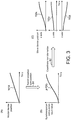
- a position (X-axis position) 101X of the master device 101 increases linearly with the lapse of time, as shown in (A) of FIG. 3 .
- the display scale of the time axis (horizontal axis) is considerably larger than the period t in (A) to (C) of FIG. 3 , a step-like change in the graph for each period t is not shown.
- the synchronization computation S1 requires a considerable amount of calculations if the predetermined corresponding relation is a computation according to a curve (the aforementioned cam curve in this example), this is not a problem when number m of axes of the master device 101 is less than the number n of axes of the slave device 102 (in the case of m ⁇ n) because the number m of axes is relatively small.
- the coordinate transformation unit 32 illustrated in Fig. 1 performs coordinate transformation (which is represented by a sign S2) from the XYZ coordinate system of the master device 101 into the xyz coordinate system of the slave device 102 for the synchronization computation result value p obtained according to the synchronization computation S1.
- the x, y and z components are obtained as represented by curves 102x, 102y and 102z in (C) of FIG. 3 .
- These curves 102x, 102y and 102z represent positions to be taken by the x axis, y axis and z axis of the slave device 102.
- changes in the synchronization computation result value p may correspond to a vector parallel to any of the xy plane, yz plane and zx plane in the xyz coordinate system of the slave device 102 or correspond to a vector parallel to any of the x axis, y axis and z axis.
- one or two of the coefficients K x , K y and K z become zero.
- the slave device command value computing unit 40 receives signals representing the x, y and z components from the coordinate transformation unit 32 and updates the command value CVn for each axis of the slave device 102.
- the amount of calculations can be reduced in the process of obtaining the command value CVn for each axis of the slave device 102 from the command value CVm for each axis (or the measured current value CVm' of each axis) of the master device 101 according to the control device 10.
- the above-described control device 10 can be substantially configured using a computer device (e.g., a programmable logic controller (PLC) or the like). Accordingly, it is desirable to configure the control method (the process of performing the synchronization computation S1 and then performing the coordinate transformation S2) described as the operation of the central computing unit 30 as a program executed by a computer. In addition, it is desirable to record such a program in a computer-readable non-transitory recording medium. In such a case, it is possible to implement the above-described control method by causing a computer device to read and execute such a program recorded in a recording medium.
- PLC programmable logic controller
- the master device 101 is a 1-axis conveyor belt and the slave device 102 is a 6-axis robot.
- the present invention is not limited thereto.
- devices having various numbers m and n of axes such as a 1-axis device like a conveyor belt, a 2-axis device like an X-Y table, a 4-axis device like a 4-axis parallel link robot, a 5-axis device like a 5-axis horizontal articulated robot, and a 6-axis device like a 6-axis articulated robot, can be objects for a master device and a slave device.
- the present invention is applied in cases in which the number m of axes of a master device is less than the number n of axes of a slave device.
Landscapes
- Engineering & Computer Science (AREA)
- General Physics & Mathematics (AREA)
- Automation & Control Theory (AREA)
- Physics & Mathematics (AREA)
- Robotics (AREA)
- Mechanical Engineering (AREA)
- Manufacturing & Machinery (AREA)
- General Engineering & Computer Science (AREA)
- Quality & Reliability (AREA)
- Human Computer Interaction (AREA)
- Computing Systems (AREA)
- Theoretical Computer Science (AREA)
- Numerical Control (AREA)
- Manipulator (AREA)
Claims (3)
- Dispositif de commande pour synchroniser et commander un dispositif maître (101) et un dispositif esclave (102) à une période fixe lorsqu'un nombre d'axes du dispositif maître (101) est inférieur à un nombre d'axes du dispositif esclave (102), comprenant :une unité de calcul (30) configurée pour obtenir une valeur de commande (CVn) pour chaque axe du dispositif esclave (102) par un calcul à la période fixe sur la base d'une valeur de commande (CVm) pour chaque axe ou une valeur courante mesurée (CVm') de chaque axe du dispositif maître (101),dans lequel l'unité de calcul (30) comprend :
une unité de calcul de synchronisation (31) configurée pour réaliser un calcul de synchronisation afin de maintenir une position du dispositif maître (101) et une position du dispositif esclave (102) dans une relation correspondante prédéterminée pour la valeur de commande (CVm) pour chaque axe ou la valeur courante mesurée (CVm') de chaque axe du dispositif maître (101) à la période fixe ; le dispositif de commande étant caractérisé en ce qu'il comprend en outre :
une unité de transformation de coordonnées (32) configurée pour réaliser une transformation de coordonnées depuis un système de coordonnées du dispositif maître (101) dans un système de coordonnées du dispositif esclave (102) pour des valeurs de résultat de calcul de synchronisation obtenues par le calcul de synchronisation. - Procédé de commande pour obtenir une valeur de commande (CVn) pour chaque axe d'un dispositif esclave (102) par un calcul à une période fixe sur la base d'une valeur de commande (CVm) pour chaque axe ou une valeur courante mesurée (CVm') de chaque axe d'un dispositif maître (101), et pour synchroniser et commander le dispositif maître (101) et le dispositif esclave (102) lorsque le nombre d'axes du dispositif maître (101) est inférieur au nombre d'axes du dispositif esclave (102), comprenant :
la réalisation d'un calcul de synchronisation pour maintenir une position du dispositif maître (101) et une position du dispositif esclave (102) dans une relation correspondante prédéterminée pour la valeur de commande (CVm) pour chaque axe ou la valeur courante mesurée (CVm') de chaque axe du dispositif maître (101) à la période fixe ; le procédé de commande étant caractérisé en ce qu'il comprend en outre :
la réalisation d'une transformation de coordonnées depuis un système de coordonnées du dispositif maître (101) dans un système de coordonnées du dispositif esclave (102) pour des valeurs de résultat de calcul de synchronisation obtenues par le calcul de synchronisation. - Programme qui, lorsqu'il est exécuté par un ordinateur, amène l'ordinateur à exécuter le procédé de commande selon la revendication 2.
Applications Claiming Priority (1)
| Application Number | Priority Date | Filing Date | Title |
|---|---|---|---|
| JP2018044531A JP6954192B2 (ja) | 2018-03-12 | 2018-03-12 | 制御装置、制御方法、およびプログラム |
Publications (2)
| Publication Number | Publication Date |
|---|---|
| EP3540541A1 EP3540541A1 (fr) | 2019-09-18 |
| EP3540541B1 true EP3540541B1 (fr) | 2021-02-17 |
Family
ID=65019325
Family Applications (1)
| Application Number | Title | Priority Date | Filing Date |
|---|---|---|---|
| EP19151156.7A Not-in-force EP3540541B1 (fr) | 2018-03-12 | 2019-01-10 | Procédé, dispositif et programme de commande |
Country Status (4)
| Country | Link |
|---|---|
| US (1) | US20190275665A1 (fr) |
| EP (1) | EP3540541B1 (fr) |
| JP (1) | JP6954192B2 (fr) |
| CN (1) | CN110262291B (fr) |
Families Citing this family (2)
| Publication number | Priority date | Publication date | Assignee | Title |
|---|---|---|---|---|
| CN113118939A (zh) * | 2021-04-05 | 2021-07-16 | 吉林市佰丰科技有限公司 | 一种智能化高效的打磨抓取一体式机器人加工机构 |
| WO2022259387A1 (fr) * | 2021-06-08 | 2022-12-15 | ファナック株式会社 | Système de production |
Family Cites Families (19)
| Publication number | Priority date | Publication date | Assignee | Title |
|---|---|---|---|---|
| JPH0649260B2 (ja) * | 1989-02-28 | 1994-06-29 | 豊田工機株式会社 | 同期制御装置 |
| JPH03142180A (ja) * | 1989-10-25 | 1991-06-17 | Toshiba Corp | 異構造マスタスレーブマニピュレータの制御装置 |
| JPH06138920A (ja) | 1992-10-27 | 1994-05-20 | Yokogawa Electric Corp | モーションコントローラ |
| JP2002192486A (ja) * | 2000-12-25 | 2002-07-10 | Seiko Epson Corp | ロボット制御方法及び該方法を適用したロボットコントローラ |
| JP2004130444A (ja) * | 2002-10-10 | 2004-04-30 | Fanuc Ltd | 同期制御装置 |
| JP4468216B2 (ja) * | 2005-03-14 | 2010-05-26 | 三菱電機株式会社 | 同期制御装置 |
| EP2144127B1 (fr) * | 2008-07-08 | 2014-04-30 | Siemens Aktiengesellschaft | Procédé et appareil de commande pour la synchronisation d'un récepteur d'un appareil de manipulation |
| JP5098863B2 (ja) * | 2008-07-11 | 2012-12-12 | 株式会社安川電機 | 同期制御装置 |
| JP4853842B2 (ja) * | 2010-01-12 | 2012-01-11 | 株式会社安川電機 | 同期制御装置 |
| CN102540965A (zh) * | 2010-12-09 | 2012-07-04 | 沈阳高精数控技术有限公司 | 总线式伺服双轴同步控制方法 |
| CN102298357B (zh) * | 2011-03-28 | 2012-09-19 | 中国科学院沈阳计算技术研究所有限公司 | 基于现场总线的cnc双轴协调式同步控制方法 |
| JP5803337B2 (ja) * | 2011-06-28 | 2015-11-04 | オムロン株式会社 | 同期制御装置、同期制御方法、同期制御プログラム、および同期制御プログラムを記録したコンピュータ読み取り可能な記録媒体 |
| JP5314110B2 (ja) * | 2011-11-25 | 2013-10-16 | ファナック株式会社 | マスタ軸とスレーブ軸との同期制御を行うモータ制御装置 |
| JP5642828B2 (ja) * | 2013-03-28 | 2014-12-17 | ファナック株式会社 | 二つの軸を互いに同期させる同期制御装置 |
| CN105938324B (zh) * | 2015-03-04 | 2019-07-16 | 欧姆龙株式会社 | 控制装置及同步控制方法 |
| JP6333782B2 (ja) * | 2015-08-03 | 2018-05-30 | ファナック株式会社 | 同期開始ブロックのショックを解消する機能を有する同期制御装置 |
| JP2017162156A (ja) * | 2016-03-09 | 2017-09-14 | パナソニック デバイスSunx株式会社 | モーションコントローラ、同期制御方法 |
| JP6594813B2 (ja) * | 2016-03-24 | 2019-10-23 | 株式会社神戸製鋼所 | 通信制御システム及び通信制御方法 |
| JP6441257B2 (ja) * | 2016-04-28 | 2018-12-19 | ファナック株式会社 | 数値制御装置および同期追従制御方法 |
-
2018
- 2018-03-12 JP JP2018044531A patent/JP6954192B2/ja active Active
-
2019
- 2019-01-10 EP EP19151156.7A patent/EP3540541B1/fr not_active Not-in-force
- 2019-01-10 CN CN201910022180.6A patent/CN110262291B/zh not_active Expired - Fee Related
- 2019-01-18 US US16/251,094 patent/US20190275665A1/en not_active Abandoned
Non-Patent Citations (1)
| Title |
|---|
| None * |
Also Published As
| Publication number | Publication date |
|---|---|
| JP6954192B2 (ja) | 2021-10-27 |
| JP2019155521A (ja) | 2019-09-19 |
| EP3540541A1 (fr) | 2019-09-18 |
| CN110262291B (zh) | 2022-04-19 |
| US20190275665A1 (en) | 2019-09-12 |
| CN110262291A (zh) | 2019-09-20 |
Similar Documents
| Publication | Publication Date | Title |
|---|---|---|
| EP3540537B1 (fr) | Procédé, dispositif et programme de commande | |
| CN111026164B (zh) | 一种机器人目标跟踪轨迹规划方法 | |
| US10864632B2 (en) | Direct teaching method of robot | |
| US10481580B2 (en) | Trajectory control device | |
| US20180264649A1 (en) | Controller, control system, and control method | |
| EP3542969A1 (fr) | Procédé de correction de position de travail et robot de travail | |
| US20140074299A1 (en) | Themal dispalcement compensating device of machine tool | |
| JP2002018754A (ja) | ロボット装置及びその制御方法 | |
| US10710242B2 (en) | Controller, control system, and control method | |
| US20180126554A1 (en) | Method for motion simulation of a manipulator | |
| CN110253582B (zh) | 一种流水线上机械手移动对位的方法 | |
| EP3542973A1 (fr) | Robot de travail et procédé de correction de position de travail | |
| US12304078B2 (en) | Robot control system, control program, and control method | |
| EP3540541B1 (fr) | Procédé, dispositif et programme de commande | |
| CN111993410B (zh) | 控制装置、机械系统以及时刻同步方法 | |
| JPH1133960A (ja) | ロボット制御方法 | |
| JP4226629B2 (ja) | 複数の軸を制御する数値制御装置及び数値制御装置を用いた同期制御方法 | |
| Woodside et al. | A feedforward kinematic error controller with an angular positioning deviations model for backlash compensation of industrial robots | |
| JP2005118995A (ja) | ロボットの制御方法および制御装置 | |
| EP0310996B1 (fr) | Méthode et dispositif pour générer et appliquer des données d'apprentissage communes de robots | |
| JPS599708A (ja) | ロボツトシステムの動作誤差補正方法 | |
| KR0161010B1 (ko) | 공구직경에 따른 이동경로 보정방법 | |
| JP4281872B2 (ja) | ロボット制御装置 | |
| JPS629407A (ja) | マニピユレ−タ制御装置 | |
| JPH0315908A (ja) | 移動部材の軌跡方向の加減速方法 |
Legal Events
| Date | Code | Title | Description |
|---|---|---|---|
| PUAI | Public reference made under article 153(3) epc to a published international application that has entered the european phase |
Free format text: ORIGINAL CODE: 0009012 |
|
| STAA | Information on the status of an ep patent application or granted ep patent |
Free format text: STATUS: REQUEST FOR EXAMINATION WAS MADE |
|
| 17P | Request for examination filed |
Effective date: 20190110 |
|
| AK | Designated contracting states |
Kind code of ref document: A1 Designated state(s): AL AT BE BG CH CY CZ DE DK EE ES FI FR GB GR HR HU IE IS IT LI LT LU LV MC MK MT NL NO PL PT RO RS SE SI SK SM TR |
|
| AX | Request for extension of the european patent |
Extension state: BA ME |
|
| RBV | Designated contracting states (corrected) |
Designated state(s): AL AT BE BG CH CY CZ DE DK EE ES FI FR GB GR HR HU IE IS IT LI LT LU LV MC MK MT NL NO PL PT RO RS SE SI SK SM TR |
|
| GRAP | Despatch of communication of intention to grant a patent |
Free format text: ORIGINAL CODE: EPIDOSNIGR1 |
|
| STAA | Information on the status of an ep patent application or granted ep patent |
Free format text: STATUS: GRANT OF PATENT IS INTENDED |
|
| INTG | Intention to grant announced |
Effective date: 20200819 |
|
| GRAS | Grant fee paid |
Free format text: ORIGINAL CODE: EPIDOSNIGR3 |
|
| GRAA | (expected) grant |
Free format text: ORIGINAL CODE: 0009210 |
|
| STAA | Information on the status of an ep patent application or granted ep patent |
Free format text: STATUS: THE PATENT HAS BEEN GRANTED |
|
| AK | Designated contracting states |
Kind code of ref document: B1 Designated state(s): AL AT BE BG CH CY CZ DE DK EE ES FI FR GB GR HR HU IE IS IT LI LT LU LV MC MK MT NL NO PL PT RO RS SE SI SK SM TR |
|
| REG | Reference to a national code |
Ref country code: GB Ref legal event code: FG4D |
|
| REG | Reference to a national code |
Ref country code: CH Ref legal event code: EP |
|
| REG | Reference to a national code |
Ref country code: DE Ref legal event code: R096 Ref document number: 602019002423 Country of ref document: DE |
|
| REG | Reference to a national code |
Ref country code: AT Ref legal event code: REF Ref document number: 1362275 Country of ref document: AT Kind code of ref document: T Effective date: 20210315 |
|
| REG | Reference to a national code |
Ref country code: IE Ref legal event code: FG4D |
|
| REG | Reference to a national code |
Ref country code: LT Ref legal event code: MG9D |
|
| REG | Reference to a national code |
Ref country code: NL Ref legal event code: MP Effective date: 20210217 |
|
| PG25 | Lapsed in a contracting state [announced via postgrant information from national office to epo] |
Ref country code: FI Free format text: LAPSE BECAUSE OF FAILURE TO SUBMIT A TRANSLATION OF THE DESCRIPTION OR TO PAY THE FEE WITHIN THE PRESCRIBED TIME-LIMIT Effective date: 20210217 Ref country code: GR Free format text: LAPSE BECAUSE OF FAILURE TO SUBMIT A TRANSLATION OF THE DESCRIPTION OR TO PAY THE FEE WITHIN THE PRESCRIBED TIME-LIMIT Effective date: 20210518 Ref country code: HR Free format text: LAPSE BECAUSE OF FAILURE TO SUBMIT A TRANSLATION OF THE DESCRIPTION OR TO PAY THE FEE WITHIN THE PRESCRIBED TIME-LIMIT Effective date: 20210217 Ref country code: BG Free format text: LAPSE BECAUSE OF FAILURE TO SUBMIT A TRANSLATION OF THE DESCRIPTION OR TO PAY THE FEE WITHIN THE PRESCRIBED TIME-LIMIT Effective date: 20210517 Ref country code: NO Free format text: LAPSE BECAUSE OF FAILURE TO SUBMIT A TRANSLATION OF THE DESCRIPTION OR TO PAY THE FEE WITHIN THE PRESCRIBED TIME-LIMIT Effective date: 20210517 Ref country code: PT Free format text: LAPSE BECAUSE OF FAILURE TO SUBMIT A TRANSLATION OF THE DESCRIPTION OR TO PAY THE FEE WITHIN THE PRESCRIBED TIME-LIMIT Effective date: 20210617 Ref country code: LT Free format text: LAPSE BECAUSE OF FAILURE TO SUBMIT A TRANSLATION OF THE DESCRIPTION OR TO PAY THE FEE WITHIN THE PRESCRIBED TIME-LIMIT Effective date: 20210217 |
|
| REG | Reference to a national code |
Ref country code: AT Ref legal event code: MK05 Ref document number: 1362275 Country of ref document: AT Kind code of ref document: T Effective date: 20210217 |
|
| PG25 | Lapsed in a contracting state [announced via postgrant information from national office to epo] |
Ref country code: LV Free format text: LAPSE BECAUSE OF FAILURE TO SUBMIT A TRANSLATION OF THE DESCRIPTION OR TO PAY THE FEE WITHIN THE PRESCRIBED TIME-LIMIT Effective date: 20210217 Ref country code: RS Free format text: LAPSE BECAUSE OF FAILURE TO SUBMIT A TRANSLATION OF THE DESCRIPTION OR TO PAY THE FEE WITHIN THE PRESCRIBED TIME-LIMIT Effective date: 20210217 Ref country code: PL Free format text: LAPSE BECAUSE OF FAILURE TO SUBMIT A TRANSLATION OF THE DESCRIPTION OR TO PAY THE FEE WITHIN THE PRESCRIBED TIME-LIMIT Effective date: 20210217 Ref country code: NL Free format text: LAPSE BECAUSE OF FAILURE TO SUBMIT A TRANSLATION OF THE DESCRIPTION OR TO PAY THE FEE WITHIN THE PRESCRIBED TIME-LIMIT Effective date: 20210217 Ref country code: SE Free format text: LAPSE BECAUSE OF FAILURE TO SUBMIT A TRANSLATION OF THE DESCRIPTION OR TO PAY THE FEE WITHIN THE PRESCRIBED TIME-LIMIT Effective date: 20210217 |
|
| PG25 | Lapsed in a contracting state [announced via postgrant information from national office to epo] |
Ref country code: IS Free format text: LAPSE BECAUSE OF FAILURE TO SUBMIT A TRANSLATION OF THE DESCRIPTION OR TO PAY THE FEE WITHIN THE PRESCRIBED TIME-LIMIT Effective date: 20210617 |
|
| PG25 | Lapsed in a contracting state [announced via postgrant information from national office to epo] |
Ref country code: AT Free format text: LAPSE BECAUSE OF FAILURE TO SUBMIT A TRANSLATION OF THE DESCRIPTION OR TO PAY THE FEE WITHIN THE PRESCRIBED TIME-LIMIT Effective date: 20210217 Ref country code: SM Free format text: LAPSE BECAUSE OF FAILURE TO SUBMIT A TRANSLATION OF THE DESCRIPTION OR TO PAY THE FEE WITHIN THE PRESCRIBED TIME-LIMIT Effective date: 20210217 Ref country code: CZ Free format text: LAPSE BECAUSE OF FAILURE TO SUBMIT A TRANSLATION OF THE DESCRIPTION OR TO PAY THE FEE WITHIN THE PRESCRIBED TIME-LIMIT Effective date: 20210217 Ref country code: EE Free format text: LAPSE BECAUSE OF FAILURE TO SUBMIT A TRANSLATION OF THE DESCRIPTION OR TO PAY THE FEE WITHIN THE PRESCRIBED TIME-LIMIT Effective date: 20210217 |
|
| REG | Reference to a national code |
Ref country code: DE Ref legal event code: R097 Ref document number: 602019002423 Country of ref document: DE |
|
| PG25 | Lapsed in a contracting state [announced via postgrant information from national office to epo] |
Ref country code: DK Free format text: LAPSE BECAUSE OF FAILURE TO SUBMIT A TRANSLATION OF THE DESCRIPTION OR TO PAY THE FEE WITHIN THE PRESCRIBED TIME-LIMIT Effective date: 20210217 Ref country code: RO Free format text: LAPSE BECAUSE OF FAILURE TO SUBMIT A TRANSLATION OF THE DESCRIPTION OR TO PAY THE FEE WITHIN THE PRESCRIBED TIME-LIMIT Effective date: 20210217 Ref country code: SK Free format text: LAPSE BECAUSE OF FAILURE TO SUBMIT A TRANSLATION OF THE DESCRIPTION OR TO PAY THE FEE WITHIN THE PRESCRIBED TIME-LIMIT Effective date: 20210217 |
|
| PLBE | No opposition filed within time limit |
Free format text: ORIGINAL CODE: 0009261 |
|
| STAA | Information on the status of an ep patent application or granted ep patent |
Free format text: STATUS: NO OPPOSITION FILED WITHIN TIME LIMIT |
|
| 26N | No opposition filed |
Effective date: 20211118 |
|
| PG25 | Lapsed in a contracting state [announced via postgrant information from national office to epo] |
Ref country code: AL Free format text: LAPSE BECAUSE OF FAILURE TO SUBMIT A TRANSLATION OF THE DESCRIPTION OR TO PAY THE FEE WITHIN THE PRESCRIBED TIME-LIMIT Effective date: 20210217 Ref country code: ES Free format text: LAPSE BECAUSE OF FAILURE TO SUBMIT A TRANSLATION OF THE DESCRIPTION OR TO PAY THE FEE WITHIN THE PRESCRIBED TIME-LIMIT Effective date: 20210217 |
|
| PG25 | Lapsed in a contracting state [announced via postgrant information from national office to epo] |
Ref country code: SI Free format text: LAPSE BECAUSE OF FAILURE TO SUBMIT A TRANSLATION OF THE DESCRIPTION OR TO PAY THE FEE WITHIN THE PRESCRIBED TIME-LIMIT Effective date: 20210217 |
|
| PG25 | Lapsed in a contracting state [announced via postgrant information from national office to epo] |
Ref country code: IT Free format text: LAPSE BECAUSE OF FAILURE TO SUBMIT A TRANSLATION OF THE DESCRIPTION OR TO PAY THE FEE WITHIN THE PRESCRIBED TIME-LIMIT Effective date: 20210217 |
|
| PG25 | Lapsed in a contracting state [announced via postgrant information from national office to epo] |
Ref country code: IS Free format text: LAPSE BECAUSE OF FAILURE TO SUBMIT A TRANSLATION OF THE DESCRIPTION OR TO PAY THE FEE WITHIN THE PRESCRIBED TIME-LIMIT Effective date: 20210617 |
|
| PG25 | Lapsed in a contracting state [announced via postgrant information from national office to epo] |
Ref country code: MC Free format text: LAPSE BECAUSE OF FAILURE TO SUBMIT A TRANSLATION OF THE DESCRIPTION OR TO PAY THE FEE WITHIN THE PRESCRIBED TIME-LIMIT Effective date: 20210217 |
|
| REG | Reference to a national code |
Ref country code: CH Ref legal event code: PL |
|
| REG | Reference to a national code |
Ref country code: BE Ref legal event code: MM Effective date: 20220131 |
|
| PG25 | Lapsed in a contracting state [announced via postgrant information from national office to epo] |
Ref country code: LU Free format text: LAPSE BECAUSE OF NON-PAYMENT OF DUE FEES Effective date: 20220110 |
|
| PG25 | Lapsed in a contracting state [announced via postgrant information from national office to epo] |
Ref country code: FR Free format text: LAPSE BECAUSE OF NON-PAYMENT OF DUE FEES Effective date: 20220131 Ref country code: BE Free format text: LAPSE BECAUSE OF NON-PAYMENT OF DUE FEES Effective date: 20220131 |
|
| PG25 | Lapsed in a contracting state [announced via postgrant information from national office to epo] |
Ref country code: LI Free format text: LAPSE BECAUSE OF NON-PAYMENT OF DUE FEES Effective date: 20220131 Ref country code: CH Free format text: LAPSE BECAUSE OF NON-PAYMENT OF DUE FEES Effective date: 20220131 |
|
| PG25 | Lapsed in a contracting state [announced via postgrant information from national office to epo] |
Ref country code: IE Free format text: LAPSE BECAUSE OF NON-PAYMENT OF DUE FEES Effective date: 20220110 |
|
| GBPC | Gb: european patent ceased through non-payment of renewal fee |
Effective date: 20230110 |
|
| PG25 | Lapsed in a contracting state [announced via postgrant information from national office to epo] |
Ref country code: GB Free format text: LAPSE BECAUSE OF NON-PAYMENT OF DUE FEES Effective date: 20230110 |
|
| PG25 | Lapsed in a contracting state [announced via postgrant information from national office to epo] |
Ref country code: MK Free format text: LAPSE BECAUSE OF FAILURE TO SUBMIT A TRANSLATION OF THE DESCRIPTION OR TO PAY THE FEE WITHIN THE PRESCRIBED TIME-LIMIT Effective date: 20210217 Ref country code: CY Free format text: LAPSE BECAUSE OF FAILURE TO SUBMIT A TRANSLATION OF THE DESCRIPTION OR TO PAY THE FEE WITHIN THE PRESCRIBED TIME-LIMIT Effective date: 20210217 |
|
| PGFP | Annual fee paid to national office [announced via postgrant information from national office to epo] |
Ref country code: DE Payment date: 20240119 Year of fee payment: 6 |
|
| PG25 | Lapsed in a contracting state [announced via postgrant information from national office to epo] |
Ref country code: HU Free format text: LAPSE BECAUSE OF FAILURE TO SUBMIT A TRANSLATION OF THE DESCRIPTION OR TO PAY THE FEE WITHIN THE PRESCRIBED TIME-LIMIT; INVALID AB INITIO Effective date: 20190110 |
|
| PG25 | Lapsed in a contracting state [announced via postgrant information from national office to epo] |
Ref country code: TR Free format text: LAPSE BECAUSE OF FAILURE TO SUBMIT A TRANSLATION OF THE DESCRIPTION OR TO PAY THE FEE WITHIN THE PRESCRIBED TIME-LIMIT Effective date: 20210217 |
|
| PG25 | Lapsed in a contracting state [announced via postgrant information from national office to epo] |
Ref country code: MT Free format text: LAPSE BECAUSE OF FAILURE TO SUBMIT A TRANSLATION OF THE DESCRIPTION OR TO PAY THE FEE WITHIN THE PRESCRIBED TIME-LIMIT Effective date: 20210217 |
|
| REG | Reference to a national code |
Ref country code: DE Ref legal event code: R119 Ref document number: 602019002423 Country of ref document: DE |
|
| PG25 | Lapsed in a contracting state [announced via postgrant information from national office to epo] |
Ref country code: DE Free format text: LAPSE BECAUSE OF NON-PAYMENT OF DUE FEES Effective date: 20250801 |