EP3540636A1 - Verfahren zur unterscheidung eines realen dreidimensionalen objektes von einer zweidimensionalen simulation des realen objektes - Google Patents
Verfahren zur unterscheidung eines realen dreidimensionalen objektes von einer zweidimensionalen simulation des realen objektes Download PDFInfo
- Publication number
- EP3540636A1 EP3540636A1 EP18382295.6A EP18382295A EP3540636A1 EP 3540636 A1 EP3540636 A1 EP 3540636A1 EP 18382295 A EP18382295 A EP 18382295A EP 3540636 A1 EP3540636 A1 EP 3540636A1
- Authority
- EP
- European Patent Office
- Prior art keywords
- image
- matrix
- neural network
- spoof
- output
- Prior art date
- Legal status (The legal status is an assumption and is not a legal conclusion. Google has not performed a legal analysis and makes no representation as to the accuracy of the status listed.)
- Ceased
Links
Images


Classifications
-
- G—PHYSICS
- G06—COMPUTING OR CALCULATING; COUNTING
- G06V—IMAGE OR VIDEO RECOGNITION OR UNDERSTANDING
- G06V40/00—Recognition of biometric, human-related or animal-related patterns in image or video data
- G06V40/10—Human or animal bodies, e.g. vehicle occupants or pedestrians; Body parts, e.g. hands
- G06V40/12—Fingerprints or palmprints
- G06V40/13—Sensors therefor
- G06V40/1312—Sensors therefor direct reading, e.g. contactless acquisition
-
- G—PHYSICS
- G06—COMPUTING OR CALCULATING; COUNTING
- G06F—ELECTRIC DIGITAL DATA PROCESSING
- G06F18/00—Pattern recognition
- G06F18/20—Analysing
- G06F18/21—Design or setup of recognition systems or techniques; Extraction of features in feature space; Blind source separation
-
- G—PHYSICS
- G06—COMPUTING OR CALCULATING; COUNTING
- G06N—COMPUTING ARRANGEMENTS BASED ON SPECIFIC COMPUTATIONAL MODELS
- G06N3/00—Computing arrangements based on biological models
- G06N3/02—Neural networks
- G06N3/04—Architecture, e.g. interconnection topology
- G06N3/0464—Convolutional networks [CNN, ConvNet]
-
- G—PHYSICS
- G06—COMPUTING OR CALCULATING; COUNTING
- G06N—COMPUTING ARRANGEMENTS BASED ON SPECIFIC COMPUTATIONAL MODELS
- G06N3/00—Computing arrangements based on biological models
- G06N3/02—Neural networks
- G06N3/08—Learning methods
-
- G—PHYSICS
- G06—COMPUTING OR CALCULATING; COUNTING
- G06N—COMPUTING ARRANGEMENTS BASED ON SPECIFIC COMPUTATIONAL MODELS
- G06N3/00—Computing arrangements based on biological models
- G06N3/02—Neural networks
- G06N3/08—Learning methods
- G06N3/09—Supervised learning
-
- G—PHYSICS
- G06—COMPUTING OR CALCULATING; COUNTING
- G06T—IMAGE DATA PROCESSING OR GENERATION, IN GENERAL
- G06T7/00—Image analysis
- G06T7/70—Determining position or orientation of objects or cameras
-
- G—PHYSICS
- G06—COMPUTING OR CALCULATING; COUNTING
- G06T—IMAGE DATA PROCESSING OR GENERATION, IN GENERAL
- G06T7/00—Image analysis
- G06T7/90—Determination of colour characteristics
-
- G—PHYSICS
- G06—COMPUTING OR CALCULATING; COUNTING
- G06V—IMAGE OR VIDEO RECOGNITION OR UNDERSTANDING
- G06V10/00—Arrangements for image or video recognition or understanding
- G06V10/10—Image acquisition
- G06V10/17—Image acquisition using hand-held instruments
-
- G—PHYSICS
- G06—COMPUTING OR CALCULATING; COUNTING
- G06V—IMAGE OR VIDEO RECOGNITION OR UNDERSTANDING
- G06V10/00—Arrangements for image or video recognition or understanding
- G06V10/20—Image preprocessing
- G06V10/255—Detecting or recognising potential candidate objects based on visual cues, e.g. shapes
-
- G—PHYSICS
- G06—COMPUTING OR CALCULATING; COUNTING
- G06V—IMAGE OR VIDEO RECOGNITION OR UNDERSTANDING
- G06V10/00—Arrangements for image or video recognition or understanding
- G06V10/40—Extraction of image or video features
- G06V10/44—Local feature extraction by analysis of parts of the pattern, e.g. by detecting edges, contours, loops, corners, strokes or intersections; Connectivity analysis, e.g. of connected components
- G06V10/443—Local feature extraction by analysis of parts of the pattern, e.g. by detecting edges, contours, loops, corners, strokes or intersections; Connectivity analysis, e.g. of connected components by matching or filtering
- G06V10/449—Biologically inspired filters, e.g. difference of Gaussians [DoG] or Gabor filters
- G06V10/451—Biologically inspired filters, e.g. difference of Gaussians [DoG] or Gabor filters with interaction between the filter responses, e.g. cortical complex cells
- G06V10/454—Integrating the filters into a hierarchical structure, e.g. convolutional neural networks [CNN]
-
- G—PHYSICS
- G06—COMPUTING OR CALCULATING; COUNTING
- G06V—IMAGE OR VIDEO RECOGNITION OR UNDERSTANDING
- G06V10/00—Arrangements for image or video recognition or understanding
- G06V10/70—Arrangements for image or video recognition or understanding using pattern recognition or machine learning
- G06V10/74—Image or video pattern matching; Proximity measures in feature spaces
- G06V10/75—Organisation of the matching processes, e.g. simultaneous or sequential comparisons of image or video features; Coarse-fine approaches, e.g. multi-scale approaches; using context analysis; Selection of dictionaries
- G06V10/751—Comparing pixel values or logical combinations thereof, or feature values having positional relevance, e.g. template matching
-
- G—PHYSICS
- G06—COMPUTING OR CALCULATING; COUNTING
- G06V—IMAGE OR VIDEO RECOGNITION OR UNDERSTANDING
- G06V10/00—Arrangements for image or video recognition or understanding
- G06V10/70—Arrangements for image or video recognition or understanding using pattern recognition or machine learning
- G06V10/82—Arrangements for image or video recognition or understanding using pattern recognition or machine learning using neural networks
-
- G—PHYSICS
- G06—COMPUTING OR CALCULATING; COUNTING
- G06V—IMAGE OR VIDEO RECOGNITION OR UNDERSTANDING
- G06V20/00—Scenes; Scene-specific elements
- G06V20/60—Type of objects
- G06V20/64—Three-dimensional [3D] objects
-
- G—PHYSICS
- G06—COMPUTING OR CALCULATING; COUNTING
- G06V—IMAGE OR VIDEO RECOGNITION OR UNDERSTANDING
- G06V30/00—Character recognition; Recognising digital ink; Document-oriented image-based pattern recognition
- G06V30/10—Character recognition
- G06V30/14—Image acquisition
- G06V30/142—Image acquisition using hand-held instruments; Constructional details of the instruments
-
- G—PHYSICS
- G06—COMPUTING OR CALCULATING; COUNTING
- G06V—IMAGE OR VIDEO RECOGNITION OR UNDERSTANDING
- G06V40/00—Recognition of biometric, human-related or animal-related patterns in image or video data
- G06V40/10—Human or animal bodies, e.g. vehicle occupants or pedestrians; Body parts, e.g. hands
- G06V40/107—Static hand or arm
-
- G—PHYSICS
- G06—COMPUTING OR CALCULATING; COUNTING
- G06V—IMAGE OR VIDEO RECOGNITION OR UNDERSTANDING
- G06V40/00—Recognition of biometric, human-related or animal-related patterns in image or video data
- G06V40/10—Human or animal bodies, e.g. vehicle occupants or pedestrians; Body parts, e.g. hands
- G06V40/12—Fingerprints or palmprints
- G06V40/13—Sensors therefor
- G06V40/1318—Sensors therefor using electro-optical elements or layers, e.g. electroluminescent sensing
-
- G—PHYSICS
- G06—COMPUTING OR CALCULATING; COUNTING
- G06V—IMAGE OR VIDEO RECOGNITION OR UNDERSTANDING
- G06V40/00—Recognition of biometric, human-related or animal-related patterns in image or video data
- G06V40/10—Human or animal bodies, e.g. vehicle occupants or pedestrians; Body parts, e.g. hands
- G06V40/12—Fingerprints or palmprints
- G06V40/1347—Preprocessing; Feature extraction
-
- G—PHYSICS
- G06—COMPUTING OR CALCULATING; COUNTING
- G06V—IMAGE OR VIDEO RECOGNITION OR UNDERSTANDING
- G06V40/00—Recognition of biometric, human-related or animal-related patterns in image or video data
- G06V40/10—Human or animal bodies, e.g. vehicle occupants or pedestrians; Body parts, e.g. hands
- G06V40/12—Fingerprints or palmprints
- G06V40/1365—Matching; Classification
-
- G—PHYSICS
- G06—COMPUTING OR CALCULATING; COUNTING
- G06V—IMAGE OR VIDEO RECOGNITION OR UNDERSTANDING
- G06V40/00—Recognition of biometric, human-related or animal-related patterns in image or video data
- G06V40/10—Human or animal bodies, e.g. vehicle occupants or pedestrians; Body parts, e.g. hands
- G06V40/12—Fingerprints or palmprints
- G06V40/1382—Detecting the live character of the finger, i.e. distinguishing from a fake or cadaver finger
- G06V40/1388—Detecting the live character of the finger, i.e. distinguishing from a fake or cadaver finger using image processing
-
- G—PHYSICS
- G06—COMPUTING OR CALCULATING; COUNTING
- G06V—IMAGE OR VIDEO RECOGNITION OR UNDERSTANDING
- G06V40/00—Recognition of biometric, human-related or animal-related patterns in image or video data
- G06V40/40—Spoof detection, e.g. liveness detection
-
- H—ELECTRICITY
- H04—ELECTRIC COMMUNICATION TECHNIQUE
- H04N—PICTORIAL COMMUNICATION, e.g. TELEVISION
- H04N23/00—Cameras or camera modules comprising electronic image sensors; Control thereof
- H04N23/56—Cameras or camera modules comprising electronic image sensors; Control thereof provided with illuminating means
-
- G—PHYSICS
- G06—COMPUTING OR CALCULATING; COUNTING
- G06T—IMAGE DATA PROCESSING OR GENERATION, IN GENERAL
- G06T2207/00—Indexing scheme for image analysis or image enhancement
- G06T2207/20—Special algorithmic details
- G06T2207/20021—Dividing image into blocks, subimages or windows
-
- G—PHYSICS
- G06—COMPUTING OR CALCULATING; COUNTING
- G06T—IMAGE DATA PROCESSING OR GENERATION, IN GENERAL
- G06T2207/00—Indexing scheme for image analysis or image enhancement
- G06T2207/20—Special algorithmic details
- G06T2207/20084—Artificial neural networks [ANN]
-
- G—PHYSICS
- G06—COMPUTING OR CALCULATING; COUNTING
- G06T—IMAGE DATA PROCESSING OR GENERATION, IN GENERAL
- G06T2207/00—Indexing scheme for image analysis or image enhancement
- G06T2207/30—Subject of image; Context of image processing
- G06T2207/30196—Human being; Person
Definitions
- the present invention relates to a computer implemented method for distinguishing a real three-dimensional object, like a finger of a hand, from a two-dimensional spoof of the real object according to claim 1, and a mobile device implementing this method according to claim 15.
- AlexNet as presented, for example, on the ImageNet Large Scale Visual Recognition Challenge in 2012, shows improved results with regard to classification accuracy.
- the objective of the present invention is to provide a computer implemented method that allows for distinguishing between a real object and a two-dimensional spoof of the real object in an efficient manner while requiring only a minimum of computing resources, thereby allowing for executing the method completely within or by using a mobile device like a smart phone.
- the computer implemented method for distinguishing a real three-dimensional object, like a finger of a hand, from a two-dimensional spoof of the real object comprises:
- the three-dimensional object will be the real object.
- a two-dimensional spoof of the real object can be anything but will usually be an image originally taken from the real object and now being provided (for example, a paper or any other flat surface8 to the optical sensor which, in turn, takes an image of this image.
- other realizations of a two-dimensional spoof like an (almost two-dimensional flat) model of the real object can also be realized.
- the spoof according to the invention is not a three-dimensional reproduction of the real object.
- the distance map is meant to constitute data structure, like a matrix or a table or other structure, where a given pixel in the original image that was taken by the optical sensor is associated with its estimated or calculated distance to the optical sensor. It is clear that the pixel itself does not have a distance to the optical sensor as the pixel merely is a data structure. What is meant is that the object obtained by taking of the image by the optical sensor originally had a distance to the optical sensor. Therefore, each pixel in the obtained image represents a point in the real world and, therefore, is still associated with a distance of this point in the real world to the optical sensor at the time the image was taken.
- the reflection pattern representative of light reflection associated with a plurality of pixels constituting at least a portion of the object within the image.
- the pixels themselves do not realize a reflection pattern but the original object (or two-dimensional spoof of the real object) did have a reflection pattern representative of light reflection. This can be calculated based on the image information obtained by the optical sensor.
- the reflection pattern is intended to have the form of a data structure, like a matrix or a two-dimensional table or the like.
- the calculated distance map is compared with a learned distance map or the calculated reflection pattern is compared with a learned reflection pattern.
- the learned distance map and the learned reflection pattern correspond to distance maps and reflection patterns that are known to the neutral network to constitute either a distance map of a real object or a distance map of a two-dimensional spoof of the real object or a reflection pattern of a real object or a reflection pattern of a two-dimensional spoof of the real object.
- the comparison of the calculated distance map or reflection pattern with the learned distance map or reflection pattern is intended to yield a result that can be used to distinguish between a real object and a spoof of the object by, for example, determining that the obtained distance map or reflection pattern is corresponding more likely to a learned distance map or learned reflection pattern that constitute a spoof rather than a real object.
- the method according to the invention it is possible to efficiently distinguish between real objects and spoofs of the real objects because neutral networks as used can reliably determine similarities between images taken and learned information (like the learned distance map and the learned reflection pattern) in order to determine specific characteristics associated with the object within the image.
- this method is applicable also in cases where the information in the image with respect to the real object is a security sensitive information like a finger carrying a fingertip that is used for identifying the user, thereby preventing misuse of images taken from such objects.
- the distance map and the reflection pattern are calculated and compared to the learned distance map and the learned reflection pattern, thereby determining, based on the outcome of the comparison, that the image contains either the spoof or the real object.
- the image is obtained by the optical sensor while using a flash associated with the optical sensor and wherein the optical sensor is a camera.
- the flash of a camera highlights portions of the area from which the image is obtained, thereby allowing for more reliably calculating a reflection pattern with high accuracy and also allowing for more easily distinguishing between spoofs of the real object and the real object.
- the neutral network might comprise a plurality of layers and the last layer comprises two nodes, wherein a first node provides output regarding a real object being determined during the processing and the second node provides an output regarding a spoof being determined during the processing.
- both nodes provide outputs for each image taken regardless of whether it is a real object or a spoof of the real object that is obtained on the image. This output can later on be processed further in order to carry out a probabilistic determination of whether or not the object obtained on the image is either real or a spoof.
- this embodiment is preferred because the exponential function is easily implemented in a computing system, thereby reducing the processing effort necessary. Furthermore, the exponential function can be processed easily by a computing system, thereby reducing the processing power and other computing resources required for calculating the results.
- processing the image as input by the neural network comprises processing, by a first layer of the neural network, the input image to create a first intermediate output and processing, by each following layer the output of the preceding layer, wherein the neural network comprises a plurality of layers, each layer being a depthwise separable convolution comprising, in the processing order of the input within the layer, a depthwise convolutional layer, a first batch normalizer, a first rectified linear unit, a pointwise convolutional layer, a second batch normalizer and a second rectified linear unit, wherein, by processing the input using the plurality of layers, the neural network obtains, as an output, the determination that the image contains either the real object or the spoof.
- the depthwise convolutional layer as intended uses a multiplication or inner product of a matrix, either the matrix corresponding to the original image, or the matrix corresponding to the distance map or the matrix corresponding to the reflection pattern, with a kernel being a matrix in the size of, e.g., 3 ⁇ 3 to calculate a further matrix.
- a kernel being a matrix in the size of, e.g., 3 ⁇ 3 to calculate a further matrix.
- the depthwise convolutional layers as proposed in the above embodiment are more efficient with respect to their parameter sensitivity than commonly used convolutional layers.
- the depthwise convolutional layer and the pointwise convolutional layer may also be referred to as depthwise convolutional sub-layer and pointwise convolutional sub-layer. In fact, they are "layers within a layer" of the neural network, thus constituting sub-layers.
- the computer resources that are required by the neural network for performing real-time determination of spoofs within images are significantly reduced compared to the presently known technologies.
- the matrix I may be a matrix that corresponds to one of the RGB color values of the original image.
- the matrix I is obtained from the original image by converting the original image to the HSV color space before creating the matrix I.
- the HSV color space refers to the Hue-Saturation-Value color space.
- Converting the originally obtained image to the HSV color space can comprise, in case the original image comprises N ⁇ M pixels, that the converted image also comprises N ⁇ M pixels or data entries, respectively.
- the matrix I may be obtained from the N ⁇ M items in the converted image.
- the originally obtained image may have more than N ⁇ M pixels.
- the number of pixels can be reduced to N ⁇ M before or after having applied the Hue-Saturation-Value conversion.
- This conversion is specifically advantageous because the HSV conversion separates the luma information of each pixel from its associated color information (i.e. the RGB values). Thereby, the distance map and the reflection pattern can be calculated more efficiently.
- the kernel allows for properly weighing information obtained from adjacent pixels in introduced matrix while not losing any information, thereby increasing the efficiency with which consecutive layers in the neural network can support the processing in order to determine a spoof or real object.
- the kernel comprises entries that correspond to specific weights or parameters that are obtained prior to receiving the image, i.e. during training of the neural network.
- the size S and T of the kernel may be equal for all convolutional layers or is different for at least one convolutional layer and/or at least one of the entries in the kernel K S a'b' ⁇ S a ⁇ a' , b ⁇ b' .
- the resulting program that is installed on the corresponding mobile device can be reduced in size.
- a kernel is used that differs for at least one of the convolutional layers, known issues with respect to identification failures can be avoided if the kernel is properly adapted. For example, using a bigger kernel (corresponding to a bigger size S and T) at the beginning of the identification procedure can allow for taking and focusing more important portions of an image, thereby increasing the identification efficiency.
- a corresponding kernel represents the best trade of between the size of the kernel, the identification efficiency and the computer resources required for implementing the respective method, thereby increasing the overall efficiency with respect to the identification accuracy and the computer resources required.
- This rectification function allows for filtering out, after each layer in the neural network, portions in the image that are potentially negatively influencing the determination accuracy of spoofs and real objects.
- this embodiment allows for efficiently damping out portions in the image (corresponding to entries in the matrix that will not significantly influence the identification). This damping out is achieved by reducing the absolute contribution of such portions in the matrix and, together with the rectified linear unit, sorting those portions out in the next cycle.
- each step of the methods explained above is performed on the mobile device.
- This may at least comprise the steps of the above described methods that involve processing of the image and determination of real objects and spoofs.
- the storing of the image or any subsequently performed step like identifying the user using biometric features or biometric characteristics extracted from the image in case it is determined the object is a real object and not a spoof can still be performed by any storage device and processing being it internal or external to the mobile device.
- a subsequently performed identification step of identifying the user using information obtained from the real object is performed on a device different from the mobile device, like for example a server of a company.
- the object identification can also be used in areas where access to the mobile network or a local area network is not available.
- the mobile device comprises an optical sensor, a processor and a storage unit storing executable instructions that, when executed by the processor of the mobile device, cause the processor to execute the method of any of the above described embodiments.
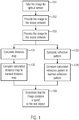
- Figure 1 shows a flow diagram of the processing of an obtained image including the taking of the image.
- an image is obtained by an optical sensor of a mobile device like a smart phone or tablet computer. While an image may be taken of an arbitrary situation, for the method according to the invention, it is intended that the image taken comprises an object wherein it is to be determined whether the object within the situation from which the image is taken is either the real object, which will mean that it is a three-dimensional object, or a spoof of the object, which will mean that it is a two-dimensional representation (like a photo) of the real object. In step 101, it is, however, not known to the mobile device nor any other entity whether the image taken shows the spoof or the real object.
- the image taken is then provided to a neutral network in step 102.
- a data structure corresponding to the image like a plurality of pixels having, for example, color values associated therewith, is provided to a neural network.
- the neural network can either reside on the mobile device by which the image was taken or it can reside on another computing entity to which the image is forwarded.
- a user can take the image using his or her smart phone and the information of the image (either completely or in a reduced or otherwise modified manner) is provided to the neural network that resides on a server of a company that provides a tool for, for example, identifying the user with the image of the real object.
- the further processing is thus either performed internally on the mobile device or is partially or completely performed outside of the mobile device on another computing entity.
- the invention is not limited in this regard although it is preferred that the whole method as described in figure 1 is performed on the mobile device in order to also allow its application in regions of the world where access to the mobile internet may be limited.
- the image is processed by the neural network.
- This can mean that either the complete image is processed or a reduced or otherwise manipulated or modified version of the image is processed.
- the image may first be reduced to a lesser number of pixels (for example 512 x 512 or 256 x 256 or 224 x 224 pixels) depending on how many pixels are necessary in order to determine an accurate identification of whether the image shows a spoof or the real three-dimensional object.
- step 103 can comprise the "preprocessing" of the image comprising for example the reduction of the number of pixels or any other preprocessing (for example changing the lighting conditions of the image or the like) that is deemed necessary.
- this step can also be performed between the step 101 of taking the image and step 103 of processing the image by the neural network at any suitable point.
- the manipulation of the image or the preprocessing of the image can be performed immediately after having taken the image before providing the image to the neural network in step 102 or it can be provided between providing the image to the neural network in step 102 and the actual beginning of the processing of the image by the neural network in step 103 comprising the steps 131 to 134 and the final step 104.
- a data structure corresponding to the original image is now processed in step 103 and the following step 131 to 134.
- the processing of the image by the neural network in step 103 can be split in two distinct processings of the image.
- the first refers to the calculation and processing of a distance map (steps 131 and 132) where the other refers to the calculation and further use of a reflection pattern.
- a distance map is calculated where the distance map associates each pixel with a calculated distance of the portions of the real world this pixel constitutes or represents within the image of the optical sensor of the mobile device.
- the distance map will comprise calculated distances for at least some pixels that correspond to the distance of the hand to the optical sensor and potentially other distances that are calculated but correspond to different objects within the image, for example a TV that is positioned within the background of the image taken or a house in the landscape constituting the background within the image taken. Therefore, there will be varying distances for pixels constituting or representing different objects within the real world from which the image was taken.
- the calculated distance map is, in a next step 132, then compared to a learned distance map of the neural network.
- the learned distance map can be split, in some embodiments, into at least two distance maps wherein a first learned distance map corresponds to a distance map that refers to images of real objects taken whereas a second learned distance map corresponds to a distance map for an image taken from a two-dimensional spoof of the object.
- the first will differ from the later in that the first shows varying distances over the whole range of the image whereas the second will have a smooth change of the distance associated with each pixel when moving from a first pixel to the second pixel. This is because in case a two-dimensional spoof (i.e.
- the distance of the pixels to the optical sensor can be calculated in accordance with the distance of a given point (the optical sensor) to a plane with arbitrary relative arrangement to the optical sensor (angulation), thus not showing any discontinuities.
- the comparison is preferably done completely within the neural network, e.g. as part of the processing of the image within the neural network, although it might also be possible to think of other realizations, where the comparison is done completely outside the neural network or by using additional software or hardware together with the neural network when comparing the obtained and calculated distance maps and reflection patterns, respectively.
- step 133 firstly comprises calculating a reflection pattern representative of light reflection associated with a plurality of pixels constituting at least a portion of the object within the image.
- the light reflection pattern may, for example, associate a value of brightness with each pixel within the image obtained. This value of brightness likewise corresponds (like for the distance map) to the actual brightness of the real situation from which the image was taken rather than to the brightness of the pixels, as the pixels are only data structures representing the real situation.
- portions of the real situation from which the image is taken that are near to the optical sensor will be comparably bright and reflect a significant amount of incident flash whereas more distant portions within the real situation or portions of objects that are tilted with respect to the optical sensor will reflect less of the flash and will, therefore, look comparably darker.
- the flash is a light source approximately in the form of a point
- the calculation of the reflection pattern when using the flash is much more accurate compared to the reflection pattern that can be obtained when only using the actual ambient light conditions because the ambient light is not a light source in the form of a point.
- the calculated reflection pattern is compared to a learned reflection pattern of the neural network.
- the neural network has preferably two learned reflection patterns where the first learnt reflection pattern corresponds to images of real objects taken whereas the second refers to a reflection pattern of a two-dimensional spoof. This comparison provides a result that is later used in step 104.
- step 104 it is finally determined in step 104 whether the image taken by the optical sensor contains or comprises a two-dimensional spoof of a real object or whether it comprises the real object.
- This determination is, according to the invention, done based on the outcome of the comparison in either step 132 and/or step 134. Accordingly, the result of those steps preferably is or comprises a number or any other information that can be used to later on determine whether there is shown a spoof or a real object within the image.
- the neural network will comprise a plurality of layers including one last layer.
- the last layer according to the invention can comprise a first and a second node where the first node provides an output that ranges from - ⁇ to + ⁇ regarding a real objection being determined during the comparison step in step 132 or 134 whereas the second node provides an output ranging from - ⁇ to + ⁇ for a spoof being identified during the steps 132 and/or 134.
- the output values may represent the sum of the differences constituting the obtained distance map and the learned distance matrix.
- the obtained distance map could be represented as a number of distances corresponding to specific pixels ij (i-th row, j-th column of the image) O and the learned distance map is L with each having entries O ij and L ij .
- an output can be provided as one example of the nodes in the last layer.
- a first output will correspond, e.g. to the structure L of a learned distance map for a real object and second output by the second node to the structure L of a learned distance map corresponding to a spoof. The same, of course, holds for the reflection pattern.
- the values ⁇ ( S ( x j )) will sum up to 1 in any case because the function above constitutes the calculation of a norm of a vector and is known as the soft max function.
- ⁇ 1 and ⁇ 2 can be used for the determining step 104 of figure 1 . If ⁇ 1 which constitutes the probability that the image shows a real object is greater than 0,5 (corresponding to ⁇ 2 ⁇ 0,5) the determination will result in the statements that the image shows a real object whereas, if ⁇ 2 > 0,5 (corresponding to corresponding to ⁇ 1 ⁇ 0,5) the determination will be that the image shows a spoof of the real object.
- the determination of whether a real object or a spoof of a real object is shown on the image can be used to, for example, trigger further steps like an indication to the user or another entity that the image taken shows a spoof of a real object and can, for example, thus not be used for identifiying the user in a log in procedure or other security relevant process like performing a bank transfer.
- the determination is in the affirmative, i.e. the image shows the real object
- a further process can be triggered that identifies the user based on user specific information that can be obtained from the real object. This can, for example, comprise processing the image of the real object further. If, for example, the real object is a hand or a finger tip, biometric characteristics like the finger print can be obtained from the image and can be used in identifying the user and, for example, performing a log in procedure or other process where this biometric characteristic is used.
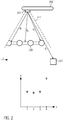
- Figures 2 and 3 show a schematic depiction of how the distance map will exemplarily look like for an image being taken from a real object and an image being taken from a spoof of the real object.
- the distance maps and the reflection patterns can usually not be represented in the form of a matrix.
- it will be assumed that it would be possible to have a 1 to 1 mapping between pixels and their associated distances/reflection properties. For explanatory purposes, this might be considered to, somehow, refer to a representation of the distance map and reflection patterns in the form of a matrix.
- figure 2 shows the situation where the image is taken from a real object using a mobile device 200 with an optical sensor 201 having a field of view 211 under which the image is taken.
- the depiction in figure 2 is a two-dimensional cross section of the real three-dimensional situation that would be viewed by the optical sensor in the real world.
- the real object from which the image is intended to be taken is the object 120 whereas, occasionally, additional objects may be present in the field of view 211 of the optical sensor, like the object 221.
- the image obtained from the shown two-dimensional arrangement will be a one-dimensional arrangement of pixels (corresponding to the image taken from the real three-dimensional situation being a two-dimensional image), where those pixels are arranged in the indicated direction x.
- the distance of real objects varies in an arbitrary manner and cannot be easily calculated using a function only depending on a limited amount of parameters because the arrangement of the real objects with respect to the optical sensor and the three-dimensional structure (in the depiction of figure 2a , the two-dimensional structure) of the object is usually unknown.
- figure 3 shows the case where an image of the real object (i.e. a two-dimensional spoof) is hold in front of the optical sensor.
- the situation obtained by the optical sensor is represented by a two-dimensional situation and the "image" obtained is, thus, one-dimensional as already explained with respect to the case in figure 2 .
- the image is hold with respect to the optical sensor 301 such that it is in parallel to the mobile device 300 to which the optical sensor is attached.
- the (two-dimensional) image of the spoof 330 is provided as perfect plane in front of the optical sensor.
- this distance map corresponding to pixels of the (one-dimensional) image obtained only depends on the distance of a given point in the image from the origin and the minimum distance d 0 and can thus be calculated using the above formula.
- a distance map of a real object or a real situation obtained by the optical sensor will significantly differ from a distance map of a two-dimensional spoof because the distance map of the two-dimensional spoof can be obtained by calculating the value of a function that has a limited number of parameters.
- the reflection pattern (more easily explained with respect to the light intensity) will also vary in line with the above formula or at least depending on the above formula because the intensity of light obtained from a given point in first order approximation is reciprocally dependent on the square of the distance.
- the reflection pattern will thus be a very complicated structure whereas, for the case that a two-dimensional spoof is shown to the optical sensor, the reflection pattern can be easily calculated using a function with a limited number of parameters.
- the neural network can make a reasoned determination on whether the image obtained shows a real object or a spoof of this object by comparing the learned distance maps (and, of course, reflection patterns) with the obtained distance maps and reflection patterns.
- the learned distance map and learned reflection pattern will usually be provided in the neural network in the form of a data structure where each entry constitutes the learned behavior of the distance or the corresponding reflection pattern.
- the obtained or calculated distance map and the obtained reflection pattern can be provided in the form of a data structure where each entry constitutes the distance (or the reflection pattern, respectively) in the obtained image.
- each entry in the respective data structures corresponds to a learned/calculated distance or reflection pattern of a specific pixel.
- the distance map (named for example L) and the reflection pattern (named for example Y), respectively, is built up in line with the obtained image.
- the image comprises 512x512 pixels per color value (i.e. 512x512x3)
- the distance map and the reflection pattern will be data structure of size 512x512 entries (not necessarily representable as a matrix with 512x512 entries) where each entry corresponds to one pixel in the obtained image (for one color value). The same holds for any other resolution of images.
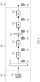
- Figure 4 shows the internal processing of a received input image in one layer 200 of the neural network according to one embodiment of the invention.
- the input image may either be the original image or an HSV converted data structure obtained from the original image.
- the data structure provided to the neural network more likely is a matrix corresponding to the input image after conversion into the HSV color space, as this more appropriately shows the luma values of the pixels, rather than the color values. This can result in more efficient calculation of the distance map and reflection pattern.
- This layer 200 may be a layer that is, in processing order of the original input image through the neural network, the first layer that receives the original input image after step 102 explained above or any intermediate layer that is arranged between two further layers 240 and 250 of the neural network or the layer 200 may even be the last layer of the neural network that will, in the end, provide an output according to step 104 as explained with reference to figure 1 . In the last case, the layer will have two output nodes as explained above to provide a corresponding output for spoof identification and identification of a real object within the image.
- the layer 200 will receive an input 230 that at least somehow corresponds to the originally obtained image.
- This input is preferably provided in the form of at least one matrix that has the dimension N ⁇ M where N and M are integers greater than 0.
- the matrix may, for example, represent the pixels in the image for at least one color value (for example red) or the HSV converted image.
- the entries in this matrix thus may have values that correspond to the value of the respective color (in the example case red) of this specific pixel or its luma value.
- the input may not be identical to the obtained image but can be a matrix P that was obtained from the matrix representing the original image by some processing through layers in the neural network or even by some pre-processing (for example reduction in resolution as explained above).
- the input 230 will be assumed to correspond to the N ⁇ M matrix that represents the originally obtained image and each entry in this N ⁇ M matrix corresponds to a value of a color (for example red) of a pixel in the respective image.
- a color for example red
- the input 230 is received by the depthwise convolutional layer 211 for processing.
- a kernel K is used to calculate inner products with the matrix.
- the kernel is run over the matrix in so called “strides”. While the following example will use values for horizontal and vertical stride widths of 1, any other value greater than 1 can be used as long as the stride widths are integers greater than 0.
- the kernel K is of size S ⁇ T , where S and T are integers and smaller than N and M.
- an extended matrix Z can be used for calculating the inner products with the kernel. This extended matrix Z is obtained by "attaching", to the original matrix I, lines and rows above the first line and below the last line as well as left to the first row and right to the last row.
- the padding will usually comprise that a number P w of lines is added in the line direction and a number P h of rows is added to the row direction.
- the number P w can equal S-1 and the number P h can equal T-1, such that any inner product calculated between Z and the kernel contains at least one entry of the original matrix I.
- the resulting matrix Z will thus be of size ( N + 2 P w ) ⁇ ( M + 2 P h ).
- the new matrix obtained by calculating all inner products and arranging them properly according to lines and rows will generally be of size N ⁇ S + 2 P w W w + 1 ⁇ M ⁇ T + 2 P h W h + 1 , where W w and W h define the stride width in the direction of lines and the direction of the rows, respectively. It is clear that only those paddings and those stride widths are allowed for a given kernel K with size S ⁇ T that result in integers for the size of the new matrix. Furthermore, the stride widths W w and W h are preferably smaller than S and T, respectively, as otherwise the kernel would be moved over the matrix I in a manner that some lines or rows of the original matrix are left out in calculating the new matrix.
- the received input matrix 230 is used to form an inner product with the kernel K that has the size S x S where S ⁇ N, M.
- the inner product is calculated for each reduced matrix of the original N ⁇ M matrix where the reduced matrix is of size S x S and contains coherent entries in the original N ⁇ M matrix.
- the matrix P is calculated that has the size ( N - S + 1) ⁇ ( M - S + 1).
- the kernel K constitutes entries that are obtained through a learning process where the neural network is trained in order to properly identify the intended objects, i.e. distinguish between spoofs of objects and the real objects.
- the kernel K used in the layer 200 of the neural network is not necessarily identical in size and entries to the kernels used in other layers of the respective neural network. Additionally, the entries in the kernel do not need to be identical to each other but at least constitute numbers being larger or equal to 0. The entries may be considered to represent "weights" that are obtained through learning of the neural network.
- this result 231 is forwarded to the first batch normalize 212 that follows in the processing order depicted with the arrows in figure 4 after the depthwise convolutional layer 211.
- the batch normalizer attempts to normalize the received result matrix 231. This is achieved by calculating the sum over each of the entries in the ( N - S + 1) ⁇ ( M - S + 1) matrix and dividing it by the number of entries in the ( N - S + 1) ⁇ ( M - S + 1) matrix.
- V ⁇ ij P ij n ⁇ m
- n and m represent the number of lines and columns/rows in the N ⁇ M matrix or the number of lines and columns in the matrix P.
- the items P ij are the entries of the matrix P where a given item P ij is the element in the matrix in line i and column j.
- the values in the reduced matrix P' are normalized such that anomalies in the one or the other direction (extremely large values or extremely low values) are filtered out.
- the item P' ij is calculated by dividing the term P ij - V by the standard deviation corresponding to the mean value V.
- the result 232 created by the first batch normalizer 212 is a matrix still having (in the example given in figure 4 ) the size ( N - S + 1) ⁇ ( M - S + 1) since, until now, no further dimensional reduction of the matrix was performed.
- the result 232 is then provided to the first rectified linear unit 213 that follows the first batch normalizer 212.
- the result 233 thus output by the first rectified linear unit 213 still is a matrix of shape/size ( N - S + 1) ⁇ ( M - S + 1)and this matrix is forwarded to the pointwise convolutional layer 221.
- This pointwise convolutional layer 221 creates a result 234.
- This result 234 is created by the pointwise convolutional layer 221 by taking each entry in the ( N - S + 1) ⁇ ( M - S + 1) matrix 233 and multiplying this entry with a weight ⁇ .
- ⁇ preferably is a number that is greater than 0 in any case and this number is identical for each entry in the ( N - S + 1) ⁇ ( M - S + 1)matrix.
- the result 234 that is obtained from the pointwise convolutional layer 221 thus is a matrix having the same size ( N - S + 1) ⁇ ( M - S + 1)but where each entry is multiplied with the weight ⁇ .
- the result 234 is then provided to the second batch normalizer 222 where it is normalized in the manner as explained for the first batch normalizer 212 and a normalized matrix P' of the same dimension as the result 235 is calculated and this matrix/result 235 is forwarded to the second rectified linear unit 223 where a rectification function is applied to obtain a result/matrix P 236 that is then forwarded to the next layer in the neural network or, if no other layer follows in the neural network, the result 236 is provided as an output.
- the method of figure 5 begins with the provision of training data 401.
- the training data may be constituted by a plurality of images of real objects as well as images of spoofs of real objects.
- the images may comprise a number of images of real hands or fingers or the like and images of images (i.e. spoofs) of those objects.
- the images may be multiplied by using, from the same image, rotated, highlighted, darkened, enlarged or otherwise modified copies that are introduced as training data.
- modifications involving image flips, image rotation and translation, shears, crops, multiplication to increase brightness and Gaussian blurs may be used to obtain a larger number of training images.
- Arbitrary combinations of the mentioned techniques may also be used.
- the values ⁇ 1 and ⁇ 2 provided according to item 408 are the values indicating the "correct" output of the first node and second node of the last layer in the neural network that provide the probability of the image showing a spoof of an object or a real object. These values are provided for each image in the training data.
- one specific input image 402 is provided to the neural network in a training environment where, in addition to the neural network, an optimizer 407 and a loss function calculator 406 are provided.
- the input image is, in a first round, processed using the depthwise convolutional layer and the first batch normalizer as well as the first rectified linear unit 403, summarized as DCBR, and is then transferred to the pointwise convolutional layer, the second batch normalizer and the second rectified linear unit, summarized as PCBR, where they are processed in line with the description given in figure 4 .
- This means the steps or the sections 403 and 404 depicted in figure 5 are run through preferably a number of times, like thirteen times, as described with reference to figure 4 using, in each section 403 and 404 the corresponding weights for the pointwise convolutional layer (PC) and the kernel K of the depthwise convolutional layer (DC).
- the first and second batch normalizers as well as the rectified linear units of items 403 and 404 work in the manner as explained above with respect to fig. 4 .
- the cycle is repeated for the very same image and the resulting values ⁇ 1 and ⁇ 2 are provided to the loss function and compared to the correct values ⁇ 1 and ⁇ 2 , the result of which being then provided to the optimizer 407 which, once again, modifies the weights.
- This procedure is performed as long as the difference between the resulting values ⁇ 1 ( n ) and ⁇ 2 ( n ) (where n constitutes the n-th iteration of these values) to the values ⁇ 1 and ⁇ 2 of item 408 exceed a given threshold which, in essence, corresponds to the determination accuracy of spoofs and real objects that is intended.
- the next input image 402 is taken from the training data 401 and the corresponding values ⁇ 1 and ⁇ 2 are provided to the loss function. Then, the process explained is repeated again for the new image and the optimal weights for the pointwise convolutional layer and the depthwise convolutional layer are obtained. This is repeated until a specific combination of weights results in appropriate identification accuracy for all input images. The combination of weights that is then obtained is output as final weights 410.
- the output of the neural network in step 405 will not only be the respective values ⁇ 1 ( n ) and ⁇ 2 ( n ) but also a distance map and/or a reflection pattern to compare with the preset distance map and/or reflection pattern obtained via the input 408.
- the neural network that is provided to the mobile device is already fully adapted to the determination whether an image shows a real object or only a two-dimensional spoof of the real object.
- an application can be provided that is smaller than one megabyte, thus allowing for utilization on a mobile device in isolation even without any access to additional data sources via the internet or the like. This makes it suitable for application in environments where no access to wireless networks or the like is possible. Additionally, the processor power required for running this application is reduced to a minimum while still yielding appropriate determinations of real objects that can be used for later on performed identification of the user by, for example, extracting biometric characteristics from an identified real object in order to use this biometric characteristics for further security-related processes.
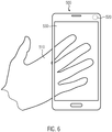
- figure 6 depicts a mobile device in the form of a smartphone according to one embodiment of the invention.
- the mobile device 500 is embodied as a smartphone as is presently known. It comprises an optical sensor 520 preferably on the backside of the camera which is opposite to the side of the mobile device 500 on which the display 530 is provided.
- the camera can be a camera having a resolution of 1 MP, 2MP or even more, thus, for example an HD camera. It can be provided with a flashlight but does not need to. It can also be adapted to take real-time images with a reduced resolution and once the camera is activated, the display 530 may show a representation of what the camera actually "sees". This can be, for example, a hand 510.
Landscapes
- Engineering & Computer Science (AREA)
- Theoretical Computer Science (AREA)
- Physics & Mathematics (AREA)
- General Physics & Mathematics (AREA)
- Multimedia (AREA)
- Computer Vision & Pattern Recognition (AREA)
- Human Computer Interaction (AREA)
- Evolutionary Computation (AREA)
- Artificial Intelligence (AREA)
- Health & Medical Sciences (AREA)
- General Health & Medical Sciences (AREA)
- Software Systems (AREA)
- Computing Systems (AREA)
- Life Sciences & Earth Sciences (AREA)
- Data Mining & Analysis (AREA)
- Molecular Biology (AREA)
- Biomedical Technology (AREA)
- General Engineering & Computer Science (AREA)
- Medical Informatics (AREA)
- Databases & Information Systems (AREA)
- Biophysics (AREA)
- Mathematical Physics (AREA)
- Computational Linguistics (AREA)
- Biodiversity & Conservation Biology (AREA)
- Signal Processing (AREA)
- Bioinformatics & Computational Biology (AREA)
- Evolutionary Biology (AREA)
- Bioinformatics & Cheminformatics (AREA)
- Image Analysis (AREA)
- Collating Specific Patterns (AREA)
- Image Processing (AREA)
- Computer Security & Cryptography (AREA)
- Debugging And Monitoring (AREA)
- Length Measuring Devices By Optical Means (AREA)
- Computer Hardware Design (AREA)
- Measurement Of The Respiration, Hearing Ability, Form, And Blood Characteristics Of Living Organisms (AREA)
- Mobile Radio Communication Systems (AREA)
Priority Applications (6)
| Application Number | Priority Date | Filing Date | Title |
|---|---|---|---|
| US17/050,184 US11495050B2 (en) | 2018-03-16 | 2019-05-09 | Method for distinguishing a real three-dimensional object from a two-dimensional spoof of the real object |
| BR112020021946-0A BR112020021946A2 (pt) | 2018-03-16 | 2019-05-09 | método para a distinção de um objeto tridimensional real de uma mistificação bidimensional do objeto real e dispositivo móvel |
| JP2020560255A JP7304082B2 (ja) | 2018-03-16 | 2019-05-09 | 三次元実物体を実物体の二次元のスプーフと区別するための方法 |
| PCT/IB2019/053824 WO2019207557A1 (en) | 2018-03-16 | 2019-05-09 | Method for distinguishing a real three-dimensional object from a two-dimensional spoof of the real object |
| ZA2020/07383A ZA202007383B (en) | 2018-03-16 | 2020-11-26 | Method for distinguishing a real three-dimensional object from a two-dimensional spoof of the real object |
| US17/948,029 US12106597B2 (en) | 2018-03-16 | 2022-09-19 | Method for distinguishing a real three-dimensional object from a two-dimensional spoof of the real object |
Applications Claiming Priority (1)
| Application Number | Priority Date | Filing Date | Title |
|---|---|---|---|
| EP18382174.3A EP3540635B1 (de) | 2018-03-16 | 2018-03-16 | Verfahren zur identifizierung eines objekts innerhalb eines bildes und mobile vorrichtung zur durchführung des verfahrens |
Publications (1)
| Publication Number | Publication Date |
|---|---|
| EP3540636A1 true EP3540636A1 (de) | 2019-09-18 |
Family
ID=61768233
Family Applications (3)
| Application Number | Title | Priority Date | Filing Date |
|---|---|---|---|
| EP18382174.3A Active EP3540635B1 (de) | 2018-03-16 | 2018-03-16 | Verfahren zur identifizierung eines objekts innerhalb eines bildes und mobile vorrichtung zur durchführung des verfahrens |
| EP18206807.2A Active EP3540633B1 (de) | 2018-03-16 | 2018-03-16 | Verfahren zur identifizierung eines objekts innerhalb eines bildes und mobile vorrichtung zur durchführung des verfahrens |
| EP18382295.6A Ceased EP3540636A1 (de) | 2018-03-16 | 2018-04-27 | Verfahren zur unterscheidung eines realen dreidimensionalen objektes von einer zweidimensionalen simulation des realen objektes |
Family Applications Before (2)
| Application Number | Title | Priority Date | Filing Date |
|---|---|---|---|
| EP18382174.3A Active EP3540635B1 (de) | 2018-03-16 | 2018-03-16 | Verfahren zur identifizierung eines objekts innerhalb eines bildes und mobile vorrichtung zur durchführung des verfahrens |
| EP18206807.2A Active EP3540633B1 (de) | 2018-03-16 | 2018-03-16 | Verfahren zur identifizierung eines objekts innerhalb eines bildes und mobile vorrichtung zur durchführung des verfahrens |
Country Status (13)
| Country | Link |
|---|---|
| US (4) | US11508184B2 (de) |
| EP (3) | EP3540635B1 (de) |
| JP (2) | JP7386545B2 (de) |
| KR (4) | KR102554724B1 (de) |
| CN (1) | CN111989689B (de) |
| AU (2) | AU2019234110B2 (de) |
| BR (1) | BR112020021946A2 (de) |
| CA (3) | CA3093966C (de) |
| ES (2) | ES2837382T3 (de) |
| MX (3) | MX2020009382A (de) |
| PE (3) | PE20240541A1 (de) |
| WO (2) | WO2019175846A1 (de) |
| ZA (2) | ZA202006256B (de) |
Cited By (2)
| Publication number | Priority date | Publication date | Assignee | Title |
|---|---|---|---|---|
| US11526974B2 (en) | 2020-06-02 | 2022-12-13 | Samsung Sds Co., Ltd. | Method for photographing and reading an image, and apparatus therefor |
| EP4657388A1 (de) | 2024-05-28 | 2025-12-03 | Identy Inc. | Computerimplementiertes verfahren zum gemeinsamen trainieren von mindestens zwei verschiedenen spoof-detektionssystemen |
Families Citing this family (21)
| Publication number | Priority date | Publication date | Assignee | Title |
|---|---|---|---|---|
| EP3540635B1 (de) * | 2018-03-16 | 2020-08-26 | Identy Inc. | Verfahren zur identifizierung eines objekts innerhalb eines bildes und mobile vorrichtung zur durchführung des verfahrens |
| WO2020051776A1 (en) * | 2018-09-11 | 2020-03-19 | Intel Corporation | Method and system of deep supervision object detection for reducing resource usage |
| ES2943287T3 (es) * | 2019-02-26 | 2023-06-12 | Identy Inc | Método para verificar la identidad de un usuario identificando un objeto dentro de una imagen que tiene una característica biométrica del usuario y separando una porción de la imagen que comprende la característica biométrica de otras porciones de la imagen |
| US11189028B1 (en) * | 2020-05-15 | 2021-11-30 | Retrace Labs | AI platform for pixel spacing, distance, and volumetric predictions from dental images |
| WO2021151947A1 (en) * | 2020-01-28 | 2021-08-05 | Universidad Autonoma De Madrid | Method to generate training data for a bot detector module, bot detector module trained from training data generated by the method and bot detection system |
| ES2971682T3 (es) | 2020-04-09 | 2024-06-06 | Identy Inc | Detección de vivacidad usando un dispositivo que comprende una fuente de iluminación |
| CN111598110B (zh) * | 2020-05-11 | 2023-04-28 | 重庆大学 | 基于网格细胞记忆的hog算法图像识别方法 |
| US11741747B2 (en) | 2021-01-13 | 2023-08-29 | Ford Global Technologies, Llc | Material spectroscopy |
| US11657589B2 (en) | 2021-01-13 | 2023-05-23 | Ford Global Technologies, Llc | Material spectroscopy |
| US20220222466A1 (en) | 2021-01-13 | 2022-07-14 | Ford Global Technologies, Llc | Material spectroscopy |
| US11443527B2 (en) | 2021-01-13 | 2022-09-13 | Ford Global Technologies, Llc | Material spectroscopy |
| KR102672353B1 (ko) * | 2021-01-25 | 2024-06-05 | 숭실대학교산학협력단 | 사진 촬영 기반 낙서 드로잉 장치 및 방법 |
| WO2023272604A1 (zh) * | 2021-06-30 | 2023-01-05 | 东莞市小精灵教育软件有限公司 | 基于生物特征识别的定位方法及装置 |
| CN113449652A (zh) * | 2021-06-30 | 2021-09-28 | 东莞市小精灵教育软件有限公司 | 基于生物特征识别的定位方法及装置 |
| CN113706647B (zh) * | 2021-07-30 | 2024-02-13 | 浪潮电子信息产业股份有限公司 | 一种图像上色方法及相关装置 |
| CN117751380A (zh) * | 2021-08-05 | 2024-03-22 | 富士通株式会社 | 生成方法、信息处理装置以及生成程序 |
| US12223764B2 (en) * | 2022-02-28 | 2025-02-11 | Armatura Llc | System and method for rotation invariant fingerprint recognition |
| CN117437430A (zh) * | 2022-07-12 | 2024-01-23 | 北京字跳网络技术有限公司 | 图像处理方法、装置、设备、介质及产品 |
| CN117037221B (zh) * | 2023-10-08 | 2023-12-29 | 腾讯科技(深圳)有限公司 | 活体检测方法、装置、计算机设备及存储介质 |
| WO2025141668A1 (ja) * | 2023-12-25 | 2025-07-03 | 楽天グループ株式会社 | 動画処理システム、動画処理方法、及びプログラム |
| EP4583067A1 (de) * | 2024-01-08 | 2025-07-09 | Identy Inc. | Verfahren zur unterscheidung eines realen objekts in einem bild von einer täuschung des realen objekts |
Citations (1)
| Publication number | Priority date | Publication date | Assignee | Title |
|---|---|---|---|---|
| WO2018106987A1 (en) * | 2016-12-08 | 2018-06-14 | Veridium Ip Limited | Systems and methods for performing fingerprint based user authentication using imagery captured using mobile devices |
Family Cites Families (31)
| Publication number | Priority date | Publication date | Assignee | Title |
|---|---|---|---|---|
| US5978495A (en) * | 1996-07-17 | 1999-11-02 | Intelnet Inc. | Method and apparatus for accurate determination of the identity of human beings |
| US6072891A (en) * | 1997-02-21 | 2000-06-06 | Dew Engineering And Development Limited | Method of gathering biometric information |
| JP4085470B2 (ja) * | 1998-05-29 | 2008-05-14 | オムロン株式会社 | 個人識別装置、個人識別方法および個人識別プログラムを記録した記録媒体 |
| FR2826443B1 (fr) * | 2001-06-21 | 2003-10-10 | Gilles Cavallucci | Procede et dispositif de detection optique de la position d'un objet |
| JP4734980B2 (ja) | 2005-03-15 | 2011-07-27 | オムロン株式会社 | 顔認証装置およびその制御方法、顔認証装置を備えた電子機器、顔認証装置制御プログラム、ならびに該プログラムを記録した記録媒体 |
| US8542928B2 (en) * | 2005-09-26 | 2013-09-24 | Canon Kabushiki Kaisha | Information processing apparatus and control method therefor |
| CN103336941A (zh) * | 2006-07-19 | 2013-10-02 | 光谱辨识公司 | 多重生物测定多谱成像器 |
| JP2008257327A (ja) * | 2007-04-02 | 2008-10-23 | Omron Corp | 照合装置 |
| JP2015529365A (ja) | 2012-09-05 | 2015-10-05 | エレメント,インク. | カメラ付きデバイスに関連する生体認証のためのシステム及び方法 |
| JP6304999B2 (ja) * | 2013-10-09 | 2018-04-04 | アイシン精機株式会社 | 顔検出装置、方法およびプログラム |
| JP6187817B2 (ja) * | 2013-10-09 | 2017-08-30 | アイシン精機株式会社 | 顔検出装置、方法およびプログラム |
| US10025915B2 (en) * | 2013-12-05 | 2018-07-17 | Lenovo (Singapore) Pte. Ltd. | Contact signature authentication of user of device |
| CA2939637A1 (en) * | 2014-02-12 | 2015-08-20 | Advanced Optical Systems, Inc. | On-the-go touchless fingerprint scanner |
| US9195879B1 (en) * | 2014-08-31 | 2015-11-24 | Qualcomm Incorporated | Air/object determination for biometric sensors |
| KR102290892B1 (ko) * | 2014-12-12 | 2021-08-19 | 엘지전자 주식회사 | 이동단말기 및 그것의 제어방법 |
| US11120478B2 (en) | 2015-01-12 | 2021-09-14 | Ebay Inc. | Joint-based item recognition |
| US9424458B1 (en) * | 2015-02-06 | 2016-08-23 | Hoyos Labs Ip Ltd. | Systems and methods for performing fingerprint based user authentication using imagery captured using mobile devices |
| US10339362B2 (en) * | 2016-12-08 | 2019-07-02 | Veridium Ip Limited | Systems and methods for performing fingerprint based user authentication using imagery captured using mobile devices |
| BR112017027057B1 (pt) | 2015-06-16 | 2020-05-12 | EyeVerify Inc. | Sistemas e métodos para detecção de falsificação e análise de presença viva e meio legível por computador |
| KR102439938B1 (ko) * | 2015-08-03 | 2022-09-05 | 삼성전자주식회사 | 사용자 인증을 위한 멀티-모달 퓨전 방법 및 사용자 인증 방법 |
| WO2017127571A1 (en) | 2016-01-19 | 2017-07-27 | Magic Leap, Inc. | Augmented reality systems and methods utilizing reflections |
| CN106056095A (zh) * | 2016-06-13 | 2016-10-26 | 北京小米移动软件有限公司 | 指纹处理的方法和装置 |
| KR102483642B1 (ko) * | 2016-08-23 | 2023-01-02 | 삼성전자주식회사 | 라이브니스 검사 방법 및 장치 |
| US11157814B2 (en) * | 2016-11-15 | 2021-10-26 | Google Llc | Efficient convolutional neural networks and techniques to reduce associated computational costs |
| US10216977B2 (en) * | 2017-01-06 | 2019-02-26 | Qualcomm Incorporated | Progressive multiple fingerprint enrollment and matching, and dynamic user account transitions |
| EP3540635B1 (de) | 2018-03-16 | 2020-08-26 | Identy Inc. | Verfahren zur identifizierung eines objekts innerhalb eines bildes und mobile vorrichtung zur durchführung des verfahrens |
| CN108810616B (zh) * | 2018-05-31 | 2019-06-14 | 广州虎牙信息科技有限公司 | 目标定位方法、视频显示方法、装置、设备和存储介质 |
| CN109145743A (zh) * | 2018-07-19 | 2019-01-04 | 叶涵 | 一种基于深度学习的图像识别方法及装置 |
| JP7130905B2 (ja) * | 2019-06-18 | 2022-09-06 | ユーエービー “ニューロテクノロジー” | フィードフォワード畳み込みニューラルネットワークを使用した高速且つ堅牢な皮膚紋理の印のマニューシャの抽出 |
| EP4361941A1 (de) * | 2022-10-27 | 2024-05-01 | Carl Zeiss Meditec AG | Verfahren, prozessoreinheit und system zur verarbeitung von bildern |
| CN116486074B (zh) * | 2023-03-30 | 2025-08-22 | 浙江工业大学 | 一种基于局部和全局上下文信息编码的医学图像分割方法 |
-
2018
- 2018-03-16 EP EP18382174.3A patent/EP3540635B1/de active Active
- 2018-03-16 ES ES18206807T patent/ES2837382T3/es active Active
- 2018-03-16 EP EP18206807.2A patent/EP3540633B1/de active Active
- 2018-03-16 ES ES18382174T patent/ES2828358T3/es active Active
- 2018-04-27 EP EP18382295.6A patent/EP3540636A1/de not_active Ceased
-
2019
- 2019-03-15 WO PCT/IB2019/052126 patent/WO2019175846A1/en not_active Ceased
- 2019-03-15 MX MX2020009382A patent/MX2020009382A/es unknown
- 2019-03-15 CN CN201980019837.1A patent/CN111989689B/zh active Active
- 2019-03-15 CA CA3093966A patent/CA3093966C/en active Active
- 2019-03-15 AU AU2019234110A patent/AU2019234110B2/en active Active
- 2019-03-15 US US16/981,262 patent/US11508184B2/en active Active
- 2019-03-15 KR KR1020207029856A patent/KR102554724B1/ko active Active
- 2019-03-15 CA CA3215158A patent/CA3215158C/en active Active
- 2019-03-15 KR KR1020237022979A patent/KR20230107415A/ko not_active Ceased
- 2019-03-15 PE PE2023002278A patent/PE20240541A1/es unknown
- 2019-03-15 PE PE2020001377A patent/PE20201181A1/es unknown
- 2019-03-15 PE PE2023003138A patent/PE20250719A1/es unknown
- 2019-03-15 JP JP2020571920A patent/JP7386545B2/ja active Active
- 2019-05-09 JP JP2020560255A patent/JP7304082B2/ja active Active
- 2019-05-09 KR KR1020207034340A patent/KR102442844B1/ko active Active
- 2019-05-09 US US17/050,184 patent/US11495050B2/en active Active
- 2019-05-09 CA CA3098286A patent/CA3098286C/en active Active
- 2019-05-09 WO PCT/IB2019/053824 patent/WO2019207557A1/en not_active Ceased
- 2019-05-09 MX MX2020011313A patent/MX2020011313A/es unknown
- 2019-05-09 BR BR112020021946-0A patent/BR112020021946A2/pt active Search and Examination
- 2019-05-09 KR KR1020227030334A patent/KR102629380B1/ko active Active
-
2020
- 2020-09-09 MX MX2024003152A patent/MX2024003152A/es unknown
- 2020-10-08 ZA ZA2020/06256A patent/ZA202006256B/en unknown
- 2020-11-26 ZA ZA2020/07383A patent/ZA202007383B/en unknown
-
2022
- 2022-04-28 AU AU2022202817A patent/AU2022202817B2/en active Active
- 2022-06-28 US US17/851,381 patent/US12087078B2/en active Active
- 2022-09-19 US US17/948,029 patent/US12106597B2/en active Active
Patent Citations (1)
| Publication number | Priority date | Publication date | Assignee | Title |
|---|---|---|---|---|
| WO2018106987A1 (en) * | 2016-12-08 | 2018-06-14 | Veridium Ip Limited | Systems and methods for performing fingerprint based user authentication using imagery captured using mobile devices |
Non-Patent Citations (4)
| Title |
|---|
| ATOUM YOUSEF ET AL: "Face anti-spoofing using patch and depth-based CNNs", 2017 IEEE INTERNATIONAL JOINT CONFERENCE ON BIOMETRICS (IJCB), IEEE, 1 October 2017 (2017-10-01), pages 319 - 328, XP033308629, DOI: 10.1109/BTAS.2017.8272713 * |
| DI TANG: "Face Flashing: a Secure Liveness Detection Protocol based on Light Reflections", ARXIV.ORG, 6 January 2018 (2018-01-06), XP080850899 * |
| Google's TensorFlow (open-source software) * |
| MAYANK VATSA: "Deep Learning in Biometrics", 1 January 2018, CRC - TAYLOR & FRANCIS, pages: 246 - 297, XP055523424 * |
Cited By (3)
| Publication number | Priority date | Publication date | Assignee | Title |
|---|---|---|---|---|
| US11526974B2 (en) | 2020-06-02 | 2022-12-13 | Samsung Sds Co., Ltd. | Method for photographing and reading an image, and apparatus therefor |
| EP4657388A1 (de) | 2024-05-28 | 2025-12-03 | Identy Inc. | Computerimplementiertes verfahren zum gemeinsamen trainieren von mindestens zwei verschiedenen spoof-detektionssystemen |
| WO2025248456A1 (en) | 2024-05-28 | 2025-12-04 | Identy Inc. | Computer-implemented method for jointly training at least two different spoof-detection systems |
Also Published As
Similar Documents
| Publication | Publication Date | Title |
|---|---|---|
| US12106597B2 (en) | Method for distinguishing a real three-dimensional object from a two-dimensional spoof of the real object | |
| CN113743426B (zh) | 一种训练方法、装置、设备以及计算机可读存储介质 | |
| CN113449548B (zh) | 更新物体识别模型的方法和装置 | |
| US20220237943A1 (en) | Method and apparatus for adjusting cabin environment | |
| US10445602B2 (en) | Apparatus and method for recognizing traffic signs | |
| CN112016546A (zh) | 一种文本区域的定位方法及装置 | |
| CN120047678B (zh) | 一种用于异常大米检测的轻量级目标检测方法及系统 | |
| US12340619B2 (en) | Liveliness detection using a device comprising an illumination source | |
| CN111951283A (zh) | 一种基于深度学习的医学图像识别方法及系统 | |
| CN110427912A (zh) | 一种基于深度学习的人脸检测方法及其相关装置 | |
| WO2024078112A1 (zh) | 一种舾装件智能识别方法、计算机设备 | |
| CN108960005B (zh) | 一种智能视觉物联网中对象视觉标签的建立及显示方法、系统 | |
| CN116543433A (zh) | 一种基于改进YOLOv7模型的口罩佩戴检测方法和装置 | |
| JP7239002B2 (ja) | 物体数推定装置、制御方法、及びプログラム | |
| Shinde et al. | Feedforward back propagation neural network (FFBPNN) based approach for the identification of handwritten math equations | |
| CN119380267A (zh) | 绿色注意力和联合特征融合的田间杂草检测方法及系统 | |
| Pal et al. | Exploration of a shape-focused autoencoder for improved ear biometrics | |
| Hiremath et al. | Age detection based on facial features using support vector machine | |
| US20240037910A1 (en) | Quantum Method and System for Classifying Images | |
| JP2018005505A (ja) | 画像認識パラメータ設定装置、画像認識パラメータ設定方法、および画像認識パラメータ設定プログラム | |
| CN118230354A (zh) | 一种基于改进YOLOv5的复杂场景下手语识别方法 | |
| JP2023076881A (ja) | 機械学習モデルの学習に使用される複数の学習データの中から不適切な不備データを抽出する方法、情報処理装置、及び、コンピュータープログラム | |
| Chen et al. | Learn to focus on objects for visual detection | |
| CN114565940B (zh) | 一种目标检测方法和装置 | |
| EP4310793A1 (de) | Quantenverfahren und -system zur klassifizierung von bildern |
Legal Events
| Date | Code | Title | Description |
|---|---|---|---|
| PUAI | Public reference made under article 153(3) epc to a published international application that has entered the european phase |
Free format text: ORIGINAL CODE: 0009012 |
|
| STAA | Information on the status of an ep patent application or granted ep patent |
Free format text: STATUS: REQUEST FOR EXAMINATION WAS MADE |
|
| 17P | Request for examination filed |
Effective date: 20190123 |
|
| AK | Designated contracting states |
Kind code of ref document: A1 Designated state(s): AL AT BE BG CH CY CZ DE DK EE ES FI FR GB GR HR HU IE IS IT LI LT LU LV MC MK MT NL NO PL PT RO RS SE SI SK SM TR |
|
| AX | Request for extension of the european patent |
Extension state: BA ME |
|
| STAA | Information on the status of an ep patent application or granted ep patent |
Free format text: STATUS: EXAMINATION IS IN PROGRESS |
|
| 17Q | First examination report despatched |
Effective date: 20201126 |
|
| STAA | Information on the status of an ep patent application or granted ep patent |
Free format text: STATUS: THE APPLICATION HAS BEEN REFUSED |
|
| 18R | Application refused |
Effective date: 20211009 |