EP3540814B1 - Plaque d'extrémité, boîtier et module de batterie - Google Patents
Plaque d'extrémité, boîtier et module de batterie Download PDFInfo
- Publication number
- EP3540814B1 EP3540814B1 EP18187077.5A EP18187077A EP3540814B1 EP 3540814 B1 EP3540814 B1 EP 3540814B1 EP 18187077 A EP18187077 A EP 18187077A EP 3540814 B1 EP3540814 B1 EP 3540814B1
- Authority
- EP
- European Patent Office
- Prior art keywords
- disposed
- end plate
- battery module
- output electrode
- output
- Prior art date
- Legal status (The legal status is an assumption and is not a legal conclusion. Google has not performed a legal analysis and makes no representation as to the accuracy of the status listed.)
- Active
Links
Images



Classifications
-
- H—ELECTRICITY
- H01—ELECTRIC ELEMENTS
- H01M—PROCESSES OR MEANS, e.g. BATTERIES, FOR THE DIRECT CONVERSION OF CHEMICAL ENERGY INTO ELECTRICAL ENERGY
- H01M50/00—Constructional details or processes of manufacture of the non-active parts of electrochemical cells other than fuel cells, e.g. hybrid cells
- H01M50/50—Current conducting connections for cells or batteries
- H01M50/502—Interconnectors for connecting terminals of adjacent batteries; Interconnectors for connecting cells outside a battery casing
-
- H—ELECTRICITY
- H01—ELECTRIC ELEMENTS
- H01M—PROCESSES OR MEANS, e.g. BATTERIES, FOR THE DIRECT CONVERSION OF CHEMICAL ENERGY INTO ELECTRICAL ENERGY
- H01M10/00—Secondary cells; Manufacture thereof
- H01M10/04—Construction or manufacture in general
- H01M10/0468—Compression means for stacks of electrodes and separators
-
- H—ELECTRICITY
- H01—ELECTRIC ELEMENTS
- H01M—PROCESSES OR MEANS, e.g. BATTERIES, FOR THE DIRECT CONVERSION OF CHEMICAL ENERGY INTO ELECTRICAL ENERGY
- H01M10/00—Secondary cells; Manufacture thereof
- H01M10/05—Accumulators with non-aqueous electrolyte
- H01M10/052—Li-accumulators
- H01M10/0525—Rocking-chair batteries, i.e. batteries with lithium insertion or intercalation in both electrodes; Lithium-ion batteries
-
- H—ELECTRICITY
- H01—ELECTRIC ELEMENTS
- H01M—PROCESSES OR MEANS, e.g. BATTERIES, FOR THE DIRECT CONVERSION OF CHEMICAL ENERGY INTO ELECTRICAL ENERGY
- H01M10/00—Secondary cells; Manufacture thereof
- H01M10/42—Methods or arrangements for servicing or maintenance of secondary cells or secondary half-cells
- H01M10/425—Structural combination with electronic components, e.g. electronic circuits integrated to the outside of the casing
-
- H—ELECTRICITY
- H01—ELECTRIC ELEMENTS
- H01M—PROCESSES OR MEANS, e.g. BATTERIES, FOR THE DIRECT CONVERSION OF CHEMICAL ENERGY INTO ELECTRICAL ENERGY
- H01M50/00—Constructional details or processes of manufacture of the non-active parts of electrochemical cells other than fuel cells, e.g. hybrid cells
- H01M50/20—Mountings; Secondary casings or frames; Racks, modules or packs; Suspension devices; Shock absorbers; Transport or carrying devices; Holders
- H01M50/204—Racks, modules or packs for multiple batteries or multiple cells
- H01M50/207—Racks, modules or packs for multiple batteries or multiple cells characterised by their shape
- H01M50/209—Racks, modules or packs for multiple batteries or multiple cells characterised by their shape adapted for prismatic or rectangular cells
-
- H—ELECTRICITY
- H01—ELECTRIC ELEMENTS
- H01M—PROCESSES OR MEANS, e.g. BATTERIES, FOR THE DIRECT CONVERSION OF CHEMICAL ENERGY INTO ELECTRICAL ENERGY
- H01M50/00—Constructional details or processes of manufacture of the non-active parts of electrochemical cells other than fuel cells, e.g. hybrid cells
- H01M50/20—Mountings; Secondary casings or frames; Racks, modules or packs; Suspension devices; Shock absorbers; Transport or carrying devices; Holders
- H01M50/271—Lids or covers for the racks or secondary casings
-
- H—ELECTRICITY
- H01—ELECTRIC ELEMENTS
- H01M—PROCESSES OR MEANS, e.g. BATTERIES, FOR THE DIRECT CONVERSION OF CHEMICAL ENERGY INTO ELECTRICAL ENERGY
- H01M50/00—Constructional details or processes of manufacture of the non-active parts of electrochemical cells other than fuel cells, e.g. hybrid cells
- H01M50/20—Mountings; Secondary casings or frames; Racks, modules or packs; Suspension devices; Shock absorbers; Transport or carrying devices; Holders
- H01M50/296—Mountings; Secondary casings or frames; Racks, modules or packs; Suspension devices; Shock absorbers; Transport or carrying devices; Holders characterised by terminals of battery packs
-
- H—ELECTRICITY
- H01—ELECTRIC ELEMENTS
- H01M—PROCESSES OR MEANS, e.g. BATTERIES, FOR THE DIRECT CONVERSION OF CHEMICAL ENERGY INTO ELECTRICAL ENERGY
- H01M50/00—Constructional details or processes of manufacture of the non-active parts of electrochemical cells other than fuel cells, e.g. hybrid cells
- H01M50/30—Arrangements for facilitating escape of gases
-
- H—ELECTRICITY
- H01—ELECTRIC ELEMENTS
- H01M—PROCESSES OR MEANS, e.g. BATTERIES, FOR THE DIRECT CONVERSION OF CHEMICAL ENERGY INTO ELECTRICAL ENERGY
- H01M2220/00—Batteries for particular applications
- H01M2220/20—Batteries in motive systems, e.g. vehicle, ship, plane
-
- Y—GENERAL TAGGING OF NEW TECHNOLOGICAL DEVELOPMENTS; GENERAL TAGGING OF CROSS-SECTIONAL TECHNOLOGIES SPANNING OVER SEVERAL SECTIONS OF THE IPC; TECHNICAL SUBJECTS COVERED BY FORMER USPC CROSS-REFERENCE ART COLLECTIONS [XRACs] AND DIGESTS
- Y02—TECHNOLOGIES OR APPLICATIONS FOR MITIGATION OR ADAPTATION AGAINST CLIMATE CHANGE
- Y02E—REDUCTION OF GREENHOUSE GAS [GHG] EMISSIONS, RELATED TO ENERGY GENERATION, TRANSMISSION OR DISTRIBUTION
- Y02E60/00—Enabling technologies; Technologies with a potential or indirect contribution to GHG emissions mitigation
- Y02E60/10—Energy storage using batteries
-
- Y—GENERAL TAGGING OF NEW TECHNOLOGICAL DEVELOPMENTS; GENERAL TAGGING OF CROSS-SECTIONAL TECHNOLOGIES SPANNING OVER SEVERAL SECTIONS OF THE IPC; TECHNICAL SUBJECTS COVERED BY FORMER USPC CROSS-REFERENCE ART COLLECTIONS [XRACs] AND DIGESTS
- Y02—TECHNOLOGIES OR APPLICATIONS FOR MITIGATION OR ADAPTATION AGAINST CLIMATE CHANGE
- Y02P—CLIMATE CHANGE MITIGATION TECHNOLOGIES IN THE PRODUCTION OR PROCESSING OF GOODS
- Y02P70/00—Climate change mitigation technologies in the production process for final industrial or consumer products
- Y02P70/50—Manufacturing or production processes characterised by the final manufactured product
Definitions
- the present application relates to the field of battery module devices, and more particularly to an end plate, a housing, and a battery module.
- the battery module of the lithium-ion power battery pack in the prior art mainly includes end plates, side plates, and battery units, wherein after a plurality of battery units are grouped, the end plates and the side plates are adhesively welded around the grouped battery cells to form a housing.
- the function of the end plate in the prior art is simple, and the end plate is only used for sealing the grouped battery cells, which makes the structure of the battery module more complicated.
- EP-A-2,450,978 discloses those features set out in the precharacterising part of claim 1.
- the embodiments of the present disclosure provide an end plate, a housing, and a battery module, which is intended to enrich the function of the end plate and simplify the structure of the battery module.
- the present invention provides an end plate in accordance with claim 1.
- An embodiment of the present disclosure provides an end plate for a housing of a battery module, including: a plate-shaped body portion that has a first surface and a second surface disposed opposite to each other, wherein output electrode holes are disposed on the body portion to enable output electrodes of the battery module to extend out from the output electrode holes; two connection pillars are provided; a connecting pillar disposed on the first surface and extending in a first direction (Z), wherein the connecting pillar includes a connecting though-hole passing through the connecting pillar along the first direction (Z); and a vent hole disposed on the body portion for mounting a vent plate of the battery module.
- the number of the output electrode holes is two, the two output electrode holes are distributed at intervals on the body portion along a second direction (Y), wherein the second direction (Y) and the first direction (Z) are perpendicular to each other, and the vent hole is disposed between the two output electrode holes.
- the end plate further includes at least two mounting holes disposed on the body portion for mounting a deformable plate of the battery module, wherein the at least two mounting holes are distributed at intervals along the second direction (Y), and the at least two mounting holes and the two output electrode holes are disposed side by side at intervals along the first direction (Z).
- the end plate further includes a plurality of positioning concave portions, wherein the positioning concave portion are formed by the second surface being concaved toward the first surface, and the mounting holes and the vent hole are disposed on the positioning concave portion.
- the end plate further includes a convex portion formed by the body portion protruding in a direction from the second surface to the first surface, the output electrode holes and the vent hole are disposed on the convex portion.
- a housing for a battery module including: a barrel-shaped housing body extending in a third direction (X), wherein the housing body has a containing chamber and two openings connected with the containing chamber and disposed opposite to each other along the third direction (X); the end plate described above, wherein each of the openings is provided with the end plate, and the second surface of the end plate is disposed close to the housing body; wherein the third direction (X) and the first direction (Z) are perpendicular to each other.
- a battery module including: the housing described above; a plurality of batteries disposed side by side in the containing chamber along the second direction (Y).
- the battery includes output terminals disposed on at least one end of the two ends of the battery along the third direction (X).
- the battery module further includes an output component comprising a connecting component and an output pole, wherein the connecting component is provided with a connecting hole, and the output pole has a connecting portion and a stop portion along its extending direction, wherein the diameter of the connecting portion matches with the aperture of the output electrode hole and the connecting hole such that the connecting portion is able to pass through the output electrode hole and nest in the connecting hole, and the diameter of the stop portion is greater than or equal to the diameter of the connecting portion such that the connecting component is able to be fixed to the end plate through the output pole.
- the output electrode holes may be disposed on the end plate, which enables the output electrodes of the battery module to extend out from the output electrode holes.
- the connecting pillars may be disposed on the first surface of the end plate, which enables a plurality of battery modules to connect to each other through the connecting pillars. Since the connecting pillars may be disposed on the surface of the end plate, the body portion of the end plate may be thinner, such that the weight of the battery module may be reduced, and the energy density of the battery module may be increased.
- the vent hole may be disposed on the body portion so as to mount the vent plate of the battery module.
- the end plate of the embodiment of the present disclosure has diversified functions, lighter weight, and simple structure.
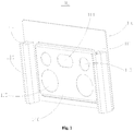
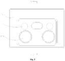
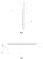
- Fig. 1 to Fig. 5 illustrate a structure diagram of an end plate 100.
- the end plate 100 may include: a plate-shaped body portion 110 that has a first surface 111 and a second surface 112 disposed opposite to each other, wherein output electrode holes 113 are disposed on the body portion to enable output electrodes of the battery module to extend out from the output electrode holes 113; a connecting pillar 120 disposed on the first surface 111 and extending in a first direction (Z), wherein the connecting pillar 120 includes a connecting though-hole 121 passing through the connecting pillar 120 along the first direction (Z); and a vent hole 114 disposed on the body portion 110 for mounting a vent plate of the battery module.
- the output electrode holes 113 may be disposed on the end plate 100, which enables the output electrodes of the battery module to extend out from the output electrode holes 113.
- the connecting pillars 120 may be disposed on the first surface 111 of the end plate 100, and each connecting pillar 120 may be provided with a connecting though-hole 121, such that a plurality of battery modules may connect to each other through the connecting though-holes 121 of the connecting pillars 120 along the extending direction of the connecting pillars 120.
- the connecting pillars 120 may be disposed on the surface of the end plate 100 instead of being disposed on the body portion 110 of the end plate 100, the requirement regarding to the thickness of the end plate 100 is reduced, and the body portion 110 of the end plate 100 may be thinner, such that the weight of the battery module may be reduced, and the energy density of the battery module may be increased.
- the vent hole 114 may be disposed on the body portion so as to mount the vent plate of the battery module.
- the end plate 100 of the embodiment of the present disclosure has diversified functions, lighter weight, and simple structure.
- the manufacturing material of the end plate 100 is not limited herein, and in order to ensure the strength of the end plate 100, the end plate 100 may be made of an aluminum plate, a steel plate, an iron plate, and other materials.
- the output electrode holes 113 may be disposed in many ways.
- the number of the output electrode holes 113 may be two, and the two output electrode holes 113 may be distributed at intervals on the body portion 110 along the second direction (Y), wherein the second direction (Y) and the first direction (Z) may be perpendicular to each other.
- the two output electrode holes 113 allow the positive and negative output electrodes of the battery module to extend out, and the two output electrode holes 113 may be distributed at intervals on the body portion 110 along the second direction (Y), such that the influence to the strength of the end plate 100 caused by the output electrode holes 113 may be reduced as much as possible to ensure that the end plate 100 has sufficient strength.
- the end plate 100 may further include at least two mounting holes 115 for mounting a deformable plate of the battery module.
- the end plate 100 may further be provided with the mounting holes 115, and the deformable plate of the battery module may be fixed in the mounting holes 115 by means of welding or the like.
- the function of the end plate 100 may be further enriched so as to reduce the number of components in the battery module and simplify the structure of the battery module.
- the number of the mounting holes 115 may be two.
- the two mounting holes may be distributed at intervals along the second direction (Y), and the two mounting holes 115 and the two output electrode holes 113 may be disposed side by side at intervals along the first direction (Z).
- the number of the vent hole 114 may be one, and the vent hole 114 may be disposed between the two output electrode holes 113.
- the mounting holes 115 and the output electrode holes 113 may be disposed side by side along the first direction (Z), and in the battery module, the aperture of the mounting holes 115 of the deformable plate may be generally larger than the aperture of the output electrode holes 113. Therefore, the vent hole 114 may be disposed between the output electrode holes 113, such that the influence to the strength of the end plate 100 caused by the openings on the end plate 100 may be reduced.
- the end plate may be further provided with a plurality of positioning concave portions 130, wherein the positioning concave portion 130 may be formed by the second surface being concaved toward the first surface, and at least one of the mounting holes 115 and the vent hole 114 may be disposed on the positioning concave portion 130.
- the end plate 100 may be provided with the positioning concave portions 130 so as to facilitate the positioning of the vent plate and the deformable plate on the end plate 100, such that the vent plate or the deformable plate may be fixed to the vent hole 114 or the mounting holes 115.
- the end plate 100 further includes a convex portion 140 formed by the body portion 110 protruding in a direction from the second surface 112 to the first surface 111, wherein the output electrode holes 113 and the vent hole 114 may be disposed on the convex portion 140.
- the convex portion 140 With the convex portion 140 being disposed, the strength of the end plate 100 may be improved, and the positioning of the output electrode holes 113 and the vent hole 114 may be facilitated, and the forming of the end plate 100 may also be facilitated.
- the positioning concave portions 130 may also be disposed on the convex portion 140, such that the positioning of the positioning concave portions 130 may be facilitated, and the forming of the end plate 100 may also be facilitated.
- the number of the connecting pillars 120 is two, and the two connecting pillars 120 are distributed on both sides of the convex portion 140 along the second direction (Y). Accordingly, the two connecting pillars 120 are disposed on both sides of the convex portion 140, such that the strength of the end plate may be improved.
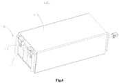
- a second embodiment of the present disclosure provides a housing 200 for a battery module
- the housing 200 may include: a barrel-shaped housing body 210 extending in a third direction (X), wherein the housing body 210 has a containing chamber 211 and two openings 212 connected with the containing chamber 211 and disposed opposite to each other along the third direction (X); the end plate 100 described in any of the above embodiments, wherein each of the openings 212 may be provided with the end plate 100, and the second surface 112 of the end plate 100 may be disposed close to the housing body 210; wherein the third direction (X) and the first direction (Z) may be perpendicular to each other.
- the housing 200 for the battery module may include a housing body 210 and at least two end plates 100.
- the housing body 210 may be in a barrel shape, which facilitates the assembly of the battery module.
- the housing 200 may also include the end plate 100 described in any of the above embodiments, and therefore may have the advantageous effects of any of the above embodiments, which will not be described herein again.
- the length of the housing body 210 in the third direction (X) is greater than the width of the housing body 210 in the second direction (Y), and the width of the housing body 210 is greater than the height of the housing body 210 in the first direction (Z).
- the height of the housing 200 in the first direction (Z) is small.
- a third embodiment of the present disclosure provides a battery module, including: the housing 200 described in any of the above embodiments; and a plurality of batteries 300 disposed side by side in the containing chamber 211 along the second direction (Y).
- the battery module may include the housing 200 described in any of the above embodiments, and therefore may have the advantageous effects of the housing 200 described in any of the above embodiments, which will not be described herein again.
- the battery 300 includes output terminals 310 disposed on at least one end of the two ends of the battery 300 along the third direction (X).
- the output terminals 310 of the battery 300 may be disposed on at least one end of the two ends of the battery 300 along the third direction (X)
- the output terminals 310 may not occupy the height in the first direction (Z) and may not affect the strength of the battery 300 in the first direction (Z).
- the battery module may also include a vent plate (not shown) disposed in the vent hole 114 of the end plate 100.
- the battery module may further include a deformable plate (not shown) disposed in the mounting hole 115 of the end plate 100.
- the battery module may further include an output component 500 including a connecting component 510 and an output pole 520, wherein the connecting component 510 may be provided with a connecting hole 511, and the output pole 520 may have a connecting portion 521 and a stop portion 522 along its extending direction, wherein the diameter of the connecting portion 521 matches with the output electrode hole 113 and the connecting hole 511 such that the output pole 520 may be able to pass through the output electrode hole 113 and nest in the connecting hole 511, and the diameter of the stop portion 522 may be greater than or equal to the diameter of the connecting portion 521 such that the connecting component 510 may be fixed to the end plate 100 through the output pole 520.
- the electrical connection between the battery module and external devices may be implemented via the connecting component 510, and the connecting component 510 may be fixed to the end plate 100 through the output pole 520.
- the diameter of the stop portion 522 may not be limited herein, and the diameter of the preferred stop portion 522 may be greater than the diameter of the connecting portion 521 such that the connecting component 510 may be fixed to the end plate 100 via the stop function of the stop portion 522.
- the battery module may further include an insulating separator 400 disposed between the batteries 300 and the end plate 100.
Landscapes
- Chemical & Material Sciences (AREA)
- Chemical Kinetics & Catalysis (AREA)
- Electrochemistry (AREA)
- General Chemical & Material Sciences (AREA)
- Engineering & Computer Science (AREA)
- Manufacturing & Machinery (AREA)
- Materials Engineering (AREA)
- Microelectronics & Electronic Packaging (AREA)
- Connection Of Batteries Or Terminals (AREA)
- Battery Mounting, Suspending (AREA)
- Gas Exhaust Devices For Batteries (AREA)
Claims (8)
- Plaque d'extrémité (100) pour un logement (200) d'un module de batteries, comprenant :une partie de corps en forme de plaque (110) qui a une première surface (111) et une deuxième surface (112) disposées en regard l'une de l'autre, où des trous d'électrode de sortie (113) sont disposés sur la partie de corps (110) pour permettre aux électrodes de sortie du module de batteries de s'étendre à partir des trous d'électrode de sortie (113) ; etun trou d'évent (114) disposé sur la partie de corps (110) pour monter une plaque d'évent du module de batteries ; caractérisée par :un montant de liaison (120) disposé sur la première surface (111) et s'étendant dans une première direction (Z), où le montant de liaison (120) comprend un trou traversant de liaison (121) traversant le montant de liaison (120) le long de la première direction (Z) ; etune partie convexe (140) formée par la partie de corps (110) faisant saillie dans une direction allant de la deuxième surface (112) vers la première surface (111), où les trous d'électrode de sortie (113) et le trou d'évent (114) sont disposés sur la partie convexe (140),où le nombre de montants de liaison (120) est égal à deux, et où en outre l'un des deux montants est distribué sur un premier côté de la partie convexe (140), dans la deuxième direction (Y), et l'autre des deux montants est distribué sur un deuxième côté de la partie convexe (140), dans la deuxième direction, moyennant quoi les directions (Y) et (Z) sont perpendiculaires l'une à l'autre.
- Plaque d'extrémité (100) selon la revendication 1, dans laquelle le nombre des trous d'électrode de sortie (113) est égal à deux, les deux trous d'électrode de sortie (113) sont distribués à certains intervalles sur la partie de corps (110) le long d'une deuxième direction (Y), où la deuxième direction (Y) et la première direction (Z) sont perpendiculaires l'une à l'autre, et le trou d'évent (114) est disposé entre les deux trous d'électrode de sortie (113) .
- Plaque d'extrémité (100) selon la revendication 2, comprenant en outre au moins deux trous de montage (115) disposés sur la partie de corps (110) pour monter une plaque déformable du module de batteries, où les au moins deux trous de montage (115) sont distribués à certains intervalles le long de la deuxième direction (Y), et les au moins deux trous de montage (115) et les deux trous d'électrode de sortie (113) sont disposés côte à côte à certains intervalles le long de la première direction (Z) .
- Plaque d'extrémité (100) selon la revendication 3, comprenant en outre une pluralité de parties concaves de positionnement (130), où les parties concaves de positionnement (130) sont formées par la deuxième surface (112) qui est concave vers la première surface (111), et les trous de montage (115) et le trou d'évent (114) sont disposés sur la partie concave de positionnement (130).
- Logement (200) pour module de batteries, comprenant :un corps de logement en forme de tonneau (210) s'étendant dans une troisième direction (X), où le corps de logement (210) a une chambre de confinement (211) et deux ouvertures (212) reliées à la chambre de confinement (211) et disposées en regard l'une de l'autre le long de la troisième direction (X) ;la plaque d'extrémité (100) selon l'une quelconque des revendications 1 à 4, où chacune des ouvertures (212) est pourvue de la plaque d'extrémité (100), et la deuxième surface (112) de la plaque d'extrémité (100) est disposée à proximité du corps de logement (210) ;où la troisième direction (X) et la première direction (Z) sont perpendiculaires l'une à l'autre.
- Module de batteries, comprenant :le logement (200) selon la revendication 5 ;une pluralité de batteries (300) disposées côte à côte dans la chambre de confinement (211) le long de la deuxième direction (Y).
- Module de batteries selon la revendication 6, dans lequel la batterie (300) comprend des bornes de sortie (310) disposées sur au moins une extrémité des deux extrémités de la batterie (300) le long de la troisième direction (X).
- Module de batteries selon la revendication 6, comprenant en outre :
un composant de sortie (500) comprenant un composant de liaison (510) et un pôle de sortie (520), où le composant de liaison (510) est pourvu d'un trou de liaison (511), et le pôle de sortie (520) a une partie de liaison (521) et une partie d'arrêt (522) le long de sa direction d'extension, où le diamètre de la partie de liaison (521) correspond à l'orifice du trou d'électrode de sortie (114) et du trou de liaison (511) de sorte que la partie de liaison (521) soit capable de traverser le trou d'électrode de sortie (114) et de s'emboîter dans le trou de liaison (511), et le diamètre de la partie d'arrêt (522) est supérieur ou égal au diamètre de la partie de liaison (521) de sorte que le composant de liaison (510) soit capable d'être fixé à la plaque d'extrémité (100) à travers le pôle de sortie (520).
Applications Claiming Priority (1)
| Application Number | Priority Date | Filing Date | Title |
|---|---|---|---|
| CN201820365930.0U CN208014772U (zh) | 2018-03-16 | 2018-03-16 | 端板、壳体及电池模组 |
Publications (2)
| Publication Number | Publication Date |
|---|---|
| EP3540814A1 EP3540814A1 (fr) | 2019-09-18 |
| EP3540814B1 true EP3540814B1 (fr) | 2020-04-29 |
Family
ID=63143078
Family Applications (1)
| Application Number | Title | Priority Date | Filing Date |
|---|---|---|---|
| EP18187077.5A Active EP3540814B1 (fr) | 2018-03-16 | 2018-08-02 | Plaque d'extrémité, boîtier et module de batterie |
Country Status (4)
| Country | Link |
|---|---|
| US (1) | US20190288252A1 (fr) |
| EP (1) | EP3540814B1 (fr) |
| JP (1) | JP6688841B2 (fr) |
| CN (1) | CN208014772U (fr) |
Families Citing this family (9)
| Publication number | Priority date | Publication date | Assignee | Title |
|---|---|---|---|---|
| CN209183610U (zh) | 2018-12-28 | 2019-07-30 | 宁德时代新能源科技股份有限公司 | 电池模组 |
| CN111384343B (zh) * | 2018-12-30 | 2024-09-13 | 宁德时代新能源科技股份有限公司 | 一种电池包 |
| KR102913987B1 (ko) | 2019-10-18 | 2026-01-15 | 주식회사 엘지에너지솔루션 | 전지 모듈 및 이을 포함하는 전지 팩 |
| KR102798544B1 (ko) * | 2020-04-01 | 2025-04-18 | 주식회사 엘지에너지솔루션 | 전지 모듈 및 이를 포함하는 전지 팩 |
| CN114389212A (zh) * | 2020-10-02 | 2022-04-22 | 张家港杰茂铝业有限公司 | 一种多孔型新能源汽车接线盒铝型材 |
| JP7600391B2 (ja) * | 2021-08-26 | 2024-12-16 | エルジー エナジー ソリューション リミテッド | 安全性を高めたバッテリーパック |
| JP7652914B2 (ja) * | 2021-12-16 | 2025-03-27 | エルジー エナジー ソリューション リミテッド | 安全性が向上したバッテリーモジュール |
| CN220692270U (zh) * | 2023-08-10 | 2024-03-29 | 蜂巢能源科技股份有限公司 | 模组连接结构及动力电池 |
| DE102024110229A1 (de) * | 2024-04-12 | 2025-10-16 | Audi Aktiengesellschaft | Traktionsbatterie für ein Kraftfahrzeug |
Citations (1)
| Publication number | Priority date | Publication date | Assignee | Title |
|---|---|---|---|---|
| EP3525255A1 (fr) * | 2018-02-07 | 2019-08-14 | Contemporary Amperex Technology Co., Limited | Module de batterie |
Family Cites Families (8)
| Publication number | Priority date | Publication date | Assignee | Title |
|---|---|---|---|---|
| JP2009021048A (ja) * | 2007-07-10 | 2009-01-29 | Panasonic Corp | 電源モジュール |
| US8852789B2 (en) * | 2010-11-04 | 2014-10-07 | Samsung Sdi Co., Ltd. | Battery module having battery cell holder |
| US8980457B2 (en) * | 2010-11-04 | 2015-03-17 | Samsung Sdi Co., Ltd. | Battery module |
| US8642206B2 (en) * | 2010-11-04 | 2014-02-04 | Samsung Sdi Co., Ltd. | Battery module |
| KR101447062B1 (ko) * | 2012-01-26 | 2014-11-03 | 주식회사 엘지화학 | 전지모듈 및 이를 포함하는 전지팩 |
| DE102012219784A1 (de) * | 2012-10-29 | 2014-04-30 | Lisa Dräxlmaier GmbH | Batteriemodul mit einem Gaskanal |
| US9537125B2 (en) * | 2013-06-27 | 2017-01-03 | Samsung Sdi Co., Ltd. | Battery module |
| JP6252776B2 (ja) * | 2014-05-07 | 2017-12-27 | 株式会社豊田自動織機 | 電池モジュール |
-
2018
- 2018-03-16 CN CN201820365930.0U patent/CN208014772U/zh active Active
- 2018-07-26 JP JP2018140780A patent/JP6688841B2/ja active Active
- 2018-08-02 EP EP18187077.5A patent/EP3540814B1/fr active Active
- 2018-08-04 US US16/055,058 patent/US20190288252A1/en not_active Abandoned
Patent Citations (1)
| Publication number | Priority date | Publication date | Assignee | Title |
|---|---|---|---|---|
| EP3525255A1 (fr) * | 2018-02-07 | 2019-08-14 | Contemporary Amperex Technology Co., Limited | Module de batterie |
Also Published As
| Publication number | Publication date |
|---|---|
| JP2019160772A (ja) | 2019-09-19 |
| JP6688841B2 (ja) | 2020-04-28 |
| CN208014772U (zh) | 2018-10-26 |
| US20190288252A1 (en) | 2019-09-19 |
| EP3540814A1 (fr) | 2019-09-18 |
Similar Documents
| Publication | Publication Date | Title |
|---|---|---|
| EP3540814B1 (fr) | Plaque d'extrémité, boîtier et module de batterie | |
| JP7743892B2 (ja) | 蓄電モジュール | |
| EP3109926B1 (fr) | Batterie rechargeable et bloc-batterie rechargeable | |
| EP3010072B1 (fr) | Bloc-batterie | |
| US9337458B2 (en) | Battery module | |
| KR102444124B1 (ko) | 배터리 모듈 및 이를 포함하는 배터리 팩 | |
| EP2562842B1 (fr) | Module de batterie | |
| KR102475839B1 (ko) | 이차 전지 모듈 | |
| EP3349269B1 (fr) | Module de batterie, bloc-batterie et véhicule les comportant | |
| US9929427B2 (en) | Battery module having reinforcing barrier with metal member | |
| US11289762B2 (en) | Battery pack | |
| US20140295235A1 (en) | Battery module | |
| EP2793290A1 (fr) | Module de batterie | |
| US20140356664A1 (en) | Battery module | |
| EP4102625B1 (fr) | Ensemble couvercle supérieur, cellule de batterie, module de batterie | |
| KR101275785B1 (ko) | 이차 전지 | |
| EP2978061B1 (fr) | Batterie rechargeable de type poche et module de batterie rechargeable comprenant cette dernière | |
| EP2830121B1 (fr) | Batterie rechargeable | |
| JP6520156B2 (ja) | 蓄電装置及び蓄電装置モジュール | |
| CN217114627U (zh) | 电池和用电装置 | |
| KR102097083B1 (ko) | 배터리 팩 케이스 및 이를 포함하는 배터리 팩, 자동차 | |
| KR20210036902A (ko) | 이차 전지 모듈 및 이를 포함하는 이차 전지 팩 | |
| US9831486B2 (en) | Battery module | |
| KR102001105B1 (ko) | 이차 전지 | |
| KR102023733B1 (ko) | 배터리 셀, 이를 포함하는 배터리 모듈 및 배터리 팩 |
Legal Events
| Date | Code | Title | Description |
|---|---|---|---|
| PUAI | Public reference made under article 153(3) epc to a published international application that has entered the european phase |
Free format text: ORIGINAL CODE: 0009012 |
|
| STAA | Information on the status of an ep patent application or granted ep patent |
Free format text: STATUS: REQUEST FOR EXAMINATION WAS MADE |
|
| 17P | Request for examination filed |
Effective date: 20190613 |
|
| AK | Designated contracting states |
Kind code of ref document: A1 Designated state(s): AL AT BE BG CH CY CZ DE DK EE ES FI FR GB GR HR HU IE IS IT LI LT LU LV MC MK MT NL NO PL PT RO RS SE SI SK SM TR |
|
| AX | Request for extension of the european patent |
Extension state: BA ME |
|
| GRAP | Despatch of communication of intention to grant a patent |
Free format text: ORIGINAL CODE: EPIDOSNIGR1 |
|
| STAA | Information on the status of an ep patent application or granted ep patent |
Free format text: STATUS: GRANT OF PATENT IS INTENDED |
|
| INTG | Intention to grant announced |
Effective date: 20191023 |
|
| GRAJ | Information related to disapproval of communication of intention to grant by the applicant or resumption of examination proceedings by the epo deleted |
Free format text: ORIGINAL CODE: EPIDOSDIGR1 |
|
| STAA | Information on the status of an ep patent application or granted ep patent |
Free format text: STATUS: REQUEST FOR EXAMINATION WAS MADE |
|
| GRAP | Despatch of communication of intention to grant a patent |
Free format text: ORIGINAL CODE: EPIDOSNIGR1 |
|
| STAA | Information on the status of an ep patent application or granted ep patent |
Free format text: STATUS: GRANT OF PATENT IS INTENDED |
|
| INTC | Intention to grant announced (deleted) | ||
| INTG | Intention to grant announced |
Effective date: 20191219 |
|
| GRAS | Grant fee paid |
Free format text: ORIGINAL CODE: EPIDOSNIGR3 |
|
| GRAA | (expected) grant |
Free format text: ORIGINAL CODE: 0009210 |
|
| STAA | Information on the status of an ep patent application or granted ep patent |
Free format text: STATUS: THE PATENT HAS BEEN GRANTED |
|
| AK | Designated contracting states |
Kind code of ref document: B1 Designated state(s): AL AT BE BG CH CY CZ DE DK EE ES FI FR GB GR HR HU IE IS IT LI LT LU LV MC MK MT NL NO PL PT RO RS SE SI SK SM TR |
|
| REG | Reference to a national code |
Ref country code: GB Ref legal event code: FG4D |
|
| REG | Reference to a national code |
Ref country code: CH Ref legal event code: EP |
|
| REG | Reference to a national code |
Ref country code: AT Ref legal event code: REF Ref document number: 1264641 Country of ref document: AT Kind code of ref document: T Effective date: 20200515 |
|
| REG | Reference to a national code |
Ref country code: DE Ref legal event code: R096 Ref document number: 602018004139 Country of ref document: DE |
|
| REG | Reference to a national code |
Ref country code: IE Ref legal event code: FG4D |
|
| REG | Reference to a national code |
Ref country code: NL Ref legal event code: MP Effective date: 20200429 |
|
| REG | Reference to a national code |
Ref country code: LT Ref legal event code: MG4D |
|
| PG25 | Lapsed in a contracting state [announced via postgrant information from national office to epo] |
Ref country code: NO Free format text: LAPSE BECAUSE OF FAILURE TO SUBMIT A TRANSLATION OF THE DESCRIPTION OR TO PAY THE FEE WITHIN THE PRESCRIBED TIME-LIMIT Effective date: 20200729 Ref country code: LT Free format text: LAPSE BECAUSE OF FAILURE TO SUBMIT A TRANSLATION OF THE DESCRIPTION OR TO PAY THE FEE WITHIN THE PRESCRIBED TIME-LIMIT Effective date: 20200429 Ref country code: PT Free format text: LAPSE BECAUSE OF FAILURE TO SUBMIT A TRANSLATION OF THE DESCRIPTION OR TO PAY THE FEE WITHIN THE PRESCRIBED TIME-LIMIT Effective date: 20200831 Ref country code: GR Free format text: LAPSE BECAUSE OF FAILURE TO SUBMIT A TRANSLATION OF THE DESCRIPTION OR TO PAY THE FEE WITHIN THE PRESCRIBED TIME-LIMIT Effective date: 20200730 Ref country code: SE Free format text: LAPSE BECAUSE OF FAILURE TO SUBMIT A TRANSLATION OF THE DESCRIPTION OR TO PAY THE FEE WITHIN THE PRESCRIBED TIME-LIMIT Effective date: 20200429 Ref country code: IS Free format text: LAPSE BECAUSE OF FAILURE TO SUBMIT A TRANSLATION OF THE DESCRIPTION OR TO PAY THE FEE WITHIN THE PRESCRIBED TIME-LIMIT Effective date: 20200829 Ref country code: FI Free format text: LAPSE BECAUSE OF FAILURE TO SUBMIT A TRANSLATION OF THE DESCRIPTION OR TO PAY THE FEE WITHIN THE PRESCRIBED TIME-LIMIT Effective date: 20200429 |
|
| REG | Reference to a national code |
Ref country code: AT Ref legal event code: MK05 Ref document number: 1264641 Country of ref document: AT Kind code of ref document: T Effective date: 20200429 |
|
| REG | Reference to a national code |
Ref country code: DE Ref legal event code: R079 Ref document number: 602018004139 Country of ref document: DE Free format text: PREVIOUS MAIN CLASS: H01M0002100000 Ipc: H01M0050200000 |
|
| PG25 | Lapsed in a contracting state [announced via postgrant information from national office to epo] |
Ref country code: RS Free format text: LAPSE BECAUSE OF FAILURE TO SUBMIT A TRANSLATION OF THE DESCRIPTION OR TO PAY THE FEE WITHIN THE PRESCRIBED TIME-LIMIT Effective date: 20200429 Ref country code: HR Free format text: LAPSE BECAUSE OF FAILURE TO SUBMIT A TRANSLATION OF THE DESCRIPTION OR TO PAY THE FEE WITHIN THE PRESCRIBED TIME-LIMIT Effective date: 20200429 Ref country code: LV Free format text: LAPSE BECAUSE OF FAILURE TO SUBMIT A TRANSLATION OF THE DESCRIPTION OR TO PAY THE FEE WITHIN THE PRESCRIBED TIME-LIMIT Effective date: 20200429 Ref country code: BG Free format text: LAPSE BECAUSE OF FAILURE TO SUBMIT A TRANSLATION OF THE DESCRIPTION OR TO PAY THE FEE WITHIN THE PRESCRIBED TIME-LIMIT Effective date: 20200729 |
|
| PG25 | Lapsed in a contracting state [announced via postgrant information from national office to epo] |
Ref country code: NL Free format text: LAPSE BECAUSE OF FAILURE TO SUBMIT A TRANSLATION OF THE DESCRIPTION OR TO PAY THE FEE WITHIN THE PRESCRIBED TIME-LIMIT Effective date: 20200429 Ref country code: AL Free format text: LAPSE BECAUSE OF FAILURE TO SUBMIT A TRANSLATION OF THE DESCRIPTION OR TO PAY THE FEE WITHIN THE PRESCRIBED TIME-LIMIT Effective date: 20200429 |
|
| PG25 | Lapsed in a contracting state [announced via postgrant information from national office to epo] |
Ref country code: CZ Free format text: LAPSE BECAUSE OF FAILURE TO SUBMIT A TRANSLATION OF THE DESCRIPTION OR TO PAY THE FEE WITHIN THE PRESCRIBED TIME-LIMIT Effective date: 20200429 Ref country code: RO Free format text: LAPSE BECAUSE OF FAILURE TO SUBMIT A TRANSLATION OF THE DESCRIPTION OR TO PAY THE FEE WITHIN THE PRESCRIBED TIME-LIMIT Effective date: 20200429 Ref country code: ES Free format text: LAPSE BECAUSE OF FAILURE TO SUBMIT A TRANSLATION OF THE DESCRIPTION OR TO PAY THE FEE WITHIN THE PRESCRIBED TIME-LIMIT Effective date: 20200429 Ref country code: SM Free format text: LAPSE BECAUSE OF FAILURE TO SUBMIT A TRANSLATION OF THE DESCRIPTION OR TO PAY THE FEE WITHIN THE PRESCRIBED TIME-LIMIT Effective date: 20200429 Ref country code: EE Free format text: LAPSE BECAUSE OF FAILURE TO SUBMIT A TRANSLATION OF THE DESCRIPTION OR TO PAY THE FEE WITHIN THE PRESCRIBED TIME-LIMIT Effective date: 20200429 Ref country code: AT Free format text: LAPSE BECAUSE OF FAILURE TO SUBMIT A TRANSLATION OF THE DESCRIPTION OR TO PAY THE FEE WITHIN THE PRESCRIBED TIME-LIMIT Effective date: 20200429 Ref country code: DK Free format text: LAPSE BECAUSE OF FAILURE TO SUBMIT A TRANSLATION OF THE DESCRIPTION OR TO PAY THE FEE WITHIN THE PRESCRIBED TIME-LIMIT Effective date: 20200429 Ref country code: IT Free format text: LAPSE BECAUSE OF FAILURE TO SUBMIT A TRANSLATION OF THE DESCRIPTION OR TO PAY THE FEE WITHIN THE PRESCRIBED TIME-LIMIT Effective date: 20200429 |
|
| REG | Reference to a national code |
Ref country code: DE Ref legal event code: R097 Ref document number: 602018004139 Country of ref document: DE |
|
| PG25 | Lapsed in a contracting state [announced via postgrant information from national office to epo] |
Ref country code: PL Free format text: LAPSE BECAUSE OF FAILURE TO SUBMIT A TRANSLATION OF THE DESCRIPTION OR TO PAY THE FEE WITHIN THE PRESCRIBED TIME-LIMIT Effective date: 20200429 Ref country code: SK Free format text: LAPSE BECAUSE OF FAILURE TO SUBMIT A TRANSLATION OF THE DESCRIPTION OR TO PAY THE FEE WITHIN THE PRESCRIBED TIME-LIMIT Effective date: 20200429 |
|
| PLBE | No opposition filed within time limit |
Free format text: ORIGINAL CODE: 0009261 |
|
| STAA | Information on the status of an ep patent application or granted ep patent |
Free format text: STATUS: NO OPPOSITION FILED WITHIN TIME LIMIT |
|
| PG25 | Lapsed in a contracting state [announced via postgrant information from national office to epo] |
Ref country code: MC Free format text: LAPSE BECAUSE OF FAILURE TO SUBMIT A TRANSLATION OF THE DESCRIPTION OR TO PAY THE FEE WITHIN THE PRESCRIBED TIME-LIMIT Effective date: 20200429 |
|
| 26N | No opposition filed |
Effective date: 20210201 |
|
| PG25 | Lapsed in a contracting state [announced via postgrant information from national office to epo] |
Ref country code: LU Free format text: LAPSE BECAUSE OF NON-PAYMENT OF DUE FEES Effective date: 20200802 |
|
| REG | Reference to a national code |
Ref country code: BE Ref legal event code: MM Effective date: 20200831 |
|
| PG25 | Lapsed in a contracting state [announced via postgrant information from national office to epo] |
Ref country code: BE Free format text: LAPSE BECAUSE OF NON-PAYMENT OF DUE FEES Effective date: 20200831 Ref country code: IE Free format text: LAPSE BECAUSE OF NON-PAYMENT OF DUE FEES Effective date: 20200802 |
|
| REG | Reference to a national code |
Ref country code: CH Ref legal event code: PL |
|
| PG25 | Lapsed in a contracting state [announced via postgrant information from national office to epo] |
Ref country code: LI Free format text: LAPSE BECAUSE OF NON-PAYMENT OF DUE FEES Effective date: 20210831 Ref country code: CH Free format text: LAPSE BECAUSE OF NON-PAYMENT OF DUE FEES Effective date: 20210831 |
|
| PG25 | Lapsed in a contracting state [announced via postgrant information from national office to epo] |
Ref country code: TR Free format text: LAPSE BECAUSE OF FAILURE TO SUBMIT A TRANSLATION OF THE DESCRIPTION OR TO PAY THE FEE WITHIN THE PRESCRIBED TIME-LIMIT Effective date: 20200429 Ref country code: MT Free format text: LAPSE BECAUSE OF FAILURE TO SUBMIT A TRANSLATION OF THE DESCRIPTION OR TO PAY THE FEE WITHIN THE PRESCRIBED TIME-LIMIT Effective date: 20200429 Ref country code: CY Free format text: LAPSE BECAUSE OF FAILURE TO SUBMIT A TRANSLATION OF THE DESCRIPTION OR TO PAY THE FEE WITHIN THE PRESCRIBED TIME-LIMIT Effective date: 20200429 |
|
| PG25 | Lapsed in a contracting state [announced via postgrant information from national office to epo] |
Ref country code: MK Free format text: LAPSE BECAUSE OF FAILURE TO SUBMIT A TRANSLATION OF THE DESCRIPTION OR TO PAY THE FEE WITHIN THE PRESCRIBED TIME-LIMIT Effective date: 20200429 |
|
| P01 | Opt-out of the competence of the unified patent court (upc) registered |
Effective date: 20230516 |
|
| PG25 | Lapsed in a contracting state [announced via postgrant information from national office to epo] |
Ref country code: SI Free format text: LAPSE BECAUSE OF FAILURE TO SUBMIT A TRANSLATION OF THE DESCRIPTION OR TO PAY THE FEE WITHIN THE PRESCRIBED TIME-LIMIT Effective date: 20200429 |
|
| REG | Reference to a national code |
Ref country code: GB Ref legal event code: 732E Free format text: REGISTERED BETWEEN 20240815 AND 20240821 |
|
| REG | Reference to a national code |
Ref country code: DE Ref legal event code: R081 Ref document number: 602018004139 Country of ref document: DE Owner name: CONTEMPORARY AMPEREX TECHNOLOGY (HONG KONG) LI, HK Free format text: FORMER OWNER: CONTEMPORARY AMPEREX TECHNOLOGY CO., LTD., NINGDE CITY, FUJIAN, CN |
|
| PGFP | Annual fee paid to national office [announced via postgrant information from national office to epo] |
Ref country code: GB Payment date: 20250612 Year of fee payment: 8 |
|
| PGFP | Annual fee paid to national office [announced via postgrant information from national office to epo] |
Ref country code: FR Payment date: 20250610 Year of fee payment: 8 |
|
| PGFP | Annual fee paid to national office [announced via postgrant information from national office to epo] |
Ref country code: DE Payment date: 20250611 Year of fee payment: 8 |