EP3540858A1 - Structure de raccordement de câblage et procédé de fabrication de structure de raccordement de câblage - Google Patents
Structure de raccordement de câblage et procédé de fabrication de structure de raccordement de câblage Download PDFInfo
- Publication number
- EP3540858A1 EP3540858A1 EP19162113.5A EP19162113A EP3540858A1 EP 3540858 A1 EP3540858 A1 EP 3540858A1 EP 19162113 A EP19162113 A EP 19162113A EP 3540858 A1 EP3540858 A1 EP 3540858A1
- Authority
- EP
- European Patent Office
- Prior art keywords
- cable
- holder
- round
- flat cable
- flat
- Prior art date
- Legal status (The legal status is an assumption and is not a legal conclusion. Google has not performed a legal analysis and makes no representation as to the accuracy of the status listed.)
- Withdrawn
Links
- 238000004519 manufacturing process Methods 0.000 title claims description 18
- 238000000034 method Methods 0.000 title 1
- 229920005989 resin Polymers 0.000 claims abstract description 35
- 239000011347 resin Substances 0.000 claims abstract description 35
- 239000004020 conductor Substances 0.000 claims description 42
- 238000000465 moulding Methods 0.000 claims description 10
- 239000000853 adhesive Substances 0.000 claims description 6
- 230000001070 adhesive effect Effects 0.000 claims description 6
- 229920001169 thermoplastic Polymers 0.000 claims description 6
- 239000004416 thermosoftening plastic Substances 0.000 claims description 6
- 238000010438 heat treatment Methods 0.000 claims description 3
- 229920005992 thermoplastic resin Polymers 0.000 claims 1
- 238000003466 welding Methods 0.000 description 31
- 238000005192 partition Methods 0.000 description 19
- 239000004831 Hot glue Substances 0.000 description 14
- 238000003780 insertion Methods 0.000 description 5
- 230000037431 insertion Effects 0.000 description 5
- 230000002093 peripheral effect Effects 0.000 description 5
- 210000000078 claw Anatomy 0.000 description 3
- 239000011810 insulating material Substances 0.000 description 3
- 238000005452 bending Methods 0.000 description 1
- 230000015572 biosynthetic process Effects 0.000 description 1
- 239000000470 constituent Substances 0.000 description 1
- 238000001816 cooling Methods 0.000 description 1
- 238000005516 engineering process Methods 0.000 description 1
- 239000012943 hotmelt Substances 0.000 description 1
- 238000005304 joining Methods 0.000 description 1
- 230000014759 maintenance of location Effects 0.000 description 1
- 239000000155 melt Substances 0.000 description 1
Images









Classifications
-
- H—ELECTRICITY
- H01—ELECTRIC ELEMENTS
- H01R—ELECTRICALLY-CONDUCTIVE CONNECTIONS; STRUCTURAL ASSOCIATIONS OF A PLURALITY OF MUTUALLY-INSULATED ELECTRICAL CONNECTING ELEMENTS; COUPLING DEVICES; CURRENT COLLECTORS
- H01R13/00—Details of coupling devices of the kinds covered by groups H01R12/70 or H01R24/00 - H01R33/00
- H01R13/46—Bases; Cases
- H01R13/52—Dustproof, splashproof, drip-proof, waterproof, or flameproof cases
- H01R13/5205—Sealing means between cable and housing, e.g. grommet
-
- H—ELECTRICITY
- H01—ELECTRIC ELEMENTS
- H01R—ELECTRICALLY-CONDUCTIVE CONNECTIONS; STRUCTURAL ASSOCIATIONS OF A PLURALITY OF MUTUALLY-INSULATED ELECTRICAL CONNECTING ELEMENTS; COUPLING DEVICES; CURRENT COLLECTORS
- H01R12/00—Structural associations of a plurality of mutually-insulated electrical connecting elements, specially adapted for printed circuits, e.g. printed circuit boards [PCB], flat or ribbon cables, or like generally planar structures, e.g. terminal strips, terminal blocks; Coupling devices specially adapted for printed circuits, flat or ribbon cables, or like generally planar structures; Terminals specially adapted for contact with, or insertion into, printed circuits, flat or ribbon cables, or like generally planar structures
- H01R12/50—Fixed connections
- H01R12/59—Fixed connections for flexible printed circuits, flat or ribbon cables or like structures
- H01R12/63—Fixed connections for flexible printed circuits, flat or ribbon cables or like structures connecting to another shape cable
-
- H—ELECTRICITY
- H01—ELECTRIC ELEMENTS
- H01R—ELECTRICALLY-CONDUCTIVE CONNECTIONS; STRUCTURAL ASSOCIATIONS OF A PLURALITY OF MUTUALLY-INSULATED ELECTRICAL CONNECTING ELEMENTS; COUPLING DEVICES; CURRENT COLLECTORS
- H01R4/00—Electrically-conductive connections between two or more conductive members in direct contact, i.e. touching one another; Means for effecting or maintaining such contact; Electrically-conductive connections having two or more spaced connecting locations for conductors and using contact members penetrating insulation
- H01R4/02—Soldered or welded connections
- H01R4/021—Soldered or welded connections between two or more cables or wires
-
- H—ELECTRICITY
- H01—ELECTRIC ELEMENTS
- H01R—ELECTRICALLY-CONDUCTIVE CONNECTIONS; STRUCTURAL ASSOCIATIONS OF A PLURALITY OF MUTUALLY-INSULATED ELECTRICAL CONNECTING ELEMENTS; COUPLING DEVICES; CURRENT COLLECTORS
- H01R4/00—Electrically-conductive connections between two or more conductive members in direct contact, i.e. touching one another; Means for effecting or maintaining such contact; Electrically-conductive connections having two or more spaced connecting locations for conductors and using contact members penetrating insulation
- H01R4/02—Soldered or welded connections
- H01R4/027—Soldered or welded connections comprising means for positioning or holding the parts to be soldered or welded
-
- H—ELECTRICITY
- H01—ELECTRIC ELEMENTS
- H01R—ELECTRICALLY-CONDUCTIVE CONNECTIONS; STRUCTURAL ASSOCIATIONS OF A PLURALITY OF MUTUALLY-INSULATED ELECTRICAL CONNECTING ELEMENTS; COUPLING DEVICES; CURRENT COLLECTORS
- H01R4/00—Electrically-conductive connections between two or more conductive members in direct contact, i.e. touching one another; Means for effecting or maintaining such contact; Electrically-conductive connections having two or more spaced connecting locations for conductors and using contact members penetrating insulation
- H01R4/70—Insulation of connections
-
- H—ELECTRICITY
- H01—ELECTRIC ELEMENTS
- H01R—ELECTRICALLY-CONDUCTIVE CONNECTIONS; STRUCTURAL ASSOCIATIONS OF A PLURALITY OF MUTUALLY-INSULATED ELECTRICAL CONNECTING ELEMENTS; COUPLING DEVICES; CURRENT COLLECTORS
- H01R4/00—Electrically-conductive connections between two or more conductive members in direct contact, i.e. touching one another; Means for effecting or maintaining such contact; Electrically-conductive connections having two or more spaced connecting locations for conductors and using contact members penetrating insulation
- H01R4/70—Insulation of connections
- H01R4/72—Insulation of connections using a heat shrinking insulating sleeve
-
- H—ELECTRICITY
- H01—ELECTRIC ELEMENTS
- H01R—ELECTRICALLY-CONDUCTIVE CONNECTIONS; STRUCTURAL ASSOCIATIONS OF A PLURALITY OF MUTUALLY-INSULATED ELECTRICAL CONNECTING ELEMENTS; COUPLING DEVICES; CURRENT COLLECTORS
- H01R43/00—Apparatus or processes specially adapted for manufacturing, assembling, maintaining, or repairing of line connectors or current collectors or for joining electric conductors
- H01R43/005—Apparatus or processes specially adapted for manufacturing, assembling, maintaining, or repairing of line connectors or current collectors or for joining electric conductors for making dustproof, splashproof, drip-proof, waterproof, or flameproof connection, coupling, or casing
-
- H—ELECTRICITY
- H01—ELECTRIC ELEMENTS
- H01R—ELECTRICALLY-CONDUCTIVE CONNECTIONS; STRUCTURAL ASSOCIATIONS OF A PLURALITY OF MUTUALLY-INSULATED ELECTRICAL CONNECTING ELEMENTS; COUPLING DEVICES; CURRENT COLLECTORS
- H01R43/00—Apparatus or processes specially adapted for manufacturing, assembling, maintaining, or repairing of line connectors or current collectors or for joining electric conductors
- H01R43/02—Apparatus or processes specially adapted for manufacturing, assembling, maintaining, or repairing of line connectors or current collectors or for joining electric conductors for soldered or welded connections
- H01R43/0207—Ultrasonic-, H.F.-, cold- or impact welding
-
- H—ELECTRICITY
- H01—ELECTRIC ELEMENTS
- H01R—ELECTRICALLY-CONDUCTIVE CONNECTIONS; STRUCTURAL ASSOCIATIONS OF A PLURALITY OF MUTUALLY-INSULATED ELECTRICAL CONNECTING ELEMENTS; COUPLING DEVICES; CURRENT COLLECTORS
- H01R43/00—Apparatus or processes specially adapted for manufacturing, assembling, maintaining, or repairing of line connectors or current collectors or for joining electric conductors
- H01R43/20—Apparatus or processes specially adapted for manufacturing, assembling, maintaining, or repairing of line connectors or current collectors or for joining electric conductors for assembling or disassembling contact members with insulating base, case or sleeve
- H01R43/24—Assembling by moulding on contact members
Definitions
- the present application relates to a cable connection structure for connecting a round cable and a flat cable and a manufacturing method of the cable connection structure.
- Such a conventional cable connection structure is in FIG. 19 shown.
- the conventional cable connection structure includes a holder 50, a plurality of round cables W1 held by the holder 50, a flat cable W2 held by the holder 50, and a mold resin portion 51 covering the outer periphery of the holder 50.
- the plurality of round cables W1 and the flat cable W2 held by the bracket 50 overlap at their end portions and are pulled out in opposite directions.
- Core wires (not shown) at the end portions of the round cables W1 and conductors (not shown) at an end portion of the flat cable W2 are connected to each other by connection portions 53 formed by ultrasonic welding or the like.
- the mold resin portion 51 collectively covers the holder 50 and the round cables W1 and the flat cable W2 pulled out of the holder 50. Accordingly, the portion having the connection portions 53 is waterproof by the mold resin portion 51.
- the core wires (not shown) of the round cables W1 and the conductors (not shown) of the flat cable W2 are connected to an ultrasonic welding apparatus 30 by ultrasonic welding, for example, as shown in FIG FIG. 20 shown.
- the ultrasonic welding apparatus 30 includes an anvil 34 that places the holder 50 in a positioned state, and a horn 33 that receives ultrasonic vibrations (in the direction of arrow in FIG FIG. 10 ) to the position in which the core wires (not shown) of the round cables W1 and the conductors (not shown) of the flat cable W2 overlap.
- the horn 33 is at the distal end of an arm portion 32 whose base end portion is supported by a device main body 31.
- the round cables W1 from the ultrasonic welder 30 and the flat cable W2 must be laid in the space between the horn 33 and the device main body 31 in some cases become.
- the harness (not shown) may not be inserted into the space between the horn 33 and the device main body 31.
- the flat cable W2 has excellent flexibility in the direction of bending the flat surface, it can hardly be bent in the direction orthogonal to the flat surface (transverse direction). Therefore, there is a problem that it is difficult to perform the ultrasonic welding when the ribbon cable W2 is sufficiently longer than the distance between the horn 33 and the device main body 31. A similar problem exists in a connection device other than the ultrasonic welding device 30.
- the present application has been conceived to solve the above-described problem, and an object of the present application is to provide a cable connection structure and a manufacturing method of the cable connection structure that can be manufactured with a connection device such as an ultrasonic welding device regardless of the length of a flat cable.
- a cable connecting structure comprises: a round cable having a round cross section and having a core wire and a round insulating jacket covering the outer periphery of the core wire; a flat cable having a cross section in a flat rectangular shape, comprising a tabular conductor and a flat insulating jacket covering the conductor; a holder that holds the end portion of the round cable and the end portion of the flat cable and pulls the round cable and the flat cable in the same direction in an overlapping state; a connecting portion in which the core wire exposed from an end portion of the round cable and the conductor exposed from an end portion of the flat cable held by the holder are connected to each other; and a waterproof outer portion that covers the outer circumference of the holder and the outer circumference of the round cable and the flat cable pulled out of the holder together.
- a manufacturing method of a cable connecting structure includes: a cable adjusting step for holding, in a state in which a round cable and a flat cable in an overlapping state are pulled out in a same direction, the end portion of the round cable and the end portion of the flat cable in FIG a holder; a connecting step of connecting a core wire exposed from the end portion of the round cable held by the holder and a conductor exposed from the end portion of the flat cable held by the holder; and an outer forming step of forming a waterproof outer portion with an insulating resin covering the holder, the round cable pulled out of the holder, and the flat cable pulled out of the holder.
- the round cable and the flat cable are pulled out of the holder in the same direction, whereby it is connected to a connecting device such as an ultrasonic welder, regardless of a length of the flat cable can be made.
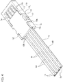
- a cable connection structure 3A includes a plurality of round cables W1, a flat cable W2, a holder 10 for holding end portions of the plurality of round cables W1 and the end portion of the flat cable W2, connection portions 20 in each of which a core wire 1a of each of the round cables W1 and a corresponding conductor 2a of the flat cable W2, and a mold resin portion 21 which is a waterproof outer portion covering an outer periphery of the holder 10.
- Each of the round cables W1 has a round cross section and includes the core wire 1a and an insulating jacket 1b covering the outer periphery of the core wire 1a.
- the core wire 1a is exposed from the insulating jacket 1b at an end portion of each of the round cables W1.
- the flat cable W2 has a cross section in a flat rectangular shape and includes a plurality of spaced-apart tabular conductors 2a and an insulating jacket 2b which covers the plurality of tabular conductors 2a together. Each of the conductors 2a is exposed from the insulating jacket 2b at an end portion of the flat cable W2.
- the holder 10 includes a round cable holder 11 for holding the end portions of the round cables W1 and a flat cable holder 15 for holding the end portion of the flat cable W2.
- the round cable holder 11 is formed of an insulating material. As in FIG. 2 1, the round cable holder 11 includes a round cable holder main body 12 in which a plurality of round cable arrangement grooves 12b partitioned by partition walls 12a are formed in parallel with each other, and a pair of locking frames 13 formed from the side end portions of the round cable holder main body 12 stand out. Each of the upper surfaces of the partition walls 12a of the main body 12 of the round cable holder is a stopper surface. Each of the round cables W1 is arranged in the round cable arrangement groove 12b so that the core wire 1a exposed at the end portion protrudes from the round cable holder 11.
- the flat cable holder 15 is formed of an insulating material. As in the FIGs. 3A and 3B 1, the flat cable holder 15 includes a flat cable holder main body 16 in which a flat cable assembly chamber 16a is formed, and a pair of locking claws 17 provided on surfaces exposed through cutouts 16b of the flat cable holder main body 16. The distal end side of the flat cable assembly chamber 16a of the flat cable holder main body 16 in the transverse direction is partitioned by a plurality of partition walls 16c. An upper surface of a side wall 16d of the main body 16 of the flat cable holder is a flush surface.
- the divided by the partition 16c portion of the flat cable assembly chamber 16a is opened to the outside in the state of the holder 10 in which the round cable holder 11 and the flat cable holder 15 are interconnected.
- a horn 33 of an ultrasonic welding apparatus 30 is inserted from the opened portion to the outside of the holder 10.
- On the rear side of the main body 16 of the flat cable holder there are formed a plurality of through holes 16e opened to the position of the flat cable assembly chamber 16a divided by the partition wall 16c.
- an anvil 34 of the ultrasonic welding apparatus 30 is inserted from the through hole 16e.
- the flat cable W2 is disposed in the flat cable assembly chamber 16a so that the respective conductors 2a exposed at the end portion of the flat cable W2 are positioned at the respective portions, which are separated by the partition walls 16c.
- the round cable holder 11 and the flat cable holder 15 are connected to each other by arranging the upper surfaces of the partition walls 12a of the round cable main body 12 and a surface of the flat cable W2 in the flat cable assembly chamber 16a. Accordingly, the round cable holder 11 and the flat cable holder 15 are connected to each other so that the round cable W1 from the round cable holder 11 and the flat cable W2 from the flat cable holder 15 overlap and are pulled out in the same direction. Furthermore, the end portions of the round cables W1 and the end portion of the flat cable W2 are overlapped and exposed to the outside.
- the mold resin portion 21 is formed of an insulating resin.
- the mold resin portion 21 collectively and gaplessly covers the outer exposed surface of the round cable holder 11, the outer exposed surface of the flat cable holder 15, the outer periphery of each of the round cables W1 pulled out of the round cable holder 11, and the outer periphery of the flat cable W2 pulled out of the flat cable holder 15.
- the molding resin according to the first embodiment is fixedly and gap-free on the outer peripheral surface of each of the round cables W1 and the outer peripheral surface of the flat cable W2 at the positions of the round cable W1 pulled outward from the mold resin portion 21 and the position of the mold resin portion 21 as well attached outside pulled out flat cable W2, whereby the waterproof property of the connecting portion 20 is secured.
- the holder 10 includes the round cable holder 11 and the flat cable holder 15, and the round cables W1 are held by the round cable holder 11 while the flat cable W2 is held by the flat cable holder 15, whereby good workability of the holding cables with the holder 10 is achieved.
- the manufacturing method of the cable connecting structure 3A is performed in the order of a cable adjusting step, a joining step and a mold resin inserting step which is an outer forming step.
- the cable adjustment step includes a cable retention step and a holder combination step.
- the manufacturing method of the cable connecting structure 3A will be described in order.
- the round cables W1 are held in the round cable holder 11 and the flat cable W2 is held in the flat cable holder 15.
- a plurality of round cables W1 are arranged in the round cable arrangement grooves 12b of the round cable holder 11 so that the core wire 1a exposed from the end portion of each of the round cables W1 protrudes from the round cable holder 11 (round cable holding step).
- the flat cable W2, as in the FIGS. 3A and 3B is disposed in the flat cable assembly chamber 16a so that the conductors 2a exposed from the end portion of the flat cable W2 are positioned in the flat cable arrangement chamber 16a separated by the partition walls 16c (flat cable holding step).
- the round cable holding step with respect to the round cable holder 11 and the flat cable holding step with respect to the flat cable holder 15 may not be performed in any specific order and at the same time.
- the round cable holder 11 and the flat cable holder 15 are connected to each other.
- the upper surfaces of the partition walls 12a of the round cable main body 12 and the surface of the flat cable W2 disposed in the flat cable assembly chamber 16a abut each other, and the locking claws 17 are fixed to the latch frame 13.
- the core wires 1a exposed from the end portions of the plurality of round cables W1 and the conductors 2a exposed from the end portion of the flat cable W2 are arranged to extend overlap each other and exposed to the outside.
- the round cables W1 and the flat cable W2 from the combined round cable holder 11 and the flat cable holder 15 are pulled out to overlap in the same direction.
- the round cables W1 and the flat cable W2 are electrically connected to the ultrasonic welding device 30 by ultrasonic welding.
- the ultrasonic welding apparatus 30 includes the anvil 34 and the horn 33 at the location facing the anvil 34.
- the horn 33 is provided at the distal end of an arm portion 32 whose base end portion is supported by a device main body 31.
- the round cables W1 and the flat cable W2 pulled out of the combined round cable holder 11 and the flat cable holder 15 are not arranged in the space between the horn 33 and the device main body 31, but in the clearance on the opposite side so that the combined round cable holder 11 and the Flat cable holder 15 are positioned on the anvil 34.
- an ultrasonic vibration (in the arrow direction in FIG. 5 ) is applied to the position where the core wires 1a of the round cables W1 and the conductors 2a of the flat cable W2 overlap while pressure is applied.
- the core wires 1a of the round cables W1 and the conductors 2a of the flat cable W2 through the Ultrasonic welding connected.
- the insertion resin step the insertion of resin molding with the round cable holder 11, the flat cable holder 15, the round cables W1 withdrawn from the round cable holder 11, and the flat cable W2 serving as inserts is performed from the flat cable holder 15, and the mold resin portion 21 is formed.
- the cable connection structure 3A as shown in FIGS FIGS. 1A and 1B shown.
- the cable connection structure 3A includes the round cables W1 each having a round cross section and having the core wire 1a and the round insulating jacket 1b covering the outer periphery of the core wire 1a, the flat cable W2 having a cross section in a flat rectangular shape Form and the tabular conductor 2a and the conductor 2a covering flat sheath 2b, the holder 10, which holds the end portions of the round cable W1 and the end portion of the flat cable W2 and the round cable W1 and the flat cable W2 in the same direction in an overlapping state wherein the connecting portions 20 in which the core wires 1a exposed from the end portions of the round cables W1 and the conductors 2a exposed from the end portion of the flat cable W2 held by the holder 10 are connected, and the mold resin portion 21 as the waterproof outer portion collectively surrounds the outer circumference of the Hal ters 10 and the outer circumference of the round cable W1 and the pulled out of the holder 10 flat cable W2 covers.
- the round cables W1 and the flat cable W2 are pulled out in the same direction from the holder 10, thereby providing a connection device such as the ultrasonic welding device 30 regardless of a length of the flat cable W2 can be produced.
- FIGs. 6A to 8B illustrate a second embodiment.
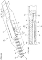
- a cable connection structure 3B according to the second embodiment differs from the cable connection structure 3A according to the first embodiment in the following points. That is, like in the FIGs. 6A and 6B That is, in the cable connecting structure 3B according to the second embodiment, a flat cable W2 is bent to be guided in a direction other than the withdrawn direction by a flat cable holder 15, namely in the diametrically opposite pulled-out direction. The round cables W1 and the flat cable W2 are pulled out of a mold resin portion 21 in different directions, particularly in the diametrically opposite directions.
- molding resin is fixed and gap-free on the outer circumferential surface of each of the round cables W1 and the outer peripheral surface of the flat cable W2 at the position of the round cable W1 pulled outward from the mold resin portion 21 and the position also of the mold resin portion 21 fastened outwardly flat cable W2, whereby the waterproof property of the connecting portions 20 is maintained.
- a manufacturing method of the cable connecting structure 3B according to the second embodiment will be described.
- a cable adjusting step (cable holding step and holder combining step) and a connecting step are performed similarly to the first embodiment, so that descriptions are omitted.
- the manufacturing method of the cable connecting structure 3B according to the second embodiment differs from the first embodiment only in a mold resin inserting step. That is, as in FIG. 7 That is, in the molding resin insertion step, the molding resin insertion is performed so that the flat cable W2 is bent so as to be guided in a direction other than the withdrawn direction from the flat cable holder 15, in particular, set in the diametrically opposite pulled-out direction, and the mold resin portion 21 is formed.
- the cable connection structure 3B according to the second embodiment becomes according to FIGS FIGS. 6A and 6B produced.
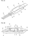
- a cable connection structure 3C according to the third embodiment includes a plurality of round cables W1, a flat cable W2, a holder 10A for holding end portions of the plurality of round cables W1 and the end portion of the flat cable W2, connection portions 20 in which core wires 1a of the round cables W1 and conductors 2a of the flat cable W2, respectively, and a heat-shrinkable tube 24 to which a hot melt adhesive (thermoplastic adhesive) 23 is attached and which is a waterproof outer portion covering the outer periphery of the holder 10A.
- a hot melt adhesive thermoplastic adhesive
- Each of the round cables W1 has a round cross section and includes the core wire 1a and an insulating jacket 1b covering the outer periphery of the core wire 1a.
- the core wire 1a is exposed from the insulating jacket 1b at the end portion of each of the round cables W1.
- the flat cable W2 has a cross section in a flat rectangular shape and includes a plurality of spaced-apart tabular conductors 2a and an insulating jacket 2b which covers the plurality of tabular conductors 2a together. Each of the conductors 2a is exposed from the insulating jacket 2b at the end portion of the flat cable W2.
- the holder 10A is formed of an insulating material. As in the FIGS. 10A and 10B 1, the holder 10A includes a plurality of round cable arrangement grooves 26 provided on one side of a base wall 25 and a flat cable arrangement chamber 27 provided on the other side of the base wall 25.
- each of the round cable arrangement grooves 26 is opened.
- the round cable arrangement grooves 26 are divided by partitions 25a in the transverse direction.
- the distal end side of each of the round cable arrangement grooves 26 in the transverse direction is partitioned by partition walls 25b.
- the horn 33 of the ultrasonic welding apparatus 30 is inserted from the opening portions above the partition walls 25b.
- Each of the round cables W1 is disposed in the corresponding round cable arrangement groove 26 so that the core wire 1a exposed at the end portion is positioned at the portion separated by the partition walls 25b.
- the flat cable assembly chamber 27 is formed so as to be surrounded by the base wall 25 and a surrounding wall 28 covering the lower part of the base wall 25.
- the partition walls 25b extend to the distal end side of the flat cable mounting chamber 27 in the transverse direction.
- the distal end face of the flat cable assembly chamber 27 is divided transversely by the partition walls 25b.
- a plurality of through holes 28a opened to the flat cable assembly chamber 27 are formed at the position on the surrounding wall 28 where the partition walls 25b are positioned.
- the anvil 34 of the ultrasonic welding apparatus 30 is inserted from the through holes 28a.
- the flat cable W2 is arranged in the flat cable assembly chamber 27 so that the conductors 2a exposed at the end portion are positioned at the portions separated by the partition walls 25b.
- a pair of hanging claws 29 are provided, which protrude from the position on the side opposite to the direction in which the flat cable W2 is inserted into the flat cable assembly chamber 27.
- the round cables W1 and the flat cable W2 held by the holder 10A are pulled out of the holder 10A in the same direction.
- the end section of each round cable W1 and the end portion of the flat cable W2 are arranged to overlap each other.
- the hot melt adhesive (insulating resin) 23 which is a thermoplastic adhesive, is applied over the entire area.
- the hot melt adhesive 23 is thermally melted by heating the shrink tube 24 to cover and solidify the outer exposed surface of the holder 10A and the outer circumference of the round cables W1 and the flat cable W2 pulled out from the holder 10A without gap.
- the shrink tube 24 is made in the shrunken state and covers the outer periphery of the solidified hot melt adhesive 23 without a gap.
- the hot melt adhesive (insulating resin) 23 is gap-free on the outer peripheral surface of each of the round cables W1 and the outer peripheral surface of the flat cable W2 at the position of the round cable W1 pulled outward from the hot melt adhesive 23 and the position of the hot melt adhesive as well 23 outwardly pulled flat cable W2 firmly attached, thus ensuring the waterproof property of the connecting portion 20th
- the manufacturing method of the cable connecting structure 3C according to the third embodiment is performed in the order of a cable adjusting step, a connecting step, and a tube shrinking step that is an external forming step.
- the manufacturing method of the cable connecting structure 3C according to the third embodiment will be described in order.
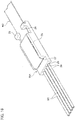
- the end portion of the flat cable W2 as a distal insertion end is inserted into the flat cable assembly chamber 27 of the holder 10A. Then, as in the FIGs. 12A and 12B 1, the end portion of the flat cable W2 is arranged in the flat cable assembly chamber 27 so that the conductors 2a exposed at the end portion of the flat cable W2 are positioned at the positions (positions above the through holes) exposed from the upper openings of the partition walls 25b.
- the round cables W1 are inserted from above into the round cable arrangement grooves 26 above the holder 10A.
- the FIGs. 13A and 13B illustrates the round cables W1 arranged in the round cable arrangement grooves 26 so that the core wires 1a exposed at the end portions of the round cables W1 of the upper openings of the partition walls 25b (positions above the conductors 2a) are positioned exposed.
- the ribbon cable W2 and the round cables W1 need not be inserted in the bracket 10A in any particular order. They can be used at the same time.
- the core wires 1a exposed at the end portions of the round cables W1 and the conductors 2a exposed at the end portion of the flat cable W2 are arranged to overlap each other, and the overlapping portions will be exposed to the outside from the holder 10A.
- the round cables W1 and the flat cable W2 are pulled out of the bracket 10A so as to overlap in the same direction.
- the round cables W1 and the flat cable W2 are electrically connected to the ultrasonic welding device 30 by ultrasonic welding.
- the ultrasonic welding apparatus 30 includes the anvil 34 and the horn 33 at the location facing the anvil 34.
- the horn 33 is provided at the distal end of an arm portion 32 whose base end portion is supported by a device main body 31.
- the flat cable W2 is first inserted into the line arrow indicated by the dashed line arrow FIG. 15 bent direction and then in the state of the guide in a direction other than the withdrawn direction from the holder 10 A, in particular in the diametrically opposite withdrawn direction, as in FIG. 16 shown executed. Subsequently, as in the FIGs. 17A and 17B shown, the holder 10A with the round cables W1 and pulled out of different directions flat cable W2 inserted into the shrink tube 24.
- the shrink tube 24 and the hot-melt adhesive 23 are heated. Then it shrinks, as in FIG. 18 shown, the shrink tube 24, while the hot melt 23 melts (fluidized).
- the molten hot-melt adhesive 23 is gap-free on the outer an exposed surface of the holder 10A, the connecting portions 20 in which the core wires 1a of the round cables W1 and the holders 2a held by the holder 2a of the flat cable W2 are connected to the outer circumference of the holder 10A and the outer circumference of the round cables W1 and pulled out of the holder 10A Flat cable W2 firmly attached and is solidified by cooling in the pasted state.
- the solidified hot melt adhesive 23 collectively covers the outer exposed surface of the holder 10A, the connecting portions 20 in which the core wires 1a of the round cables W1 and the conductors 2a held by the holder 10A of the flat cable W2 are connected, the outer periphery of the holder 10A and the outer periphery of the Round cable W1 and the flat cable W2 pulled out from the holder 10A, and the heat-shrinkable tube 24 covers the outer periphery of the hot-melt adhesive 23 without gap.
- the cable connecting structure 3C according to the third embodiment as shown in FIGS FIGs. 9A and 9B shown.
- the cable connection structure 3C includes the round cables W1 each having a round cross section and having the core wire 1a and the round insulating jacket 1b covering the outer periphery of the core wire 1a, the flat cable W2 having a cross section in a flat rectangular shape Shape and the tabular conductor 2a and the conductor 2a covering flat insulating sheath 2b, wherein the holder 10A holds the end portions of the round cable W1 and the end portion of the flat cable W2 and pulls the round cable W1 and the flat cable W2 in the same direction in an overlapping state , the connecting portions 20 in which the core wires 1a connected from the end portions of the round cables W1 and the conductors 2a exposed from the end portion of the flat cable W2 held by the holder 10A are connected, and the heat-shrinkable tube 24 to which the hot-melt adhesive 23 is attached is, as a waterproof outer section, d it together covers the outer periphery of the holder 10A and the outer circumference
- the round cables W1 and the flat cable W2 are pulled out of the holder 10 in the same direction, whereby they are connected to a connecting device such as the ultrasonic welding device 30 regardless of a length of the Flat cable W2 can be manufactured.
- the holder 10 is divided into the round cable holder 11 and the flat cable holder 15. However, it can be a component.
- the holder 10A is a component.
- the holder 10A may be made of two components as in the cable connection structure 3A according to the first embodiment and the cable connection structure 3B according to the second embodiment.
- the tube-shrinking step is performed so that the flat cable W2 is bent to be guided and adjusted in a direction other than the extended direction from the holder 10A.
- the flat cable W2 may not be bent, and the tube shrinking step (heating with respect to the shrink tube 24 and hot melt adhesive 23) may be performed while the flat cable W2 and the round cables W1 are pulled out of the holder 10A in the same direction.
- the shrink tube 24 which changes shape by thermal action is used.
- it may be a shrink tube that changes its shape by exposure to light or the like.
- the core wires 1a of the round cables W1 and the conductors 2a of the flat cable W2 are ultrasonically welded to the ultrasonic welding apparatus 30.
- a terminal device capable of electrically connecting the core wires 1a of the round cables W1 and the conductors 2a of the flat cable W2 which may be, for example, a resistance welding device.
Landscapes
- Engineering & Computer Science (AREA)
- Manufacturing & Machinery (AREA)
- Coupling Device And Connection With Printed Circuit (AREA)
- Manufacturing Of Electrical Connectors (AREA)
- Insulated Conductors (AREA)
- Connections Effected By Soldering, Adhesion, Or Permanent Deformation (AREA)
- Connector Housings Or Holding Contact Members (AREA)
- Multi-Conductor Connections (AREA)
Applications Claiming Priority (1)
| Application Number | Priority Date | Filing Date | Title |
|---|---|---|---|
| JP2018043944A JP7088696B2 (ja) | 2018-03-12 | 2018-03-12 | 電線接続構造及び電線接続構造の製造方法 |
Publications (1)
| Publication Number | Publication Date |
|---|---|
| EP3540858A1 true EP3540858A1 (fr) | 2019-09-18 |
Family
ID=65766884
Family Applications (1)
| Application Number | Title | Priority Date | Filing Date |
|---|---|---|---|
| EP19162113.5A Withdrawn EP3540858A1 (fr) | 2018-03-12 | 2019-03-12 | Structure de raccordement de câblage et procédé de fabrication de structure de raccordement de câblage |
Country Status (4)
| Country | Link |
|---|---|
| US (1) | US10630020B2 (fr) |
| EP (1) | EP3540858A1 (fr) |
| JP (1) | JP7088696B2 (fr) |
| CN (1) | CN110265796A (fr) |
Cited By (1)
| Publication number | Priority date | Publication date | Assignee | Title |
|---|---|---|---|---|
| EP4120481A1 (fr) * | 2021-07-16 | 2023-01-18 | H & B Electronic GmbH & Co. KG | Ensemble de connexion |
Families Citing this family (4)
| Publication number | Priority date | Publication date | Assignee | Title |
|---|---|---|---|---|
| JP6947138B2 (ja) * | 2018-08-21 | 2021-10-13 | 株式会社オートネットワーク技術研究所 | 多芯ケーブルの止水構造 |
| US11955747B2 (en) * | 2020-01-03 | 2024-04-09 | Aptiv Technologies Limited | Watertight electrical connection system to flat-wire conductors of a flexible printed circuit |
| CN112908534B (zh) * | 2021-01-18 | 2023-01-17 | 苏州洛佳伊电子科技有限公司 | 一种挤压式抗拉扯ffc排线及其制造方法 |
| JP7315597B2 (ja) * | 2021-02-16 | 2023-07-26 | 矢崎総業株式会社 | ジョイント用整列治具、ジョイント前電線束サブアッシー、溶着機、及び電線束ジョイント方法 |
Citations (6)
| Publication number | Priority date | Publication date | Assignee | Title |
|---|---|---|---|---|
| US3852517A (en) * | 1972-06-12 | 1974-12-03 | Raychem Corp | Conductive insert for heat recoverable electrical connector |
| US5021611A (en) * | 1988-10-07 | 1991-06-04 | Yazaki Corporation | Waterproof joint for wireharness |
| EP0810122A2 (fr) * | 1996-05-27 | 1997-12-03 | Yazaki Corporation | Structure de connexion d'un cable plat |
| US5780774A (en) * | 1995-05-30 | 1998-07-14 | Yazaki Corporation | Connection structure of electric wire and flat cable |
| US6232556B1 (en) * | 2000-02-23 | 2001-05-15 | Delphi Technologies, Inc. | Flat wire to round wire connection system |
| US6247977B1 (en) * | 1998-04-27 | 2001-06-19 | Yazaki Corporation | Connector for flat cable |
Family Cites Families (4)
| Publication number | Priority date | Publication date | Assignee | Title |
|---|---|---|---|---|
| JP3170173B2 (ja) * | 1995-04-25 | 2001-05-28 | 矢崎総業株式会社 | 電線とフラットケーブルの接続コネクタ及びその製造方法 |
| JP2000348791A (ja) | 1999-06-01 | 2000-12-15 | Sumitomo Wiring Syst Ltd | フラットケーブルと電線の接続構造 |
| TWM421617U (en) * | 2011-06-09 | 2012-01-21 | Bing Xu Prec Co Ltd | Cable connector |
| JP2014073637A (ja) * | 2012-10-04 | 2014-04-24 | Sumitomo Electric Fine Polymer Inc | 熱収縮チューブ |
-
2018
- 2018-03-12 JP JP2018043944A patent/JP7088696B2/ja active Active
-
2019
- 2019-03-08 US US16/296,884 patent/US10630020B2/en active Active
- 2019-03-12 EP EP19162113.5A patent/EP3540858A1/fr not_active Withdrawn
- 2019-03-12 CN CN201910186341.5A patent/CN110265796A/zh not_active Withdrawn
Patent Citations (6)
| Publication number | Priority date | Publication date | Assignee | Title |
|---|---|---|---|---|
| US3852517A (en) * | 1972-06-12 | 1974-12-03 | Raychem Corp | Conductive insert for heat recoverable electrical connector |
| US5021611A (en) * | 1988-10-07 | 1991-06-04 | Yazaki Corporation | Waterproof joint for wireharness |
| US5780774A (en) * | 1995-05-30 | 1998-07-14 | Yazaki Corporation | Connection structure of electric wire and flat cable |
| EP0810122A2 (fr) * | 1996-05-27 | 1997-12-03 | Yazaki Corporation | Structure de connexion d'un cable plat |
| US6247977B1 (en) * | 1998-04-27 | 2001-06-19 | Yazaki Corporation | Connector for flat cable |
| US6232556B1 (en) * | 2000-02-23 | 2001-05-15 | Delphi Technologies, Inc. | Flat wire to round wire connection system |
Cited By (2)
| Publication number | Priority date | Publication date | Assignee | Title |
|---|---|---|---|---|
| EP4120481A1 (fr) * | 2021-07-16 | 2023-01-18 | H & B Electronic GmbH & Co. KG | Ensemble de connexion |
| US12327958B2 (en) | 2021-07-16 | 2025-06-10 | H & B Electronic Gmbh & Co. Kg | Connection assembly |
Also Published As
| Publication number | Publication date |
|---|---|
| CN110265796A (zh) | 2019-09-20 |
| JP2019160506A (ja) | 2019-09-19 |
| JP7088696B2 (ja) | 2022-06-21 |
| US10630020B2 (en) | 2020-04-21 |
| US20190280423A1 (en) | 2019-09-12 |
Similar Documents
| Publication | Publication Date | Title |
|---|---|---|
| EP2027629B1 (fr) | Connecteur enfichable blindé et son procédé de réalisation | |
| DE69210307T2 (de) | Kabelverbindungen und Endstücke | |
| DE112016003124B4 (de) | Abschirmstruktur und abschirmendes geflochtenes Element | |
| DE2329908C2 (fr) | ||
| DE10218400B4 (de) | Abschirmanordnung an einem Abschirmflachkabel und Verfahren zu deren Herstellung | |
| DE10218398A1 (de) | Verfahren zur Herstellung einer Abzweigverbindung an einem abgeschirmten Leiter | |
| EP3641072A1 (fr) | Connecteur electrique blinde | |
| DE102007030057A1 (de) | Spulenkomponente | |
| DE102015214510B4 (de) | Kabelbaum | |
| DE19909322B4 (de) | Verbindungsstruktur für ummantelte Leitungen und Verfahren zur Herstellung einer Verbindungsstruktur für ummantelte Leitungen | |
| DE69113463T2 (de) | Kabelbaum und kabelabzweig. | |
| DE10349240B4 (de) | Abdichtanordnung zur Anbringung an einem ummantelten Kabel | |
| DE3789600T2 (de) | Kabelverbindungen mit Abdichtung. | |
| DE19839302A1 (de) | Geschirmter Kabelverbindungsaufbau und Herstellverfahren | |
| DE102017221958B4 (de) | Kappe für einen äußeren Endabschnitt und Kabelbaum | |
| DE19839220B4 (de) | Verbindungsverfahren für einen abgeschirmten Draht | |
| DE19901012C2 (de) | Endstückaufbau für ein geschirmtes Kabel und Verfahren zur Herstellung derselben | |
| EP0537487B1 (fr) | Dispositif pour rendre étanche la partie terminale d'une manchette thermorétractable | |
| DE69300485T2 (de) | Kabelverbinder. | |
| DE10218399B4 (de) | Anordnung mit einem mehradrigen Abschirmkabel | |
| DE19909335A1 (de) | Verbindungsstruktur für ummantelte Leitungen | |
| DE10216026A1 (de) | Anschlußkasten und Kabelbaum-Verbindungsverfahren | |
| DE60209748T2 (de) | Mehrteilige isolierumhüllung | |
| DE202016102993U1 (de) | Fixier- und Abdichtungsanordnung | |
| DE3636927A1 (de) | Verbindungskonstruktion fuer leitungsdraehte und verfahren zu ihrer herstellung |
Legal Events
| Date | Code | Title | Description |
|---|---|---|---|
| PUAI | Public reference made under article 153(3) epc to a published international application that has entered the european phase |
Free format text: ORIGINAL CODE: 0009012 |
|
| 17P | Request for examination filed |
Effective date: 20190312 |
|
| AK | Designated contracting states |
Kind code of ref document: A1 Designated state(s): AL AT BE BG CH CY CZ DE DK EE ES FI FR GB GR HR HU IE IS IT LI LT LU LV MC MK MT NL NO PL PT RO RS SE SI SK SM TR |
|
| AX | Request for extension of the european patent |
Extension state: BA ME |
|
| RBV | Designated contracting states (corrected) |
Designated state(s): AL AT BE BG CH CY CZ DE DK EE ES FI FR GB GR HR HU IE IS IT LI LT LU LV MC MK MT NL NO PL PT RO RS SE SI SK SM TR |
|
| STAA | Information on the status of an ep patent application or granted ep patent |
Free format text: STATUS: THE APPLICATION HAS BEEN WITHDRAWN |
|
| 18W | Application withdrawn |
Effective date: 20200714 |