EP3540865A1 - Agencement de conducteur extérieur - Google Patents
Agencement de conducteur extérieur Download PDFInfo
- Publication number
- EP3540865A1 EP3540865A1 EP19160510.4A EP19160510A EP3540865A1 EP 3540865 A1 EP3540865 A1 EP 3540865A1 EP 19160510 A EP19160510 A EP 19160510A EP 3540865 A1 EP3540865 A1 EP 3540865A1
- Authority
- EP
- European Patent Office
- Prior art keywords
- outer conductor
- main body
- contact
- ring
- arrangement according
- Prior art date
- Legal status (The legal status is an assumption and is not a legal conclusion. Google has not performed a legal analysis and makes no representation as to the accuracy of the status listed.)
- Granted
Links
Images
Classifications
-
- H—ELECTRICITY
- H01—ELECTRIC ELEMENTS
- H01R—ELECTRICALLY-CONDUCTIVE CONNECTIONS; STRUCTURAL ASSOCIATIONS OF A PLURALITY OF MUTUALLY-INSULATED ELECTRICAL CONNECTING ELEMENTS; COUPLING DEVICES; CURRENT COLLECTORS
- H01R13/00—Details of coupling devices of the kinds covered by groups H01R12/70 or H01R24/00 - H01R33/00
- H01R13/02—Contact members
-
- H—ELECTRICITY
- H01—ELECTRIC ELEMENTS
- H01R—ELECTRICALLY-CONDUCTIVE CONNECTIONS; STRUCTURAL ASSOCIATIONS OF A PLURALITY OF MUTUALLY-INSULATED ELECTRICAL CONNECTING ELEMENTS; COUPLING DEVICES; CURRENT COLLECTORS
- H01R13/00—Details of coupling devices of the kinds covered by groups H01R12/70 or H01R24/00 - H01R33/00
- H01R13/648—Protective earth or shield arrangements on coupling devices, e.g. anti-static shielding
- H01R13/658—High frequency shielding arrangements, e.g. against EMI [Electro-Magnetic Interference] or EMP [Electro-Magnetic Pulse]
- H01R13/6581—Shield structure
- H01R13/6582—Shield structure with resilient means for engaging mating connector
-
- H—ELECTRICITY
- H01—ELECTRIC ELEMENTS
- H01R—ELECTRICALLY-CONDUCTIVE CONNECTIONS; STRUCTURAL ASSOCIATIONS OF A PLURALITY OF MUTUALLY-INSULATED ELECTRICAL CONNECTING ELEMENTS; COUPLING DEVICES; CURRENT COLLECTORS
- H01R13/00—Details of coupling devices of the kinds covered by groups H01R12/70 or H01R24/00 - H01R33/00
- H01R13/02—Contact members
- H01R13/15—Pins, blades or sockets having separate spring member for producing or increasing contact pressure
- H01R13/18—Pins, blades or sockets having separate spring member for producing or increasing contact pressure with the spring member surrounding the socket
-
- H—ELECTRICITY
- H01—ELECTRIC ELEMENTS
- H01R—ELECTRICALLY-CONDUCTIVE CONNECTIONS; STRUCTURAL ASSOCIATIONS OF A PLURALITY OF MUTUALLY-INSULATED ELECTRICAL CONNECTING ELEMENTS; COUPLING DEVICES; CURRENT COLLECTORS
- H01R13/00—Details of coupling devices of the kinds covered by groups H01R12/70 or H01R24/00 - H01R33/00
- H01R13/40—Securing contact members in or to a base or case; Insulating of contact members
Definitions
- the present invention relates to an outer conductor arrangement and a manufacturing method for an outer conductor arrangement.
- Plug-in connectors are known, for example, from Positronic's "PosiBand” plug with both open entry and closed entry.
- FIG. 3 A connector with an open inlet is in FIG. 3 shown.
- Such connectors have an interface-side leading edge, which is not circumferentially closed on. In general, interruptions of the leading edge are formed by contact tabs.
- Open-entry connectors can better compensate for manufacturing tolerances and reduce the insertion forces required for insertion.
- a connector with a closed inlet is in FIG. 4 shown.
- Such connectors have a closed interface-side leading edge.
- Contact straps can be surrounded by a housing. Closed-entry connectors prevent the connector from being damaged by mechanical forces, such as a mating attempt with a wrong mating connector. They also lead to significantly increased insertion forces.
- FIG. 5 is an outer conductor 90 of a high-voltage (HV) connector, which is designed for frequencies in the megahertz range shown.
- the outer conductor comprises a closed inlet 91 and resilient contact tabs 92 with contact points 93 located behind the closed inlet. Frequency-dependent resonances occur at the outer conductor due to capacitances between the connector. Although the aforementioned drawbacks in this frequency range do not yet occur, there is a need to provide an outer conductor which is suitable for a plug in a higher frequency range.
- the US 20140364013 A1 and the DE 202013001452 U1 show an outer conductor arrangement for a plug connector comprising an outer conductor main body and an outer conductor ring, wherein the outer conductor main body has a plurality of contact tabs, wherein the outer conductor ring adjoins an interface-side end of the outer conductor main body, is connected to at least one connection region by means of a retaining tab to the outer conductor main body and is of a closed structure, to form a closed entry of the outer conductor arrangement, wherein contact tabs are provided, which are not connected to the outer conductor ring.
- the present invention has the object, a connector with a closed Entry and improved impedance properties.
- the idea underlying the present invention is to arrange ends of contact lugs of an outer conductor behind an outer conductor ring so that the contact lugs are flexibly deformable, in order to ensure low insertion forces, and at the same time to create a closed entry through an outer conductor ring.
- the contact tabs not connected to the outer conductor ring have the same tolerance-compensating properties as the contact tabs according to FIG. 7.
- a ring is understood to mean a peripheral object. Its cross-sectional area may be, among other things, round, oval, elliptical or the like.
- the outer conductor arrangement has a diameter jump inwardly between the outer conductor main body and the outer conductor ring. Diameter jumps in the outer conductor allow the impedance to be adjusted.
- the outer conductor ring has no bulge or indentation.
- the outer conductor ring is adapted to protect contact straps from mechanical forces. This is necessary if a connector is to be plugged from an oblique direction or to withstand force effects from an oblique direction without damaging the outer conductor when plugged. According to one embodiment of the present invention, this protection of the contact tabs can be ensured by a closed entry of the outer conductor.
- This embodiment of the present invention thus solves the problem of reducing insertion forces while increasing the stability of a connector.
- the optimization of these two properties is inverse, i. a desired increase in stability leads to an undesirable increase in the insertion forces and vice versa.
- At least one contact tab is formed as a retaining tab, with which the outer conductor ring is connected.
- the outer conductor ring can be attached to the outer conductor main body in a particularly simple and secure manner.
- the outer conductor ring may be attached to another part of the outer conductor.
- the retaining tab does not necessarily have to be a contact tab.
- a contact tab is used to make contact with a mating connector, with which a connector having the outer conductor arrangement is to be connected.
- contact tabs are merely connected to the outer conductor main body, they have resilient properties.
- the retaining tabs may be such that their rigidity is greater than the stiffness of the unattached contact tabs.
- the outer conductor ring is connected to a plurality of tabs, in particular to two tabs on the outer conductor main body, this has a lower resilience than the contact tabs that are not connected to the outer conductor ring.
- a main extension direction of the retaining tab runs in the circumferential direction of the outer conductor retaining ring and / or if the main extension direction of the retaining tab perpendicular to the main extension direction of the contact tabs.
- a connector according to the invention is produced by a stamping method, diameter jumps of the retaining tabs can be produced.
- the outer conductor ring is connected to the outer conductor main body by means of a joining method, e.g. by welding, connected.
- a joining method e.g. by welding
- the outer conductor ring and the outer conductor main body may be made of a continuous part.
- the outer conductor main body has two retaining tabs.
- the retaining tabs can be straight or curved.
- the outer conductor ring has a protective collar, which protrudes in the radial direction in relation to free ends of the contact tabs, wherein the protective collar is set up to protect the contact tabs of the outer conductor main body against mechanical force effects. It can be provided that the protective collar prevents the contact tabs are damaged by entering objects, such as tools.
- the protective collar may, in one embodiment, be a vertical wall projecting from the outer conductor ring, be formed or as a curved tab, which covers the front ends of the contact tabs.
- the contact tabs each have an elevated contact point for contacting a mating connector.
- the contact tabs in the inserted state undergo a bias, whereby the contact improves.
- the shielding of the connector is improved.
- the outer conductor ring and the outer conductor main body are integrally formed.
- the outer conductor main body is formed as a stamped part.
- Stamped parts can be produced in a particularly cost-effective manner.
- the production of stamped parts can be made highly automated.
- creating diameter jumps in punching processes for plug-in connectors is possible only in conjunction with other mechanical disadvantages such as high insertion forces or low contact forces.
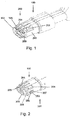
- FIG. 1 shows a schematic view of an outer conductor arrangement 100 according to the invention in the unassembled state.
- the outer conductor assembly 100 of the present invention includes the outer conductor body 200 and the outer conductor ring 300.
- the outer conductor assembly 100 is configured to receive one or more inner conductors and one or more insulating members to provide a coaxial, twinaxial or triaxial connector.
- the outer conductor main body 200 comprises on its upper side and lower side a plurality of contact tabs 201 and on the right and left side in each case a retaining tab, which is designed as a contact tab 203.
- the contact tab 203 is slightly larger than the contact tabs 201 and thus also stiffer than the contact tabs 201.
- the outer tabs 300 are additionally integrally formed on the contact tabs 203, which additionally contribute to an increased rigidity of the contact tabs 203 relative to the contact tabs 201.
- the contact tabs 201 each have a contact point 204 in a front end region.
- the contact point is formed as an increase on the contact tabs 201 and contacted in the inserted state, the outer conductor of a mating connector, which is plugged with outer conductor assembly 100. This ensures electromagnetic shielding at the top and bottom of the outer conductor assembly 100 of FIG the outer conductor main body 200 guided inner conductors (not shown) through the outer conductor main body 200th
- FIG. 2 also have the contact tabs 203 each have a contact point 205.
- the contact point 205 is formed on a spring tab 207 in the contact tab 203. In this way, it is ensured that the outer conductor arrangement 100 also provides an electromagnetic shielding on the sides of the outer conductor arrangement.
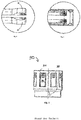
- outer conductor main body 200 provides a diameter jump between the contact tabs 201, 203 and the outer conductor ring 300.
- the outer conductor ring 300 is connected to the outer conductor main body 200 via a weld seam 209.
- the outer conductor main body 200 and the outer conductor ring 300 may be integrally formed.
- the outer conductor ring 300 includes the protective collar 305, which protects the ends of the contact plates 201 from the action of foreign bodies.
Landscapes
- Details Of Connecting Devices For Male And Female Coupling (AREA)
- Coupling Device And Connection With Printed Circuit (AREA)
Priority Applications (1)
| Application Number | Priority Date | Filing Date | Title |
|---|---|---|---|
| EP21182088.1A EP3907830B1 (fr) | 2018-03-15 | 2019-03-04 | Disposition de conducteur externe |
Applications Claiming Priority (2)
| Application Number | Priority Date | Filing Date | Title |
|---|---|---|---|
| DE102018106004 | 2018-03-15 | ||
| DE102019104754.4A DE102019104754A1 (de) | 2018-03-15 | 2019-02-25 | Außenleiteranordnung |
Related Child Applications (1)
| Application Number | Title | Priority Date | Filing Date |
|---|---|---|---|
| EP21182088.1A Division EP3907830B1 (fr) | 2018-03-15 | 2019-03-04 | Disposition de conducteur externe |
Publications (2)
| Publication Number | Publication Date |
|---|---|
| EP3540865A1 true EP3540865A1 (fr) | 2019-09-18 |
| EP3540865B1 EP3540865B1 (fr) | 2021-07-14 |
Family
ID=65685241
Family Applications (2)
| Application Number | Title | Priority Date | Filing Date |
|---|---|---|---|
| EP19160510.4A Active EP3540865B1 (fr) | 2018-03-15 | 2019-03-04 | Agencement de conducteur extérieur |
| EP21182088.1A Active EP3907830B1 (fr) | 2018-03-15 | 2019-03-04 | Disposition de conducteur externe |
Family Applications After (1)
| Application Number | Title | Priority Date | Filing Date |
|---|---|---|---|
| EP21182088.1A Active EP3907830B1 (fr) | 2018-03-15 | 2019-03-04 | Disposition de conducteur externe |
Country Status (2)
| Country | Link |
|---|---|
| EP (2) | EP3540865B1 (fr) |
| CN (1) | CN114649704B (fr) |
Cited By (4)
| Publication number | Priority date | Publication date | Assignee | Title |
|---|---|---|---|---|
| CN115133351A (zh) * | 2022-06-22 | 2022-09-30 | 中航光电科技股份有限公司 | 一种射频同轴连接器及其屏蔽套筒 |
| WO2023017462A1 (fr) * | 2021-08-11 | 2023-02-16 | Te Connectivity Germany Gmbh | Contact d'un connecteur |
| FR3131111A1 (fr) * | 2021-12-22 | 2023-06-23 | Aptiv Technologies Limited | Ensemble de connexion blindé, connecteur pour cet ensemble de connexion et procédé de fabrication d’un élément de blindage pour cet ensemble de connexion |
| US12580343B2 (en) | 2021-09-01 | 2026-03-17 | Fci Usa Llc | High speed, ruggedized connector |
Families Citing this family (1)
| Publication number | Priority date | Publication date | Assignee | Title |
|---|---|---|---|---|
| CN219350728U (zh) * | 2022-12-26 | 2023-07-14 | 长春捷翼汽车科技股份有限公司 | 一种外导体结构 |
Citations (6)
| Publication number | Priority date | Publication date | Assignee | Title |
|---|---|---|---|---|
| EP0476848A1 (fr) * | 1990-09-07 | 1992-03-25 | ITT INDUSTRIES, INC. (a Delaware corporation) | Montage de contact à fiches avec embouchure étranglée |
| DE4312641C2 (de) | 1993-04-19 | 1995-10-12 | Grote & Hartmann | Elektrische Kontakthülse |
| EP0967684A2 (fr) * | 1998-06-25 | 1999-12-29 | Tri-Star Electronics International Inc. | Contact à douille |
| DE102016109266A1 (de) | 2016-05-06 | 2017-11-09 | Rosenberger Hochfrequenztechnik Gmbh & Co. Kg | Steckverbindungsvorrichtung mit wenigstens einem Steckverbinder |
| WO2018099904A1 (fr) | 2016-11-30 | 2018-06-07 | Amphenol-Tuchel Electronics Gmbh | Fiche femelle de connecteur enfichable cylindrique à contacts pour courants forts |
| EP3396791A1 (fr) * | 2017-04-24 | 2018-10-31 | Rosenberger Hochfrequenztechnik GmbH & Co. KG | Agencement de conducteurs de phase |
Family Cites Families (6)
| Publication number | Priority date | Publication date | Assignee | Title |
|---|---|---|---|---|
| EP0844699A3 (fr) * | 1996-11-26 | 1999-07-28 | Siemens Aktiengesellschaft | Elément de connecteur coaxial |
| DE102006006845B3 (de) * | 2006-02-15 | 2007-07-19 | Tyco Electronics Amp Gmbh | Elektrische Außenleiterhülse für einen koaxialen Steckverbinder |
| DE202013001452U1 (de) | 2013-02-14 | 2013-03-21 | Rosenberger Hochfrequenztechnik Gmbh & Co. Kg | Adapter |
| CN104241940A (zh) | 2013-06-08 | 2014-12-24 | 凡甲电子(苏州)有限公司 | 电连接器组合 |
| CN103490200B (zh) * | 2013-09-27 | 2015-07-29 | 苏州华旃航天电器有限公司 | 一种具有冲压接触元件的射频同轴电连接器 |
| CN204424526U (zh) * | 2015-02-13 | 2015-06-24 | 常州市新盛电器有限公司 | 公头单元射频连接器 |
-
2019
- 2019-03-04 EP EP19160510.4A patent/EP3540865B1/fr active Active
- 2019-03-04 EP EP21182088.1A patent/EP3907830B1/fr active Active
- 2019-03-12 CN CN202210379986.2A patent/CN114649704B/zh active Active
Patent Citations (6)
| Publication number | Priority date | Publication date | Assignee | Title |
|---|---|---|---|---|
| EP0476848A1 (fr) * | 1990-09-07 | 1992-03-25 | ITT INDUSTRIES, INC. (a Delaware corporation) | Montage de contact à fiches avec embouchure étranglée |
| DE4312641C2 (de) | 1993-04-19 | 1995-10-12 | Grote & Hartmann | Elektrische Kontakthülse |
| EP0967684A2 (fr) * | 1998-06-25 | 1999-12-29 | Tri-Star Electronics International Inc. | Contact à douille |
| DE102016109266A1 (de) | 2016-05-06 | 2017-11-09 | Rosenberger Hochfrequenztechnik Gmbh & Co. Kg | Steckverbindungsvorrichtung mit wenigstens einem Steckverbinder |
| WO2018099904A1 (fr) | 2016-11-30 | 2018-06-07 | Amphenol-Tuchel Electronics Gmbh | Fiche femelle de connecteur enfichable cylindrique à contacts pour courants forts |
| EP3396791A1 (fr) * | 2017-04-24 | 2018-10-31 | Rosenberger Hochfrequenztechnik GmbH & Co. KG | Agencement de conducteurs de phase |
Non-Patent Citations (1)
| Title |
|---|
| ANONYMUS: "System for Data Transmission up to 20 Gbps H-MTD High-Speed Modular Twisted-Pair Data", ROSENBERGER HOCHFREQUENZTECHNIK GMBH & CO. KG, 2017, pages 6pp, XP055760208 |
Cited By (7)
| Publication number | Priority date | Publication date | Assignee | Title |
|---|---|---|---|---|
| WO2023017462A1 (fr) * | 2021-08-11 | 2023-02-16 | Te Connectivity Germany Gmbh | Contact d'un connecteur |
| US20230046887A1 (en) * | 2021-08-11 | 2023-02-16 | TE Connectivity Services Gmbh | Contact Of A Connector |
| US12170424B2 (en) * | 2021-08-11 | 2024-12-17 | Te Connectivity Germany Gmbh | Contact of an electrical connector with protection tabs for cantilever beams |
| US12580343B2 (en) | 2021-09-01 | 2026-03-17 | Fci Usa Llc | High speed, ruggedized connector |
| FR3131111A1 (fr) * | 2021-12-22 | 2023-06-23 | Aptiv Technologies Limited | Ensemble de connexion blindé, connecteur pour cet ensemble de connexion et procédé de fabrication d’un élément de blindage pour cet ensemble de connexion |
| EP4254680A1 (fr) * | 2021-12-22 | 2023-10-04 | Aptiv Technologies Limited | Ensemble de connexion blindé, connecteur pour cet ensemble de connexion et procédé de fabrication d'un élément de blindage pour cet ensemble de connexion |
| CN115133351A (zh) * | 2022-06-22 | 2022-09-30 | 中航光电科技股份有限公司 | 一种射频同轴连接器及其屏蔽套筒 |
Also Published As
| Publication number | Publication date |
|---|---|
| EP3907830C0 (fr) | 2024-02-21 |
| EP3540865B1 (fr) | 2021-07-14 |
| CN114649704B (zh) | 2024-04-30 |
| EP3907830A1 (fr) | 2021-11-10 |
| CN114649704A (zh) | 2022-06-21 |
| EP3907830B1 (fr) | 2024-02-21 |
Similar Documents
| Publication | Publication Date | Title |
|---|---|---|
| EP3540865B1 (fr) | Agencement de conducteur extérieur | |
| EP3396791B1 (fr) | Agencement de conducteurs de phase | |
| DE102019104754A1 (de) | Außenleiteranordnung | |
| EP2950395B1 (fr) | Couronne ressort pour un blindage de connecteurs électriques | |
| DE102010017265B4 (de) | Kabelanschlusseinrichtung und Verfahren zum Anschließen eines Kabels an eine Kabelanschlusseinrichtung | |
| EP3227971B1 (fr) | Connexion enfichable hf avec douille de contact à fermeture automatique | |
| DE102012105258A1 (de) | Schirmhülse und Abschirmendelement umfassend eine Schirmhülse | |
| DE202012008970U1 (de) | Steckverbinder | |
| DE202008014168U1 (de) | Steckverbindung mit einem Stecker- und einem Buchsenteil und diese aufnehmenden Adaptergehäusen | |
| EP3823110A1 (fr) | Support de contact pour connecteurs enfichables électriques et connecteur enfichable correspondant | |
| DE102016006598A1 (de) | Steckverbinder | |
| DE112018005968T5 (de) | Verbinderanschluss und Verbinder | |
| DE102012007481A1 (de) | Steckverbinder mit Kontaktverrastungsmittel | |
| DE2528186A1 (de) | Masseschlussfeder fuer elektrischen verbinder | |
| DE102021112143B4 (de) | Elektrisches Kontaktelement mit einem Stützring | |
| DE102018118405B3 (de) | Steckverbinder sowie Steckverbindung mit einem solchen Steckverbinder | |
| EP2945226B1 (fr) | Connecteur et procédé | |
| EP1632042B1 (fr) | Dispositif pour absorber un bruissement | |
| EP4158233B1 (fr) | Fiche de connexion et ensemble fiche formé à partir de celle-ci | |
| DE102022122506A1 (de) | Universell einsetzbares Gehäuse zur Abdeckung von Kontaktelementen | |
| EP2463959B1 (fr) | Connecteur | |
| WO2019161848A1 (fr) | Connecteur comprenant un élément de polarisation ainsi qu'un système et un procédé pour le montage, le branchement et le débranchement de ce connecteur | |
| EP2337161B1 (fr) | Agencement de prise et dispositif d'étanchéification pour au moins une ligne, notamment une ligne électrique | |
| EP3364507A1 (fr) | Connecteur électrique pour un câble électrique multi-fils | |
| DE102016213291A1 (de) | Steckereinsatz mit Positionierelement |
Legal Events
| Date | Code | Title | Description |
|---|---|---|---|
| PUAI | Public reference made under article 153(3) epc to a published international application that has entered the european phase |
Free format text: ORIGINAL CODE: 0009012 |
|
| STAA | Information on the status of an ep patent application or granted ep patent |
Free format text: STATUS: REQUEST FOR EXAMINATION WAS MADE |
|
| 17P | Request for examination filed |
Effective date: 20190304 |
|
| AK | Designated contracting states |
Kind code of ref document: A1 Designated state(s): AL AT BE BG CH CY CZ DE DK EE ES FI FR GB GR HR HU IE IS IT LI LT LU LV MC MK MT NL NO PL PT RO RS SE SI SK SM TR |
|
| AX | Request for extension of the european patent |
Extension state: BA ME |
|
| STAA | Information on the status of an ep patent application or granted ep patent |
Free format text: STATUS: EXAMINATION IS IN PROGRESS |
|
| 17Q | First examination report despatched |
Effective date: 20191008 |
|
| TPAC | Observations filed by third parties |
Free format text: ORIGINAL CODE: EPIDOSNTIPA |
|
| GRAP | Despatch of communication of intention to grant a patent |
Free format text: ORIGINAL CODE: EPIDOSNIGR1 |
|
| STAA | Information on the status of an ep patent application or granted ep patent |
Free format text: STATUS: GRANT OF PATENT IS INTENDED |
|
| INTG | Intention to grant announced |
Effective date: 20210211 |
|
| GRAS | Grant fee paid |
Free format text: ORIGINAL CODE: EPIDOSNIGR3 |
|
| GRAA | (expected) grant |
Free format text: ORIGINAL CODE: 0009210 |
|
| STAA | Information on the status of an ep patent application or granted ep patent |
Free format text: STATUS: THE PATENT HAS BEEN GRANTED |
|
| AK | Designated contracting states |
Kind code of ref document: B1 Designated state(s): AL AT BE BG CH CY CZ DE DK EE ES FI FR GB GR HR HU IE IS IT LI LT LU LV MC MK MT NL NO PL PT RO RS SE SI SK SM TR |
|
| REG | Reference to a national code |
Ref country code: GB Ref legal event code: FG4D Free format text: NOT ENGLISH |
|
| REG | Reference to a national code |
Ref country code: IE Ref legal event code: FG4D Free format text: LANGUAGE OF EP DOCUMENT: GERMAN |
|
| REG | Reference to a national code |
Ref country code: DE Ref legal event code: R096 Ref document number: 502019001799 Country of ref document: DE |
|
| REG | Reference to a national code |
Ref country code: AT Ref legal event code: REF Ref document number: 1411378 Country of ref document: AT Kind code of ref document: T Effective date: 20210815 |
|
| REG | Reference to a national code |
Ref country code: SE Ref legal event code: TRGR |
|
| REG | Reference to a national code |
Ref country code: LT Ref legal event code: MG9D |
|
| REG | Reference to a national code |
Ref country code: NL Ref legal event code: MP Effective date: 20210714 |
|
| PG25 | Lapsed in a contracting state [announced via postgrant information from national office to epo] |
Ref country code: ES Free format text: LAPSE BECAUSE OF FAILURE TO SUBMIT A TRANSLATION OF THE DESCRIPTION OR TO PAY THE FEE WITHIN THE PRESCRIBED TIME-LIMIT Effective date: 20210714 Ref country code: FI Free format text: LAPSE BECAUSE OF FAILURE TO SUBMIT A TRANSLATION OF THE DESCRIPTION OR TO PAY THE FEE WITHIN THE PRESCRIBED TIME-LIMIT Effective date: 20210714 Ref country code: RS Free format text: LAPSE BECAUSE OF FAILURE TO SUBMIT A TRANSLATION OF THE DESCRIPTION OR TO PAY THE FEE WITHIN THE PRESCRIBED TIME-LIMIT Effective date: 20210714 Ref country code: HR Free format text: LAPSE BECAUSE OF FAILURE TO SUBMIT A TRANSLATION OF THE DESCRIPTION OR TO PAY THE FEE WITHIN THE PRESCRIBED TIME-LIMIT Effective date: 20210714 Ref country code: NL Free format text: LAPSE BECAUSE OF FAILURE TO SUBMIT A TRANSLATION OF THE DESCRIPTION OR TO PAY THE FEE WITHIN THE PRESCRIBED TIME-LIMIT Effective date: 20210714 Ref country code: NO Free format text: LAPSE BECAUSE OF FAILURE TO SUBMIT A TRANSLATION OF THE DESCRIPTION OR TO PAY THE FEE WITHIN THE PRESCRIBED TIME-LIMIT Effective date: 20211014 Ref country code: PT Free format text: LAPSE BECAUSE OF FAILURE TO SUBMIT A TRANSLATION OF THE DESCRIPTION OR TO PAY THE FEE WITHIN THE PRESCRIBED TIME-LIMIT Effective date: 20211115 Ref country code: BG Free format text: LAPSE BECAUSE OF FAILURE TO SUBMIT A TRANSLATION OF THE DESCRIPTION OR TO PAY THE FEE WITHIN THE PRESCRIBED TIME-LIMIT Effective date: 20211014 Ref country code: LT Free format text: LAPSE BECAUSE OF FAILURE TO SUBMIT A TRANSLATION OF THE DESCRIPTION OR TO PAY THE FEE WITHIN THE PRESCRIBED TIME-LIMIT Effective date: 20210714 |
|
| PG25 | Lapsed in a contracting state [announced via postgrant information from national office to epo] |
Ref country code: PL Free format text: LAPSE BECAUSE OF FAILURE TO SUBMIT A TRANSLATION OF THE DESCRIPTION OR TO PAY THE FEE WITHIN THE PRESCRIBED TIME-LIMIT Effective date: 20210714 Ref country code: LV Free format text: LAPSE BECAUSE OF FAILURE TO SUBMIT A TRANSLATION OF THE DESCRIPTION OR TO PAY THE FEE WITHIN THE PRESCRIBED TIME-LIMIT Effective date: 20210714 Ref country code: GR Free format text: LAPSE BECAUSE OF FAILURE TO SUBMIT A TRANSLATION OF THE DESCRIPTION OR TO PAY THE FEE WITHIN THE PRESCRIBED TIME-LIMIT Effective date: 20211015 |
|
| REG | Reference to a national code |
Ref country code: DE Ref legal event code: R097 Ref document number: 502019001799 Country of ref document: DE |
|
| PG25 | Lapsed in a contracting state [announced via postgrant information from national office to epo] |
Ref country code: DK Free format text: LAPSE BECAUSE OF FAILURE TO SUBMIT A TRANSLATION OF THE DESCRIPTION OR TO PAY THE FEE WITHIN THE PRESCRIBED TIME-LIMIT Effective date: 20210714 |
|
| PLBE | No opposition filed within time limit |
Free format text: ORIGINAL CODE: 0009261 |
|
| STAA | Information on the status of an ep patent application or granted ep patent |
Free format text: STATUS: NO OPPOSITION FILED WITHIN TIME LIMIT |
|
| PG25 | Lapsed in a contracting state [announced via postgrant information from national office to epo] |
Ref country code: SM Free format text: LAPSE BECAUSE OF FAILURE TO SUBMIT A TRANSLATION OF THE DESCRIPTION OR TO PAY THE FEE WITHIN THE PRESCRIBED TIME-LIMIT Effective date: 20210714 Ref country code: SK Free format text: LAPSE BECAUSE OF FAILURE TO SUBMIT A TRANSLATION OF THE DESCRIPTION OR TO PAY THE FEE WITHIN THE PRESCRIBED TIME-LIMIT Effective date: 20210714 Ref country code: RO Free format text: LAPSE BECAUSE OF FAILURE TO SUBMIT A TRANSLATION OF THE DESCRIPTION OR TO PAY THE FEE WITHIN THE PRESCRIBED TIME-LIMIT Effective date: 20210714 Ref country code: EE Free format text: LAPSE BECAUSE OF FAILURE TO SUBMIT A TRANSLATION OF THE DESCRIPTION OR TO PAY THE FEE WITHIN THE PRESCRIBED TIME-LIMIT Effective date: 20210714 Ref country code: CZ Free format text: LAPSE BECAUSE OF FAILURE TO SUBMIT A TRANSLATION OF THE DESCRIPTION OR TO PAY THE FEE WITHIN THE PRESCRIBED TIME-LIMIT Effective date: 20210714 Ref country code: AL Free format text: LAPSE BECAUSE OF FAILURE TO SUBMIT A TRANSLATION OF THE DESCRIPTION OR TO PAY THE FEE WITHIN THE PRESCRIBED TIME-LIMIT Effective date: 20210714 |
|
| 26N | No opposition filed |
Effective date: 20220419 |
|
| PG25 | Lapsed in a contracting state [announced via postgrant information from national office to epo] |
Ref country code: MC Free format text: LAPSE BECAUSE OF FAILURE TO SUBMIT A TRANSLATION OF THE DESCRIPTION OR TO PAY THE FEE WITHIN THE PRESCRIBED TIME-LIMIT Effective date: 20210714 |
|
| REG | Reference to a national code |
Ref country code: CH Ref legal event code: PL |
|
| REG | Reference to a national code |
Ref country code: BE Ref legal event code: MM Effective date: 20220331 |
|
| PG25 | Lapsed in a contracting state [announced via postgrant information from national office to epo] |
Ref country code: LU Free format text: LAPSE BECAUSE OF NON-PAYMENT OF DUE FEES Effective date: 20220304 Ref country code: LI Free format text: LAPSE BECAUSE OF NON-PAYMENT OF DUE FEES Effective date: 20220331 Ref country code: IE Free format text: LAPSE BECAUSE OF NON-PAYMENT OF DUE FEES Effective date: 20220304 Ref country code: CH Free format text: LAPSE BECAUSE OF NON-PAYMENT OF DUE FEES Effective date: 20220331 |
|
| PG25 | Lapsed in a contracting state [announced via postgrant information from national office to epo] |
Ref country code: BE Free format text: LAPSE BECAUSE OF NON-PAYMENT OF DUE FEES Effective date: 20220331 |
|
| P01 | Opt-out of the competence of the unified patent court (upc) registered |
Effective date: 20230525 |
|
| PG25 | Lapsed in a contracting state [announced via postgrant information from national office to epo] |
Ref country code: MK Free format text: LAPSE BECAUSE OF FAILURE TO SUBMIT A TRANSLATION OF THE DESCRIPTION OR TO PAY THE FEE WITHIN THE PRESCRIBED TIME-LIMIT Effective date: 20210714 Ref country code: CY Free format text: LAPSE BECAUSE OF FAILURE TO SUBMIT A TRANSLATION OF THE DESCRIPTION OR TO PAY THE FEE WITHIN THE PRESCRIBED TIME-LIMIT Effective date: 20210714 |
|
| PG25 | Lapsed in a contracting state [announced via postgrant information from national office to epo] |
Ref country code: HU Free format text: LAPSE BECAUSE OF FAILURE TO SUBMIT A TRANSLATION OF THE DESCRIPTION OR TO PAY THE FEE WITHIN THE PRESCRIBED TIME-LIMIT; INVALID AB INITIO Effective date: 20190304 |
|
| PG25 | Lapsed in a contracting state [announced via postgrant information from national office to epo] |
Ref country code: TR Free format text: LAPSE BECAUSE OF FAILURE TO SUBMIT A TRANSLATION OF THE DESCRIPTION OR TO PAY THE FEE WITHIN THE PRESCRIBED TIME-LIMIT Effective date: 20210714 |
|
| PG25 | Lapsed in a contracting state [announced via postgrant information from national office to epo] |
Ref country code: MT Free format text: LAPSE BECAUSE OF FAILURE TO SUBMIT A TRANSLATION OF THE DESCRIPTION OR TO PAY THE FEE WITHIN THE PRESCRIBED TIME-LIMIT Effective date: 20210714 |
|
| REG | Reference to a national code |
Ref country code: AT Ref legal event code: MM01 Ref document number: 1411378 Country of ref document: AT Kind code of ref document: T Effective date: 20240304 |
|
| PG25 | Lapsed in a contracting state [announced via postgrant information from national office to epo] |
Ref country code: AT Free format text: LAPSE BECAUSE OF NON-PAYMENT OF DUE FEES Effective date: 20240304 |
|
| PGFP | Annual fee paid to national office [announced via postgrant information from national office to epo] |
Ref country code: SE Payment date: 20260323 Year of fee payment: 8 |
|
| PGFP | Annual fee paid to national office [announced via postgrant information from national office to epo] |
Ref country code: GB Payment date: 20260304 Year of fee payment: 8 |
|
| PGFP | Annual fee paid to national office [announced via postgrant information from national office to epo] |
Ref country code: DE Payment date: 20260320 Year of fee payment: 8 |
|
| PGFP | Annual fee paid to national office [announced via postgrant information from national office to epo] |
Ref country code: AT Payment date: 20260410 Year of fee payment: 5 |
|
| PGFP | Annual fee paid to national office [announced via postgrant information from national office to epo] |
Ref country code: IT Payment date: 20260320 Year of fee payment: 8 |
|
| PGFP | Annual fee paid to national office [announced via postgrant information from national office to epo] |
Ref country code: FR Payment date: 20260323 Year of fee payment: 8 |