EP3540871B1 - Höhenverstellbarer steckdosensockel und steckdose mit diesem steckdosensockel - Google Patents
Höhenverstellbarer steckdosensockel und steckdose mit diesem steckdosensockel Download PDFInfo
- Publication number
- EP3540871B1 EP3540871B1 EP18161211.0A EP18161211A EP3540871B1 EP 3540871 B1 EP3540871 B1 EP 3540871B1 EP 18161211 A EP18161211 A EP 18161211A EP 3540871 B1 EP3540871 B1 EP 3540871B1
- Authority
- EP
- European Patent Office
- Prior art keywords
- latching
- base
- socket
- support ring
- recess
- Prior art date
- Legal status (The legal status is an assumption and is not a legal conclusion. Google has not performed a legal analysis and makes no representation as to the accuracy of the status listed.)
- Active
Links
Images



Classifications
-
- H—ELECTRICITY
- H01—ELECTRIC ELEMENTS
- H01R—ELECTRICALLY-CONDUCTIVE CONNECTIONS; STRUCTURAL ASSOCIATIONS OF A PLURALITY OF MUTUALLY-INSULATED ELECTRICAL CONNECTING ELEMENTS; COUPLING DEVICES; CURRENT COLLECTORS
- H01R24/00—Two-part coupling devices, or either of their cooperating parts, characterised by their overall structure
- H01R24/76—Two-part coupling devices, or either of their cooperating parts, characterised by their overall structure with sockets, clips or analogous contacts and secured to apparatus or structure, e.g. to a wall
-
- H—ELECTRICITY
- H01—ELECTRIC ELEMENTS
- H01R—ELECTRICALLY-CONDUCTIVE CONNECTIONS; STRUCTURAL ASSOCIATIONS OF A PLURALITY OF MUTUALLY-INSULATED ELECTRICAL CONNECTING ELEMENTS; COUPLING DEVICES; CURRENT COLLECTORS
- H01R2103/00—Two poles
-
- H—ELECTRICITY
- H02—GENERATION; CONVERSION OR DISTRIBUTION OF ELECTRIC POWER
- H02G—INSTALLATION OF ELECTRIC CABLES OR LINES, OR OF COMBINED OPTICAL AND ELECTRIC CABLES OR LINES
- H02G3/00—Installations of electric cables or lines or protective tubing therefor in or on buildings, equivalent structures or vehicles
- H02G3/02—Details
- H02G3/08—Distribution boxes; Connection or junction boxes
- H02G3/12—Distribution boxes; Connection or junction boxes for flush mounting
Definitions
- the present invention relates to a height-adjustable socket base and a socket with the socket base.
- Socket bases are well known from the prior art.
- the DE 198 356 31 C2 discloses an electrical installation device that can be installed in a device socket, in particular a flush-mounted socket, in particular in the form of an antenna socket, a power socket or a light switch with a resettable spreading device for anchoring the installation device in the device socket.
- the DE 4 032 142 A1 discloses a socket with a support ring for a base, which has a two-legged expanding claw on opposite sides, which can be transferred from a rest position to a working position by means of an adjusting screw, in which the claws penetrate into adjacent wall areas of a flush-mounted socket and to which restoring means are assigned.
- the DE 196 235 45 C2 relates to a socket for detachable attachment in the installation opening of a housing wall, with a multi-part socket housing for accommodating a plug, which has a stop flange resting against the front side of the housing wall, with a contact carrier for connecting electrical supply lines, and with resilient expanding elements.
- the DE 100 29 222 A1 refers to an electrical installation device for installation in an installation opening, for example an installation box or the like, with a support ring and with a base, the support ring consisting of a ring plate and feet that protrude substantially vertically from the ring plate and which when the base is fastened come to rest on the support ring with a contact surface facing the base on a respective complementary contact surface of the base.
- Such an electrical installation device should be characterized in that the contact surface and / or the bearing surface consists of two partial surfaces which are arranged in different positions over a length of the feet or a height of the base extending in the same direction as this length, with different partial surfaces of the Bearing surface on the bearing surface or different sub-areas of the bearing surface on the bearing surface and set in this way different distances between the annular plate and the base.
- Such an electrical installation device should be adaptable to two different depths of installation boxes or to different distances between the annular plate and the base and thus ensure a high degree of ease of installation and help minimize storage costs.
- a disadvantage of previous socket bases is that these are usually only suitable for special socket types. This is neither environmentally friendly nor cost-saving. Changing the socket base to adapt to socket types is usually not possible at all or is done by manually bending metal parts during installation. However, this is not safe as the socket base can become loose, especially when not installed straight and a plug is forcefully inserted into the socket.
- the object of the present invention is therefore to provide an improved socket base that is suitable for different types of sockets and is also particularly easy to install. Also, an object of the present invention is to provide a socket base that suppresses loosening of the socket base in the socket and improves safety.
- a socket base comprising a support ring with a support ring frame and a base base with a base bottom, the support ring comprising latching pins, each of which has a latching pin end and at least one first and/or second latching resistor, in particular a first and second latching resistor
- the Base base includes guide receptacles for said locking pins, the guide receptacles each having at least one first and/or at least one second locking recess for the first and/or second locking resistor, in particular at least first and second locking recesses for the first and second locking resistor, the distance between the support ring frame and Base bottom with said locking pins, in particular reversibly, adjustable, wherein the guide receptacles each have a first receiving side and an opposite second receiving side, wherein the at least one first locking recess, in particular two first locking recesses, in the first receiving side and the at least one second locking recess, in particular two second latching recesses, are present in the
- Adjustable in the context of the present invention is understood to mean that the distance between the support ring frame and the base base can be changed with said locking pins, with two, three, four or more distances being able to be set with the locking pins, preferably two to eight distances according to the invention, particularly preferred three to six spaces. These distances can preferably be set reversibly, ie a set distance can also be changed again.
- the term "height” is also used below. This is preferably the distance from the base floor, in particular up to the most distant area of the base floor, which is determined orthogonally to said plane.
- a first element, which is arranged higher than a second element, is preferably located closer to the support ring frame and/or further away from the base floor.
- a "socket base” in the sense of the present invention serves as an electrical connector between lines and generally includes the components for fixing the socket and for the generic function, in particular for connecting a line, preferably a plug for the purpose of power transmission.
- Spreading claws are preferably used in order to fix the socket base in a wall recess.
- It can be a socket base for a telephone socket, a data transmission socket or an antenna socket.
- a socket base for the power supply for example for a Schuko socket, is particularly preferred.
- the socket base is preferably designed and set up to be used in a flush-mounted socket and/or to be combined with a socket cover, in particular made of plastic.
- a “guide seat” within the meaning of the present invention is designed and set up to receive a locking pin and to guide it during a change in the distance between the support ring frame and the base floor.
- Lead seat is also a generic term for these types, which may be referred to, for example, as “first lead seat” and “second lead seat”. Said types do not necessarily have to differ structurally, but can result solely from the different position of the guide receptacles on the socket base. Nevertheless, structurally different guide mounts are also possible according to the invention. This is explained in more detail at the appropriate point.
- a “locking recess” within the meaning of the present invention is designed and set up to accommodate a locking resistor.
- Locking recess is therefore also a generic term for these types, which can be referred to, for example, as “first locking recess” and “second locking recess”. Said types do not necessarily have to differ structurally, but can result solely from a different position on the guide mounts. Nevertheless, structurally different locking recesses are also possible according to the invention.
- the first detent resistor is closer to the detent pin end of the respective detent pin than the second detent resistor.
- First and second detent resistors at different heights make it easier to set different distances, in particular adjustment distances, between the support ring frame and the base floor.
- the first latching resistor and the second latching resistor are spaced apart from one another at least to such an extent that there is an intermediate section between the latching resistors that has no latching resistors.
- the locking pins each have a sliding element, in particular an L-shaped one
- the guide receptacles each have a sliding groove for receiving the sliding element
- the sliding element being designed and set up to slide in the sliding groove
- the locking resistors being connected to the Sliding element, in particular in one piece
- the sliding groove comprises a side recess, preferably having an L-shaped cross section.
- An L-shaped cross section is preferably already present when a first and a second leg can be defined, which enclose an angle of 60 to 120°, in particular 70 to 110°, particularly preferably 80 to 100°.
- Sliding elements allow the distances, in particular adjustment distances, to be changed between the supporting ring frame and the base floor along the sliding grooves.
- each of said detent pins has such a slide member.
- the sliding groove comprises a side depression and/or an undercut.
- the sliding groove can have an L-shaped cross section, with the sliding element having a corresponding L-shape.
- the locking pins include a locking pin projection corresponding to the side indentation and/or undercut, which is designed and set up to engage in the side indentation and/or to be blocked by the undercut, in particular to engage behind it.
- the detent pin overhang preferably corresponds to the short sides of the "L".
- a side depression within the meaning of the present invention is a depression in a side wall of the groove, in particular with a protruding area being formed.
- An undercut in the sense of the present invention is a structural element that protrudes from the sliding groove and can thus prevent the sliding element from being able to be removed from the sliding groove orthogonally to the sliding direction.
- the side depression and/or undercut means that the sliding element cannot be removed from the sliding groove orthogonally to the sliding direction and prevents the locking pins from being accidentally released. Safety during assembly is therefore improved.
- the locking pins preferably each comprise a connecting section, in particular in the form of a connecting rod, between the respective sliding element and/or locking resistor and the rest of the support ring.
- the connecting section facilitates the connection of the sliding element and/or the latching resistors to the rest of the support ring.
- the connecting section in particular in the form of the connecting rod, is angled and/or bent.
- the connecting section has a maximum longitudinal extent that is greater than a maximum longitudinal extent of the sliding element. The connecting section improves the positioning of the connecting section and enables latching movements of the latching pins at the bend or the bend or the kink to be cushioned more easily. This snaps into place more gently, which makes assembly and adjustment easier.
- the support ring consists predominantly or entirely of metal and is preferably formed in one piece from said metal. It has been shown that all components of the support ring can be made of metal, including the locking pins in particular. In one embodiment, the support ring can be obtained by punching out a metal sheet.
- the metal is preferably steel, in particular galvanized steel. This is both inexpensive and also particularly stable.
- the locking pins could also be formed from the sheet metal by a stamping process.
- the entire support ring is preferably formed in one piece from sheet metal.
- the material thickness of the metal of the support ring on the support ring frame and on the locking pins, in particular on the entire support ring is largely constant, preferably with the material thickness being determined orthogonally to the local orientation of the metal sheet used to form the support ring.
- the supporting ring comprises at least four locking pins, in particular exactly four locking pins
- the socket base comprises at least four, preferably corresponding, guide receptacles, in particular exactly four guide receptacles, for the at least four locking pins.
- the four detent pins are preferably arranged so that they form the four corners of an imaginary rectangle.
- the support ring can be adjusted particularly evenly with at least four locking pins, with all areas of the support ring being brought closer to or removed from the base floor at the same time, in particular evenly. The stability of the mounting of the support ring on the socket base is also improved.
- first and/or second latching resistor in particular of each latching pin, has a plate-shaped or cuboid basic shape.
- Plate or cuboid basic shapes create a particularly suitable locking resistance, which facilitates adjustment and holds it firmly in the recesses. If the locking resistance is too low or too high, adjusting the distances, in particular adjustment distances, between the supporting ring frame and base base is more difficult and this can also impair safety, for example if a locking resistance is unintentionally released when a plug is inserted.
- Alternative shapes, for example wedge shapes, are also conceivable according to the invention.
- the base base has guide receptacles in the form of at least two, in particular two, first guide receptacles on a first base side of the base base, in particular the broad side of the base, and/or in the form of at least two, in particular two, second guide receptacles on one opposite second base side of the base base, in particular the second base broad side.
- the base base preferably comprises four base sides, in particular said first and second base broad sides and two base narrow sides. It is preferred if the broad sides of the base have a larger area or maximum longitudinal extent than the narrow sides of the base.
- the socket base is preferably not equal in length and width, but rather elongated, with the longer sides providing the socket broad sides.
- Length and width should preferably be determined parallel to the plane that defines the support ring frame.
- the base base is slidably fixed to the support ring in a particularly firm and positionally stable manner.
- the socket base consists at least partially, in particular predominantly, of plastic.
- Plastic has insulating properties, which improves safety and is also inexpensive.
- the plastic comprises glass fibers, in particular 2 to 60% by weight, particularly preferably 10 to 50% by weight, very particularly preferably 20 to 40% by weight. This is particularly advantageous for repeatedly adjustable and stable guide mounts.
- the guide receptacles each comprise a first receptacle side, in particular on the outside, in particular a total of four first receptacle sides of four guide receptacles, preferably wherein each first receiving side has at least one first projection and/or at least one first contact surface, in particular three first projections and three first contact surfaces.
- a first contact surface preferably borders each first projection, in particular the first projection and the first contact surface each enclosing an angle of 60 to 120°, in particular 70 to 110°, particularly preferably 80 to 100°.
- the first guide receptacles include a different second receptacle side than the second guide receptacles.
- the first guide receptacles each have a second receiving side, each with at least one second contact surface, each of which is larger than a first contact surface, and/or if the second guide receptacles each have a second receiving side, each with at least one second projection and at least one third Have contact surface, in particular wherein the third contact surface is smaller than the second contact surface.
- first receiving sides are preferably on the outside and the second receiving sides are preferably on the inside, in particular so that the second receiving sides are closer to the center of the support ring opening than the first receiving sides.
- first receiving sides can preferably also be referred to as outside receiving sides and second receiving sides can preferably also be referred to as inside receiving sides.
- all of the above-described receiving sides are provided within one configuration, i.e. four outside first receiving sides with four first projections and four first contact surfaces and four opposite inside second receiving sides, with two second receiving sides of the four second receiving sides having the described second contact surface and the other two of the four second receiving sides each have the at least one second projection and each have at least one third contact surface.
- two types of second receiving sides in this embodiment are therefore two types of second receiving sides in this embodiment.
- the first and second projections described above shield the snap-in resistances of the snap-in pins, in particular angular ones, and protect the user when the distance, in particular the adjustment distance, between the support ring frame and the base base is adjusted with said snap-in pins. Also, an adjustment of the adjustment distance is prevented from being blocked by friction on the part of the user or by masonry.
- each first and/or second projection borders a corresponding first or second contact surface, in particular at an angle of 60 to 120°, in particular 70 to 110°, particularly preferably 80 to 100°.
- At least one first latching recess in particular two first latching recesses, is formed between the first projections and/or at least one second latching recess, in particular two second latching recesses, is formed between the second projections, and/or if at least one first projection is formed between first Snap-in recesses and/or the at least one second projection is formed between second snap-in recesses, in particular each guide receptacle comprising three first and three second projections. Rough recesses and projections are accordingly preferably interlocked with one another, this enabling finer adjustment and at the same time shielding the latching resistors better.
- At least one first latching recess in particular two first latching recesses, is formed between the first contact surfaces and/or at least one second latching recess, in particular two second latching recesses, is formed between the second and/or third contact surfaces, and/or if at least one first contact surface is formed between first latching recesses and/or the at least one second and/or third contact surface is formed between second latching recesses, in particular with each guide receptacle comprising six contact surfaces.
- Locking recesses and contact surfaces are accordingly preferably interlocked with one another, this enabling finer adjustment and reducing the resistance of the transition between different states.
- the guide receptacles each have a first receiving side and an opposite second receiving side, in particular the first and second receiving sides described above, the at least one first latching recess, in particular two first latching recesses, in the first receiving side and the at least one second latching recess, in particular two second locking recesses, is present in the second receiving side.
- the first and second latching recess of a guide receptacle it is also conceivable according to the invention for the first and second latching recess of a guide receptacle to be present on the same receptacle side.
- the latching resistors engage better with opposite latching recesses.
- Removing a detent from a first detent recess may assist movement of another detent into the second detent recess.
- the adjustment is facilitated and can be done more accurately, requiring less force.
- first receiving side of each guide receptacle has at least two first latching recesses, in particular 2, 3 or 4 first latching recesses
- second receiving side has at least two second latching recesses, in particular 2, 3 or 4 second latching recesses
- first receiving side of each guide seat has at least three first projections and/or first bearing surfaces
- the second receiving side has at least three second projections and/or second and/or third bearing surfaces.
- At least one first latching resistor in particular all first latching resistors, is inclined in the direction of the corresponding first receiving side and at least one second latching resistor, in particular all second latching resistors, is inclined in the direction of the corresponding second receiving side.
- the corresponding seat side is that which belongs to the guide seat in which the indexing pin is inserted. The inclination of the latching resistors makes it easier to switch between opposite latching recesses. It is also easier to insert and lift the latching resistors out of the latching recesses.
- the first latching resistor has a first orientation and the second latching resistor has a second orientation and/or the first latching resistor has a first latching resistor surface with the first orientation and the second latching resistor has a second latching resistor surface with the second orientation, preferably wherein the orientations of the orientations of correspond to plate-shaped latching resistors, wherein the first orientation defines a first plane and the second orientation defines a second plane, said first and second plane meeting at an angle of 60 to 120°, in particular 70 to 110°, particularly preferably 80 to 100°.
- first projection is inclined in the direction of the opposite second receiving side and the second projection is inclined in the direction of the opposite first receiving side. Provision can also be made for the first projection and/or a first projection surface of the first projection to be essentially in the same direction as a second contact surface of the same guide element. Furthermore, it can be provided that the second projection and/or a second projection surface of the second projection is essentially in the same direction as a first contact surface of the same guide element. This is preferably the case for all guide elements. "Essentially in the same direction” means that the corresponding alignments do not deviate from one another by more than 20°, in particular 10°, preferably 5°.
- a screen of projections is formed, which can extend at least partially over the latching resistors and shields them. This prevents the detent resistors from being accidentally prevented from changing the detent position by the user's touch, and the user is protected from edges of the detent resistors.
- the inclination of the first contact surface essentially corresponds to the inclination of the first locking resistance and/or the inclination of the second and third contact surface essentially corresponds to the inclination of the second locking resistance, in particular if the respective locking pin is in its corresponding guide receptacle, preferably the corresponding sliding groove, rests.
- the latching pins can slide over the contact surface and rest on it, which improves the latching process and also prevents the latching resistors from bending. Changing the latching resistors to another latching recess is also made easier.
- first and second latching recesses are each offset in height from one another and are arranged opposite one another at least in certain areas, in particular having corresponding pairs of first and second latching recesses in which the first and second latching recesses are offset in height from one another and arranged opposite one another at least in certain areas are.
- each of the guide receptacles can have at least two such pairs, in particular exactly two such pairs.
- the at least one first latching recess is at least partially and/or regionally opposite the at least one second latching recess within at least one guide receptacle, in particular all guide receptacles, with the latching recess spacing of at least one first latching recess from the base base being less than is the snap-in recess distance of the respectively opposite second snap-in recess from the base floor, in particular wherein at least two first snap-in recesses are at least partially and/or regionally opposite at least two second snap-in recesses, the snap-in recess distance of each first snap-in cut-out from the base floor being smaller than the snap-in recess distance of the respectively opposite second snap-in recess from the base floor .
- the recesses are at least partially and/or in areas opposite one another, there are slight differences in height. This makes it possible to adjust the distances from the end of the indexing pin much more precisely.
- the latching recesses are arranged opposite one another at least partially and/or in certain areas. It is also preferred if all of the first latching recesses are slightly closer to the base base than the second latching recesses that are at least partially and/or regionally opposite.
- the term “opposite at least partially and/or in some areas” is used, since the small differences in height mentioned can exist, with the recesses nevertheless being essentially opposite. Nevertheless, the notches are opposite each other, just not exactly at the same height.
- latching recesses are partially opposite each other, this preferably means that a region of a latching recess is opposite a region of partially opposite latching recess, in particular a first region of a first latching recess is opposite a second region of partially opposite second latching recess. It is also possible here for the latching recesses to additionally have further (third) areas which do not have any corresponding opposite counterparts.
- the support ring has a rectangular basic shape on the outside, in particular four support ring edges which determine the rectangle can be defined.
- the support ring also preferably has a support ring opening, in particular a central one, particularly preferably for a socket cover.
- This support ring opening is preferably stabilized by a ring reinforcement.
- the ring reinforcement preferably encircles said support ring opening completely or at least predominantly.
- the ring is reinforced by lowering and/or sloping the support ring material formed in the direction of the base floor and / or in the direction of the locking pin ends.
- the support ring preferably also includes support ring recesses for the installation and/or assembly of a device socket.
- the socket base is designed and set up to be adjusted from a first to a second state, with the support ring frame having a first adjustment distance from the base floor in the first state and a second adjustment distance from the base floor in the second state, the second adjustment distance being greater or less than the first adjustment distance, in particular wherein the first latching resistor is mounted in a first latching recess in the first state and is released from the first latching recess in the second state, in particular in no first latching recess or second latching recess of the socket base, with the second latching resistor in the second state in a second locking recess is stored.
- the socket base is designed and set up to be adjusted from a first state optionally into a second state or a third state, in particular also optionally into a fourth state, with the end of the locking pin in the first state having a first adjustment distance from the bottom of the base has, in the second state has a second adjustment distance from the base floor, in the third state has a third adjustment distance from the base floor and in the fourth state has a fourth adjustment distance from the base floor, the first adjustment distance being greater than the second adjustment distance and the second adjustment distance being greater than the third adjustment distance and the third adjustment distance is greater than the fourth adjustment distance. Provision is preferably made for the adjustment to be able to take place reversibly, i.e. it is possible to switch between states in a reversible manner.
- the support ring is releasably connected to the socket base.
- the socket base is designed and set up for the locking plug connection with the support ring described above.
- the possible configurations of the socket base result from the above statements on this.
- the invention relates to a socket comprising the socket base described above and a socket cover.
- the socket base described, the support ring, the socket base or the socket can be used to adapt the socket base, the support ring, the socket base or the socket to socket covers of different designs, in particular with different installation depths, particularly preferably when installing a socket in a building wall .
- a socket base is provided that is height adjustable. It has been shown that this is implemented in a particularly simple and reliable manner with locking pins of the type described above. In particular, a reversible adjustment is also preferably possible.
- the design of the indexing pins and the guide mounts allows numerous closely spaced heights to be set and thus finely adjusted. Surprisingly, a fine adjustment succeeds particularly well if latching recesses are used which are offset in height from one another and are arranged opposite one another, at least in certain areas. This enables a requirement-specific adjustment of the distance between the support ring frame and the base of the socket during or before assembly.
- the socket base is therefore suitable for socket covers of various designs, which was often not possible in the past.
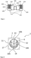
- FIG 1 shows a socket base 1 comprising a support ring 2 with a support ring frame 17 and a base base 100 with a base bottom 101, the support ring 2 comprising latching pins 5, which each have a first and second latching resistor 3, 4 and a connecting section 15, the base base 100 having guide receptacles 102 for said locking pins 5, wherein the guide receptacles 102 each have at least one first and/or at least one second locking recess 103, 104, the distance between the support ring frame 17 and the base bottom 101 being adjustable with said locking pins 5.
- the first base broad side 105 can be seen frontally, to which the first base narrow side 107 and opposite the second base narrow side 108 connect.
- the support ring has a support ring opening 6 for a socket cover. For reasons of clarity, some components that are usually installed in socket bases, such as spreading claws, are not explicitly shown. Those skilled in the art are sufficiently familiar with these components from the prior art.
- FIG. 2 shows the support ring 2, which has been turned over to show the locking pins 5 more clearly.
- the support ring 2 with the support ring frame 17 includes support ring recesses 9 for the installation and assembly of a device box. It includes a ring reinforcement 10, which connects to the support ring opening 6 and surrounds it.
- Two locking pins 5 each are connected by an intermediate reinforcement 16 .
- the four detent pins 5 each comprise a detent pin end 7, a connecting section 15, a first detent resistor 3 and a second detent resistor 4, the first detent resistor 3 being present at the detent pin end 7 and the second detent resistor 4 having a second detent resistor distance each spaced apart from the detent pin end 7. wherein the first latching resistance distance is less than the second latching resistance distance.
- the locking pins 5 each have an L-shaped sliding element 8, the locking resistors 3, 4 being connected to the sliding element 8 in one piece. It can also be seen that the lowering and/or inclination of the ring reinforcement 10 merges into the connecting section 15 in a straight line.
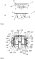
- figure 3 1 shows a support ring 2 with a support ring frame 17, the support ring 2 comprising locking pins 5, each of which has a locking pin end 7 and a first and second locking resistor 3, 4.
- the locking pins 5 each have an L-shaped sliding element 8, the locking resistors 3, 4 being connected to the sliding element 8 in one piece.
- the ring reinforcement 10 which extends in the direction of the locking pin ends 7 and from which the connecting section 15 of the locking pins 5 depart.
- Figure 3a shows a opposite Figure 3b ) 90° rotated view.
- figure 4 shows the base base with a first base broad side 105, an opposite second base broad side 106, a first base narrow side 107 and a second base narrow side 108, which extend between the base broad sides.
- Said two broad sides of the base each have two guide receptacles 102, 112 for locking pins.
- Each of the four guide receptacles 102, 112 has an outside first receptacle side 116 with first projections 109 and first contact surfaces 110.
- the two second receiving sides 117 of the first base broad side 105 do not have any projections like the other receiving sides. Instead, larger second contact surfaces 114 are provided here.
- each of the guide receptacles 102, 112 each includes a sliding groove 115 for receiving the sliding element 8, the sliding grooves 115 each including a side recess 120 and having an L-shaped cross section.
- the base includes a connection block 119 for spreader claws, which are Recesses defined by the connection block can be inserted.
- the first projections 109 and the first contact surfaces 110 each adjoin one another at an angle of 90° or enclose said angle.
- FIG 5 shows a perspective view of the socket base 100 from the direction of the first socket broad side 105.
- two first guide receptacles 102 can be seen, each with two, first latching recess 103 between first projections 109, with a first projection 109 between first latching recesses 103.
- the second guide receptacles 112 can be seen in guide receptacles 102 .
- the first guide receptacles 102 each include a second receptacle side, each of which has three second contact surfaces 114 , second latching recesses 104 of the first guide receptacles 102 extending between the second contact surfaces 114 .
- FIG 6 shows a perspective view of the socket base 1 comprising a support ring 2 with a support ring frame 17 and a base base 100 with a base bottom 101 and the connection block 119 for expanding claws.
- Two second latching recesses 104 can be seen, which are formed between second projections 111 , a second projection 111 being formed between second latching recesses 104 .
- figure 7 shows a side view of the base base 100 with a base bottom 101 from the direction of the second base broad side 106.
- the second guide receptacles 112 each comprise first receptacle sides 116 on the outside and second receptacle sides 118 on the inside.
- Two first latching recesses 103 are between three first projections 109 in each of the two first receptacle sides 116 educated.
- Two second latching recesses 104 are formed between three first projections 111 in the two second receiving sides 118, respectively.
- the first latching recess 103 is opposite the second latching recess 104 within the guide receptacles, with the latching recess spacing of the first latching recess 103 from the base 101 being smaller than the latching recess spacing of the opposite second latching recess 104 from the base 101. This feature has proven to be particularly beneficial for fine adjustment.
- FIG 8 shows a socket base 1 comprising a support ring 2 with a support ring frame 17 and a base base 100, the base base 100 comprising a first base broad side 105 and an opposite second base broad side 106, which are visible through the support ring opening 6.
- the support ring 2 is essentially rectangular and comprises a first support ring edge 11, an opposite second support ring edge 12, a third Support ring edge 13 and an opposite fourth support ring edge 14 defining said rectangular shape.
- FIG 9 shows socket base 1 with different distances between support ring frame 17 and base bottom 101, the distances being adjusted by shifting the locking pins.
- the socket base is designed and set up to be adjusted from a first state to either a second state or a third state, in particular also optionally to a fourth state, with the locking pin end having a first adjustment distance J1 from the base base in the first state, and in the second state state has a second adjustment distance J2 from the base floor, in the third state has a third adjustment distance J3 from the base floor and in the fourth state has a fourth adjustment distance J4 from the base floor, the first adjustment distance J1 being greater than the second adjustment distance J2, the second adjustment distance J2 being greater than the third adjustment distance J3 and the third adjustment distance J3 is greater than the fourth adjustment distance J4.
- the first adjustment distance J1 is in figure 9 a) shown, the second adjustment distance J2 is in Figure 9b ) shown, the third adjustment distance J3 in Figure 9 c) and the fourth adjustment distance J4 in Figure 9d) .
- the adjustment distances were determined orthogonal to the plane defined by the support ring frame.
- the recesses are opposite one another in some areas and are also arranged slightly offset in height from one another. This facilitates the fine adjustment of the distances J1, J2, J3 and J4 with an optimal arrangement of the cutouts.
Landscapes
- Snaps, Bayonet Connections, Set Pins, And Snap Rings (AREA)
- Connector Housings Or Holding Contact Members (AREA)
Priority Applications (4)
| Application Number | Priority Date | Filing Date | Title |
|---|---|---|---|
| DK18161211.0T DK3540871T3 (da) | 2018-03-12 | 2018-03-12 | Højdejusterbar stikdåsesokkel og stikdåse med denne sokkel |
| EP18161211.0A EP3540871B1 (de) | 2018-03-12 | 2018-03-12 | Höhenverstellbarer steckdosensockel und steckdose mit diesem steckdosensockel |
| PT181612110T PT3540871T (pt) | 2018-03-12 | 2018-03-12 | Tomada com base ajustável em altura e tomada com esta base de tomada |
| PL18161211.0T PL3540871T3 (pl) | 2018-03-12 | 2018-03-12 | Cokól gniazda wtykowego o regulowanej wysokości i gniazdo wtykowe z tym cokołem |
Applications Claiming Priority (1)
| Application Number | Priority Date | Filing Date | Title |
|---|---|---|---|
| EP18161211.0A EP3540871B1 (de) | 2018-03-12 | 2018-03-12 | Höhenverstellbarer steckdosensockel und steckdose mit diesem steckdosensockel |
Publications (2)
| Publication Number | Publication Date |
|---|---|
| EP3540871A1 EP3540871A1 (de) | 2019-09-18 |
| EP3540871B1 true EP3540871B1 (de) | 2023-06-07 |
Family
ID=61626963
Family Applications (1)
| Application Number | Title | Priority Date | Filing Date |
|---|---|---|---|
| EP18161211.0A Active EP3540871B1 (de) | 2018-03-12 | 2018-03-12 | Höhenverstellbarer steckdosensockel und steckdose mit diesem steckdosensockel |
Country Status (4)
| Country | Link |
|---|---|
| EP (1) | EP3540871B1 (da) |
| DK (1) | DK3540871T3 (da) |
| PL (1) | PL3540871T3 (da) |
| PT (1) | PT3540871T (da) |
Families Citing this family (2)
| Publication number | Priority date | Publication date | Assignee | Title |
|---|---|---|---|---|
| CN112821313A (zh) * | 2021-01-29 | 2021-05-18 | 中国十七冶集团有限公司 | 一种免螺丝可调接线盒 |
| CN120064774B (zh) * | 2025-01-15 | 2025-09-09 | 嘉兴众志机电有限公司 | 一种电力检测用绝缘电阻表 |
Family Cites Families (2)
| Publication number | Priority date | Publication date | Assignee | Title |
|---|---|---|---|---|
| DE7728676U1 (de) * | 1977-09-16 | 1977-12-22 | Gebrueder Merten Gmbh & Co Kg, 5270 Gummersbach | Tragorgan mit einem daran befestigten Gehäuse für ein Installationsgerät, insbesondere Helligkeitssteller |
| DE29911298U1 (de) * | 1999-06-29 | 2000-11-16 | Gira Giersiepen Gmbh & Co Kg, 42477 Radevormwald | Elektrisches Installationsgerät |
-
2018
- 2018-03-12 DK DK18161211.0T patent/DK3540871T3/da active
- 2018-03-12 PL PL18161211.0T patent/PL3540871T3/pl unknown
- 2018-03-12 PT PT181612110T patent/PT3540871T/pt unknown
- 2018-03-12 EP EP18161211.0A patent/EP3540871B1/de active Active
Also Published As
| Publication number | Publication date |
|---|---|
| DK3540871T3 (da) | 2023-09-18 |
| PL3540871T3 (pl) | 2023-12-11 |
| EP3540871A1 (de) | 2019-09-18 |
| PT3540871T (pt) | 2023-09-11 |
Similar Documents
| Publication | Publication Date | Title |
|---|---|---|
| EP2181550A1 (de) | Kabelverbindungseinrichtung und verbindungsvorrichtung mit derartigen kabelverbindungseinrichtungen | |
| DE3882421T2 (de) | Elektrischer Gerätesockel zum Aufstellen in einem Leitungsführungskanal. | |
| EP3480898A1 (de) | Modularer halterahmen für steckverbinder | |
| EP3843221A1 (de) | Halterahmen für einen steckverbinder | |
| EP3540871B1 (de) | Höhenverstellbarer steckdosensockel und steckdose mit diesem steckdosensockel | |
| DE102019109676A1 (de) | Haltefeder für Leuchte | |
| EP3608588B1 (de) | Haltefeder für leuchte | |
| DE3335820C2 (da) | ||
| EP3071896B1 (de) | Haltevorrichtung für ein gehäuse und verfahren zur montage des gehäuses unter verwendung der haltevorrichtung | |
| DE102006059863B3 (de) | Befestigungsvorrichtung zur Befestigung eines elektrischen oder elektronischen Geräts auf einer Hutschiene | |
| DE202014103387U1 (de) | Elektro-Installationssystem und Hohlwanddose zur Elektro-Installation | |
| DE102005052794B4 (de) | Halteelement zur Befestigung eines Abdeckrahmens eines Installationsgerätes | |
| EP2690729B1 (de) | Elektro-Installationssystem und Hohlwanddose zur Elektro-Installation | |
| DE102004059815B4 (de) | Montageträger für Unterflurdose | |
| EP3675300B1 (de) | Adapter zur positionierung und befestigung eines installationsgehäuses | |
| DE10054662A1 (de) | Einbaudose für die werkzeugfreie Montage | |
| DE102014014753A1 (de) | Halteeinrichtung für einen Querträger in einem elektrischen Schaltschrank und Schaltschrank | |
| DE69212395T2 (de) | Elektrische Anschlussleiste | |
| DE10227399B4 (de) | Elektrisches Installationsgerät mit Tragrahmen und mindestens einem an diesem befestigten Einsatz | |
| DE102024124552B3 (de) | Befestigungsanordnung zwischen einem Halter und einer Kabeltragkomponente sowie Halter mit einem daran angeschlossenen Anschlussadapter | |
| DE69617094T2 (de) | Befestigungsvorrichtung für einen Träger eines elektrischen Gerätekastens | |
| DE102012200315A1 (de) | Montagerahmen zum Einbau eines Kochfelds | |
| EP2690728A1 (de) | Hohlwanddose zur Elektro-Installation | |
| DE102010034862A1 (de) | Gerätedose für Installationsgeräte | |
| EP2953218B1 (de) | Halteeinrichtung für einen querträger in einem elektrischen schaltschrank und schaltschrank mit einer solchen einrichtung |
Legal Events
| Date | Code | Title | Description |
|---|---|---|---|
| PUAI | Public reference made under article 153(3) epc to a published international application that has entered the european phase |
Free format text: ORIGINAL CODE: 0009012 |
|
| STAA | Information on the status of an ep patent application or granted ep patent |
Free format text: STATUS: THE APPLICATION HAS BEEN PUBLISHED |
|
| AK | Designated contracting states |
Kind code of ref document: A1 Designated state(s): AL AT BE BG CH CY CZ DE DK EE ES FI FR GB GR HR HU IE IS IT LI LT LU LV MC MK MT NL NO PL PT RO RS SE SI SK SM TR |
|
| AX | Request for extension of the european patent |
Extension state: BA ME |
|
| STAA | Information on the status of an ep patent application or granted ep patent |
Free format text: STATUS: REQUEST FOR EXAMINATION WAS MADE |
|
| 17P | Request for examination filed |
Effective date: 20191128 |
|
| RBV | Designated contracting states (corrected) |
Designated state(s): AL AT BE BG CH CY CZ DE DK EE ES FI FR GB GR HR HU IE IS IT LI LT LU LV MC MK MT NL NO PL PT RO RS SE SI SK SM TR |
|
| STAA | Information on the status of an ep patent application or granted ep patent |
Free format text: STATUS: EXAMINATION IS IN PROGRESS |
|
| 17Q | First examination report despatched |
Effective date: 20201102 |
|
| GRAP | Despatch of communication of intention to grant a patent |
Free format text: ORIGINAL CODE: EPIDOSNIGR1 |
|
| STAA | Information on the status of an ep patent application or granted ep patent |
Free format text: STATUS: GRANT OF PATENT IS INTENDED |
|
| RIC1 | Information provided on ipc code assigned before grant |
Ipc: H02G 3/12 20060101ALN20220901BHEP Ipc: H01R 103/00 20060101ALN20220901BHEP Ipc: H01R 24/76 20110101AFI20220901BHEP |
|
| RIC1 | Information provided on ipc code assigned before grant |
Ipc: H02G 3/12 20060101ALN20220908BHEP Ipc: H01R 103/00 20060101ALN20220908BHEP Ipc: H01R 24/76 20110101AFI20220908BHEP |
|
| INTG | Intention to grant announced |
Effective date: 20220921 |
|
| GRAJ | Information related to disapproval of communication of intention to grant by the applicant or resumption of examination proceedings by the epo deleted |
Free format text: ORIGINAL CODE: EPIDOSDIGR1 |
|
| STAA | Information on the status of an ep patent application or granted ep patent |
Free format text: STATUS: EXAMINATION IS IN PROGRESS |
|
| INTC | Intention to grant announced (deleted) | ||
| GRAS | Grant fee paid |
Free format text: ORIGINAL CODE: EPIDOSNIGR3 |
|
| RIC1 | Information provided on ipc code assigned before grant |
Ipc: H02G 3/12 20060101ALN20221215BHEP Ipc: H01R 103/00 20060101ALN20221215BHEP Ipc: H01R 24/76 20110101AFI20221215BHEP |
|
| STAA | Information on the status of an ep patent application or granted ep patent |
Free format text: STATUS: GRANT OF PATENT IS INTENDED |
|
| GRAP | Despatch of communication of intention to grant a patent |
Free format text: ORIGINAL CODE: EPIDOSNIGR1 |
|
| RIC1 | Information provided on ipc code assigned before grant |
Ipc: H02G 3/12 20060101ALN20221222BHEP Ipc: H01R 103/00 20060101ALN20221222BHEP Ipc: H01R 24/76 20110101AFI20221222BHEP |
|
| INTG | Intention to grant announced |
Effective date: 20230126 |
|
| GRAA | (expected) grant |
Free format text: ORIGINAL CODE: 0009210 |
|
| STAA | Information on the status of an ep patent application or granted ep patent |
Free format text: STATUS: THE PATENT HAS BEEN GRANTED |
|
| AK | Designated contracting states |
Kind code of ref document: B1 Designated state(s): AL AT BE BG CH CY CZ DE DK EE ES FI FR GB GR HR HU IE IS IT LI LT LU LV MC MK MT NL NO PL PT RO RS SE SI SK SM TR |
|
| REG | Reference to a national code |
Ref country code: GB Ref legal event code: FG4D Free format text: NOT ENGLISH |
|
| P01 | Opt-out of the competence of the unified patent court (upc) registered |
Effective date: 20230403 |
|
| REG | Reference to a national code |
Ref country code: CH Ref legal event code: EP Ref country code: AT Ref legal event code: REF Ref document number: 1577734 Country of ref document: AT Kind code of ref document: T Effective date: 20230615 |
|
| REG | Reference to a national code |
Ref country code: DE Ref legal event code: R096 Ref document number: 502018012245 Country of ref document: DE |
|
| REG | Reference to a national code |
Ref country code: PT Ref legal event code: SC4A Ref document number: 3540871 Country of ref document: PT Date of ref document: 20230911 Kind code of ref document: T Free format text: AVAILABILITY OF NATIONAL TRANSLATION Effective date: 20230906 |
|
| REG | Reference to a national code |
Ref country code: DK Ref legal event code: T3 Effective date: 20230911 |
|
| REG | Reference to a national code |
Ref country code: NL Ref legal event code: FP |
|
| REG | Reference to a national code |
Ref country code: LT Ref legal event code: MG9D |
|
| PG25 | Lapsed in a contracting state [announced via postgrant information from national office to epo] |
Ref country code: SE Free format text: LAPSE BECAUSE OF FAILURE TO SUBMIT A TRANSLATION OF THE DESCRIPTION OR TO PAY THE FEE WITHIN THE PRESCRIBED TIME-LIMIT Effective date: 20230607 Ref country code: NO Free format text: LAPSE BECAUSE OF FAILURE TO SUBMIT A TRANSLATION OF THE DESCRIPTION OR TO PAY THE FEE WITHIN THE PRESCRIBED TIME-LIMIT Effective date: 20230907 Ref country code: ES Free format text: LAPSE BECAUSE OF FAILURE TO SUBMIT A TRANSLATION OF THE DESCRIPTION OR TO PAY THE FEE WITHIN THE PRESCRIBED TIME-LIMIT Effective date: 20230607 |
|
| PG25 | Lapsed in a contracting state [announced via postgrant information from national office to epo] |
Ref country code: RS Free format text: LAPSE BECAUSE OF FAILURE TO SUBMIT A TRANSLATION OF THE DESCRIPTION OR TO PAY THE FEE WITHIN THE PRESCRIBED TIME-LIMIT Effective date: 20230607 Ref country code: LV Free format text: LAPSE BECAUSE OF FAILURE TO SUBMIT A TRANSLATION OF THE DESCRIPTION OR TO PAY THE FEE WITHIN THE PRESCRIBED TIME-LIMIT Effective date: 20230607 Ref country code: LT Free format text: LAPSE BECAUSE OF FAILURE TO SUBMIT A TRANSLATION OF THE DESCRIPTION OR TO PAY THE FEE WITHIN THE PRESCRIBED TIME-LIMIT Effective date: 20230607 Ref country code: HR Free format text: LAPSE BECAUSE OF FAILURE TO SUBMIT A TRANSLATION OF THE DESCRIPTION OR TO PAY THE FEE WITHIN THE PRESCRIBED TIME-LIMIT Effective date: 20230607 Ref country code: GR Free format text: LAPSE BECAUSE OF FAILURE TO SUBMIT A TRANSLATION OF THE DESCRIPTION OR TO PAY THE FEE WITHIN THE PRESCRIBED TIME-LIMIT Effective date: 20230908 |
|
| PG25 | Lapsed in a contracting state [announced via postgrant information from national office to epo] |
Ref country code: FI Free format text: LAPSE BECAUSE OF FAILURE TO SUBMIT A TRANSLATION OF THE DESCRIPTION OR TO PAY THE FEE WITHIN THE PRESCRIBED TIME-LIMIT Effective date: 20230607 |
|
| PG25 | Lapsed in a contracting state [announced via postgrant information from national office to epo] |
Ref country code: SK Free format text: LAPSE BECAUSE OF FAILURE TO SUBMIT A TRANSLATION OF THE DESCRIPTION OR TO PAY THE FEE WITHIN THE PRESCRIBED TIME-LIMIT Effective date: 20230607 |
|
| PG25 | Lapsed in a contracting state [announced via postgrant information from national office to epo] |
Ref country code: IS Free format text: LAPSE BECAUSE OF FAILURE TO SUBMIT A TRANSLATION OF THE DESCRIPTION OR TO PAY THE FEE WITHIN THE PRESCRIBED TIME-LIMIT Effective date: 20231007 |
|
| PG25 | Lapsed in a contracting state [announced via postgrant information from national office to epo] |
Ref country code: SM Free format text: LAPSE BECAUSE OF FAILURE TO SUBMIT A TRANSLATION OF THE DESCRIPTION OR TO PAY THE FEE WITHIN THE PRESCRIBED TIME-LIMIT Effective date: 20230607 Ref country code: SK Free format text: LAPSE BECAUSE OF FAILURE TO SUBMIT A TRANSLATION OF THE DESCRIPTION OR TO PAY THE FEE WITHIN THE PRESCRIBED TIME-LIMIT Effective date: 20230607 Ref country code: RO Free format text: LAPSE BECAUSE OF FAILURE TO SUBMIT A TRANSLATION OF THE DESCRIPTION OR TO PAY THE FEE WITHIN THE PRESCRIBED TIME-LIMIT Effective date: 20230607 Ref country code: IS Free format text: LAPSE BECAUSE OF FAILURE TO SUBMIT A TRANSLATION OF THE DESCRIPTION OR TO PAY THE FEE WITHIN THE PRESCRIBED TIME-LIMIT Effective date: 20231007 Ref country code: EE Free format text: LAPSE BECAUSE OF FAILURE TO SUBMIT A TRANSLATION OF THE DESCRIPTION OR TO PAY THE FEE WITHIN THE PRESCRIBED TIME-LIMIT Effective date: 20230607 |
|
| REG | Reference to a national code |
Ref country code: DE Ref legal event code: R097 Ref document number: 502018012245 Country of ref document: DE |
|
| PLBE | No opposition filed within time limit |
Free format text: ORIGINAL CODE: 0009261 |
|
| STAA | Information on the status of an ep patent application or granted ep patent |
Free format text: STATUS: NO OPPOSITION FILED WITHIN TIME LIMIT |
|
| PG25 | Lapsed in a contracting state [announced via postgrant information from national office to epo] |
Ref country code: SI Free format text: LAPSE BECAUSE OF FAILURE TO SUBMIT A TRANSLATION OF THE DESCRIPTION OR TO PAY THE FEE WITHIN THE PRESCRIBED TIME-LIMIT Effective date: 20230607 |
|
| 26N | No opposition filed |
Effective date: 20240308 |
|
| PG25 | Lapsed in a contracting state [announced via postgrant information from national office to epo] |
Ref country code: SI Free format text: LAPSE BECAUSE OF FAILURE TO SUBMIT A TRANSLATION OF THE DESCRIPTION OR TO PAY THE FEE WITHIN THE PRESCRIBED TIME-LIMIT Effective date: 20230607 |
|
| REG | Reference to a national code |
Ref country code: CH Ref legal event code: PL |
|
| PG25 | Lapsed in a contracting state [announced via postgrant information from national office to epo] |
Ref country code: BG Free format text: LAPSE BECAUSE OF FAILURE TO SUBMIT A TRANSLATION OF THE DESCRIPTION OR TO PAY THE FEE WITHIN THE PRESCRIBED TIME-LIMIT Effective date: 20230607 |
|
| PG25 | Lapsed in a contracting state [announced via postgrant information from national office to epo] |
Ref country code: LU Free format text: LAPSE BECAUSE OF NON-PAYMENT OF DUE FEES Effective date: 20240312 |
|
| PG25 | Lapsed in a contracting state [announced via postgrant information from national office to epo] |
Ref country code: MC Free format text: LAPSE BECAUSE OF FAILURE TO SUBMIT A TRANSLATION OF THE DESCRIPTION OR TO PAY THE FEE WITHIN THE PRESCRIBED TIME-LIMIT Effective date: 20230607 |
|
| GBPC | Gb: european patent ceased through non-payment of renewal fee |
Effective date: 20240312 |
|
| PG25 | Lapsed in a contracting state [announced via postgrant information from national office to epo] |
Ref country code: MC Free format text: LAPSE BECAUSE OF FAILURE TO SUBMIT A TRANSLATION OF THE DESCRIPTION OR TO PAY THE FEE WITHIN THE PRESCRIBED TIME-LIMIT Effective date: 20230607 Ref country code: LU Free format text: LAPSE BECAUSE OF NON-PAYMENT OF DUE FEES Effective date: 20240312 Ref country code: BG Free format text: LAPSE BECAUSE OF FAILURE TO SUBMIT A TRANSLATION OF THE DESCRIPTION OR TO PAY THE FEE WITHIN THE PRESCRIBED TIME-LIMIT Effective date: 20230607 |
|
| PG25 | Lapsed in a contracting state [announced via postgrant information from national office to epo] |
Ref country code: GB Free format text: LAPSE BECAUSE OF NON-PAYMENT OF DUE FEES Effective date: 20240312 |
|
| PG25 | Lapsed in a contracting state [announced via postgrant information from national office to epo] |
Ref country code: IE Free format text: LAPSE BECAUSE OF NON-PAYMENT OF DUE FEES Effective date: 20240312 |
|
| PG25 | Lapsed in a contracting state [announced via postgrant information from national office to epo] |
Ref country code: IE Free format text: LAPSE BECAUSE OF NON-PAYMENT OF DUE FEES Effective date: 20240312 Ref country code: GB Free format text: LAPSE BECAUSE OF NON-PAYMENT OF DUE FEES Effective date: 20240312 Ref country code: CH Free format text: LAPSE BECAUSE OF NON-PAYMENT OF DUE FEES Effective date: 20240331 |
|
| PG25 | Lapsed in a contracting state [announced via postgrant information from national office to epo] |
Ref country code: CY Free format text: LAPSE BECAUSE OF FAILURE TO SUBMIT A TRANSLATION OF THE DESCRIPTION OR TO PAY THE FEE WITHIN THE PRESCRIBED TIME-LIMIT; INVALID AB INITIO Effective date: 20180312 |
|
| PG25 | Lapsed in a contracting state [announced via postgrant information from national office to epo] |
Ref country code: HU Free format text: LAPSE BECAUSE OF FAILURE TO SUBMIT A TRANSLATION OF THE DESCRIPTION OR TO PAY THE FEE WITHIN THE PRESCRIBED TIME-LIMIT; INVALID AB INITIO Effective date: 20180312 |
|
| PG25 | Lapsed in a contracting state [announced via postgrant information from national office to epo] |
Ref country code: TR Free format text: LAPSE BECAUSE OF FAILURE TO SUBMIT A TRANSLATION OF THE DESCRIPTION OR TO PAY THE FEE WITHIN THE PRESCRIBED TIME-LIMIT Effective date: 20230607 |
|
| PGFP | Annual fee paid to national office [announced via postgrant information from national office to epo] |
Ref country code: DE Payment date: 20260320 Year of fee payment: 9 Ref country code: DK Payment date: 20260323 Year of fee payment: 9 |
|
| PGFP | Annual fee paid to national office [announced via postgrant information from national office to epo] |
Ref country code: AT Payment date: 20260318 Year of fee payment: 9 |
|
| PGFP | Annual fee paid to national office [announced via postgrant information from national office to epo] |
Ref country code: BE Payment date: 20260323 Year of fee payment: 9 Ref country code: IT Payment date: 20260320 Year of fee payment: 9 |
|
| PGFP | Annual fee paid to national office [announced via postgrant information from national office to epo] |
Ref country code: NL Payment date: 20260323 Year of fee payment: 9 |
|
| PGFP | Annual fee paid to national office [announced via postgrant information from national office to epo] |
Ref country code: FR Payment date: 20260323 Year of fee payment: 9 |
|
| PGFP | Annual fee paid to national office [announced via postgrant information from national office to epo] |
Ref country code: CZ Payment date: 20260227 Year of fee payment: 9 Ref country code: PT Payment date: 20260219 Year of fee payment: 9 |
|
| PGFP | Annual fee paid to national office [announced via postgrant information from national office to epo] |
Ref country code: PL Payment date: 20260213 Year of fee payment: 9 |