EP3540889A1 - Überwachungsvorrichtung, erdschlussschutzschaltung und verfahren - Google Patents
Überwachungsvorrichtung, erdschlussschutzschaltung und verfahren Download PDFInfo
- Publication number
- EP3540889A1 EP3540889A1 EP19163281.9A EP19163281A EP3540889A1 EP 3540889 A1 EP3540889 A1 EP 3540889A1 EP 19163281 A EP19163281 A EP 19163281A EP 3540889 A1 EP3540889 A1 EP 3540889A1
- Authority
- EP
- European Patent Office
- Prior art keywords
- neutral grounding
- ground end
- grounding resistor
- injection signal
- signal generator
- Prior art date
- Legal status (The legal status is an assumption and is not a legal conclusion. Google has not performed a legal analysis and makes no representation as to the accuracy of the status listed.)
- Pending
Links
- 238000000034 method Methods 0.000 title claims description 10
- 230000007935 neutral effect Effects 0.000 claims abstract description 144
- 238000002347 injection Methods 0.000 claims abstract description 81
- 239000007924 injection Substances 0.000 claims abstract description 81
- 239000003990 capacitor Substances 0.000 claims description 27
- 238000012544 monitoring process Methods 0.000 description 5
- 238000005259 measurement Methods 0.000 description 4
- 239000000523 sample Substances 0.000 description 4
- 230000015556 catabolic process Effects 0.000 description 3
- 230000007274 generation of a signal involved in cell-cell signaling Effects 0.000 description 3
- 238000009434 installation Methods 0.000 description 3
- 230000003071 parasitic effect Effects 0.000 description 3
- 230000010363 phase shift Effects 0.000 description 3
- 238000012937 correction Methods 0.000 description 2
- 230000005284 excitation Effects 0.000 description 2
- 230000008569 process Effects 0.000 description 2
- 230000004075 alteration Effects 0.000 description 1
- 230000000903 blocking effect Effects 0.000 description 1
- 239000004020 conductor Substances 0.000 description 1
- 230000008878 coupling Effects 0.000 description 1
- 238000010168 coupling process Methods 0.000 description 1
- 238000005859 coupling reaction Methods 0.000 description 1
- 238000006731 degradation reaction Methods 0.000 description 1
- 230000006870 function Effects 0.000 description 1
- 238000012986 modification Methods 0.000 description 1
- 230000004048 modification Effects 0.000 description 1
- 238000012545 processing Methods 0.000 description 1
- 230000000644 propagated effect Effects 0.000 description 1
- 238000010845 search algorithm Methods 0.000 description 1
Images



Classifications
-
- H—ELECTRICITY
- H02—GENERATION; CONVERSION OR DISTRIBUTION OF ELECTRIC POWER
- H02H—EMERGENCY PROTECTIVE CIRCUIT ARRANGEMENTS
- H02H1/00—Details of emergency protective circuit arrangements
- H02H1/0007—Details of emergency protective circuit arrangements concerning the detecting means
- H02H1/003—Fault detection by injection of an auxiliary voltage
-
- G—PHYSICS
- G01—MEASURING; TESTING
- G01R—MEASURING ELECTRIC VARIABLES; MEASURING MAGNETIC VARIABLES
- G01R31/00—Arrangements for testing electric properties; Arrangements for locating electric faults; Arrangements for electrical testing characterised by what is being tested not provided for elsewhere
- G01R31/50—Testing of electric apparatus, lines, cables or components for short-circuits, continuity, leakage current or incorrect line connections
-
- H—ELECTRICITY
- H02—GENERATION; CONVERSION OR DISTRIBUTION OF ELECTRIC POWER
- H02H—EMERGENCY PROTECTIVE CIRCUIT ARRANGEMENTS
- H02H3/00—Emergency protective circuit arrangements for automatic disconnection directly responsive to an undesired change from normal electric working condition with or without subsequent reconnection ; integrated protection
- H02H3/16—Emergency protective circuit arrangements for automatic disconnection directly responsive to an undesired change from normal electric working condition with or without subsequent reconnection ; integrated protection responsive to fault current to earth, frame or mass
-
- H—ELECTRICITY
- H02—GENERATION; CONVERSION OR DISTRIBUTION OF ELECTRIC POWER
- H02H—EMERGENCY PROTECTIVE CIRCUIT ARRANGEMENTS
- H02H3/00—Emergency protective circuit arrangements for automatic disconnection directly responsive to an undesired change from normal electric working condition with or without subsequent reconnection ; integrated protection
- H02H3/26—Emergency protective circuit arrangements for automatic disconnection directly responsive to an undesired change from normal electric working condition with or without subsequent reconnection ; integrated protection responsive to difference between voltages or between currents; responsive to phase angle between voltages or between currents
- H02H3/32—Emergency protective circuit arrangements for automatic disconnection directly responsive to an undesired change from normal electric working condition with or without subsequent reconnection ; integrated protection responsive to difference between voltages or between currents; responsive to phase angle between voltages or between currents involving comparison of the voltage or current values at corresponding points in different conductors of a single system, e.g. of currents in go and return conductors
- H02H3/33—Emergency protective circuit arrangements for automatic disconnection directly responsive to an undesired change from normal electric working condition with or without subsequent reconnection ; integrated protection responsive to difference between voltages or between currents; responsive to phase angle between voltages or between currents involving comparison of the voltage or current values at corresponding points in different conductors of a single system, e.g. of currents in go and return conductors using summation current transformers
- H02H3/331—Emergency protective circuit arrangements for automatic disconnection directly responsive to an undesired change from normal electric working condition with or without subsequent reconnection ; integrated protection responsive to difference between voltages or between currents; responsive to phase angle between voltages or between currents involving comparison of the voltage or current values at corresponding points in different conductors of a single system, e.g. of currents in go and return conductors using summation current transformers responsive to earthing of the neutral conductor
-
- H—ELECTRICITY
- H02—GENERATION; CONVERSION OR DISTRIBUTION OF ELECTRIC POWER
- H02H—EMERGENCY PROTECTIVE CIRCUIT ARRANGEMENTS
- H02H5/00—Emergency protective circuit arrangements for automatic disconnection directly responsive to an undesired change from normal non-electric working conditions with or without subsequent reconnection
- H02H5/10—Emergency protective circuit arrangements for automatic disconnection directly responsive to an undesired change from normal non-electric working conditions with or without subsequent reconnection responsive to mechanical injury, e.g. rupture of line, breakage of earth connection
- H02H5/105—Emergency protective circuit arrangements for automatic disconnection directly responsive to an undesired change from normal non-electric working conditions with or without subsequent reconnection responsive to mechanical injury, e.g. rupture of line, breakage of earth connection responsive to deterioration or interruption of earth connection
-
- H—ELECTRICITY
- H02—GENERATION; CONVERSION OR DISTRIBUTION OF ELECTRIC POWER
- H02H—EMERGENCY PROTECTIVE CIRCUIT ARRANGEMENTS
- H02H9/00—Emergency protective circuit arrangements for limiting excess current or voltage without disconnection
- H02H9/08—Limitation or suppression of earth fault currents, e.g. Petersen coil
Definitions
- Embodiments relate to the field of protection devices, an in particular, to neutral grounding resistors.
- Ground fault resistors may be used in conjunction with resistance grounded power systems.
- a neutral grounding resistor may be deployed under conditions where a ground fault is to be limited to a predetermined current.
- Neutral grounding resistors may also be accompanied by a monitor to monitor when degradation of neutral grounding resistor may take place. In some jurisdictions, monitoring of neutral grounding resistors is required during all operation phases for changes in resistance value.
- a fault protection arrangement including a neutral grounding resistor, comprising a ground end and a non-ground end.
- the fault protection arrangement may include a neutral grounding resistance monitor assembly, coupled to the neutral grounding resistor, where the neutral grounding resistance monitor includes a sense circuit, coupled to the ground end of the neutral grounding resistor, and an injection signal generator, arranged to generate a frequency of 240 Hz or greater.
- a fault protection arrangement may include a neutral grounding resistor, comprising a ground end and a non-ground end, and a neutral grounding resistance monitor assembly, coupled to the neutral grounding resistor.
- the neutral grounding resistance monitor assembly may include a sense circuit, coupled to the non-ground end of the neutral grounding resistor; and an injection signal generator, coupled to the ground end of the neutral grounding resistor and arranged to generate a frequency of 240 Hz or greater.
- a fault protection method may include providing a neutral grounding resistor, having a ground end, coupled to ground, and a non-ground end, and generating, by an injection signal generator, an injection signal having an injection signal frequency, above 240 Hz, wherein the injection signal travels to the neutral grounding resistor along at the non-ground end.
- the fault protection method may further include sensing a resistance of the neutral grounding resistor using a sense circuit, electrically coupled between the ground end of the neutral grounding resistor and the injection signal generator.
- the terms “on,” “overlying” ,”disposed on” and “over” may be used in the following description and claims. “On” ,”overlying”, “disposed on” and “over” may be used to indicate that two or more elements are in direct physical contact with one another. Also, the term “on”, “overlying” ,”disposed on” and “over”, may mean that two or more elements are not in direct contact with one another. For example, “over” may mean that one element is above another element while not contacting one another and may have another element or elements in between the two elements.
- FIG. 1A shows a fault protection arrangement 10 according to various embodiments of the disclosure.
- the fault protection arrangement 10 may include a neutral grounding resistor 18, where the neutral grounding resistor has a ground end and a non-ground end. While not shown, the non-ground end may be coupled to a power system, or other component or equipment to be protected.
- the neutral grounding resistor 18 is designed to present a fixed electrical resistance, to treat a given fault energy received, for example, over a line between the neutral grounding resistor and power system (not shown).
- the neutral grounding resistor 18 may be coupled to the neutral of a power system to limit fault current, providing a path for grounding current to a transformer neutral. Excessive changes in the resistance value of the neutral grounding resistor 18 may cause harm to a system being protected.
- the fault protection arrangement 10 provides monitoring and control to determine the state of the neutral grounding resistor 18.
- the fault protection arrangement 10 may include a neutral grounding resistance monitor assembly 12, coupled to the neutral grounding resistor 18.
- the neutral grounding resistance monitor assembly 12 may function to monitor the neutral grounding resistor 18, so as to detect changes in the neutral grounding resistor, such as changes in resistance.
- the monitoring may be performed in an intermittent, semicontinuous, or continuous fashion, so as to detect changes in resistance in a timely fashion, to allow the fault protection arrangement to alarm or shut down a power system as necessary, without causing harm.
- the fault protection arrangement 10, and in particular, the neutral grounding resistance monitor assembly 12 may include a sense circuit 16, coupled to the ground end of the neutral grounding resistor 18, as well as an injection signal generator 14.
- the sense circuit 16 and injection signal generator 14, as well as auxiliary components may be arranged in different configurations to provide effective monitoring of the neutral grounding resistor 18.
- the injection signal generator 14 may be arranged to generate an alternating current signal (AC signal), operating at a signal frequency of 240 Hz or higher, and in some non-limiting embodiments, operating at hundreds of kHz, or megahertz.
- the injection signal generator 14 may include or may accompany a signal processing circuit, according to embodiments of the disclosure.
- the sense circuit 16 and injection signal generator 14 may operate together as a neutral grounding resistor monitor for the neutral grounding resistor 18.
- the neutral grounding resistance monitor assembly 12 further arranges the injection signal generator 14 to be coupled on a first side to the non-ground end of the neutral grounding resistor 18, and on a second side to the sense circuit 16.
- the neutral grounding resistance monitor assembly 12 further comprises an injection capacitor 20, coupled in electrical series between the injection signal generator 14 and the non-ground end of the neutral grounding resistor 18.
- the neutral grounding resistance monitor assembly 12 further comprises a sense resistor 22, coupled in electrical series between the sense circuit 16 and the ground end of the neutral grounding resistor 18.
- the injection signal generator 14 may operate below approximately 1 MHz in some embodiments.
- a high frequency signal of any suitable waveform is sent by the injection signal generator 14 to the neutral grounding resistor 18 along an electrical path including the injection capacitor 20.
- the injection signal generator may include logic and circuitry, embodied in any combination of software and hardware, to modify the waveform shape, as well as to scan an installation with a frequency sweep to determine optimal frequency and installation parasitic losses.
- a search algorithm may be implemented to find optimal frequencies for the system installation.
- the injection capacitor 20 may be sized to exhibit an appropriate capacitance and breakdown voltage according to the system to be protected. Particularly, the injection capacitor 20 may exhibit a capacitance of hundreds of picoFarads, nanoFarads, to hundreds of nanoFarads. By use of suitable capacitance for the injection capacitor 20 at an appropriate probe frequency, such as 300 kHz, small changes in impedance of the neutral grounding resistor 18 may be ascertained, as detailed in the embodiments to follow.
- an injection capacitor 20 may be implemented in different configurations, including a coaxial arrangement of conductors, a parallel plate capacitor, a multilayer capacitor, such as in a printed circuit board, or other known capacitor. The embodiments are not limited in this context.
- the frequency of the injection signal generator 14 may range from 240 Hz to 10 MHz, while the edge rate range from 240 Hz to 10 GHz.
- the repetition rate may range from 100 kHz to 5 MHz, while the edge rate ranges from 100 kHz to 1 GHz.
- the signals generated by injection signal generator 14 may be used to probe resistance of a neutral grounding resistor in open state, short circuit state, or a changing value under normal operation.
- system inductance, NGR inductance, connection inductance, system capacitance, NGR capacitance, and connection capacitance may be probed by the signals.
- the injection signal generator 14 may be coupled to an alarm circuit (not shown), to generate an alarm signal when the resistance of the neutral grounding resistor 18 falls outside of a predetermined range.
- the neutral grounding resistance monitor assembly 12 may further include a sense resistor 22, coupled in electrical series between the sense circuit 16 and the ground end of the neutral grounding resistor 18.
- impedance may be determined according to the simple relation V/I, providing greater accuracy.
- FIG. 1B shows a protection arrangement 100 according to various embodiments of the disclosure.
- an injection signal generator and sense circuit are coupled to a non-ground end of a neutral grounding resistor.
- the protection arrangement 100 involves a neutral grounding resistor 102, electrically coupled to ground and coupled to a power system 130.
- the power system 130 may include various known components including transformers and other equipment.
- the neutral grounding resistor 102 may be designed to provide a target resistance over any suitable range, such as 10 ⁇ to thousands of ⁇ . The embodiments are not limited in this context.
- the neutral grounding resistor 102 is designed to present a fixed electrical resistance, to treat a given fault energy received, for example, over a line between the neutral grounding resistor and power system 130.
- the neutral grounding resistor 102 may be coupled to the neutral of a power system to limit fault current, providing a path for grounding current to a transformer neutral. Excessive changes in the resistance value of the neutral grounding resistor 102 may cause harm to a system being protected.
- the protection arrangement 100 provides monitoring and control to determine the state of the neutral grounding resistor 102.
- the protection arrangement 100 includes a sense circuit 110 and signal generation circuit 120, acting as a monitor for the neutral grounding resistor 102.
- the signal generation circuit 120 may include injection signal generator 122, while the sense circuit includes capacitor 112.
- the injection signal generator 122 may operate at the kHz to GHz range in various non-limiting embodiments.
- the injection signal generator 122 may operate below approximately 1 MHz in some embodiments.
- a high frequency signal of any suitable waveform is sent by the injection signal generator 122 to the neutral grounding resistor 102 along an electrical path including the capacitor 112.
- the capacitor 112 may be sized to exhibit an appropriate capacitance and breakdown voltage according to the system to be protected.
- the capacitor 112 may exhibit a capacitance of hundreds of picoFarads, nanoFarads, to hundreds of nanoFarads.
- suitable capacitance for the capacitor 112 at an appropriate probe frequency such as 300 kHz, small changes in impedance of the neutral ground resistor 102 may be ascertained, as detailed in the embodiments to follow.
- the repetition frequency of the injection signal generator 122 may range from 240 Hz to 10 MHz, while the edge rate range from 240 Hz to 10 GHz. In particular embodiments, the repetition rate may range from 100 kHz to 5 MHz, while the edge rate ranged from 100 kHz to 1 GHz.
- the signals generated by injection signal generator 122 may be used to probe resistance of a neutral grounding resistor in open state, short circuit state, or a changing value under normal operation.
- system inductance, NGR inductance, connection inductance, system capacitance, NGR capacitance, and connection capacitance may be probed by the signals.
- the signal generation circuit may further include an alarm circuit 124, to generate an alarm signal when the resistance of the neutral grounding resistor 102 falls outside of a predetermined range.
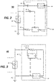
- fault protection arrangement 30 includes a neutral grounding resistor monitor assembly 32, having a similar arrangement to that of FIG. 1A .
- the neutral grounding resistor monitor assembly 32 includes a sense capacitor 24, coupled in electrical series between the sense circuit 16 and the non-ground end of the neutral grounding resistor 18.
- This arrangement allows for a more accurate voltage measurement.
- the improved accuracy is achieved by removing the phase shift provided by the injection capacitor 20.
- the phase shift in the injection capacitor 20 is created by virtue of the current of the excitation signal emitted by the injection signal generator 14.
- the configuration of FIG. 2 removes the equivalent series resistance(ESR) of injection capacitor 20 from the neutral grounding resistor measurement.
- ESR equivalent series resistance
- a known injection capacitor may exhibit 104 Ohms ESR at 150 kHz excitation frequency, comparable to a common resistance value of a neutral grounding resistor, in the range of 10 Ohm to 1000 Ohm.
- FIG. 3 there is shown another fault protection arrangement, shown as fault protection arrangement 40, in accordance with further embodiments of the disclosure.
- a neutral grounding resistance monitor assembly 42 is provided with similar components to the components of the arrangement of FIG. 1A .
- the sense circuit 16 is coupled to the non-ground end of the neutral grounding resistor 18, instead of the ground end.
- the injection signal generator 14 is coupled to the ground end of the neutral grounding resistor 18, instead of the non-ground end.
- a resistor 44 is provided in electrical series between a first end of the injection signal generator 14 and the non-ground end of the neutral grounding resistor 18.
- a fault protection arrangement 50 is also arranged to be electrically parallel to the sense circuit 16, which circuit is also arranged in electrical series between the first end of the injection signal generator 14 and the non-ground end of the neutral grounding resistor 18.
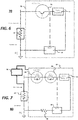
- a neutral grounding resistance monitor assembly 52 includes a similar arrangement of components to neutral grounding resistance monitor assembly 42, with the addition of an injection capacitor 54, disposed in electrical series between the injection signal generator 14 and the ground end of the neutral grounding resistor 18.
- FIG. 5 depicts one such embodiment of a fault protection arrangement 60.
- a neutral grounding resistance monitor assembly 62 is provided including a transformer 64, where the sense circuit 16 is arranged in electrical series on a first side of the transformer 64 , between the transformer 64 and the ground end of the neutral grounding resistor 18.
- the injection signal generator 14 is arranged on a second side of the transformer.
- FIG. 6 depicts another embodiment of a fault protection arrangement 70, according to further embodiments of the disclosure.
- a neutral grounding resistance monitor assembly 72 is provided including a first transistor 74, arranged in electrical series between the injection signal generator 14 and the non-ground end of the neutral grounding resistor18.
- the first transistor 74 may be arranged as a high voltage transistor.
- FIG. 7 depicts another embodiment of a fault protection arrangement 80, according to further embodiments of the disclosure.
- a sense resistor 88 is provided in electrical series between the sense circuit 16 and ground end of the neutral grounding resistor 18 in the neutral grounding resistance monitor assembly 82.
- a transistor assembly is provided in electrical series between the non-ground end of the neutral grounding resistor 18 and the injection signal generator 14.
- the transistor assembly is shown as a first transistor 84 and a second transistor 86, arranged in electrical series between the non-ground end of the neutral grounding resistor 18 and the injection signal generator 14.
- the fault protection arrangement 80 may include a control circuit 90, coupled to the neutral grounding resistor 18 and the neutral grounding resistance monitor assembly 82.
- the control circuit 90 may measure the presence of a ground fault condition, as in known systems. At the inception of a fault, the control circuit 90 may send a signal to ensure the transistor assembly is not in an ON state, preventing damage to the first transistor 84 and second transistor 86. Notably, this two-transistor configuration defeats the limitation of a single transistor configuration with a parasitic body diode. In operation, both the first transistor 84 and the second transistor 86 may be turned on and off at the same time.
- the first transistor 84 and the second transistor 86 are arranged in a manner that the respective parasitic diodes formed, are placed in an anode-to-anode configuration as shown (or alternatively in a cathode-to cathode configuration), allowing an AC signal to be propagated from the injection signal generator 14 to the neutral grounding resistor, while blocking many thousands of volts in the off state.
- the fault protection arrangement 80 may be operated such that the first transistor 84 and second transistor 86 are turned on just for a few milliseconds or so, at intervals such as 1 second, 2 seconds, 5 seconds, or other interval, generally less than 10 seconds, so that timely information is provided as to the resistance of the neutral grounding resistor 18.
- FIG. 8 depicts an exemplary process flow 800.
- a power system is connected to a fault protection arrangement.
- the fault protection arrangement may include a neutral grounding resistor, the neutral grounding resistor comprising a ground end and a non-ground end; a sense circuit, coupled to the non-ground end of the neutral grounding resistor, the sense circuit comprising a sense resistor, and an injection capacitor; and an injection signal generator, coupled to the non-ground end of the neutral grounding resistor.
- a resistance of the neutral grounding resistor is probed by sending an injection signal from the sense circuit to the neutral grounding resistor through the non-ground end to ground end, and through to sense circuit, coupled to ground end.
- the present embodiments provide components, circuit arrangements and techniques to conveniently monitor small changes in resistance, such as in neutral grounding resistors.
- One or more components of a neutral grounding resistor monitor assembly are coupled to the ground end of the neutral grounding resistor in accordance with various embodiments.
Landscapes
- Physics & Mathematics (AREA)
- General Physics & Mathematics (AREA)
- Engineering & Computer Science (AREA)
- Power Engineering (AREA)
- Testing Of Short-Circuits, Discontinuities, Leakage, Or Incorrect Line Connections (AREA)
- Emergency Protection Circuit Devices (AREA)
Applications Claiming Priority (2)
| Application Number | Priority Date | Filing Date | Title |
|---|---|---|---|
| US201862644359P | 2018-03-16 | 2018-03-16 | |
| US16/297,501 US11539200B2 (en) | 2018-03-16 | 2019-03-08 | Monitor device, ground fault protection circuit and techniques |
Publications (1)
| Publication Number | Publication Date |
|---|---|
| EP3540889A1 true EP3540889A1 (de) | 2019-09-18 |
Family
ID=65818237
Family Applications (1)
| Application Number | Title | Priority Date | Filing Date |
|---|---|---|---|
| EP19163281.9A Pending EP3540889A1 (de) | 2018-03-16 | 2019-03-15 | Überwachungsvorrichtung, erdschlussschutzschaltung und verfahren |
Country Status (4)
| Country | Link |
|---|---|
| US (1) | US11539200B2 (de) |
| EP (1) | EP3540889A1 (de) |
| AU (1) | AU2019201770B2 (de) |
| CA (1) | CA3036732A1 (de) |
Families Citing this family (3)
| Publication number | Priority date | Publication date | Assignee | Title |
|---|---|---|---|---|
| WO2019229744A1 (en) * | 2018-05-28 | 2019-12-05 | Shkury Ezra | Ground monitoring tester |
| CN111650533B (zh) * | 2020-06-15 | 2022-08-23 | 国家电网有限公司 | 一种转子磁极接地点查找仪的查找方法 |
| CN115693630B (zh) * | 2023-01-05 | 2023-04-25 | 国网山西省电力公司朔州供电公司 | 一种基于分裂绕组的混合型熄弧系统及其工作方法 |
Citations (5)
| Publication number | Priority date | Publication date | Assignee | Title |
|---|---|---|---|---|
| DE2458530A1 (de) * | 1974-11-14 | 1976-05-20 | Bbc Brown Boveri & Cie | Erdschluss-ueberwachungseinrichtung |
| EP0360109A1 (de) * | 1988-09-21 | 1990-03-28 | Asea Brown Boveri Ab | Schutzvorrichtung einer Elektrodenlinie |
| US7180300B2 (en) * | 2004-12-10 | 2007-02-20 | General Electric Company | System and method of locating ground fault in electrical power distribution system |
| US8405940B2 (en) * | 2009-10-13 | 2013-03-26 | Schweitzer Engineering Laboratories Inc | Systems and methods for generator ground fault protection |
| EP2772770A1 (de) * | 2013-02-28 | 2014-09-03 | Alstom Technology Ltd | Rotorerdungsfehlerschutz für eine doppelt eingespeiste Induktionsmaschine mit elektrisch variabler Drehzahl |
Family Cites Families (16)
| Publication number | Priority date | Publication date | Assignee | Title |
|---|---|---|---|---|
| US3848159A (en) | 1973-06-18 | 1974-11-12 | Airpax Electronics | Ground fault detector circuit with feedback to sensor |
| DE4329382A1 (de) | 1993-09-01 | 1995-03-02 | Abb Management Ag | Verfahren und Vorrichtung zur Erfassung von Erdfehlern auf den Leitern einer elektrischen Maschine |
| JP2002131361A (ja) | 2000-10-23 | 2002-05-09 | Koha Co Ltd | 配線の短絡検知装置 |
| JP4061168B2 (ja) | 2002-10-16 | 2008-03-12 | 矢崎総業株式会社 | 地絡検知装置および絶縁抵抗計測装置 |
| JP2007198995A (ja) | 2006-01-30 | 2007-08-09 | Matsushita Electric Ind Co Ltd | 地絡抵抗測定回路、及び地絡検出回路 |
| US7852089B2 (en) | 2008-05-08 | 2010-12-14 | Lear Corporation | Ground-fault detection system for vehicles with a high-voltage power net |
| EP2230522B1 (de) | 2009-03-16 | 2011-05-11 | SMA Solar Technology AG | Verfahren und Vorrichtung zur Isolationsüberwachung eines Netzes ohne Neutralleiter |
| US8878396B2 (en) * | 2010-07-20 | 2014-11-04 | Emprimus, Llc | Continuous uninterruptable AC grounding system for power system protection |
| US8760170B2 (en) * | 2011-01-28 | 2014-06-24 | Schneider Electric Solar Inverters Usa, Inc. | Fuse continuity detection |
| FR2975498B1 (fr) | 2011-05-19 | 2014-02-14 | Renault Sa | Dispositif et procede d'estimation de la resistance du raccordement a la terre d'un appareil electrique |
| EP2530801A1 (de) | 2011-05-31 | 2012-12-05 | ABB Schweiz AG | Erdungsfehlerschutz |
| EP2837076B1 (de) | 2012-04-12 | 2017-10-04 | Littelfuse, Inc. | Monitor mit neutralem erdungswiderstand |
| CN103472404A (zh) | 2012-06-06 | 2013-12-25 | 鸿富锦精密工业(深圳)有限公司 | 接地检测电路 |
| US9541595B2 (en) | 2013-08-29 | 2017-01-10 | Intermountain Electronics, Inc. | Multi-frequency ground monitor current sensing |
| US9541596B2 (en) | 2013-08-29 | 2017-01-10 | Intermountain Electronics, Inc. | Multi-frequency ground monitor current sensing without a DC component |
| KR102066035B1 (ko) | 2013-12-12 | 2020-01-14 | 온세미컨덕터코리아 주식회사 | 감지저항단락 판단 회로 및 이를 포함하는 스위치 제어 회로와 전력 공급 장치 |
-
2019
- 2019-03-08 US US16/297,501 patent/US11539200B2/en active Active
- 2019-03-14 AU AU2019201770A patent/AU2019201770B2/en active Active
- 2019-03-14 CA CA3036732A patent/CA3036732A1/en active Pending
- 2019-03-15 EP EP19163281.9A patent/EP3540889A1/de active Pending
Patent Citations (5)
| Publication number | Priority date | Publication date | Assignee | Title |
|---|---|---|---|---|
| DE2458530A1 (de) * | 1974-11-14 | 1976-05-20 | Bbc Brown Boveri & Cie | Erdschluss-ueberwachungseinrichtung |
| EP0360109A1 (de) * | 1988-09-21 | 1990-03-28 | Asea Brown Boveri Ab | Schutzvorrichtung einer Elektrodenlinie |
| US7180300B2 (en) * | 2004-12-10 | 2007-02-20 | General Electric Company | System and method of locating ground fault in electrical power distribution system |
| US8405940B2 (en) * | 2009-10-13 | 2013-03-26 | Schweitzer Engineering Laboratories Inc | Systems and methods for generator ground fault protection |
| EP2772770A1 (de) * | 2013-02-28 | 2014-09-03 | Alstom Technology Ltd | Rotorerdungsfehlerschutz für eine doppelt eingespeiste Induktionsmaschine mit elektrisch variabler Drehzahl |
Also Published As
| Publication number | Publication date |
|---|---|
| CA3036732A1 (en) | 2019-09-16 |
| US11539200B2 (en) | 2022-12-27 |
| US20190288502A1 (en) | 2019-09-19 |
| AU2019201770A1 (en) | 2019-10-03 |
| AU2019201770B2 (en) | 2023-11-23 |
Similar Documents
| Publication | Publication Date | Title |
|---|---|---|
| AU2019201769B2 (en) | Monitor device, ground fault protection circuit and techniques | |
| US11539200B2 (en) | Monitor device, ground fault protection circuit and techniques | |
| KR102811866B1 (ko) | Ic의 노이즈 내량 검출 장치 및 ic의 노이즈 내량 검출 방법 | |
| EP2883068B1 (de) | Vorrichtung zur onlineüberwachung von medium und hochspannungsschutzschalter | |
| US8410791B2 (en) | Impulse immunity test apparatus | |
| US9052350B2 (en) | On-line monitoring system for use with electrical assets and method of operating the same | |
| US11374402B2 (en) | Protection circuit for oscilloscope measurement channel | |
| US6130540A (en) | Measurement system for electric disturbances in a high-voltage switchboard plant | |
| CN113138323B (zh) | 局部放电类型识别装置 | |
| JP7302703B2 (ja) | オンライン部分放電測定装置に使用される結合コンデンサ | |
| US10707673B2 (en) | Protection circuit for oscilloscope measurement channel | |
| Mor et al. | Practical frequency response characterization of a test circuit for partial discharge measurements | |
| Park et al. | System-level ESD noise induced by secondary discharges at voltage suppressor devices in a mobile product | |
| AU2021202709B2 (en) | Ground fault protection circuit and techniques | |
| EP4421507A1 (de) | Signaleinspeisungsvorrichtung und verfahren für ein blitzschutzsystem einer windenergieanlage | |
| AU2019289189A1 (en) | A system and method for locating faults on an electricity network | |
| KR20250060629A (ko) | Prpd 분석용 절연진단 센서를 내장한 스마트 붓싱의 설계 및 제조 기술 | |
| CN120958327A (zh) | 电气运行装置的局部放电的测量 | |
| Jenness | A 150-MHz coaxial line radar transmitter for the study of radar aurora |
Legal Events
| Date | Code | Title | Description |
|---|---|---|---|
| PUAI | Public reference made under article 153(3) epc to a published international application that has entered the european phase |
Free format text: ORIGINAL CODE: 0009012 |
|
| STAA | Information on the status of an ep patent application or granted ep patent |
Free format text: STATUS: THE APPLICATION HAS BEEN PUBLISHED |
|
| AK | Designated contracting states |
Kind code of ref document: A1 Designated state(s): AL AT BE BG CH CY CZ DE DK EE ES FI FR GB GR HR HU IE IS IT LI LT LU LV MC MK MT NL NO PL PT RO RS SE SI SK SM TR |
|
| AX | Request for extension of the european patent |
Extension state: BA ME |
|
| STAA | Information on the status of an ep patent application or granted ep patent |
Free format text: STATUS: REQUEST FOR EXAMINATION WAS MADE |
|
| 17P | Request for examination filed |
Effective date: 20200317 |
|
| STAA | Information on the status of an ep patent application or granted ep patent |
Free format text: STATUS: EXAMINATION IS IN PROGRESS |
|
| 17Q | First examination report despatched |
Effective date: 20211027 |