EP3540988A1 - Procédé d'élimination d'interférence, et station de base - Google Patents
Procédé d'élimination d'interférence, et station de base Download PDFInfo
- Publication number
- EP3540988A1 EP3540988A1 EP17887453.3A EP17887453A EP3540988A1 EP 3540988 A1 EP3540988 A1 EP 3540988A1 EP 17887453 A EP17887453 A EP 17887453A EP 3540988 A1 EP3540988 A1 EP 3540988A1
- Authority
- EP
- European Patent Office
- Prior art keywords
- base station
- interference channel
- information
- coverage area
- channel information
- Prior art date
- Legal status (The legal status is an assumption and is not a legal conclusion. Google has not performed a legal analysis and makes no representation as to the accuracy of the status listed.)
- Granted
Links
Images



Classifications
-
- H—ELECTRICITY
- H04—ELECTRIC COMMUNICATION TECHNIQUE
- H04J—MULTIPLEX COMMUNICATION
- H04J11/00—Orthogonal multiplex systems, e.g. using WALSH codes
- H04J11/0023—Interference mitigation or co-ordination
- H04J11/005—Interference mitigation or co-ordination of intercell interference
- H04J11/0056—Inter-base station aspects
-
- H—ELECTRICITY
- H04—ELECTRIC COMMUNICATION TECHNIQUE
- H04B—TRANSMISSION
- H04B7/00—Radio transmission systems, i.e. using radiation field
- H04B7/02—Diversity systems; Multi-antenna system, i.e. transmission or reception using multiple antennas
- H04B7/022—Site diversity; Macro-diversity
- H04B7/024—Co-operative use of antennas of several sites, e.g. in co-ordinated multipoint or co-operative multiple-input multiple-output [MIMO] systems
-
- H—ELECTRICITY
- H04—ELECTRIC COMMUNICATION TECHNIQUE
- H04B—TRANSMISSION
- H04B7/00—Radio transmission systems, i.e. using radiation field
- H04B7/02—Diversity systems; Multi-antenna system, i.e. transmission or reception using multiple antennas
- H04B7/04—Diversity systems; Multi-antenna system, i.e. transmission or reception using multiple antennas using two or more spaced independent antennas
- H04B7/0413—MIMO systems
-
- H—ELECTRICITY
- H04—ELECTRIC COMMUNICATION TECHNIQUE
- H04B—TRANSMISSION
- H04B7/00—Radio transmission systems, i.e. using radiation field
- H04B7/02—Diversity systems; Multi-antenna system, i.e. transmission or reception using multiple antennas
- H04B7/04—Diversity systems; Multi-antenna system, i.e. transmission or reception using multiple antennas using two or more spaced independent antennas
- H04B7/06—Diversity systems; Multi-antenna system, i.e. transmission or reception using multiple antennas using two or more spaced independent antennas at the transmitting station
- H04B7/0613—Diversity systems; Multi-antenna system, i.e. transmission or reception using multiple antennas using two or more spaced independent antennas at the transmitting station using simultaneous transmission
- H04B7/0615—Diversity systems; Multi-antenna system, i.e. transmission or reception using multiple antennas using two or more spaced independent antennas at the transmitting station using simultaneous transmission of weighted versions of same signal
- H04B7/0619—Diversity systems; Multi-antenna system, i.e. transmission or reception using multiple antennas using two or more spaced independent antennas at the transmitting station using simultaneous transmission of weighted versions of same signal using feedback from receiving side
- H04B7/0621—Feedback content
- H04B7/063—Parameters other than those covered in groups H04B7/0623 - H04B7/0634, e.g. channel matrix rank or transmit mode selection
-
- H—ELECTRICITY
- H04—ELECTRIC COMMUNICATION TECHNIQUE
- H04J—MULTIPLEX COMMUNICATION
- H04J11/00—Orthogonal multiplex systems, e.g. using WALSH codes
-
- H—ELECTRICITY
- H04—ELECTRIC COMMUNICATION TECHNIQUE
- H04L—TRANSMISSION OF DIGITAL INFORMATION, e.g. TELEGRAPHIC COMMUNICATION
- H04L5/00—Arrangements affording multiple use of the transmission path
- H04L5/003—Arrangements for allocating sub-channels of the transmission path
- H04L5/0048—Allocation of pilot signals, i.e. of signals known to the receiver
- H04L5/0051—Allocation of pilot signals, i.e. of signals known to the receiver of dedicated pilots, i.e. pilots destined for a single user or terminal
-
- H—ELECTRICITY
- H04—ELECTRIC COMMUNICATION TECHNIQUE
- H04L—TRANSMISSION OF DIGITAL INFORMATION, e.g. TELEGRAPHIC COMMUNICATION
- H04L5/00—Arrangements affording multiple use of the transmission path
- H04L5/003—Arrangements for allocating sub-channels of the transmission path
- H04L5/0058—Allocation criteria
- H04L5/0073—Allocation arrangements that take into account other cell interferences
-
- H—ELECTRICITY
- H04—ELECTRIC COMMUNICATION TECHNIQUE
- H04L—TRANSMISSION OF DIGITAL INFORMATION, e.g. TELEGRAPHIC COMMUNICATION
- H04L5/00—Arrangements affording multiple use of the transmission path
- H04L5/14—Two-way operation using the same type of signal, i.e. duplex
- H04L5/1423—Two-way operation using the same type of signal, i.e. duplex for simultaneous baseband signals
-
- H—ELECTRICITY
- H04—ELECTRIC COMMUNICATION TECHNIQUE
- H04L—TRANSMISSION OF DIGITAL INFORMATION, e.g. TELEGRAPHIC COMMUNICATION
- H04L27/00—Modulated-carrier systems
- H04L27/26—Systems using multi-frequency codes
- H04L27/2601—Multicarrier modulation systems
- H04L27/2647—Arrangements specific to the receiver only
- H04L27/2655—Synchronisation arrangements
- H04L27/2689—Link with other circuits, i.e. special connections between synchronisation arrangements and other circuits for achieving synchronisation
- H04L27/2691—Link with other circuits, i.e. special connections between synchronisation arrangements and other circuits for achieving synchronisation involving interference determination or cancellation
Definitions
- This application relates to the communications field, and in particular, to an interference cancellation method and a base station.
- a data signal is usually transferred in a time division duplex (English full name: Time Division Duplexing, TDD for short) or frequency division duplex (English full name: Frequency Division Duplexing, FDD for short) mode.
- TDD Time Division Duplexing
- FDD Frequency Division Duplexing
- reception and transmission are performed on two separate symmetric frequency channels, and an uplink and a downlink are distinguished.
- a protection frequency band is used to separate a receive channel and a transmit channel.
- Resources in one direction of FDD are contiguous in time.
- different slots of a same frequency carrier are used to carry a receive channel and a transmit channel.
- Resources in one direction of TDD are non-contiguous in time. Time resources are allocated in two directions.
- a base station sends a signal to a mobile station, and in other time periods, the mobile station sends a signal to the base station.
- the base station and the mobile station need to cooperate with each other to work successfully.
- frequency division duplex or time division duplex if time division duplex is used for transmission, time efficiency of radio communication is reduced; and if frequency division duplex is used for transmission, more radio spectrum resources are consumed.
- a full-duplex communications technology is a communications technology different from TDD and FDD. The full-duplex communications technology enables both parties of communication to transmit information at a same time and a same frequency. This saves half frequency or time resources, so that transmission efficiency increases to a new height and a capacity of a radio network system grows exponentially.
- a first aspect of embodiments of this application provides an interference cancellation method.
- a first base station may obtain system information of a neighboring cell; the first base station may determine interference channel information of a second base station to the first base station based on the obtained system information of the neighboring cell, where the second base station is in a coverage area of the neighboring cell; and when receiving an uplink signal sent by user equipment in a coverage area of the first base station, the first base station may receive, based on the determined interference channel information, the uplink signal sent by the user equipment.
- the second base station is generally a base station in a neighboring cell of a cell in which the first base station is located, that is, in a coverage area of a cell neighboring to the cell in which the first base station is located.
- the first base station estimates an interference channel of the second base station in the neighboring cell to the first base station and obtains interference channel information. Therefore, when the first base station receives an uplink signal sent by user equipment, interference impact from base stations in other cells can be comprehensively considered. This can effectively reduce interference between cells in a co-time co-frequency full-duplex communications system.
- the first base station may obtain the system information of the neighboring cell in a plurality of manners.
- One of the manners is specifically obtaining the system information of the neighboring cell of the first base station by using a data packet capturing tool.
- a data packet capturing tool For example, in this embodiment of this application, physical cell identifier (English full name: Physical Cell Identifier, PCI for short) information of the neighboring cell can be obtained by using a sniffer (sniffer) that acts as a data packet capturing tool, and then the system information of the neighboring cell of the first base station is obtained based on the obtained PCI information of the neighboring cell of the first base station.
- PCI Physical Cell Identifier
- that the first base station determines interference channel information of a second base station to the first base station is determining a multiple-input multiple-output system (English full name: Multiple-Input Multiple-Output, MIMO for short) MIMO interference channel matrix of the second base station to the first base station based on the obtained system information.
- MIMO Multiple-Input Multiple-Output
- the determining, by the first base station, a MIMO interference channel matrix of the second base station to the first base station based on the system information may be specifically determining the MIMO interference channel matrix of the second base station to the first base station by using a synchronization sequence and a cell-specific reference signal (English full name: Cell-specific reference signals, CRS for short) pilot sequence of the neighboring cell.
- a cell-specific reference signal English full name: Cell-specific reference signals, CRS for short
- the first base station may determine the MIMO interference channel matrix of the second base station to the first base station by using the synchronization sequence and the cell-specific reference signal CRS pilot sequence of the neighboring cell. This increases practicability of the solution.
- IRC interference rejection combining
- the first base station may feed the MIMO interference channel matrix by which the second base station causes interference to the first base station, back to the second base station.
- the first base station may further send the interference channel information to the second base station, so that the second base station can send a downlink signal based on the downlink interference channel information, fed back by the base station, by which the second base station causes interference to the first base station, when sending the downlink signal to user equipment in a coverage area of the second base station.
- a second aspect of the embodiments of this application provides an interference cancellation method.
- a second base station receives interference channel information of the second base station to a first base station that is fed back by the first base station, where the interference channel information is determined by the first base station based on system information of a cell in which the second base station is located.
- the second base station may send the downlink signal to the user equipment in the coverage area of the second base station based on the received interference channel information.
- that the second base station sends the downlink signal to the user equipment in the coverage area of the second base station based on the interference channel information is sending, based on the received interference channel information, the downlink signal to the user equipment in the coverage area of the second base station in a null forming (null forming) manner, where a null forming direction of a transmit beam of the second base station is aligned with the first base station when the second base station is sending the downlink signal to the user equipment.
- H C eNB1 is the MIMO interference channel matrix of the second base station to the first base station
- U H and V H are singular vectors corresponding to H C eNB1
- H C eNB1 is an m ⁇ n matrix
- U H is a corresponding m ⁇ m matrix
- V H is a corresponding n ⁇ n matrix
- ⁇ H is a diagonal matrix with which U H and V H make the foregoing factorization hold true.
- the second base station After the second base station performs singular value decomposition on the MIMO interference channel matrix and obtains the foregoing corresponding factorization, the second base station determines a quantity y of non-zero singular values of the diagonal matrix ⁇ H , and uses a vector behind a column y+1 of V H as a transmit null forming weight for transmission of the downlink signal by the second base station.
- the second base station may send the downlink signal to the user equipment in the coverage area of the second base station based on the determined transmit null forming weight when sending the downlink signal to the user equipment in the coverage area of the second base station.
- a third aspect of the embodiments of this application provides a base station.
- the base station has functions of implementing actions of the first base station in the foregoing method.
- the functions may be implemented by hardware, or may be implemented by hardware executing corresponding software.
- the hardware or the software includes one or more modules corresponding to the foregoing functions.
- a structure of the base station includes a receiver, a processor, and a transmitter.
- the receiver is configured to support communication between the base station and user equipment by receiving from or sending to the user equipment, the information or instruction used in the method in the first aspect.
- the processor is configured to support the base station in performing corresponding functions of the first base station in the method.
- the transmitter is configured to support communication between the base station and user equipment by sending to the user equipment, the information or instruction used in the method in the first aspect.
- the base station may further include a memory.
- the memory is configured to be coupled to the processor, and stores a program instruction and data that are necessary for the base station.
- the base station includes an obtaining module, a processing module, and a receiving module.
- the obtaining module is configured to obtain system information of a neighboring cell; the processing module is configured to determine interference channel information of a second base station to the first base station based on the system information obtained by the obtaining module, where the second base station is a base station in a coverage area of the neighboring cell; and the receiving module is configured to receive, based on the information that is about the interference channel and is determined by the determining module, an uplink signal sent by user equipment in a coverage area of the first base station.
- a fourth aspect of the embodiments of this application provides a base station.
- the base station has functions of implementing actions of the second base station in the foregoing method.
- the functions may be implemented by hardware, or may be implemented by hardware executing corresponding software.
- the hardware or the software includes one or more modules corresponding to the foregoing functions.
- a structure of the base station includes a receiver, a processor, and a transmitter.
- the receiver is configured to support communication between the base station and user equipment by receiving from or sending to the user equipment, the information or instruction used in the method in the second aspect.
- the processor is configured to support the base station in performing corresponding functions of the second base station in the method.
- the transmitter is configured to support communication between the base station and user equipment by sending to the user equipment, the information or instruction used in the method in the first aspect.
- the base station may further include a memory.
- the memory is configured to be coupled to the processor, and stores a program instruction and data that are necessary for the base station.
- the base station includes a receiving module and a sending module.
- the receiving module is configured to receive interference channel information of the second base station to a first base station that is sent by the first base station, where the interference channel information is determined by the first base station based on system information of a cell in which the second base station is located; and the sending module is configured to send a downlink signal to user equipment in a coverage area of the second base station based on the information that is about the interference channel and is received by the receiving module.
- a fifth aspect of this application provides a computer storage medium.
- the computer storage medium stores program code, and the program code is used to instruct to execute the method in the first aspect or the second aspect.
- the first base station obtains the system information of the neighboring cell; determines the interference channel information of the second base station to the first base station based on the system information, where the second base station is a base station in the coverage area of the neighboring cell; and receives, based on the interference channel information, the uplink signal sent by the user equipment in the coverage area of the first base station.
- the first base station estimates an interference channel of the second base station in the neighboring cell to the first base station and obtains interference channel information. Therefore, when the first base station receives an uplink signal sent by user equipment, interference impact from base stations in other cells can be comprehensively considered. This can effectively reduce interference between cells in a co-time co-frequency full-duplex communications system.
- This application provides an interference cancellation method and a base station, to effectively reduce interference between cells in a co-time co-frequency full-duplex communications system.
- the following describes the technical solutions in the embodiments of this application with reference to the accompanying drawings in the embodiments of this application.
- the described embodiments are merely some but not all of the embodiments of this application. All other embodiments obtained by persons of ordinary skill in the art based on the embodiments of this application shall fall within the protection scope of this application.
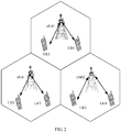
- FIG. 2 is a schematic diagram of a network architecture of an interference cancellation method according to an embodiment of this application.
- a plurality of base stations (an eNB1, an eNB2, and an eNB3) and a plurality of user equipments (UE1 to UE6) are included.
- the network architecture shown in FIG. 2 divides a network service area into cells of regular hexagons. A base station is deployed in each cell, and the base station provides network coverage for user equipments in the cells.
- the regular hexagon under each base station represents a network coverage area of the current base station, and a cellular network structure is formed.
- User equipment 1 (UE1) and user equipment 2 (UE2) are in a network coverage area of the eNB1.
- the eNB2 and the eNB3 are base stations in a neighboring cell of the cell in which the eNB1 is currently located.
- a first base station obtains system information of a neighboring cell, where the first base station is any base station in the network architecture shown in FIG. 2 .
- the first base station determines interference channel information between a second base station and the first base station based on the system information, where the second base station is a base station in a coverage area of the neighboring cell.
- the first base station sends a downlink signal to user equipment in a coverage area of the first base station based on the interference channel information. For example, when the eNB1 needs to send a downlink signal to the UE1, the eNB1 first obtains system information of a neighboring cell of the eNB1, then determines interference channel information between the eNB1 and the eNB2 and interference channel information between the eNB1 and the eNB2 based on the obtained system information, and finally sends the downlink signal to the UE1 based on the obtained interference channel information.
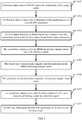
- FIG. 3 is a schematic flowchart of an embodiment of the embodiments of this application, including the following steps.
- a first base station obtains PCI information of a neighboring cell by using a sniffer.
- the PCI information of the neighboring cell is a physical cell identifier of the neighboring cell, and is used to distinguish radio signals in different cells, so as to ensure that there is no duplicate physical cell identifier in coverage areas of the related cells.
- Each cell has only one physical cell identifier.
- cell ID grouping is used in an LTE cell search process. A cell group ID is first determined by using a secondary synchronization channel (English full name: Secondary Synchronization Channel, SSCH for short), and then a specific cell ID is determined by using a primary synchronization channel (English full name: Primary Synchronization Channel, PSCH for short).
- the sniffer also known as a data packet capturing tool, is a network analysis means based on a passive snooping principle. This technical means may be used to monitor a status of and data flows in a network, as well as information transmitted over the network.
- the first base station obtains the PCI information of the neighboring cell by using the sniffer, and the neighboring cell is a cell neighboring to the cell in which the first base station is located.
- the first base station obtains system information of the neighboring cell by using the PCI information.
- the first base station may obtain the system information of the neighboring cell by using the obtained PCI information.
- the first base station may obtain a synchronization sequence and a CRS pilot sequence of the neighboring cell by using the PCI information.
- the first base station determines a MIMO interference channel matrix of a second base station to the first base station based on the system information.
- the first base station may determine interference channel information of the second base station to the second base station based on the system information.
- the MIMO interference channel matrix of the second base station to the first base station may be determined based on the system information.
- the second base station is a base station in a neighboring cell of the cell in which the first base station is located.
- an eNB1 acts as the first base station in this embodiment of this application is used as an example.
- PCI information of a neighboring cell in which an eNB2 is located is obtained by using a sniffer.
- System information of the neighboring cell is obtained based on the PCI information, including a synchronization sequence and a CRS pilot sequence of the neighboring cell.
- estimation is performed at a corresponding location of a radio signal frame to measure an interference signal power and an interference channel of the neighboring cell.
- the eNB1 may estimate an interference channel H eNB2 ⁇ eNB1 of the eNB2 to the eNB1 based on the obtained system information.
- the base stations are multi-antenna base stations, the MIMO interference channel of the eNB2 to the eNB1 is estimated.
- the MIMO interference channel may be estimated within a preset period, for example, 500 ms or a longer or shorter period. A specific period range is not limited herein.
- the first base station feeds the MIMO interference channel information back to the corresponding second base station in the neighboring cell by using X2 or other approaches.
- the eNB1 feeds the MIMO interference channel of the eNB2 to the eNB1 back to the eNB2.
- FIG. 4 is only an example for description herein, and does not constitute a limitation on this embodiment of this application.
- H eNB 1 C H eNB 1 ⁇ eNB 2 T , H eNB 1 ⁇ eNB 3 T , ... , H eNB 1 ⁇ eNBK T .
- the second base station receives the MIMO interference channel matrix sent by the first base station.
- the first base station feeds the MIMO interference channel information back to the corresponding second base station in the neighboring cell by using X2 or other approaches.
- the second base station may receive the MIMO interference channel matrix fed back by the first base station.
- the second base station performs singular value decomposition on the MIMO interference channel matrix.
- H eNB 1 C U H ⁇ H V H .
- H C eNB1 is the MIMO interference channel matrix of the second base station to the first base station
- U H and V H are singular vectors corresponding to H C eNB1
- H C eNB1 is an m ⁇ n matrix
- U H is an m ⁇ m matrix corresponding to H C eNB1
- V H is an n ⁇ n matrix corresponding to H C eNB1 .
- a specific singular value decomposition process on the matrix is not described herein.
- the second base station determines a quantity y of non-zero singular values of ⁇ H .
- the second base station uses a vector behind a column y+1 of V H as a transmit null forming weight for a downlink signal.
- the second base station sends the downlink signal based on the transmit null forming weight.
- the second base station After the transmit weight W 1 is obtained, when the second base station needs to send a downlink signal to user equipment in the coverage area of the first base station, a null forming (null forming) manner is used.
- the second base station sends the downlink signal to the user equipment in the coverage area of the first base station based on the calculated transmit null forming weight W 1 .
- FIG. 4 is still used as an example. It should be understood that, the vectors behind the column y+1 of V H are vectors in null space, and therefore these vectors are orthogonal to H eNB 1 C . When the eNB1 performs weighting by using these vectors, the eNB2 cannot receive signals weighted by using these vectors. For example, a downlink transmit signal is x , and a vector W 1 behind the column y+1 is selected to transmit the signal to the UE2. Therefore, a weighted transmit vector is W 1 x and a signal received by the UE2 is H eNB1 ⁇ UE2 w 1 x . H eNB1 ⁇ UE2 represents a channel from the eNB1 to the UE2.
- IRC interference rejection combining
- a base station not only uses transmit weighing to reduce interference between base stations, but also considers interference from other cells in a reception process of the base station.
- every base station uses an IRC receiver and obtains the interference autocorrelation matrix by using the IRC receiver.
- the interference between the eNBs is further suppressed by using the IRC receiver, to reduce the interference between the eNBs.
- the first base station obtains the system information of the neighboring cell; determines the interference channel information of the second base station to the first base station based on the system information, where the second base station is a base station in the coverage area of the neighboring cell; and receives, based on the interference channel information, the uplink signal sent by the user equipment in the coverage area of the first base station.
- the first base station estimates an interference channel of the second base station in the neighboring cell to the first base station and obtains interference channel information. Therefore, when the first base station receives an uplink signal sent by user equipment, interference impact from base stations in other cells can be comprehensively considered. This can effectively reduce interference between cells in a co-time co-frequency full-duplex communications system.
- FIG. 5 is a schematic diagram of an embodiment of the base station in the embodiments of this application.
- the base station includes an obtaining module 101, a processing module 102, a receiving module 103, and a sending module 104.
- the obtaining module 101 is configured to obtain system information of a neighboring cell.
- the processing module 102 is configured to determine interference channel information of a second base station to the first base station based on the system information obtained by the obtaining module 101, where the second base station is a base station in a coverage area of the neighboring cell.
- the receiving module 103 is configured to receive, based on the information that is about the interference channel and is determined by the determining module, an uplink signal sent by user equipment in a coverage area of the first base station.
- the obtaining module 101 is specifically configured to:
- the processing module 102 is specifically configured to: determine a MIMO interference channel matrix of the second base station to the first base station based on the system information obtained by the obtaining module 101.
- the processing module 102 is specifically configured to: determine the MIMO interference channel matrix of the second base station to the first base station by using a synchronization sequence and a cell-specific reference signal CRS pilot sequence of the neighboring cell.
- the processing module 102 is further configured to: determine a corresponding interference autocorrelation matrix based on the MIMO interference channel matrix; and the receiving module 103 is configured to: use the interference autocorrelation matrix to receive, by using an interference rejection combining IRC receiver, the uplink signal sent by the user equipment in the coverage area of the first base station.
- the sending module 104 is configured to send the interference channel information to the second base station, so that the second base station sends a downlink signal based on the interference channel information when sending the downlink signal to user equipment in a coverage area of the second base station.
- FIG. 6 is a schematic diagram of another embodiment of the base station in the embodiments of this application.
- the base station includes a receiving module 201, a sending module 202, and a processing module 203.
- the receiving module 201 is configured to receive information that is about an interference channel to a first base station and is sent by the first base station, where the interference channel information is determined by the first base station based on system information, and the system information is system information of a cell in which the second base station is located.
- the sending module 202 is configured to send a downlink signal to user equipment in a coverage area of the second base station based on the interference channel information.
- the sending module 202 is specifically configured to: send, based on the interference channel information, the downlink signal to the user equipment in the coverage area of the second base station in a null forming manner, where a null forming direction of a transmit beam used by the second base station to send the downlink signal is aligned with the first base station.
- the interference channel information is a MIMO interference channel matrix of the second base station to the first base station.
- the sending module 202 is specifically configured to: send the downlink signal to the user equipment in the coverage area of the second base station based on the transmit null forming weight.
- the first base station obtains the system information of the neighboring cell; determines the interference channel information of the second base station to the first base station based on the system information, where the second base station is a base station in the coverage area of the neighboring cell; and receives, based on the interference channel information, the uplink signal sent by the user equipment in the coverage area of the first base station.
- the first base station estimates an interference channel of the second base station in the neighboring cell to the first base station and obtains interference channel information. Therefore, when the first base station receives an uplink signal sent by user equipment, interference impact from base stations in other cells can be comprehensively considered. This can effectively reduce interference between cells in a co-time co-frequency full-duplex communications system.
- FIG. 7 is a schematic structural diagram of an embodiment of a base station in the embodiments of this application.
- the base station 300 includes a processor 301, a memory 302, and a communications interface 303.
- the processor 301, the memory 302, and the communications interface 303 are connected to each other through a bus 304.
- the processor 301 may be a central processing unit (English full name: central processing unit, CPU for short), a network processor (English full name: network processor, NP for short), or a combination of a CPU and an NP.
- the processor may further include a hardware chip, which may be specifically an application-specific integrated circuit (English full name: application-specific integrated circuit, ASIC for short), a programmable logic device (English full name: programmable logic device, PLD for short), or a combination thereof.
- the PLD may be a complex programmable logic device (English full name: complex programmable logic device, CPLD for short), a field-programmable gate array (English full name: field-programmable gate array, FPGA for short), a generic array logic (English full name: generic array logic, GAL for short), or any combination of thereof. No limitation is imposed thereon in this application.
- the memory 302 may include a volatile memory (English full name: volatile memory), for example, a random access memory (English full name: random-access memory, RAM for short); or the memory may include a non-volatile memory (English full name: non-volatile memory), for example, a flash memory (English full name: flash memory), a hard disk drive (English full name: hard disk drive, HDD for short) or a solid-state drive (English full name: solid-state drive, SSD for short); or the memory may include a combination of the foregoing types of memories.
- the bus 304 may be a Peripheral Component Interconnect (English full name: peripheral component interconnect, PCI for short) bus, an Extended Industry Standard Architecture (English full name: extended industry standard architecture, EISA for short) bus, or the like.
- the bus may be further classified into an address bus, a data bus, a control bus, and the like. For ease of representation, only one thick line is used in FIG. 7 to represent the bus, but this does not mean that there is only one bus or only one type of bus.
- the communications interface 303 is configured to send or receive an instruction or information used by the base station in the foregoing method embodiments, for example, interference channel information and system information of a neighboring cell.
- the memory 302 may store program code 305, and may further store data 306 used by the first base station or the second base station in the foregoing method embodiments.
- the data 306 may be interference channel information and system information of a neighboring cell.
- the processor 301 may invoke the program code 305 stored in the memory to implement the steps corresponding to the first base station or the second base station in the foregoing method embodiments, so that the base station can ultimately implement actions or functions of the first base station or the second base station in the foregoing method embodiments.
- the base station 300 may further include a power supply 307.
- system structure of the base station shown in FIG. 7 does not constitute a limitation on the base station structure in this embodiment of this application.
- the system structure of the base station may include components more or fewer than those shown in the figure, or combine some components, or have different arrangements of components. Details are not described herein again.
- the steps implemented by a base station in the embodiments of this application may be based on the schematic structural diagram of the authentication server system shown in FIG. 7 .
- the steps implemented by a base station in the embodiments of this application may be based on the schematic structural diagram of the authentication server system shown in FIG. 7 .
- the disclosed system, module, and method may be implemented in other manners.
- the described apparatus embodiments are merely examples.
- the module division is merely division by logical function and may be other division in actual implementation.
- a plurality of units or components may be combined or integrated into another system, or some features may be ignored or may not be performed.
- the displayed or discussed mutual couplings or direct couplings or communication connections may be indirect couplings or communication connections through some interfaces, apparatuses or units, and may be implemented in electronic, mechanical, or other forms.
- the units described as separate parts may or may not be physically separate. Part displayed as units may or may not be physical units, and may be located in one position or distributed on a plurality of network units. Some or all of the units may be selected based on actual requirements to achieve the objectives of the solutions of the embodiments.
- functional units in the embodiments of this application may be integrated into one processing unit, or each of the units may exist alone physically, or two or more units are integrated into one unit.
- the integrated unit may be implemented in a form of hardware, or may be implemented in a form of a software functional unit.
- the integrated unit When the integrated unit is implemented in the form of a software functional unit and sold or used as an independent product, the integrated unit may be stored in a computer readable storage medium. Based on such an understanding, the technical solutions of this application essentially, or the part contributing to the prior art, or all or some of the technical solutions may be implemented in the form of a software product.
- the software product is stored in a storage medium and includes several instructions for instructing a computer device (which may be a personal computer, a server, or a network device) to perform all or some of the steps of the methods described in the embodiments of this application.
- the foregoing storage medium includes any medium that can store program code, such as a USB flash drive, a portable hard disk, a read-only memory (English full name: Read-Only Memory, ROM for short), a random access memory (English full name: Random Access Memory, RAM for short), a magnetic disk, or an optical disc.
- program code such as a USB flash drive, a portable hard disk, a read-only memory (English full name: Read-Only Memory, ROM for short), a random access memory (English full name: Random Access Memory, RAM for short), a magnetic disk, or an optical disc.
Landscapes
- Engineering & Computer Science (AREA)
- Signal Processing (AREA)
- Computer Networks & Wireless Communication (AREA)
- Physics & Mathematics (AREA)
- Mathematical Physics (AREA)
- Mobile Radio Communication Systems (AREA)
Applications Claiming Priority (2)
| Application Number | Priority Date | Filing Date | Title |
|---|---|---|---|
| CN201611249134.2A CN107070581B (zh) | 2016-12-29 | 2016-12-29 | 一种干扰消除方法以及基站 |
| PCT/CN2017/118185 WO2018121461A1 (fr) | 2016-12-29 | 2017-12-25 | Procédé d'élimination d'interférence, et station de base |
Publications (3)
| Publication Number | Publication Date |
|---|---|
| EP3540988A1 true EP3540988A1 (fr) | 2019-09-18 |
| EP3540988A4 EP3540988A4 (fr) | 2019-12-25 |
| EP3540988B1 EP3540988B1 (fr) | 2023-10-04 |
Family
ID=59623574
Family Applications (1)
| Application Number | Title | Priority Date | Filing Date |
|---|---|---|---|
| EP17887453.3A Active EP3540988B1 (fr) | 2016-12-29 | 2017-12-25 | Procédé d'élimination d'interférence, et station de base |
Country Status (7)
| Country | Link |
|---|---|
| US (1) | US11057138B2 (fr) |
| EP (1) | EP3540988B1 (fr) |
| JP (1) | JP7010501B2 (fr) |
| KR (1) | KR102285020B1 (fr) |
| CN (1) | CN107070581B (fr) |
| RU (1) | RU2752004C2 (fr) |
| WO (1) | WO2018121461A1 (fr) |
Cited By (1)
| Publication number | Priority date | Publication date | Assignee | Title |
|---|---|---|---|---|
| WO2022242820A1 (fr) * | 2021-05-17 | 2022-11-24 | Telefonaktiebolaget Lm Ericsson (Publ) | Atténuation d'interférence d'une communication en duplex intégral |
Families Citing this family (7)
| Publication number | Priority date | Publication date | Assignee | Title |
|---|---|---|---|---|
| CN107070581B (zh) | 2016-12-29 | 2019-10-25 | 上海华为技术有限公司 | 一种干扰消除方法以及基站 |
| CN107682034A (zh) * | 2017-11-21 | 2018-02-09 | 桂林爱家购股份有限公司 | 一种通信基站及方法 |
| WO2020024081A1 (fr) | 2018-07-28 | 2020-02-06 | Qualcomm Incorporated | Signal de référence de gestion d'interférence à distance |
| CN111836287A (zh) | 2019-04-19 | 2020-10-27 | 索尼公司 | 用于无线通信系统的电子设备、方法和存储介质 |
| US10999102B1 (en) * | 2020-02-28 | 2021-05-04 | Nxp B.V. | FM spectrum estimation relative to adjacent channel |
| CN111245454B (zh) * | 2020-04-26 | 2020-09-08 | 北京全路通信信号研究设计院集团有限公司 | 一种抗同频干扰信号的通信方法和系统 |
| CN115484610B (zh) * | 2021-06-16 | 2026-03-10 | 深圳市运联通通信服务有限公司 | 专网通信的干扰消除方法、装置、基站及通信系统 |
Family Cites Families (65)
| Publication number | Priority date | Publication date | Assignee | Title |
|---|---|---|---|---|
| US5680395A (en) * | 1995-08-15 | 1997-10-21 | Qualcomm Incorporated | Method and apparatus for time division duplex pilot signal generation |
| US7200183B2 (en) * | 2001-11-16 | 2007-04-03 | Tensorcomm Inc. | Construction of an interference matrix for a coded signal processing engine |
| DE10315629A1 (de) * | 2003-04-04 | 2004-10-14 | T-Mobile Deutschland Gmbh | Verfahren zur Analyse der Interferenz- und Versorgungssituation in UMTS-Teilnetzen |
| US7339980B2 (en) * | 2004-03-05 | 2008-03-04 | Telefonaktiebolaget Lm Ericsson (Publ) | Successive interference cancellation in a generalized RAKE receiver architecture |
| US8000420B2 (en) * | 2005-06-24 | 2011-08-16 | Telefonaktiebolaget L M Ericsson (Publ) | System and method of joint synchronization and noise covariance estimation |
| CN101375567B (zh) * | 2006-03-16 | 2013-01-23 | 英特尔公司 | 采用递归滤波的信道估计方法和具有干扰感知解调的多载波接收器 |
| US8059739B2 (en) * | 2006-06-05 | 2011-11-15 | Telefonaktiebolaget Lm Ericsson | Method and apparatus for correcting data transmission errors |
| KR100951382B1 (ko) * | 2006-09-07 | 2010-04-08 | 삼성전자주식회사 | 시분할 복신 시스템에서 상향링크 수신신호의 간섭 제거방법 및 장치 |
| US8229050B2 (en) * | 2007-05-28 | 2012-07-24 | Telefonaktiebolaget Lm Ericsson (Publ) | Method and arrangement for improved model order selection |
| KR100991792B1 (ko) * | 2007-12-31 | 2010-11-04 | 엘지전자 주식회사 | 협력적 다중 입출력 방식 신호 송수신 방법 |
| KR101481045B1 (ko) * | 2008-04-17 | 2015-01-09 | 삼성전자주식회사 | 광대역 무선통신 시스템에서 간섭의 크기를 고려한 빔포밍장치 및 방법 |
| JP5121754B2 (ja) | 2009-02-25 | 2013-01-16 | 日本電信電話株式会社 | 無線通信方法、受信用基地局、及び中継局 |
| US9312978B2 (en) * | 2009-03-04 | 2016-04-12 | Centre Of Excellence In Wireless Technology | Pilot aided data transmission and reception with interference mitigation in wireless systems |
| US9402193B2 (en) * | 2009-03-19 | 2016-07-26 | Qualcomm Incorporated | Systems, apparatus and methods for interference management in wireless networks |
| CN101841903A (zh) | 2009-03-20 | 2010-09-22 | 松下电器产业株式会社 | 无线通信系统中减小基站间干扰的装置和方法 |
| US9491648B2 (en) * | 2009-07-21 | 2016-11-08 | Lg Electronics Inc. | Apparatus and method for transmitting channel state information in a wireless communication system |
| KR101728544B1 (ko) * | 2010-01-22 | 2017-04-19 | 삼성전자주식회사 | 다중 입력 다중 출력 통신 시스템에서의 스케줄링 방법 및 장치 |
| CN102457319B (zh) * | 2010-10-28 | 2014-04-09 | 中兴通讯股份有限公司 | 业务数据下发方法和装置 |
| US8687727B2 (en) * | 2010-11-05 | 2014-04-01 | Intel Corporation | Coordinated multi-point transmission using interference feedback |
| US8675558B2 (en) * | 2011-01-07 | 2014-03-18 | Intel Corporation | CQI definition for transmission mode 9 in LTE-advanced |
| JP5780316B2 (ja) * | 2011-03-10 | 2015-09-16 | 富士通株式会社 | 干渉協調方法、基地局及びユーザー機器 |
| US8644330B2 (en) * | 2011-03-29 | 2014-02-04 | Intel Corporation | Architecture and method of channel estimation for wireless communication system |
| CN102149130B (zh) * | 2011-04-22 | 2014-01-01 | 电信科学技术研究院 | 一种信道质量指示的上报方法、装置及系统 |
| US8855000B2 (en) * | 2011-04-28 | 2014-10-07 | Qualcomm Incorporated | Interference estimation using data traffic power and reference signal power |
| CN105792277B (zh) * | 2011-09-26 | 2019-06-28 | 华为技术有限公司 | 干扰控制方法和设备 |
| WO2013059451A1 (fr) * | 2011-10-19 | 2013-04-25 | Marvell World Trade Ltd | Systèmes et procédés pour supprimer un brouillage à partir d'un signal reçu au moyen d'un dispositif comprenant deux antennes ou plus |
| US9473279B2 (en) * | 2011-11-04 | 2016-10-18 | Blackberry Limited | Inter-cell interference coordination for E-PDCCH |
| EP2597793A1 (fr) * | 2011-11-25 | 2013-05-29 | TELEFONAKTIEBOLAGET LM ERICSSON (publ) | Procédé pour estimer l'interférence dans une cellule de serveur, équipement utilisateur, programme informatique et produits de programme informatique |
| CN103138822B (zh) * | 2011-12-05 | 2017-04-12 | 华为技术有限公司 | 传输信号的方法和设备 |
| CN104115460A (zh) * | 2012-01-30 | 2014-10-22 | 美国博通公司 | 用于提供增强干扰抑制的方法和设备 |
| JP2013251860A (ja) * | 2012-06-04 | 2013-12-12 | Ntt Docomo Inc | 通信制御方法、無線通信システム、無線基地局及びユーザ端末 |
| US9392477B2 (en) * | 2012-06-14 | 2016-07-12 | Nokia Solutions And Networks Oy | Neighbor cell interference estimation |
| WO2014000213A1 (fr) * | 2012-06-28 | 2014-01-03 | Renesas Mobile Corporation | Appareils, procédés et produits programme d'ordinateur associés à des améliorations apportées à des scénarios de suppression d'interférences |
| JP5935583B2 (ja) | 2012-08-07 | 2016-06-15 | 富士通株式会社 | 小規模基地局、通信システムおよび通信方法 |
| CN102916735B (zh) * | 2012-10-17 | 2016-06-08 | 东南大学 | 利用大规模天线阵列的无线通信方法 |
| US9420476B2 (en) * | 2013-02-20 | 2016-08-16 | Telefonaktiebolaget L M Ericsson (Publ) | Systems and methods of triggering interference mitigation without resource partitioning |
| WO2014166061A1 (fr) * | 2013-04-09 | 2014-10-16 | Qualcomm Incorporated | Réalisation de mesures enb-enb et ue-ue pour atténuer le brouillage |
| JP6151074B2 (ja) * | 2013-04-15 | 2017-06-21 | 京セラ株式会社 | 通信システムおよび通信制御方法 |
| US9571242B2 (en) * | 2013-04-26 | 2017-02-14 | Intel Deutschland Gmbh | Methods and devices for mitigating interference |
| KR102138123B1 (ko) * | 2013-06-13 | 2020-07-27 | 삼성전자 주식회사 | 무선 통신 시스템에서 간섭 제어 방법 및 장치 |
| EP3011693B1 (fr) * | 2013-06-19 | 2019-08-07 | LG Electronics Inc. | Procédé d'annulation de brouillage dans un système de communication sans fil et appareil pour celui-ci |
| US9461757B2 (en) * | 2013-06-26 | 2016-10-04 | Intel IP Corporation | Method and device for processing a signal based on a first and a second covariance measure |
| US9294214B2 (en) | 2013-08-05 | 2016-03-22 | Huawei Technologies Co., Ltd. | Coordinated multipoint (COMP) techniques for reducing downlink interference from uplink signals |
| DE102013110833B4 (de) * | 2013-09-30 | 2018-10-18 | Intel IP Corporation | Verfahren und Vorrichtungen zum Bestimmen von effektiven gegenseitigen Informationen |
| WO2015054201A2 (fr) * | 2013-10-07 | 2015-04-16 | Nokia Solutions And Networks Oy | Définition de ressources d'estimation d'interférence et son utilisation pour des récepteurs améliorés |
| JP6213137B2 (ja) * | 2013-10-17 | 2017-10-18 | 富士通株式会社 | 移動局、及び受信品質測定方法 |
| CN104735789B (zh) * | 2013-12-19 | 2018-06-26 | 中国移动通信集团公司 | 一种小区间干扰消除方法、装置及系统 |
| US9813216B2 (en) * | 2014-04-04 | 2017-11-07 | Lg Electronics Inc. | Method for reporting channel state information having interference cancellation capability reflected therein, and apparatus therefor |
| CN104980380A (zh) | 2014-04-14 | 2015-10-14 | 株式会社Ntt都科摩 | 基站、通信系统及其方法 |
| KR102244366B1 (ko) * | 2014-05-09 | 2021-04-26 | 삼성전자주식회사 | 무선통신 시스템에서 간섭 신호 제거 및 억제를 위한 무선 자원 활용 방법 및 장치 |
| US20150334743A1 (en) * | 2014-05-15 | 2015-11-19 | Qualcomm Incorporated | Physical cell identifier and physical random access channel offset joint planning |
| WO2016018079A1 (fr) * | 2014-08-01 | 2016-02-04 | 엘지전자 주식회사 | Procédé de réception de signaux en liaison descendante et équipement d'utilisateur, et procédé d'émission de signaux en liaison descendante et station de base |
| EP3185629B1 (fr) * | 2014-08-20 | 2019-08-07 | Huawei Technologies Co., Ltd. | Dispositif, procédé de communication sans fil et station de base |
| WO2016072533A1 (fr) | 2014-11-04 | 2016-05-12 | 엘지전자 주식회사 | Procédé et appareil pour recevoir un signal dans un système d'accès sans fil prenant en charge une transmission radio duplex (fdr) |
| JPWO2016121251A1 (ja) * | 2015-01-29 | 2017-11-09 | ソニー株式会社 | 装置及び方法 |
| US10470179B2 (en) * | 2015-02-23 | 2019-11-05 | Agency For Science, Technology And Research | Radio communication methods and radio communication devices |
| US9503166B2 (en) * | 2015-03-17 | 2016-11-22 | Futurewei Technologies, Inc. | System and method for coordinated MIMO switching (CMS) in TDD/FDD-LTE |
| US9894528B2 (en) * | 2015-08-14 | 2018-02-13 | Avago Technologies General Ip (Singapore) Pte. Ltd. | Methods and systems for almost blank subframe (ABS) pattern selection for small cells |
| CN105007248B (zh) * | 2015-08-25 | 2018-05-18 | 成都东讯电子技术有限公司 | 一种mimo全双工蜂窝系统的下行预编码方法 |
| WO2017043878A1 (fr) * | 2015-09-08 | 2017-03-16 | 엘지전자 주식회사 | Procédé et appareil pour recevoir un canal physique de diffusion de liaison descendante dans un système d'accès radio qui prend en charge un internet des objets à bande étroite |
| US10374836B2 (en) * | 2015-10-28 | 2019-08-06 | Huawei Technologies Canada Co., Ltd. | Method and apparatus for downlink channel estimation in massive MIMO |
| EP3391601B8 (fr) * | 2015-12-18 | 2021-01-20 | Apple Inc. | Terminal de communication et procédé d'estimation de canal |
| US9853667B2 (en) * | 2016-05-25 | 2017-12-26 | Apple Inc. | Noise and interference estimation for colliding neighbor reference signals |
| US10541850B2 (en) * | 2016-10-31 | 2020-01-21 | Southeast University | Systems and methods for wireless communication with per-beam signal synchronization |
| CN107070581B (zh) * | 2016-12-29 | 2019-10-25 | 上海华为技术有限公司 | 一种干扰消除方法以及基站 |
-
2016
- 2016-12-29 CN CN201611249134.2A patent/CN107070581B/zh active Active
-
2017
- 2017-12-25 JP JP2019530205A patent/JP7010501B2/ja active Active
- 2017-12-25 EP EP17887453.3A patent/EP3540988B1/fr active Active
- 2017-12-25 WO PCT/CN2017/118185 patent/WO2018121461A1/fr not_active Ceased
- 2017-12-25 RU RU2019123285A patent/RU2752004C2/ru active
- 2017-12-25 KR KR1020197019167A patent/KR102285020B1/ko active Active
-
2019
- 2019-06-26 US US16/453,830 patent/US11057138B2/en active Active
Cited By (1)
| Publication number | Priority date | Publication date | Assignee | Title |
|---|---|---|---|---|
| WO2022242820A1 (fr) * | 2021-05-17 | 2022-11-24 | Telefonaktiebolaget Lm Ericsson (Publ) | Atténuation d'interférence d'une communication en duplex intégral |
Also Published As
| Publication number | Publication date |
|---|---|
| JP2020511802A (ja) | 2020-04-16 |
| CN107070581A (zh) | 2017-08-18 |
| KR20190086570A (ko) | 2019-07-22 |
| CN107070581B (zh) | 2019-10-25 |
| KR102285020B1 (ko) | 2021-08-02 |
| US20190319731A1 (en) | 2019-10-17 |
| EP3540988A4 (fr) | 2019-12-25 |
| JP7010501B2 (ja) | 2022-01-26 |
| US11057138B2 (en) | 2021-07-06 |
| EP3540988B1 (fr) | 2023-10-04 |
| RU2752004C2 (ru) | 2021-07-21 |
| WO2018121461A1 (fr) | 2018-07-05 |
| RU2019123285A3 (fr) | 2021-02-09 |
| RU2019123285A (ru) | 2021-01-29 |
Similar Documents
| Publication | Publication Date | Title |
|---|---|---|
| US11057138B2 (en) | Interference cancellation method and base station | |
| CN110521135B (zh) | 用于通信波束恢复的系统和方法 | |
| JP6680384B2 (ja) | 通信装置、方法、及びプログラム | |
| EP2793523B1 (fr) | Appareil et procédé de traitement d'interférence en duplex intégral | |
| EP3737022B1 (fr) | Procédé, dispositif et équipement de détermination d'informations de quasi-colocalisation | |
| US10250312B2 (en) | Methods and systems for multi-user beamforming | |
| TWI713448B (zh) | 通訊控制裝置 | |
| US20120122502A1 (en) | Method and apparatus of controlling inter cell interference based on cooperation of intra cell terminals | |
| EP3038423B1 (fr) | Système d'antenne et procédé de traitement | |
| WO2016189990A1 (fr) | Dispositif de communication sans fil, dispositif de terminal et procédé | |
| US9654987B2 (en) | Interference alignment method and apparatus in wireless communication system | |
| US10455591B2 (en) | Apparatuses, methods, computer programs, and computer program products for interference avoidance | |
| US20220190995A1 (en) | Electronic device, method, and storage medium for wireless communication system | |
| WO2017077753A1 (fr) | Dispositif et procédé | |
| US20140314011A1 (en) | Method and base station for transmitting signal | |
| EP3518430B1 (fr) | Procédé et dispositif d'attribution de port d'antenne | |
| KR102474104B1 (ko) | 통신 디바이스로부터의 빔 보고 | |
| EP3337232B1 (fr) | Procédé et appareil pour déterminer une ressource de transmission multipoint | |
| EP3429094B1 (fr) | Station de base | |
| Khlass et al. | Analytical modeling of downlink CoMP in LTE-advanced | |
| KR20140074723A (ko) | 다중 셀 환경에서 피드백을 통한 채널 상태 정보 공유 방법 | |
| KR20120071115A (ko) | 셀룰러 시스템에서 인접 셀간 간섭 제어 방법 | |
| WO2016121200A1 (fr) | Dispositif |
Legal Events
| Date | Code | Title | Description |
|---|---|---|---|
| STAA | Information on the status of an ep patent application or granted ep patent |
Free format text: STATUS: THE INTERNATIONAL PUBLICATION HAS BEEN MADE |
|
| PUAI | Public reference made under article 153(3) epc to a published international application that has entered the european phase |
Free format text: ORIGINAL CODE: 0009012 |
|
| STAA | Information on the status of an ep patent application or granted ep patent |
Free format text: STATUS: REQUEST FOR EXAMINATION WAS MADE |
|
| 17P | Request for examination filed |
Effective date: 20190614 |
|
| AK | Designated contracting states |
Kind code of ref document: A1 Designated state(s): AL AT BE BG CH CY CZ DE DK EE ES FI FR GB GR HR HU IE IS IT LI LT LU LV MC MK MT NL NO PL PT RO RS SE SI SK SM TR |
|
| AX | Request for extension of the european patent |
Extension state: BA ME |
|
| A4 | Supplementary search report drawn up and despatched |
Effective date: 20191121 |
|
| RIC1 | Information provided on ipc code assigned before grant |
Ipc: H04J 11/00 20060101AFI20191115BHEP |
|
| DAV | Request for validation of the european patent (deleted) | ||
| DAX | Request for extension of the european patent (deleted) | ||
| STAA | Information on the status of an ep patent application or granted ep patent |
Free format text: STATUS: EXAMINATION IS IN PROGRESS |
|
| 17Q | First examination report despatched |
Effective date: 20211004 |
|
| GRAP | Despatch of communication of intention to grant a patent |
Free format text: ORIGINAL CODE: EPIDOSNIGR1 |
|
| STAA | Information on the status of an ep patent application or granted ep patent |
Free format text: STATUS: GRANT OF PATENT IS INTENDED |
|
| RIC1 | Information provided on ipc code assigned before grant |
Ipc: H04L 27/26 20060101ALI20230331BHEP Ipc: H04L 5/14 20060101ALI20230331BHEP Ipc: H04L 5/00 20060101ALI20230331BHEP Ipc: H04B 7/0413 20170101ALI20230331BHEP Ipc: H04B 7/024 20170101ALI20230331BHEP Ipc: H04J 11/00 20060101AFI20230331BHEP |
|
| INTG | Intention to grant announced |
Effective date: 20230509 |
|
| GRAS | Grant fee paid |
Free format text: ORIGINAL CODE: EPIDOSNIGR3 |
|
| GRAA | (expected) grant |
Free format text: ORIGINAL CODE: 0009210 |
|
| STAA | Information on the status of an ep patent application or granted ep patent |
Free format text: STATUS: THE PATENT HAS BEEN GRANTED |
|
| AK | Designated contracting states |
Kind code of ref document: B1 Designated state(s): AL AT BE BG CH CY CZ DE DK EE ES FI FR GB GR HR HU IE IS IT LI LT LU LV MC MK MT NL NO PL PT RO RS SE SI SK SM TR |
|
| REG | Reference to a national code |
Ref country code: GB Ref legal event code: FG4D |
|
| REG | Reference to a national code |
Ref country code: CH Ref legal event code: EP |
|
| REG | Reference to a national code |
Ref country code: IE Ref legal event code: FG4D |
|
| REG | Reference to a national code |
Ref country code: DE Ref legal event code: R096 Ref document number: 602017075057 Country of ref document: DE |
|
| REG | Reference to a national code |
Ref country code: LT Ref legal event code: MG9D |
|
| REG | Reference to a national code |
Ref country code: NL Ref legal event code: MP Effective date: 20231004 |
|
| REG | Reference to a national code |
Ref country code: AT Ref legal event code: MK05 Ref document number: 1618862 Country of ref document: AT Kind code of ref document: T Effective date: 20231004 |
|
| PG25 | Lapsed in a contracting state [announced via postgrant information from national office to epo] |
Ref country code: NL Free format text: LAPSE BECAUSE OF FAILURE TO SUBMIT A TRANSLATION OF THE DESCRIPTION OR TO PAY THE FEE WITHIN THE PRESCRIBED TIME-LIMIT Effective date: 20231004 |
|
| PG25 | Lapsed in a contracting state [announced via postgrant information from national office to epo] |
Ref country code: GR Free format text: LAPSE BECAUSE OF FAILURE TO SUBMIT A TRANSLATION OF THE DESCRIPTION OR TO PAY THE FEE WITHIN THE PRESCRIBED TIME-LIMIT Effective date: 20240105 |
|
| PG25 | Lapsed in a contracting state [announced via postgrant information from national office to epo] |
Ref country code: IS Free format text: LAPSE BECAUSE OF FAILURE TO SUBMIT A TRANSLATION OF THE DESCRIPTION OR TO PAY THE FEE WITHIN THE PRESCRIBED TIME-LIMIT Effective date: 20240204 |
|
| PG25 | Lapsed in a contracting state [announced via postgrant information from national office to epo] |
Ref country code: LT Free format text: LAPSE BECAUSE OF FAILURE TO SUBMIT A TRANSLATION OF THE DESCRIPTION OR TO PAY THE FEE WITHIN THE PRESCRIBED TIME-LIMIT Effective date: 20231004 |
|
| PG25 | Lapsed in a contracting state [announced via postgrant information from national office to epo] |
Ref country code: AT Free format text: LAPSE BECAUSE OF FAILURE TO SUBMIT A TRANSLATION OF THE DESCRIPTION OR TO PAY THE FEE WITHIN THE PRESCRIBED TIME-LIMIT Effective date: 20231004 |
|
| PG25 | Lapsed in a contracting state [announced via postgrant information from national office to epo] |
Ref country code: ES Free format text: LAPSE BECAUSE OF FAILURE TO SUBMIT A TRANSLATION OF THE DESCRIPTION OR TO PAY THE FEE WITHIN THE PRESCRIBED TIME-LIMIT Effective date: 20231004 |
|
| PG25 | Lapsed in a contracting state [announced via postgrant information from national office to epo] |
Ref country code: LT Free format text: LAPSE BECAUSE OF FAILURE TO SUBMIT A TRANSLATION OF THE DESCRIPTION OR TO PAY THE FEE WITHIN THE PRESCRIBED TIME-LIMIT Effective date: 20231004 Ref country code: IS Free format text: LAPSE BECAUSE OF FAILURE TO SUBMIT A TRANSLATION OF THE DESCRIPTION OR TO PAY THE FEE WITHIN THE PRESCRIBED TIME-LIMIT Effective date: 20240204 Ref country code: GR Free format text: LAPSE BECAUSE OF FAILURE TO SUBMIT A TRANSLATION OF THE DESCRIPTION OR TO PAY THE FEE WITHIN THE PRESCRIBED TIME-LIMIT Effective date: 20240105 Ref country code: ES Free format text: LAPSE BECAUSE OF FAILURE TO SUBMIT A TRANSLATION OF THE DESCRIPTION OR TO PAY THE FEE WITHIN THE PRESCRIBED TIME-LIMIT Effective date: 20231004 Ref country code: BG Free format text: LAPSE BECAUSE OF FAILURE TO SUBMIT A TRANSLATION OF THE DESCRIPTION OR TO PAY THE FEE WITHIN THE PRESCRIBED TIME-LIMIT Effective date: 20240104 Ref country code: AT Free format text: LAPSE BECAUSE OF FAILURE TO SUBMIT A TRANSLATION OF THE DESCRIPTION OR TO PAY THE FEE WITHIN THE PRESCRIBED TIME-LIMIT Effective date: 20231004 Ref country code: PT Free format text: LAPSE BECAUSE OF FAILURE TO SUBMIT A TRANSLATION OF THE DESCRIPTION OR TO PAY THE FEE WITHIN THE PRESCRIBED TIME-LIMIT Effective date: 20240205 |
|
| PG25 | Lapsed in a contracting state [announced via postgrant information from national office to epo] |
Ref country code: SE Free format text: LAPSE BECAUSE OF FAILURE TO SUBMIT A TRANSLATION OF THE DESCRIPTION OR TO PAY THE FEE WITHIN THE PRESCRIBED TIME-LIMIT Effective date: 20231004 Ref country code: RS Free format text: LAPSE BECAUSE OF FAILURE TO SUBMIT A TRANSLATION OF THE DESCRIPTION OR TO PAY THE FEE WITHIN THE PRESCRIBED TIME-LIMIT Effective date: 20231004 Ref country code: PL Free format text: LAPSE BECAUSE OF FAILURE TO SUBMIT A TRANSLATION OF THE DESCRIPTION OR TO PAY THE FEE WITHIN THE PRESCRIBED TIME-LIMIT Effective date: 20231004 Ref country code: NO Free format text: LAPSE BECAUSE OF FAILURE TO SUBMIT A TRANSLATION OF THE DESCRIPTION OR TO PAY THE FEE WITHIN THE PRESCRIBED TIME-LIMIT Effective date: 20240104 Ref country code: LV Free format text: LAPSE BECAUSE OF FAILURE TO SUBMIT A TRANSLATION OF THE DESCRIPTION OR TO PAY THE FEE WITHIN THE PRESCRIBED TIME-LIMIT Effective date: 20231004 Ref country code: HR Free format text: LAPSE BECAUSE OF FAILURE TO SUBMIT A TRANSLATION OF THE DESCRIPTION OR TO PAY THE FEE WITHIN THE PRESCRIBED TIME-LIMIT Effective date: 20231004 |
|
| REG | Reference to a national code |
Ref country code: DE Ref legal event code: R097 Ref document number: 602017075057 Country of ref document: DE |
|
| PG25 | Lapsed in a contracting state [announced via postgrant information from national office to epo] |
Ref country code: DK Free format text: LAPSE BECAUSE OF FAILURE TO SUBMIT A TRANSLATION OF THE DESCRIPTION OR TO PAY THE FEE WITHIN THE PRESCRIBED TIME-LIMIT Effective date: 20231004 |
|
| PG25 | Lapsed in a contracting state [announced via postgrant information from national office to epo] |
Ref country code: CZ Free format text: LAPSE BECAUSE OF FAILURE TO SUBMIT A TRANSLATION OF THE DESCRIPTION OR TO PAY THE FEE WITHIN THE PRESCRIBED TIME-LIMIT Effective date: 20231004 |
|
| PG25 | Lapsed in a contracting state [announced via postgrant information from national office to epo] |
Ref country code: SK Free format text: LAPSE BECAUSE OF FAILURE TO SUBMIT A TRANSLATION OF THE DESCRIPTION OR TO PAY THE FEE WITHIN THE PRESCRIBED TIME-LIMIT Effective date: 20231004 |
|
| PG25 | Lapsed in a contracting state [announced via postgrant information from national office to epo] |
Ref country code: SM Free format text: LAPSE BECAUSE OF FAILURE TO SUBMIT A TRANSLATION OF THE DESCRIPTION OR TO PAY THE FEE WITHIN THE PRESCRIBED TIME-LIMIT Effective date: 20231004 Ref country code: SK Free format text: LAPSE BECAUSE OF FAILURE TO SUBMIT A TRANSLATION OF THE DESCRIPTION OR TO PAY THE FEE WITHIN THE PRESCRIBED TIME-LIMIT Effective date: 20231004 Ref country code: RO Free format text: LAPSE BECAUSE OF FAILURE TO SUBMIT A TRANSLATION OF THE DESCRIPTION OR TO PAY THE FEE WITHIN THE PRESCRIBED TIME-LIMIT Effective date: 20231004 Ref country code: IT Free format text: LAPSE BECAUSE OF FAILURE TO SUBMIT A TRANSLATION OF THE DESCRIPTION OR TO PAY THE FEE WITHIN THE PRESCRIBED TIME-LIMIT Effective date: 20231004 Ref country code: EE Free format text: LAPSE BECAUSE OF FAILURE TO SUBMIT A TRANSLATION OF THE DESCRIPTION OR TO PAY THE FEE WITHIN THE PRESCRIBED TIME-LIMIT Effective date: 20231004 Ref country code: DK Free format text: LAPSE BECAUSE OF FAILURE TO SUBMIT A TRANSLATION OF THE DESCRIPTION OR TO PAY THE FEE WITHIN THE PRESCRIBED TIME-LIMIT Effective date: 20231004 Ref country code: CZ Free format text: LAPSE BECAUSE OF FAILURE TO SUBMIT A TRANSLATION OF THE DESCRIPTION OR TO PAY THE FEE WITHIN THE PRESCRIBED TIME-LIMIT Effective date: 20231004 |
|
| REG | Reference to a national code |
Ref country code: CH Ref legal event code: PL |
|
| PLBE | No opposition filed within time limit |
Free format text: ORIGINAL CODE: 0009261 |
|
| STAA | Information on the status of an ep patent application or granted ep patent |
Free format text: STATUS: NO OPPOSITION FILED WITHIN TIME LIMIT |
|
| PG25 | Lapsed in a contracting state [announced via postgrant information from national office to epo] |
Ref country code: LU Free format text: LAPSE BECAUSE OF NON-PAYMENT OF DUE FEES Effective date: 20231225 |
|
| PG25 | Lapsed in a contracting state [announced via postgrant information from national office to epo] |
Ref country code: MC Free format text: LAPSE BECAUSE OF FAILURE TO SUBMIT A TRANSLATION OF THE DESCRIPTION OR TO PAY THE FEE WITHIN THE PRESCRIBED TIME-LIMIT Effective date: 20231004 |
|
| REG | Reference to a national code |
Ref country code: BE Ref legal event code: MM Effective date: 20231231 |
|
| PG25 | Lapsed in a contracting state [announced via postgrant information from national office to epo] |
Ref country code: MC Free format text: LAPSE BECAUSE OF FAILURE TO SUBMIT A TRANSLATION OF THE DESCRIPTION OR TO PAY THE FEE WITHIN THE PRESCRIBED TIME-LIMIT Effective date: 20231004 Ref country code: LU Free format text: LAPSE BECAUSE OF NON-PAYMENT OF DUE FEES Effective date: 20231225 |
|
| 26N | No opposition filed |
Effective date: 20240705 |
|
| GBPC | Gb: european patent ceased through non-payment of renewal fee |
Effective date: 20240104 |
|
| REG | Reference to a national code |
Ref country code: IE Ref legal event code: MM4A |
|
| PG25 | Lapsed in a contracting state [announced via postgrant information from national office to epo] |
Ref country code: IE Free format text: LAPSE BECAUSE OF NON-PAYMENT OF DUE FEES Effective date: 20231225 |
|
| PG25 | Lapsed in a contracting state [announced via postgrant information from national office to epo] |
Ref country code: GB Free format text: LAPSE BECAUSE OF NON-PAYMENT OF DUE FEES Effective date: 20240104 |
|
| PG25 | Lapsed in a contracting state [announced via postgrant information from national office to epo] |
Ref country code: BE Free format text: LAPSE BECAUSE OF NON-PAYMENT OF DUE FEES Effective date: 20231231 |
|
| PG25 | Lapsed in a contracting state [announced via postgrant information from national office to epo] |
Ref country code: FR Free format text: LAPSE BECAUSE OF NON-PAYMENT OF DUE FEES Effective date: 20231231 |
|
| PG25 | Lapsed in a contracting state [announced via postgrant information from national office to epo] |
Ref country code: CH Free format text: LAPSE BECAUSE OF NON-PAYMENT OF DUE FEES Effective date: 20231231 |
|
| PG25 | Lapsed in a contracting state [announced via postgrant information from national office to epo] |
Ref country code: SI Free format text: LAPSE BECAUSE OF FAILURE TO SUBMIT A TRANSLATION OF THE DESCRIPTION OR TO PAY THE FEE WITHIN THE PRESCRIBED TIME-LIMIT Effective date: 20231004 |
|
| PG25 | Lapsed in a contracting state [announced via postgrant information from national office to epo] |
Ref country code: SI Free format text: LAPSE BECAUSE OF FAILURE TO SUBMIT A TRANSLATION OF THE DESCRIPTION OR TO PAY THE FEE WITHIN THE PRESCRIBED TIME-LIMIT Effective date: 20231004 Ref country code: IE Free format text: LAPSE BECAUSE OF NON-PAYMENT OF DUE FEES Effective date: 20231225 Ref country code: GB Free format text: LAPSE BECAUSE OF NON-PAYMENT OF DUE FEES Effective date: 20240104 Ref country code: FR Free format text: LAPSE BECAUSE OF NON-PAYMENT OF DUE FEES Effective date: 20231231 Ref country code: CH Free format text: LAPSE BECAUSE OF NON-PAYMENT OF DUE FEES Effective date: 20231231 Ref country code: BE Free format text: LAPSE BECAUSE OF NON-PAYMENT OF DUE FEES Effective date: 20231231 |
|
| PG25 | Lapsed in a contracting state [announced via postgrant information from national office to epo] |
Ref country code: FI Free format text: LAPSE BECAUSE OF FAILURE TO SUBMIT A TRANSLATION OF THE DESCRIPTION OR TO PAY THE FEE WITHIN THE PRESCRIBED TIME-LIMIT Effective date: 20231004 |
|
| PG25 | Lapsed in a contracting state [announced via postgrant information from national office to epo] |
Ref country code: CY Free format text: LAPSE BECAUSE OF FAILURE TO SUBMIT A TRANSLATION OF THE DESCRIPTION OR TO PAY THE FEE WITHIN THE PRESCRIBED TIME-LIMIT; INVALID AB INITIO Effective date: 20171225 |
|
| PG25 | Lapsed in a contracting state [announced via postgrant information from national office to epo] |
Ref country code: HU Free format text: LAPSE BECAUSE OF FAILURE TO SUBMIT A TRANSLATION OF THE DESCRIPTION OR TO PAY THE FEE WITHIN THE PRESCRIBED TIME-LIMIT; INVALID AB INITIO Effective date: 20171225 |
|
| PG25 | Lapsed in a contracting state [announced via postgrant information from national office to epo] |
Ref country code: TR Free format text: LAPSE BECAUSE OF FAILURE TO SUBMIT A TRANSLATION OF THE DESCRIPTION OR TO PAY THE FEE WITHIN THE PRESCRIBED TIME-LIMIT Effective date: 20231004 |
|
| PGFP | Annual fee paid to national office [announced via postgrant information from national office to epo] |
Ref country code: DE Payment date: 20251104 Year of fee payment: 9 |