EP3541108A1 - Verfahren und vorrichtung zur einstellung von downlink-strahlen - Google Patents
Verfahren und vorrichtung zur einstellung von downlink-strahlen Download PDFInfo
- Publication number
- EP3541108A1 EP3541108A1 EP17887749.4A EP17887749A EP3541108A1 EP 3541108 A1 EP3541108 A1 EP 3541108A1 EP 17887749 A EP17887749 A EP 17887749A EP 3541108 A1 EP3541108 A1 EP 3541108A1
- Authority
- EP
- European Patent Office
- Prior art keywords
- terminal device
- downlink
- broadcast
- network device
- information
- Prior art date
- Legal status (The legal status is an assumption and is not a legal conclusion. Google has not performed a legal analysis and makes no representation as to the accuracy of the status listed.)
- Granted
Links
Images



Classifications
-
- H—ELECTRICITY
- H04—ELECTRIC COMMUNICATION TECHNIQUE
- H04B—TRANSMISSION
- H04B7/00—Radio transmission systems, i.e. using radiation field
- H04B7/02—Diversity systems; Multi-antenna system, i.e. transmission or reception using multiple antennas
- H04B7/04—Diversity systems; Multi-antenna system, i.e. transmission or reception using multiple antennas using two or more spaced independent antennas
- H04B7/08—Diversity systems; Multi-antenna system, i.e. transmission or reception using multiple antennas using two or more spaced independent antennas at the receiving station
- H04B7/0868—Hybrid systems, i.e. switching and combining
- H04B7/088—Hybrid systems, i.e. switching and combining using beam selection
-
- H—ELECTRICITY
- H04—ELECTRIC COMMUNICATION TECHNIQUE
- H04W—WIRELESS COMMUNICATION NETWORKS
- H04W16/00—Network planning, e.g. coverage or traffic planning tools; Network deployment, e.g. resource partitioning or cells structures
- H04W16/24—Cell structures
- H04W16/28—Cell structures using beam steering
-
- H—ELECTRICITY
- H04—ELECTRIC COMMUNICATION TECHNIQUE
- H04B—TRANSMISSION
- H04B7/00—Radio transmission systems, i.e. using radiation field
- H04B7/02—Diversity systems; Multi-antenna system, i.e. transmission or reception using multiple antennas
- H04B7/04—Diversity systems; Multi-antenna system, i.e. transmission or reception using multiple antennas using two or more spaced independent antennas
- H04B7/06—Diversity systems; Multi-antenna system, i.e. transmission or reception using multiple antennas using two or more spaced independent antennas at the transmitting station
- H04B7/0613—Diversity systems; Multi-antenna system, i.e. transmission or reception using multiple antennas using two or more spaced independent antennas at the transmitting station using simultaneous transmission
- H04B7/0615—Diversity systems; Multi-antenna system, i.e. transmission or reception using multiple antennas using two or more spaced independent antennas at the transmitting station using simultaneous transmission of weighted versions of same signal
- H04B7/0617—Diversity systems; Multi-antenna system, i.e. transmission or reception using multiple antennas using two or more spaced independent antennas at the transmitting station using simultaneous transmission of weighted versions of same signal for beam forming
-
- H—ELECTRICITY
- H04—ELECTRIC COMMUNICATION TECHNIQUE
- H04B—TRANSMISSION
- H04B7/00—Radio transmission systems, i.e. using radiation field
- H04B7/02—Diversity systems; Multi-antenna system, i.e. transmission or reception using multiple antennas
- H04B7/04—Diversity systems; Multi-antenna system, i.e. transmission or reception using multiple antennas using two or more spaced independent antennas
- H04B7/06—Diversity systems; Multi-antenna system, i.e. transmission or reception using multiple antennas using two or more spaced independent antennas at the transmitting station
- H04B7/0686—Hybrid systems, i.e. switching and simultaneous transmission
- H04B7/0695—Hybrid systems, i.e. switching and simultaneous transmission using beam selection
- H04B7/06952—Selecting one or more beams from a plurality of beams, e.g. beam training, management or sweeping
- H04B7/06958—Multistage beam selection, e.g. beam refinement
-
- H—ELECTRICITY
- H04—ELECTRIC COMMUNICATION TECHNIQUE
- H04W—WIRELESS COMMUNICATION NETWORKS
- H04W48/00—Access restriction; Network selection; Access point selection
- H04W48/08—Access restriction or access information delivery, e.g. discovery data delivery
- H04W48/12—Access restriction or access information delivery, e.g. discovery data delivery using downlink control channel
-
- H—ELECTRICITY
- H04—ELECTRIC COMMUNICATION TECHNIQUE
- H04W—WIRELESS COMMUNICATION NETWORKS
- H04W56/00—Synchronisation arrangements
- H04W56/001—Synchronization between nodes
-
- H—ELECTRICITY
- H04—ELECTRIC COMMUNICATION TECHNIQUE
- H04W—WIRELESS COMMUNICATION NETWORKS
- H04W72/00—Local resource management
- H04W72/04—Wireless resource allocation
- H04W72/044—Wireless resource allocation based on the type of the allocated resource
- H04W72/046—Wireless resource allocation based on the type of the allocated resource the resource being in the space domain, e.g. beams
-
- H—ELECTRICITY
- H04—ELECTRIC COMMUNICATION TECHNIQUE
- H04W—WIRELESS COMMUNICATION NETWORKS
- H04W72/00—Local resource management
- H04W72/30—Resource management for broadcast services
Definitions
- This application relates to the field of wireless communications, and more specifically, to a downlink-beam adjustment method and an apparatus.
- a high frequency band greater than 6 GHz is introduced for communication, to utilize transmission characteristics of large bandwidth and a high rate of the high frequency band, which is one of hot research technologies of a 5G communications system.
- a narrow beam needs to be used to ensure a propagation distance and a high beam gain.
- a coverage area of the narrow beam is limited.
- narrow beam alignment needs to be performed between a high-frequency base station and a terminal. In a beam alignment process, directional beam combinations of a transmit end and a receive end may need to be traversed.
- a beam pair between the terminal and the base station may change. Therefore, beam adjustment needs to be performed periodically or aperiodically.
- directional beam combinations in a specific range, of the transmit end and the receive end also need to be traversed. If the receive end and the transmit end both use directional beams, a quantity of the beam combinations is very large, resulting in sharp increase of system overheads.
- This application provides a downlink-beam adjustment method and an apparatus, and specifically is about determining a to-be-swept beam in a beam adjustment process, to reduce signaling overheads in the beam adjustment process.
- a downlink-beam adjustment method including:
- a downlink-beam adjustment method including: notifying, by a terminal device, a network device of information about a downlink beam used for data communication between the network device and the terminal device; receiving, by the terminal device, information that is sent by the network device and that is about a broadcast beam related to the downlink beam; performing, by the terminal device, broadcast beam detection based on the information about the broadcast beam related to the downlink beam, and reporting a detection result to the network device, where the detection result is used by the network device to determine a downlink beam that needs to be swept and that is used for data communication; and detecting, by the terminal device, the downlink beam that is swept by the network device and that is used for data communication.
- the network device may be one or more base stations, may be a network device of another type, for example, a TRP (transmission reception point, transmission/reception point), or may be a device that has a central control function and that is configured to control a plurality of base stations or TRPs.
- TRP transmission reception point, transmission/reception point
- a downlink-beam adjustment method including: notifying, by a terminal device, a base station of a narrow beam whose signal strength is highest and that is aligned between the base station and the terminal device; notifying, by the base station, the terminal device of a wide beam in which the narrow beam whose signal strength is highest is located; determining, by the terminal device, a wide beam whose signal strength is second highest and that surrounds the wide beam, and notifying the base station; and sweeping, by the base station, a plurality of narrow beams that surround the narrow beam whose signal strength is highest and that are close to the wide beam whose signal strength is second highest, so that the terminal device detects and reports a narrow beam that satisfies a signal quality requirement.
- the base station after learning about the narrow beam whose signal strength is highest, notifies the terminal device of information about the wide beam that covers the narrow beam; the terminal device determines, after detection, two wide beams whose signal strength is highest, and notifies the base station; and then, the base station may sweep a narrow beam that is between the two wide beams and that surrounds the narrow beam whose signal strength is highest. This reduces a quantity of swept beams and reduces overheads.
- a downlink-beam adjustment method including: notifying, by a terminal device, a base station of a narrow beam whose signal strength is highest and that is aligned between the base station and the terminal device; notifying, by the base station, the terminal device of a wide beam in which the narrow beam whose signal strength is highest is located; detecting, by the terminal device, signal strength of each downlink wide beam, and if a wide beam different from the wide beam in which the narrow beam whose signal strength is highest is located has highest signal strength, notifying the base station of the wide beam whose signal strength is highest; and using, by the base station, the wide beam whose signal strength is highest as a current serving wide beam.
- the narrow beam is a downlink beam used for data communication
- the wide beam is a broadcast beam such as a synchronization beam.
- the downlink beam used for data communication with the terminal device is a downlink beam whose signal strength is highest or a downlink beam whose signal quality is higher than a preset threshold.
- the broadcast beam related to the downlink beam used for data communication with the terminal device may include at least one of the following: a broadcast beam in which the downlink beam is located, and a broadcast beam spatially adjacent to the broadcast beam in which the downlink beam is located.
- the detection result of the broadcast beam detection includes at least one of the following: a detection result of a broadcast beam whose signal quality is higher than a specified threshold, a detection result of a broadcast beam whose signal quality is highest, and a detection result of a broadcast beam whose signal quality is second highest.
- the detection result may be the detection result of the broadcast beam whose signal quality is highest and the detection result of the broadcast beam whose signal quality is second highest.
- the detection result of the broadcast beam detection includes at least one of the following: information about the broadcast beam and/or signal quality of the broadcast beam.
- the information about the downlink beam includes at least one of the following: a beam identifier, an OFDM (orthogonal frequency division multiplexing, orthogonal frequency division multiplexing) symbol index, a frame number, a subframe number, a beam resource location, and an antenna port number.
- a beam identifier an OFDM (orthogonal frequency division multiplexing, orthogonal frequency division multiplexing) symbol index
- a frame number orthogonal frequency division multiplexing, orthogonal frequency division multiplexing
- the information about the broadcast beam includes at least one of the following: a beam identifier, an OFDM symbol index, a frame number, a subframe number, a beam resource location, and an antenna port number.
- a network device including: a receiving module, configured to receive information that is sent by a terminal device and that is about a downlink beam used for data communication with the terminal device; a determining module, configured to determine, based on the information about the downlink beam, a broadcast beam related to the downlink beam; and a sending module, configured to notify the terminal device of information about the broadcast beam related to the downlink beam, where the receiving module is further configured to receive a detection result, reported by the terminal device, of broadcast beam detection performed based on the information about the broadcast beam.
- the determining module is further configured to determine, based on the detection result, a downlink beam that needs to be swept during downlink-beam adjustment and that is used for data communication.
- the network device may be a base station, a TRP, or a network device of another type.
- a terminal device including: a sending module, configured to notify a network device of information about a downlink beam used for data communication between the network device and the terminal device; a receiving module, configured to receive information that is sent by the network device and that is about a broadcast beam related to the downlink beam; and a detection module, configured to perform broadcast beam detection based on the information about the broadcast beam related to the downlink beam, where the sending module is further configured to report a detection result of the broadcast beam detection to the network device, where the detection result is used by the network device to determine a downlink beam that needs to be swept and that is used for data communication; and the detection module is further configured to detect the downlink beam that is swept by the network device and that is used for data communication.
- the broadcast beam may be a synchronization beam, or may be another beam sent periodically.
- the network device and the terminal device are separately based on the foregoing methods, a corresponding step in the methods may be implemented by a corresponding module of the network device or the terminal device, and all other steps mentioned in the methods may also be implemented by corresponding modules.
- a corresponding step in the methods may be implemented by a corresponding module of the network device or the terminal device, and all other steps mentioned in the methods may also be implemented by corresponding modules.
- the receiving module may be implemented by a receiver
- the sending module may be implemented by a transmitter
- other corresponding function modules such as the determining module and the detection module may be implemented by a processor.
- the network device receives the detection result reported by the terminal device, and determines the downlink beam that needs to be swept and that is used for data communication, thereby reducing signaling overheads.
- a radio access network may include different network devices in different systems.
- network elements of a radio access network include an eNB (eNodeB, evolved NodeB), a TRP (transmission reception point, transmission/reception point), and the like
- network elements of a WLAN (wireless local area network)/Wi-Fi include an access point (Access Point, AP) and the like.
- a solution similar to that in the embodiments of this application may also be used, and an only difference lies in that a network device may be named differently. This is not limited in the embodiments of this application.
- a terminal device includes but is not limited to user equipment (UE, User Equipment), a mobile station (MS, Mobile Station), a mobile terminal (Mobile Terminal), a mobile phone (Mobile Telephone), a handset (handset), portable equipment (portable equipment), and the like.
- the terminal device may communicate with one or more core networks by using a radio access network (RAN, Radio Access Network).
- RAN Radio Access Network
- the terminal device may be a mobile phone (also referred to as a "cellular" phone), or a computer having a wireless communication function.
- the terminal device may alternatively be a portable mobile apparatus, a pocket-sized mobile apparatus, a handheld mobile apparatus, a computer built-in mobile apparatus, or an in-vehicle mobile apparatus.
- a narrow beam needs to be used to ensure a propagation distance and a high beam gain, and beam alignment is performed to ensure communication quality. Therefore, in a transmission process between a network device and different terminal devices, transmission is performed on different beam pairs, and therefore the network device and the terminal device first need to perform beam sweeping, alignment, and downlink synchronization.
- One or more OFDM symbols are usually configured fixedly in one or more frames, for downlink synchronization beam sweeping. Each OFDM symbol may be sent periodically by the network device by using one or more downlink beams, and the terminal device detects a corresponding synchronization signal.
- a high-frequency base station uses a relatively wide beam for beam traversing, to send a synchronization signal.
- the terminal device When accessing the high-frequency base station, the terminal device also uses a relatively wide beam to detect the synchronization signal.
- the high-frequency base station traverses each downlink beam to send the synchronization signal.
- the terminal device After detecting a strongest synchronization signal, the terminal device reports a beam identifier, such as a beam ID, of a synchronization beam in which the synchronization signal is located, so that the base station and the terminal device establish a transmit/receive (TX/RX) beam pair, and the terminal device and the base station complete wide beam alignment.
- TX/RX transmit/receive
- a wide beam may be used for control channel transmission.
- data needs to be transmitted on a narrower beam (compared with the wide beam). Therefore, narrow beam alignment (also referred to as beam refinement, beam refinement) needs to be further performed for data channel transmission.
- narrow beam alignment when a wide beam pair is established, the base station traverses narrow beams in a wide-beam coverage area, that is, the base station sweeps each narrow beam in the wide-beam coverage area to send a reference signal.
- the terminal device detects the reference signal sent on each narrow beam, and if one of the narrow beams is a beam whose signal strength is highest, the narrow beam may be used for data communication.
- the terminal device detects, in the wide-beam coverage area, signal strength of each narrow beam sent by the base station, obtains one or more narrow beams whose signal quality satisfies a requirement (for example, signal strength reaches a specific threshold), and uses the one or more narrow beams for data transmission. If subsequently beam adjustment (beam adjustment) needs to be performed because of movement of the terminal device or another factor, the narrow beam and each narrow beam surrounding the narrow beam need to be traversed and swept. For example, in FIG.
- a terminal device detects that a wide beam whose signal strength is highest is a beam 10 (a current serving wide beam); in this case, during narrow beam alignment, nine narrow beams (candidate beams in a gray part of FIG. 2(a) ) in the beam 10 are swept, and a narrow beam whose signal strength is highest in the nine narrow beams is determined.
- the terminal device detects that the narrow beam whose signal strength is highest is a beam a (a current serving narrow beam) in the wide beam 10, in subsequent narrow beam adjustment, the beam a and eight narrow beams (candidate beams in a gray part of FIG.
- the foregoing base station may be one or more base stations, or may be replaced by another network device such as a TRP.
- the wide beam or the narrow beam detected or swept by the terminal device may be from one or more network devices such as a base station or a TRP.
- the narrow beam In the high-frequency data communication process, the narrow beam needs to be used to ensure the propagation distance and the high beam gain, and beam alignment needs to be performed to ensure the communication quality.
- beam adjustment may need to be performed subsequently. For example, because of a factor such as movement of the terminal device or a change in an environment, a beam pair between the terminal device and the base station may change. Therefore, beam adjustment needs to be performed periodically or aperiodically.
- the terminal device and the base station need to traverse a plurality of beams of the terminal device and the base station, respectively. This results in relatively high overheads.
- all the wide beams in this embodiment are synchronization beams used for downlink synchronization, such as downlink beams carrying synchronization signals, and are usually used for control channel transmission; and the narrow beam is a beam used for data communication, and is usually used for data channel transmission.
- An identifier corresponding to each wide beam may be predefined. For example, a corresponding beam is identified by using at least one of a beam ID, an OFDM symbol index, a frame number, a subframe number, a slot number, a beam resource location, and an antenna port number.
- a spatial relationship between the wide beams is predefined, so that both the base station and the terminal device know a wide beam adjacent to each wide beam.
- a downlink-beam adjustment method in an embodiment of this application includes: notifying, by a terminal device, a network device of information about a downlink beam used for data communication between the network device and the terminal device; determining, by the network device based on the information about the downlink beam, a broadcast beam related to the downlink beam, and notifying the terminal device of information about the broadcast beam related to the downlink beam; performing, by the terminal device, broadcast beam detection based on the information about the broadcast beam related to the downlink beam, and reporting a detection result to the network device; and determining, by the network device based on the detection result, a downlink beam that needs to be swept during downlink-beam adjustment and that is used for data communication, to perform corresponding downlink-beam sweeping, thereby facilitating beam detection by the terminal device. Further, the network device may receive the detection result reported by the terminal device, and perform a related operation, such as beam adjustment, based on the detection result.
- the broadcast beam may be the synchronization beam mentioned above, or may be another type of beam sent periodically.
- the network device may send the beams in a beam sweeping manner, or may send beams in more than one direction each time, until terminal devices in different positions are covered.
- the beam adjustment mentioned in the foregoing process is downlink-narrow-beam adjustment, that is, adjustment of a downlink beam used for data communication.
- the downlink beam used for data communication is a narrow beam
- the synchronization beam is a wide beam.
- the network device may be one or more base stations, or may be another network device such as a TRP.
- the network device determines, based on the detection result reported by the terminal device, the narrow beam that needs to be swept. Therefore, the terminal device and the base station do not need to traverse a plurality of beams of the terminal device and the base station, respectively. This reduces system overheads.
- the narrow beam is usually a narrow beam whose signal strength is highest.
- a synchronization beam related to the narrow beam whose signal strength is highest may be a synchronization beam covering the narrow beam whose signal strength is highest (usually, the synchronization beam is also a synchronization beam whose signal strength is highest), and may further include a synchronization beam that is spatially adjacent to the synchronization beam covering the narrow beam whose signal strength is highest.
- the terminal device When the terminal device performs synchronization beam detection based on information about the synchronization beam related to the downlink beam, if finding that the synchronization beam whose signal strength is highest does not change, that is, the synchronization beam is still the synchronization beam covering the narrow beam whose signal strength is highest, the terminal device may report, to the base station, a synchronization beam whose signal strength is second highest. Then, the base station may determine that the terminal device is moving to the synchronization beam whose signal strength is second highest. In this case, the base station merely needs to sweep a narrow beam, surrounding the narrow beam whose signal strength is highest, close to the synchronization beam whose signal strength is second highest, and does not need to sweep all narrow beams surrounding the narrow beam whose signal strength is highest.
- a terminal device finds, though detection, that a synchronization beam (wide beam) whose signal strength is highest is a beam 7; in this case, during narrow beam sweeping, a base station traverses nine narrow beams in a coverage area of the beam 7, and the terminal derive determines, though detection, that a narrow beam whose signal strength is highest is a beam b (a current serving narrow beam).
- the terminal device determines that the wide beam whose signal strength is highest is still the beam 7; beams (beams 1 to 3, a beam 6, and beams 8 to 11) surrounding the beam 7 are further swept, and it is found that a beam whose signal is second highest is a beam 10. Then, it may be determined that the terminal device is moving from the beam 7 to the beam 10, or the terminal device is located between the beam 7 and the beam 10.
- the schematic beam diagram FIG. 3(a) is merely one embodiment.
- the synchronization beam whose signal strength is highest does not change when the terminal device performs synchronization beam detection.
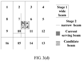
- a narrow beam whose signal strength is highest is a beam b; in this case, when a synchronization beam whose signal strength is second highest is a beam 10, in FIG. 3(b) and in FIG. 3(c) , only six narrow beams a to f close to the beam 10 whose signal strength is second highest need to be swept.
- a narrow beam whose signal strength is highest is a beam b
- a synchronization beam whose signal strength is second highest is a beam 11
- only four narrow beams a to d that surround the beam b and that are close to the beam 11 need to be swept.
- a detected synchronization beam whose signal strength is highest is used as a current serving wide beam, and each narrow beam in a coverage area of the serving wide beam is swept, to determine a narrow beam whose signal strength is highest.
- the terminal device determines, through detection, that a narrow beam whose signal strength is highest is a beam b, but in a subsequent synchronization signal sweeping process, the terminal device determines that a wide beam whose signal strength is highest is not in a wide beam 7 in which the narrow beam b is located, for example, the wide beam whose signal strength is highest is a beam 11 (or may be a beam 12, a beam 13, or another wide beam), the beam 11 (or the beam 12, the beam 13, or another wide beam) is used as a current serving wide beam. Subsequently, according to the method mentioned above, each narrow beam in a coverage area of the wide beam 11 is swept to determine a narrow beam whose signal strength is highest.
- the network device may determine a sweeping range based on the detection result reported by the terminal device, thereby reducing a quantity of swept beams in the beam adjustment process and reducing signaling overheads.
- a terminal device notifies a base station of information about a downlink narrow beam used for data communication between the base station and the terminal device.
- the terminal device may notify the corresponding base station of information about a detected narrow beam whose signal quality is higher than a specified threshold.
- the narrow beam is a beam used for data communication, and there may be one or more such narrow beams. If there is one such narrow beam, the narrow beam is a narrow beam whose signal strength is highest. If there are a plurality of such narrow beams, signal quality of all the narrow beams is higher than the specified threshold.
- the plurality of narrow beams may be a plurality of narrow beams from one base station, or may be narrow beams from a plurality of base stations.
- a detection process may be implemented by performing the foregoing beam sweeping process or beam adjustment process.
- Notification content may be one or more of the following: an OFDM symbol index of the detected narrow beam, a frame number, a subframe number, a resource location of the detected narrow beam, an antenna port number, or the like.
- the notification content may be sent through an uplink control channel, or may be carried in RRC (radio resource control, radio resource control) signaling.
- RRC radio resource control, radio resource control
- a notification process may be performed in a plurality of manners, and this is not limited in this embodiment.
- the base station determines, based on the received information about the narrow beam, a wide beam related to the narrow beam, and notifies the terminal device of information about the wide beam.
- the wide beam related to the narrow beam may be a wide beam in which the narrow beam is located, that is, a wide beam covering the narrow beam, and the terminal device may also be further notified of a wide beam surrounding the wide beam.
- the base station may also determine a wide beam that needs to be swept by the terminal device, and notify the terminal device.
- a narrow beam b whose signal strength is highest and that is aligned between the base station and the terminal device is currently located in a wide beam 7, the terminal device may be notified of information about the wide beam 7, and the terminal device may also be further notified of wide beams (beams 1 to 3, a beam 6, and beams 8 to 11) surrounding the beam 7.
- Notified beam information may be any one or more of the following: a beam ID of the wide beam, an OFDM symbol index, an antenna port number, a slot number, a subframe number, a radio frame number, and the like. This is not limited in this embodiment.
- the beam information is used by the terminal device to determine a wide beam that needs to be swept and that is spatially adjacent to the wide beam.
- the base station may directly notify the terminal device of each wide beam that needs to be swept, and the base station may also send, to the terminal device, beam information of all the wide beam 7 and wide beams 1 to 3 and wide beams 6 to 11 spatially adjacent to the wide beam 7, where all these wide beams need to be swept by the terminal device.
- the base station may determine a wide beam that needs to be swept by the terminal device, and notify the terminal device.
- the base station and the terminal device may maintain a transmit/receive (TX/RX) synchronization beam pair, and therefore, if the wide beam 7 in which the narrow beam is located and that is reported by the terminal device to the base station is still a maintained TX synchronization beam currently, the base station may not send beam information of the wide beam 7 to the terminal device, because the terminal device knows the beam information of the wide beam 7; if the wide beam 7 in which the narrow beam is located and that is reported by the terminal device to the base station is not a maintained TX synchronization beam currently, the base station may send information about the wide beam 7 to the terminal device, and may use the beam 7 as a serving wide beam of the terminal device.
- TX/RX transmit/receive
- a notification message used to notify the terminal device may be carried by using a downlink control channel, may be sent by using RRC signaling, or the like. This is not limited in this embodiment.
- the terminal device detects signal strength of each downlink wide beam.
- the terminal device performs synchronization beam detection, and detects all synchronization beams (downlink wide beam) sent by the base station. During synchronization beam detection, the terminal device measures time-frequency resources of the synchronization beams.
- the terminal device notifies the base station of a detection result of a wide beam whose signal quality satisfies a preset threshold.
- the terminal device detects signal strength of each synchronization beam, and the terminal device may compare synchronization beams 1 to 3 and beams 6 to 11 surrounding a beam 7. If a beam whose signal strength is highest is still the beam 7, and the terminal device also detects that a beam whose signal strength is second highest in the wide beams 1 to 3 and beams 6 to 11 that are adjacent to the beam 7 and that surround the beam 7 is a beam 10, the terminal device reports the beam 7 whose signal strength is highest and the beam 10 whose signal strength is second highest and that surrounds the beam 7.
- Report content may be beam information (such as a beam ID), or beam information and quality of the corresponding beam.
- the report content may be sent through an uplink control channel, or sent by using RRC signaling or the like. This is not limited in this embodiment. Certainly, because the beam whose signal strength is highest does not change, the terminal device may alternatively report only information about the beam whose signal strength is second highest.
- the terminal device detects that the synchronization beam whose signal strength is highest is still the beam 7, and also detects that a beam whose signal strength is second highest in the wide beams 1 to 3 and beams 6 to 11 that are adjacent to the beam 7 and that surround the beam 7 is a beam 11, the terminal device reports the beam 7 whose signal strength is highest and the beam 11 whose signal strength is second highest and that surrounds the beam 7.
- Report content may be beam information (such as a beam ID), or beam information and quality of the corresponding beam.
- the report content may be sent through an uplink control channel, or sent by using RRC signaling or the like. This is not limited in this embodiment.
- the terminal device may alternatively report only information about the beam whose signal strength is second highest.
- the terminal device may report, to the base station, information and signal quality of both the detected beam 7 whose signal strength is highest and that satisfies a specific signal quality threshold, and a synchronization beam that satisfies a signal quality threshold and that is in the synchronization beams 1 to 3 and beams 6 to 11 surrounding the beam 7.
- the base station determines, based on the information, a narrow beam that needs to be swept during beam adjustment.
- Report content may be beam information (such as a beam ID), or beam information and quality of the corresponding beam.
- the report content may be sent through an uplink control channel, or sent by using RRC signaling or the like. This is not limited in this embodiment.
- the base station may determine, based on the detection result, the narrow beam that needs to be swept during downlink-beam adjustment.
- the detection result indicates that the wide beam whose signal strength is highest does not change, it may be determined that each narrow beam that surrounds the narrow beam and that is close to the wide beam whose signal strength is second highest is to be swept.
- the base station determines that six beams a to f that are closest to the beam b and that are between the beam 7 and the beam 10 need to be swept in a beam adjustment process, so that the terminal device detects and reports a narrow beam that satisfies a signal quality requirement.
- the base station determines that four beams a to d that are closest to the beam b and that are between the beam 7 and the beam 11 need to be swept in a beam adjustment process, so that the terminal device detects and reports a narrow beam that satisfies a signal quality requirement.
- FIG. 3(a) , FIG. 3(b) , FIG. 3(c) , and FIG. 3(d) give some examples in which the base station determines to sweep some narrow beams surrounding the current serving narrow beam b.
- An actual operation process is not limited to implementations in FIG. 3(a) , FIG. 3(b) , FIG. 3(c) , and FIG. 3(d) , and there may be another adjustment manner.
- Step 105 Trigger a beam adjustment (Beam adjustment) process. This step is optional, and may be performed before step 104. If triggering is performed by the base station, a signaling instruction is not needed. If triggering is performed by the terminal device, the terminal device needs to send uplink signaling, to trigger the beam adjustment process.
- the uplink signaling may be sent through an uplink control channel or by using RRC signaling or the like. This is not limited in this embodiment.
- the base station sends signaling of a downlink-beam adjustment instruction to the terminal device, where the signaling may carry a resource location of the downlink narrow beam that needs to be detected, or carry a resource indication in another manner.
- the signaling is sent through a downlink control channel or by using RRC signaling or the like. This is not limited in this embodiment.
- the base station may perform narrow beam sweeping for downlink-beam adjustment, so that the terminal device performs detection on a corresponding time-frequency resource and reports a detection result.
- the base station may perform narrow beam adjustment.
- step 104 the terminal device detects that the synchronization beam whose signal strength is highest does not change and is still the wide beam 7 covering the narrow beam whose signal strength is highest.
- step 104 if the terminal device detects that the synchronization beam whose signal strength is highest has changed and is no longer the wide beam 7 covering the narrow beam whose signal strength is highest, for example, if signal strength of the beam 10 is already greater than that of the beam 7, or a beam different from the synchronization beams 1 to 3 and the beams 6 to 11 becomes the beam whose signal strength is highest, the terminal device reports the new beam whose signal strength is highest.
- Report content may be beam information, or beam information and quality of the corresponding beam.
- the report content may be sent through an uplink control channel or by using RRC signaling or the like.
- the base station updates the current serving wide beam to the new beam whose signal strength is highest and that is reported by the terminal device, and all narrow beams in a coverage area of the new serving wide beam are swept in a next beam adjustment process.
- the base station may determine, based on the wide beam detection result reported by the terminal device, the downlink narrow beam that needs to be swept, thereby reducing system overheads.
- an embodiment further discloses a network device, including:
- the receiving module is further configured to receive a detection result, reported by the terminal device, of broadcast beam detection performed based on the information about the broadcast beam.
- the determining module is further configured to determine, based on the detection result, a downlink beam that needs to be swept during downlink-beam adjustment and that is used for data communication.
- the network device is not limited to a base station, and may be a TRP or a network device of another type alternatively.
- an embodiment further discloses a terminal device, including:
- the sending module is further configured to report a detection result of the broadcast beam detection to the network device, and the detection result is used by the network device to determine a downlink beam that needs to be swept and that is used for data communication.
- the detection module is further configured to detect the downlink beam that is swept by the network device and that is used for data communication.
- a corresponding function module performs a corresponding step in the method embodiments.
- steps refer to a corresponding method.
- Other corresponding steps may also be implemented by corresponding modules, and reference may be made to descriptions in the method embodiments. Details are not described herein again.
- the receiving module may be implemented by a receiver, and the sending module may be implemented by a transmitter.
- Other corresponding function modules such as the determining module and the detection module may be implemented by a processor.
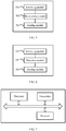
- FIG. 7 For details, refer to FIG. 7 .
- FIG. 7 For other corresponding steps, refer to the method embodiments. Details are not described herein again.
- the network device receives the detection result reported by the terminal device, and determines the downlink narrow beam that needs to be swept. This reduces the quantity of swept beams and reduces the signaling overheads.
- the components of the device in FIG. 7 may be coupled together by using a bus system.
- the bus system further includes a power bus, a control bus, and a status signal bus.
- the processor may be a central processing unit (Central Processing Unit, "CPU” for short), or the processor may be another general purpose processor, a digital signal processor (DSP), an application-specific integrated circuit (ASIC), a field programmable gate array (FPGA) or another programmable logic device, a discrete gate or transistor logic device, a discrete hardware component, or the like.
- the general purpose processor may be a microprocessor, or the processor may be any conventional processor or the like.
- the memory may include a read-only memory and a random access memory, and provide an instruction and data for the processor.
- a part of the memory may further include a non-volatile random access memory.
- the memory may further store information about a device type.
- the bus system may further include the power bus, the control bus, the status signal bus, and the like.
- various types of buses in the figure are all denoted as the bus system.
- sequence numbers of the foregoing processes do not mean execution sequences.
- the execution sequences of the processes should be determined based on functions and internal logic of the processes, but should not be construed as any limitation on implementation processes of the embodiments of this application.
- the disclosed system, apparatus, and method may be implemented in other manners.
- the described apparatus embodiment is merely an example.
- the unit division is merely logical function division and may be other division during actual implementation.
- a plurality of units or components may be combined or may be integrated into another system, or some features may be ignored or not performed.
- the displayed or discussed mutual couplings or direct couplings or communication connections may be implemented by using some interfaces.
- the indirect couplings or communication connections between the apparatuses or units may be implemented in electrical, mechanical, or other forms.
- the units described as separate parts may or may not be physically separate, and parts displayed as units may or may not be physical units, may be located in one position, or may be distributed on a plurality of network units. Some or all of the units may be selected based on actual requirements to achieve the objectives of the solutions in the embodiments.
- the functions When the functions are implemented in a form of a software functional unit and sold or used as an independent product, the functions may be stored in a computer-readable storage medium. Based on such an understanding, the technical solutions of this application essentially, or the part contributing to the prior art, or some of the technical solutions may be implemented in a form of a software product.
- the computer software product is stored in a storage medium, and includes one or more instructions for instructing a computer device (which may be a personal computer, a server, a network device, or the like) to perform all or some of the steps of the methods in the embodiments of this application.
- the foregoing storage medium includes various media that can store program code, such as a USB flash drive, a removable hard disk, a read-only memory (ROM, Read-Only Memory), a random access memory (RAM, Random Access Memory), a magnetic disk, an optical disc, or the like.
- program code such as a USB flash drive, a removable hard disk, a read-only memory (ROM, Read-Only Memory), a random access memory (RAM, Random Access Memory), a magnetic disk, an optical disc, or the like.
Landscapes
- Engineering & Computer Science (AREA)
- Computer Networks & Wireless Communication (AREA)
- Signal Processing (AREA)
- Computer Security & Cryptography (AREA)
- Mobile Radio Communication Systems (AREA)
Applications Claiming Priority (2)
| Application Number | Priority Date | Filing Date | Title |
|---|---|---|---|
| CN201611238127.2A CN108260134B (zh) | 2016-12-28 | 2016-12-28 | 一种下行波束调整的方法及装置 |
| PCT/CN2017/118681 WO2018121540A1 (zh) | 2016-12-28 | 2017-12-26 | 一种下行波束调整的方法及装置 |
Publications (3)
| Publication Number | Publication Date |
|---|---|
| EP3541108A1 true EP3541108A1 (de) | 2019-09-18 |
| EP3541108A4 EP3541108A4 (de) | 2019-11-13 |
| EP3541108B1 EP3541108B1 (de) | 2023-03-01 |
Family
ID=62706888
Family Applications (1)
| Application Number | Title | Priority Date | Filing Date |
|---|---|---|---|
| EP17887749.4A Active EP3541108B1 (de) | 2016-12-28 | 2017-12-26 | Verfahren und vorrichtung zur einstellung von downlink-strahlen |
Country Status (5)
| Country | Link |
|---|---|
| US (1) | US11070264B2 (de) |
| EP (1) | EP3541108B1 (de) |
| CN (1) | CN108260134B (de) |
| BR (1) | BR112019013231A2 (de) |
| WO (1) | WO2018121540A1 (de) |
Families Citing this family (9)
| Publication number | Priority date | Publication date | Assignee | Title |
|---|---|---|---|---|
| EP3732797B1 (de) * | 2018-01-29 | 2021-09-29 | Telefonaktiebolaget Lm Ericsson (Publ) | Strahltraining eines funksendeempfängers |
| US11012881B2 (en) * | 2018-07-06 | 2021-05-18 | Mixcomm, Inc. | Beam management methods and apparatus |
| US10972172B2 (en) * | 2018-10-05 | 2021-04-06 | Arizona Board Of Regents On Behalf Of The University Of Arizona | Method for fast beam sweeping and device discovery in 5G millimeter wave and upper centimeter-wave systems |
| CN111698761B (zh) | 2019-03-15 | 2021-10-22 | 华为技术有限公司 | 通信方法、装置、设备及系统 |
| CN110611953B (zh) * | 2019-08-16 | 2022-03-01 | 展讯半导体(南京)有限公司 | 下行波束指示方法、设备和存储介质 |
| EP4184984A4 (de) * | 2020-07-16 | 2024-04-03 | Beijing Xiaomi Mobile Software Co., Ltd. | Strahlanpassungsverfahren, strahlanpassungsvorrichtung und speichermedium |
| US11742925B2 (en) | 2020-07-30 | 2023-08-29 | Samsung Electronics Co., Ltd. | Methods and apparatus for mitigating codebook inaccuracy when using hierarchical beam operations |
| CN116233858B (zh) * | 2021-12-02 | 2026-02-27 | 展讯通信(上海)有限公司 | 一种感知方法、感知系统及感知装置 |
| US11705953B2 (en) * | 2021-12-06 | 2023-07-18 | Qualcomm Incorporated | Envelope ratio method to improve beam hierarchy design |
Family Cites Families (31)
| Publication number | Priority date | Publication date | Assignee | Title |
|---|---|---|---|---|
| US7289826B1 (en) * | 2002-04-16 | 2007-10-30 | Faulkner Interstices, Llc | Method and apparatus for beam selection in a smart antenna system |
| US8891399B2 (en) * | 2010-10-25 | 2014-11-18 | Lg Electronics Inc. | Method of reducing intercell interference in wireless communication system and apparatus thereof |
| KR101820733B1 (ko) | 2011-08-24 | 2018-01-22 | 삼성전자주식회사 | 무선통신시스템에서 빔 선택 장치 및 방법 |
| KR101847400B1 (ko) | 2011-09-01 | 2018-04-10 | 삼성전자주식회사 | 무선 통신 시스템에서 최적의 빔을 선택하기 위한 장치 및 방법 |
| KR101881847B1 (ko) * | 2012-02-21 | 2018-08-24 | 삼성전자주식회사 | 통신 시스템에서 신호를 송수신하는 방법 및 장치 |
| US9380582B2 (en) * | 2012-04-16 | 2016-06-28 | Samsung Electronics Co., Ltd. | Methods and apparatus for flexible beam communications in random access in system with large number of antennas |
| KR20130125903A (ko) * | 2012-05-10 | 2013-11-20 | 삼성전자주식회사 | 통신시스템에서 빔포밍을 수행하는 방법 및 장치 |
| KR102009743B1 (ko) * | 2012-06-29 | 2019-10-21 | 삼성전자주식회사 | 빔포밍 기반 통신 시스템에서 신호를 전송하는 방법 및 장치 |
| KR101995798B1 (ko) * | 2012-07-03 | 2019-07-03 | 삼성전자주식회사 | 빔포밍을 사용하는 통신 시스템의 랜덤 억세스 장치 및 방법 |
| KR101995266B1 (ko) * | 2012-08-17 | 2019-07-02 | 삼성전자 주식회사 | 빔포밍을 이용한 시스템에서 시스템 액세스 방법 및 장치 |
| KR102029102B1 (ko) * | 2012-11-19 | 2019-11-11 | 삼성전자주식회사 | 빔포밍 시스템에서 빔 방향 선택 방법 및 장치 |
| KR102085003B1 (ko) * | 2013-04-30 | 2020-04-14 | 삼성전자주식회사 | 빔포밍 시스템에서 최적의 송수신 빔 제공 방법 및 장치 |
| WO2015086080A1 (en) * | 2013-12-12 | 2015-06-18 | Telefonaktiebolaget L M Ericsson (Publ) | Method and network node for broadcasting |
| CN103716081B (zh) * | 2013-12-20 | 2019-08-06 | 中兴通讯股份有限公司 | 下行波束确定方法、装置及系统 |
| CN104734761A (zh) * | 2013-12-20 | 2015-06-24 | 中兴通讯股份有限公司 | 一种上下行波束混合指示的方法、基站、终端和系统 |
| US9578644B2 (en) * | 2014-09-26 | 2017-02-21 | Mediatek Inc. | Beam misalignment detection for wireless communication system with beamforming |
| WO2016065644A1 (zh) * | 2014-10-31 | 2016-05-06 | 华为技术有限公司 | 一种波束调整的方法、用户设备和基站 |
| US20190104549A1 (en) * | 2014-11-26 | 2019-04-04 | Idac Holdings, Inc. | Initial access in high frequency wireless systems |
| CN105991175B (zh) | 2015-01-29 | 2019-02-05 | 电信科学技术研究院 | 一种导频信号的发送、接收处理方法及装置 |
| CN105897322B (zh) * | 2015-02-17 | 2019-02-22 | 财团法人工业技术研究院 | 毫米波通信的波束形成方法及其基站与用户设备 |
| ES2809721T3 (es) * | 2015-05-22 | 2021-03-05 | Asustek Comp Inc | Transmisiones de señal de referencia en un sistema de comunicación inalámbrica |
| WO2017022870A1 (en) * | 2015-08-03 | 2017-02-09 | Samsung Electronics Co., Ltd. | Method and apparatus for initial access in wireless communication system |
| EP3381134B1 (de) * | 2015-11-23 | 2026-02-18 | Nokia Solutions and Networks Oy | Benutzervorrichtungsstrahlformungstraining in drahtlosen netzwerken |
| CN110166085B (zh) * | 2015-12-29 | 2020-08-07 | 华为技术有限公司 | 一种下行数据传输方法及设备 |
| US10700752B2 (en) * | 2016-01-14 | 2020-06-30 | Samsung Electronics Co., Ltd. | System, method, and apparatus of beam-tracking and beam feedback operation in a beam-forming based system |
| US10270514B2 (en) * | 2016-01-14 | 2019-04-23 | Samsung Electronics Co., Ltd. | Method and apparatus for generating beam measurement information in a wireless communication system |
| PL3425970T3 (pl) * | 2016-06-21 | 2021-12-13 | Guangdong Oppo Mobile Telecommunications Corp., Ltd. | Wysyłanie informacji o wskazaniu kanału nadawania |
| CN108023629A (zh) * | 2016-11-03 | 2018-05-11 | 株式会社Ntt都科摩 | 波束确定方法、下行传输解调方法、用户设备和基站 |
| US10567058B2 (en) * | 2017-02-08 | 2020-02-18 | Samsung Electronics Co., Ltd. | Method and apparatus for beam management |
| US10708919B2 (en) * | 2017-11-07 | 2020-07-07 | Qualcomm Incorporated | Techniques and apparatuses for beam management to overcome maximum permissible exposure conditions |
| CA3060803A1 (en) * | 2018-10-31 | 2020-04-30 | Comcast Cable Communications, Llc | Beam management for cells in wireless communications |
-
2016
- 2016-12-28 CN CN201611238127.2A patent/CN108260134B/zh active Active
-
2017
- 2017-12-26 WO PCT/CN2017/118681 patent/WO2018121540A1/zh not_active Ceased
- 2017-12-26 BR BR112019013231A patent/BR112019013231A2/pt not_active IP Right Cessation
- 2017-12-26 EP EP17887749.4A patent/EP3541108B1/de active Active
-
2019
- 2019-06-28 US US16/455,786 patent/US11070264B2/en active Active
Also Published As
| Publication number | Publication date |
|---|---|
| BR112019013231A2 (pt) | 2019-12-24 |
| EP3541108A4 (de) | 2019-11-13 |
| CN108260134A (zh) | 2018-07-06 |
| US11070264B2 (en) | 2021-07-20 |
| US20190349049A1 (en) | 2019-11-14 |
| EP3541108B1 (de) | 2023-03-01 |
| WO2018121540A1 (zh) | 2018-07-05 |
| CN108260134B (zh) | 2023-12-29 |
Similar Documents
| Publication | Publication Date | Title |
|---|---|---|
| US11070264B2 (en) | Downlink-beam adjustment method and apparatus | |
| US11595108B2 (en) | Wireless communication method, network device, and terminal device | |
| US11064492B2 (en) | Resource configuration method and apparatus | |
| US10925034B2 (en) | Resource indication method, apparatus, and system | |
| US10893429B2 (en) | Uplink measurement signal indication method and apparatus | |
| CN107889220B (zh) | 通信方法、基站和终端设备 | |
| US12170564B2 (en) | Beam training method and device, communication system | |
| US10862652B2 (en) | Uplink signal acknowledge method and apparatus | |
| CN110168957A (zh) | 基站控制的波束管理 | |
| CN113840375B (zh) | 用于寻呼的方法和装置 | |
| KR20170106446A (ko) | Ue의 위치를 획득하는 방법, 및 장치 | |
| US20230093234A1 (en) | Uplink measurement management method, apparatus, and system | |
| CN107872293B (zh) | 信号传输方法和装置 | |
| CN111756426B (zh) | 一种选择接收波束的方法及装置 | |
| EP3776731B1 (de) | Verfahren und vorrichtung zur auswahl des millimeterwellen-mimo-modus | |
| US20190280786A1 (en) | Method for transmitting measurement signal and apparatus | |
| US20250183988A1 (en) | User equipment reception beam refinement based on measurement of second user equipment | |
| WO2024031328A1 (en) | Link quality monitoring on multiple candidate cell groups | |
| CN108809368B (zh) | 一种波束管理方法及其装置 |
Legal Events
| Date | Code | Title | Description |
|---|---|---|---|
| STAA | Information on the status of an ep patent application or granted ep patent |
Free format text: STATUS: THE INTERNATIONAL PUBLICATION HAS BEEN MADE |
|
| PUAI | Public reference made under article 153(3) epc to a published international application that has entered the european phase |
Free format text: ORIGINAL CODE: 0009012 |
|
| STAA | Information on the status of an ep patent application or granted ep patent |
Free format text: STATUS: REQUEST FOR EXAMINATION WAS MADE |
|
| 17P | Request for examination filed |
Effective date: 20190614 |
|
| AK | Designated contracting states |
Kind code of ref document: A1 Designated state(s): AL AT BE BG CH CY CZ DE DK EE ES FI FR GB GR HR HU IE IS IT LI LT LU LV MC MK MT NL NO PL PT RO RS SE SI SK SM TR |
|
| AX | Request for extension of the european patent |
Extension state: BA ME |
|
| A4 | Supplementary search report drawn up and despatched |
Effective date: 20191015 |
|
| RIC1 | Information provided on ipc code assigned before grant |
Ipc: H04W 16/28 20090101AFI20191009BHEP |
|
| DAV | Request for validation of the european patent (deleted) | ||
| DAX | Request for extension of the european patent (deleted) | ||
| STAA | Information on the status of an ep patent application or granted ep patent |
Free format text: STATUS: EXAMINATION IS IN PROGRESS |
|
| 17Q | First examination report despatched |
Effective date: 20210303 |
|
| RIC1 | Information provided on ipc code assigned before grant |
Ipc: H04W 16/28 20090101AFI20220907BHEP |
|
| GRAP | Despatch of communication of intention to grant a patent |
Free format text: ORIGINAL CODE: EPIDOSNIGR1 |
|
| STAA | Information on the status of an ep patent application or granted ep patent |
Free format text: STATUS: GRANT OF PATENT IS INTENDED |
|
| INTG | Intention to grant announced |
Effective date: 20221018 |
|
| GRAS | Grant fee paid |
Free format text: ORIGINAL CODE: EPIDOSNIGR3 |
|
| GRAA | (expected) grant |
Free format text: ORIGINAL CODE: 0009210 |
|
| STAA | Information on the status of an ep patent application or granted ep patent |
Free format text: STATUS: THE PATENT HAS BEEN GRANTED |
|
| AK | Designated contracting states |
Kind code of ref document: B1 Designated state(s): AL AT BE BG CH CY CZ DE DK EE ES FI FR GB GR HR HU IE IS IT LI LT LU LV MC MK MT NL NO PL PT RO RS SE SI SK SM TR |
|
| REG | Reference to a national code |
Ref country code: GB Ref legal event code: FG4D |
|
| REG | Reference to a national code |
Ref country code: CH Ref legal event code: EP Ref country code: AT Ref legal event code: REF Ref document number: 1551869 Country of ref document: AT Kind code of ref document: T Effective date: 20230315 |
|
| REG | Reference to a national code |
Ref country code: DE Ref legal event code: R096 Ref document number: 602017066508 Country of ref document: DE |
|
| REG | Reference to a national code |
Ref country code: IE Ref legal event code: FG4D |
|
| REG | Reference to a national code |
Ref country code: LT Ref legal event code: MG9D |
|
| REG | Reference to a national code |
Ref country code: NL Ref legal event code: MP Effective date: 20230301 |
|
| PG25 | Lapsed in a contracting state [announced via postgrant information from national office to epo] |
Ref country code: RS Free format text: LAPSE BECAUSE OF FAILURE TO SUBMIT A TRANSLATION OF THE DESCRIPTION OR TO PAY THE FEE WITHIN THE PRESCRIBED TIME-LIMIT Effective date: 20230301 Ref country code: NO Free format text: LAPSE BECAUSE OF FAILURE TO SUBMIT A TRANSLATION OF THE DESCRIPTION OR TO PAY THE FEE WITHIN THE PRESCRIBED TIME-LIMIT Effective date: 20230601 Ref country code: LV Free format text: LAPSE BECAUSE OF FAILURE TO SUBMIT A TRANSLATION OF THE DESCRIPTION OR TO PAY THE FEE WITHIN THE PRESCRIBED TIME-LIMIT Effective date: 20230301 Ref country code: LT Free format text: LAPSE BECAUSE OF FAILURE TO SUBMIT A TRANSLATION OF THE DESCRIPTION OR TO PAY THE FEE WITHIN THE PRESCRIBED TIME-LIMIT Effective date: 20230301 Ref country code: HR Free format text: LAPSE BECAUSE OF FAILURE TO SUBMIT A TRANSLATION OF THE DESCRIPTION OR TO PAY THE FEE WITHIN THE PRESCRIBED TIME-LIMIT Effective date: 20230301 Ref country code: ES Free format text: LAPSE BECAUSE OF FAILURE TO SUBMIT A TRANSLATION OF THE DESCRIPTION OR TO PAY THE FEE WITHIN THE PRESCRIBED TIME-LIMIT Effective date: 20230301 |
|
| REG | Reference to a national code |
Ref country code: AT Ref legal event code: MK05 Ref document number: 1551869 Country of ref document: AT Kind code of ref document: T Effective date: 20230301 |
|
| PG25 | Lapsed in a contracting state [announced via postgrant information from national office to epo] |
Ref country code: SE Free format text: LAPSE BECAUSE OF FAILURE TO SUBMIT A TRANSLATION OF THE DESCRIPTION OR TO PAY THE FEE WITHIN THE PRESCRIBED TIME-LIMIT Effective date: 20230301 Ref country code: PL Free format text: LAPSE BECAUSE OF FAILURE TO SUBMIT A TRANSLATION OF THE DESCRIPTION OR TO PAY THE FEE WITHIN THE PRESCRIBED TIME-LIMIT Effective date: 20230301 Ref country code: NL Free format text: LAPSE BECAUSE OF FAILURE TO SUBMIT A TRANSLATION OF THE DESCRIPTION OR TO PAY THE FEE WITHIN THE PRESCRIBED TIME-LIMIT Effective date: 20230301 Ref country code: GR Free format text: LAPSE BECAUSE OF FAILURE TO SUBMIT A TRANSLATION OF THE DESCRIPTION OR TO PAY THE FEE WITHIN THE PRESCRIBED TIME-LIMIT Effective date: 20230602 Ref country code: FI Free format text: LAPSE BECAUSE OF FAILURE TO SUBMIT A TRANSLATION OF THE DESCRIPTION OR TO PAY THE FEE WITHIN THE PRESCRIBED TIME-LIMIT Effective date: 20230301 |
|
| PG25 | Lapsed in a contracting state [announced via postgrant information from national office to epo] |
Ref country code: SM Free format text: LAPSE BECAUSE OF FAILURE TO SUBMIT A TRANSLATION OF THE DESCRIPTION OR TO PAY THE FEE WITHIN THE PRESCRIBED TIME-LIMIT Effective date: 20230301 Ref country code: RO Free format text: LAPSE BECAUSE OF FAILURE TO SUBMIT A TRANSLATION OF THE DESCRIPTION OR TO PAY THE FEE WITHIN THE PRESCRIBED TIME-LIMIT Effective date: 20230301 Ref country code: PT Free format text: LAPSE BECAUSE OF FAILURE TO SUBMIT A TRANSLATION OF THE DESCRIPTION OR TO PAY THE FEE WITHIN THE PRESCRIBED TIME-LIMIT Effective date: 20230703 Ref country code: EE Free format text: LAPSE BECAUSE OF FAILURE TO SUBMIT A TRANSLATION OF THE DESCRIPTION OR TO PAY THE FEE WITHIN THE PRESCRIBED TIME-LIMIT Effective date: 20230301 Ref country code: CZ Free format text: LAPSE BECAUSE OF FAILURE TO SUBMIT A TRANSLATION OF THE DESCRIPTION OR TO PAY THE FEE WITHIN THE PRESCRIBED TIME-LIMIT Effective date: 20230301 Ref country code: AT Free format text: LAPSE BECAUSE OF FAILURE TO SUBMIT A TRANSLATION OF THE DESCRIPTION OR TO PAY THE FEE WITHIN THE PRESCRIBED TIME-LIMIT Effective date: 20230301 |
|
| PG25 | Lapsed in a contracting state [announced via postgrant information from national office to epo] |
Ref country code: SK Free format text: LAPSE BECAUSE OF FAILURE TO SUBMIT A TRANSLATION OF THE DESCRIPTION OR TO PAY THE FEE WITHIN THE PRESCRIBED TIME-LIMIT Effective date: 20230301 Ref country code: IS Free format text: LAPSE BECAUSE OF FAILURE TO SUBMIT A TRANSLATION OF THE DESCRIPTION OR TO PAY THE FEE WITHIN THE PRESCRIBED TIME-LIMIT Effective date: 20230701 |
|
| REG | Reference to a national code |
Ref country code: DE Ref legal event code: R097 Ref document number: 602017066508 Country of ref document: DE |
|
| PLBE | No opposition filed within time limit |
Free format text: ORIGINAL CODE: 0009261 |
|
| STAA | Information on the status of an ep patent application or granted ep patent |
Free format text: STATUS: NO OPPOSITION FILED WITHIN TIME LIMIT |
|
| PG25 | Lapsed in a contracting state [announced via postgrant information from national office to epo] |
Ref country code: SI Free format text: LAPSE BECAUSE OF FAILURE TO SUBMIT A TRANSLATION OF THE DESCRIPTION OR TO PAY THE FEE WITHIN THE PRESCRIBED TIME-LIMIT Effective date: 20230301 Ref country code: DK Free format text: LAPSE BECAUSE OF FAILURE TO SUBMIT A TRANSLATION OF THE DESCRIPTION OR TO PAY THE FEE WITHIN THE PRESCRIBED TIME-LIMIT Effective date: 20230301 |
|
| 26N | No opposition filed |
Effective date: 20231204 |
|
| PG25 | Lapsed in a contracting state [announced via postgrant information from national office to epo] |
Ref country code: IT Free format text: LAPSE BECAUSE OF FAILURE TO SUBMIT A TRANSLATION OF THE DESCRIPTION OR TO PAY THE FEE WITHIN THE PRESCRIBED TIME-LIMIT Effective date: 20230301 |
|
| REG | Reference to a national code |
Ref country code: DE Ref legal event code: R119 Ref document number: 602017066508 Country of ref document: DE |
|
| REG | Reference to a national code |
Ref country code: CH Ref legal event code: PL |
|
| PG25 | Lapsed in a contracting state [announced via postgrant information from national office to epo] |
Ref country code: LU Free format text: LAPSE BECAUSE OF NON-PAYMENT OF DUE FEES Effective date: 20231226 |
|
| PG25 | Lapsed in a contracting state [announced via postgrant information from national office to epo] |
Ref country code: MC Free format text: LAPSE BECAUSE OF FAILURE TO SUBMIT A TRANSLATION OF THE DESCRIPTION OR TO PAY THE FEE WITHIN THE PRESCRIBED TIME-LIMIT Effective date: 20230301 |
|
| REG | Reference to a national code |
Ref country code: BE Ref legal event code: MM Effective date: 20231231 |
|
| PG25 | Lapsed in a contracting state [announced via postgrant information from national office to epo] |
Ref country code: MC Free format text: LAPSE BECAUSE OF FAILURE TO SUBMIT A TRANSLATION OF THE DESCRIPTION OR TO PAY THE FEE WITHIN THE PRESCRIBED TIME-LIMIT Effective date: 20230301 Ref country code: LU Free format text: LAPSE BECAUSE OF NON-PAYMENT OF DUE FEES Effective date: 20231226 |
|
| REG | Reference to a national code |
Ref country code: IE Ref legal event code: MM4A |
|
| PG25 | Lapsed in a contracting state [announced via postgrant information from national office to epo] |
Ref country code: IE Free format text: LAPSE BECAUSE OF NON-PAYMENT OF DUE FEES Effective date: 20231226 Ref country code: DE Free format text: LAPSE BECAUSE OF NON-PAYMENT OF DUE FEES Effective date: 20240702 |
|
| PG25 | Lapsed in a contracting state [announced via postgrant information from national office to epo] |
Ref country code: BE Free format text: LAPSE BECAUSE OF NON-PAYMENT OF DUE FEES Effective date: 20231231 |
|
| PG25 | Lapsed in a contracting state [announced via postgrant information from national office to epo] |
Ref country code: FR Free format text: LAPSE BECAUSE OF NON-PAYMENT OF DUE FEES Effective date: 20231231 |
|
| PG25 | Lapsed in a contracting state [announced via postgrant information from national office to epo] |
Ref country code: CH Free format text: LAPSE BECAUSE OF NON-PAYMENT OF DUE FEES Effective date: 20231231 |
|
| PG25 | Lapsed in a contracting state [announced via postgrant information from national office to epo] |
Ref country code: IE Free format text: LAPSE BECAUSE OF NON-PAYMENT OF DUE FEES Effective date: 20231226 Ref country code: FR Free format text: LAPSE BECAUSE OF NON-PAYMENT OF DUE FEES Effective date: 20231231 Ref country code: DE Free format text: LAPSE BECAUSE OF NON-PAYMENT OF DUE FEES Effective date: 20240702 Ref country code: CH Free format text: LAPSE BECAUSE OF NON-PAYMENT OF DUE FEES Effective date: 20231231 Ref country code: BE Free format text: LAPSE BECAUSE OF NON-PAYMENT OF DUE FEES Effective date: 20231231 |
|
| PG25 | Lapsed in a contracting state [announced via postgrant information from national office to epo] |
Ref country code: BG Free format text: LAPSE BECAUSE OF FAILURE TO SUBMIT A TRANSLATION OF THE DESCRIPTION OR TO PAY THE FEE WITHIN THE PRESCRIBED TIME-LIMIT Effective date: 20230301 |
|
| PG25 | Lapsed in a contracting state [announced via postgrant information from national office to epo] |
Ref country code: BG Free format text: LAPSE BECAUSE OF FAILURE TO SUBMIT A TRANSLATION OF THE DESCRIPTION OR TO PAY THE FEE WITHIN THE PRESCRIBED TIME-LIMIT Effective date: 20230301 |
|
| PG25 | Lapsed in a contracting state [announced via postgrant information from national office to epo] |
Ref country code: CY Free format text: LAPSE BECAUSE OF FAILURE TO SUBMIT A TRANSLATION OF THE DESCRIPTION OR TO PAY THE FEE WITHIN THE PRESCRIBED TIME-LIMIT; INVALID AB INITIO Effective date: 20171226 |
|
| PG25 | Lapsed in a contracting state [announced via postgrant information from national office to epo] |
Ref country code: HU Free format text: LAPSE BECAUSE OF FAILURE TO SUBMIT A TRANSLATION OF THE DESCRIPTION OR TO PAY THE FEE WITHIN THE PRESCRIBED TIME-LIMIT; INVALID AB INITIO Effective date: 20171226 |
|
| PG25 | Lapsed in a contracting state [announced via postgrant information from national office to epo] |
Ref country code: TR Free format text: LAPSE BECAUSE OF FAILURE TO SUBMIT A TRANSLATION OF THE DESCRIPTION OR TO PAY THE FEE WITHIN THE PRESCRIBED TIME-LIMIT Effective date: 20230301 |
|
| PGFP | Annual fee paid to national office [announced via postgrant information from national office to epo] |
Ref country code: GB Payment date: 20251114 Year of fee payment: 9 |