EP3541190B1 - Verfahren und vorrichtung zur verarbeitung von sich nacheinander entlang eines weges bewegenden geflügelteilen - Google Patents
Verfahren und vorrichtung zur verarbeitung von sich nacheinander entlang eines weges bewegenden geflügelteilen Download PDFInfo
- Publication number
- EP3541190B1 EP3541190B1 EP17817235.9A EP17817235A EP3541190B1 EP 3541190 B1 EP3541190 B1 EP 3541190B1 EP 17817235 A EP17817235 A EP 17817235A EP 3541190 B1 EP3541190 B1 EP 3541190B1
- Authority
- EP
- European Patent Office
- Prior art keywords
- conveyor
- processing
- poultry parts
- poultry
- carriers
- Prior art date
- Legal status (The legal status is an assumption and is not a legal conclusion. Google has not performed a legal analysis and makes no representation as to the accuracy of the status listed.)
- Active
Links
Images


Classifications
-
- A—HUMAN NECESSITIES
- A22—BUTCHERING; MEAT TREATMENT; PROCESSING POULTRY OR FISH
- A22C—PROCESSING MEAT, POULTRY, OR FISH
- A22C21/00—Processing poultry
- A22C21/0053—Transferring or conveying devices for poultry
-
- B—PERFORMING OPERATIONS; TRANSPORTING
- B65—CONVEYING; PACKING; STORING; HANDLING THIN OR FILAMENTARY MATERIAL
- B65G—TRANSPORT OR STORAGE DEVICES, e.g. CONVEYORS FOR LOADING OR TIPPING, SHOP CONVEYOR SYSTEMS OR PNEUMATIC TUBE CONVEYORS
- B65G47/00—Article or material-handling devices associated with conveyors; Methods employing such devices
- B65G47/74—Feeding, transfer, or discharging devices of particular kinds or types
- B65G47/84—Star-shaped wheels or devices having endless travelling belts or chains, the wheels or devices being equipped with article-engaging elements
- B65G47/841—Devices having endless travelling belts or chains equipped with article-engaging elements
- B65G47/844—Devices having endless travelling belts or chains equipped with article-engaging elements the article-engaging elements being pushers transversally movable on the supporting surface, e.g. pusher-shoes
-
- A—HUMAN NECESSITIES
- A22—BUTCHERING; MEAT TREATMENT; PROCESSING POULTRY OR FISH
- A22C—PROCESSING MEAT, POULTRY, OR FISH
- A22C21/00—Processing poultry
- A22C21/0023—Dividing poultry
- A22C21/003—Filleting poultry, i.e. extracting, cutting or shaping poultry fillets
-
- A—HUMAN NECESSITIES
- A22—BUTCHERING; MEAT TREATMENT; PROCESSING POULTRY OR FISH
- A22C—PROCESSING MEAT, POULTRY, OR FISH
- A22C21/00—Processing poultry
- A22C21/0069—Deboning poultry or parts of poultry
-
- B—PERFORMING OPERATIONS; TRANSPORTING
- B65—CONVEYING; PACKING; STORING; HANDLING THIN OR FILAMENTARY MATERIAL
- B65G—TRANSPORT OR STORAGE DEVICES, e.g. CONVEYORS FOR LOADING OR TIPPING, SHOP CONVEYOR SYSTEMS OR PNEUMATIC TUBE CONVEYORS
- B65G2207/00—Indexing codes relating to constructional details, configuration and additional features of a handling device, e.g. Conveyors
- B65G2207/36—Pushing shoes on conveyors
-
- B—PERFORMING OPERATIONS; TRANSPORTING
- B65—CONVEYING; PACKING; STORING; HANDLING THIN OR FILAMENTARY MATERIAL
- B65G—TRANSPORT OR STORAGE DEVICES, e.g. CONVEYORS FOR LOADING OR TIPPING, SHOP CONVEYOR SYSTEMS OR PNEUMATIC TUBE CONVEYORS
- B65G47/00—Article or material-handling devices associated with conveyors; Methods employing such devices
- B65G47/22—Devices influencing the relative position or the attitude of articles during transit by conveyors
- B65G47/26—Devices influencing the relative position or the attitude of articles during transit by conveyors arranging the articles, e.g. varying spacing between individual articles
- B65G47/28—Devices influencing the relative position or the attitude of articles during transit by conveyors arranging the articles, e.g. varying spacing between individual articles during transit by a single conveyor
Definitions
- the invention relates to a novel method for processing meat products in a path of conveyance, and an improved conveying system for enabling the novel method of processing meat products.
- CA954660A discloses a method and apparatus for eviscerating poultry comprising a dividing mechanism for dividing birds into groups as they are conveyed along a processing line.
- a common phenomenon of the trend towards increasing speed of meat processing is that of larger sized machines, and as a result occupation of more floor space. Not only is the so required floor space hard to find in existing operations, it also often results in investment and capital destruction because a move to larger premises cannot be postponed to such a time that the existing premises have returned their full investment. Also often the smaller meat processing operations loose this battle for increased efficiency, and have to close down or worse become a victim of bankruptcy. Whereas increased meat processing efficiency does serve a general interest, a loss of employment by meat processing operations going out of business clearly does not.
- the invention provides for a method and apparatus as defined in one or more of the appended claims.
- the invention relates to a method for processing poultry parts moving in succession along a path of conveyance, providing a conveyor arranged to convey a succession of poultry parts along the path of conveyance downstream of a loading area, loading the poultry parts on the conveyor in the loading area, while operating the conveyor to convey the poultry parts in succession, providing a transfer means in the path of conveyance downstream of the loading area, operating the transfer means to divide the succession of poultry parts into at least two parallel streams, and performing at least two processing steps in a side-by-side arrangement at a location downstream along the path of conveyance coinciding with the at least two parallel streams, and effective to process each poultry part, while the poultry parts are divided into the at least two parallel streams.
- the arrangement of conveying and processing in parallel streams and duplication of the performing of processing steps allows increase of processing speed and throughput with little or no increase of floor space requirements. This clearly benefits existing meat processing plants, and avoids unnecessary investments in buildings and/or relocations.
- the conveyor can conveniently be provided as an endless conveyor.
- the poultry parts can be supported by carriers being provided with the conveyor.
- poultry breast caps for filleting are best supported on carriers as is known in the art. While the present invention is useful for breast cap filleting the principle of performing identical or different processing steps in a side-by-side arrangement along a path of conveyance in at least two parallel streams, can also be applied with the same benefits when harvesting meat from suspended articles of poultry.
- the at least two processing steps can also be performed simultaneously, and/or the at least two processing steps can be identical for each divided stream. It is hence also possible to process the poultry parts in one parallel stream differently from the poultry parts in the other parallel stream.
- either deskinning, or separating inner and outer fillets can be optional processing steps each applied to one stream, but not to the other.
- the invention also relates to an apparatus for processing poultry parts moving in succession along a processing path, the apparatus comprising a conveyor defining the processing path and arranged to convey a succession of carriers for poultry parts along the processing path, a transfer mechanism arranged to divide the succession of poultry parts into at least two parallel streams, and downstream of the transfer mechanism either at least two identical or different processing units in a side-by-side arrangement or at least one single processing unit capable of processing poultry parts on at least two side-by-side carriers in the at least two parallel streams to process at least two poultry parts, while the poultry parts are distributed substantially equally over the at least two parallel streams.
- the conveyor of such an apparatus can conveniently be in the form of an endless conveyor.
- a suitable form of conveyor, when the apparatus is arranged for breast cap filleting is an endless conveyor that defines an upper stretch and a lower stretch extending between first and second redirecting rollers.
- the conveyor of the apparatus may also include a plurality of first and second carriers, each for supporting a poultry part.
- each of the first and second carriers can have a base part for connection to the conveyor.
- first carriers alternating with second carriers can be each arranged on successive pairs of first and second transverse bars that define chain links of the endless conveyor.
- each base part conveniently can comprise first and second transverse bores for engaging the first and second transverse bars of each pair.
- the transfer mechanism can comprise a diagonal guide bar positioned for engagement by only the second carriers.
- each of the second carriers can then have a projecting guide roller for engaging the diagonal guide bar.
- At least one of the first and second redirecting rollers of the conveyor can be driven by a motor.
- at least one of the first and second redirecting rollers can comprise first and second lateral wheels.
- the first and second lateral wheels can be mounted on a central shaft.
- the first and second lateral wheels can be notched at their circumference to engage the pairs of first and second transverse bars defining the chain links of the conveyor.
- the transfer mechanism comprises a diagonal guide bar positioned for engagement by only the second carriers, the diagonal guide bar can positioned between the first and second lateral wheels of at least one of the first and second redirecting rollers.
- a particular embodiment of the conveying method and apparatus according to the invention can form part of a an apparatus for processing eviscerated poultry carcasses, such as for separating and removing fillets of meat from skeletal breast structures of chickens, turkeys or other birds.
- the apparatus then further includes meat processing stations for filleting poultry breast caps, and optionally at least one de-skinner unit downstream of the transfer mechanism.
- Such an apparatus may further also include one or more of a pair of identical wishbone removing units, a pair of identical first breast fillet removing units, a pair of identical breast fillet cutters, and/or a pair of identical second breast fillet removing units all downstream of the transfer mechanism, and each unit of a pair in a side-by-side arrangement with the other unit of the same pair.
- Units in each pair can optionally also be arranged for deactivation to skip one or more processing steps for the poultry parts conveyed in one of the at least two parallel streams.
- the machine for deboning and filleting breast caps can advantageous make use of an endless conveyor that defines an upper stretch and a lower stretch each extending between opposite first and second redirecting rollers.
- the upper stretch, or a part thereof, can then be used as a loading area.
- the lower stretch conveying the breast cap carriers in an upside-down position, downstream of the transfer mechanism, can then be used to locate the individual meat processing units.
- the conveyor is operated to convey the poultry parts in succession to the transfer mechanism.
- the carriers In the loading area the carriers can have a closer and more compact spacing than in the processing area, the carrier spacing along a conveyor in conventional meat processing apparatuses is accordingly dictated by the processing units.
- the present invention as clarified by the examples given, allows the carrier spacing, and thereby the poultry part spacing to be adapted to the loading requirements, while at then same time allowing the spacing to be doubled for the processing units.
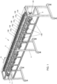
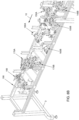
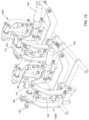
- a meat processing machine 1 has a support frame 3, and an endless conveyor 5.
- the endless conveyor 5 has a first redirecting roller 7, and a second redirecting roller 9, which are spaced from one another so as to cause the endless conveyor 5 to have parallel upper and lower stretches. It is to be understood that treatment stations can be provided along the lower stretch of the conveyor 5, but for clarity these have been omitted in Figure 1 .
- a drive motor 11 Associated with the first redirecting roller 7 is a drive motor 11, for moving the conveyor via the first redirecting roller 7 to define a path of conveyance in a direction of arrow 10 towards the second redirecting roller 9.
- a plurality of individual carriers that are moved along with the conveyor 5.
- the individual carriers of the plurality of carriers are aligned along the upper parallel stretch of the conveyor as a cascade of interspersed substantially identical first and second carriers 13A, 13B.
- first and second carriers 13A, 13B At the lower of the parallel conveyor stretches the first carriers 13A are seen to remain aligned on the same longitudinal side of the meat processing machine 1, while the second carriers 13B have moved to an opposite longitudinal side of the meat processing machine 1.
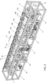
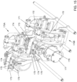
- Figure 2 shows a meat processing machine similar to Figure 1 , but with the addition of a turning station 14, as well as a variety of meat processing stations 15, 17, 19, 21, 23, 25 along the lower parallel conveyor stretch.
- the turnings station 14, when passed by each of the first and second carriers 13A, 13B, causes mandrels mounted thereon to be rotated through 180 degrees, as shown in the right hand part of Figure 2 .
- the mandrels will be further described herein below and be referred to by a reference numeral 39.
- a first meat processing station 15 is a de-skinner unit that is powered by a drive motor 16.
- This de-skinner is similar to that described in US 9078453 , but is wider to enable de-skinning of poultry breasts, suspended in parallel tracks from first and second carriers 13A, 13B.
- the furcular removers 17 can form part of a poultry breast filleting system, as described in co-pending Netherlands patent application NL 2015436 .
- a next meat processing station is composed of a pair of side-by-side first breast fillet removing units 19.
- the first breast fillet removing units 19 are followed by a pair of identical breast fillet cutters 21, which each cut a breast cap held on a respective carrier 13A, 13B along its keel bone.
- the so cut breast caps are then conveyed towards a pair of side-by-side and identical second breast fillet removing units 23, where inner and outer breast fillets can be separated.
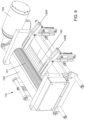
- the second carrier 13B shown in Figure 4 differs slightly from the first carrier 13A shown in Figure 3 by a roller 27 projecting form an inwardly directed side of a base part 29.
- the base part 29 is identical for each of the first and second carriers 13A, 13B and has first and second transverse bores 31, 33.
- each of the first and second carriers 13A, 13B are laterally slideable on first and second transverse bars 35, 37 of each conveyor chain link of the endless conveyor 5, as best shown in Figures 2 and 6 .
- the first transverse bore 31 thereby engaging the second transverse bar37
- the second transverse bore 33 engaging the first transverse bar 35.
- Each first and second carrier 13A, 13B has a mandrel 39 extending from an outwardly directed surface of the base part 29.
- Each mandrel 39 may be rotatable with respect to the base part 29 about an axis extending orthogonally from the outwardly directed surface of the base part 29. A more detailed description of these mandrels 39 goes beyond the subject of the present invention and is thereby redundant.
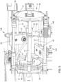
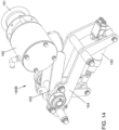
- the second redirecting roller 9 is composed of a central shaft 41, and opposite lateral notched first and second lateral wheels 43, 45 for engaging the first and second transverse bars 35, 37 within circumferential notches.
- Parallel to the central shaft 41 is a stationary bar 47, which is attached to the support frame 3.
- a first L-shaped bracket 49 having an upwardly directed leg 51 is positioned adjacent the first lateral wheel 43 of the redirecting roller 9.
- a second L-shaped bracket 53 having a downwardly directed leg 55 is positioned closer to the second lateral wheel 45 of the redirecting roller 9.
- a diagonal guide bar 57 is attached to the upstanding leg 51 and the downwardly extending leg 55 of the respective first and second L-shaped brackets 49, 53 and extends there between to be held in a stationary position with respect to the redirecting roller 9.
- first and second carriers 13A, 13B are realigned at the first redirecting roller 7 before returning to the upper stretch of the endless conveyor 5.
- FIG. 6 Also seen in Figure 6 is the turning station 14, which reverses the mandrels 39 downstream of the turning station 14 in the direction of arrow 10.
- This reversed position of the mandrel 39 causes the poultry breast caps to be rotated through 180 degrees to be positioned for de-skinning.
- Other processing steps may require the mandrels to be rotated again differently, for which similar turning stations may additionally be provided along the path of conveyance.
- Such mechanisms are conventional, and do not require further explanation.
- FIGs 7A and 7B The meat processing machine 1 as shown in Figure 1 in simplified form to expose its endless conveyor, is now shown in full in Figures 7A and 7B .
- the moving parts are shielded by safety hatches 101 and 103 on opposite sides of the machine.
- FIG 7A these safety hatches 101, 103 are shown in an opened position, and the machine 1 is conveniently arranged to be inoperative when any one of the safety hatches is not in a closed position.
- Figure 7B shows all the hatches (only hatches 101 being visible) in their closed position. It is further visible in Figure 7B that a loading platform is protected by a balustrade 105.
- the machine 1 as shown in Figures 7A and 7B is also provided with a control cabinet 107.
- Receiving containers 109 can be placed underneath the support frame 3 for receiving harvested meat or by-products of meat processing.
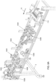
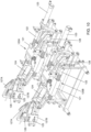
- a double de-skinner unit 110 as shown in Figure 8A acts as a first meat processing station.
- the de-skinner unit 110 is followed by a pair of wishbone removers 120A, 120B, which act as a second meat processing station. While the wishbone removers 120A, 120B are positioned side-by-side, they will nonetheless not be engaged simultaneously because the poultry parts to be processed in each parallel stream of the conveyor are staggered with respect to one another. Not simultaneously processing the poultry parts in each conveyor stream also has the advantage that the power consumption of each unit is spread in time. With the double de-skinner unit this has the advantage that it can use many components of its drive in common with a conventional single de-skinner unit.
- breast splitter units 130A, 130B each of which is a mirror image of the other.
- the breast splitter units 130A, 130B are then followed by a pair of staggered front cutters 140A, 140B.
- These front cutters 140A, 140B are staggered to economize on space requirement by permitting the spacing between the parallel conveyor streams to be as small as possible.
- FIG. 8B it is seen that the front cutters 140A, 140B are followed by a pair of staggered first harvesting units 150A, 150B, which act as a first breast fillet remover.
- the staggering of the front cutters 140A, 140B and of the first harvesting units 150A, 150B is not necessarily the same as the staggering of poultry parts, or poultry parts carriers in the parallel conveyor streams, but merely determined by space requirements within the machine frame 3.
- a next meat processing station is formed by a pair of parallel tendon cutters 160A, 160B.
- the poultry parts to be processed are engaged by a pair of staggered second harvesting units 170A, 170B acting as second breast fillet removers.
- the second breast fillet harvesting units 170A, 170B are followed by a double third harvesting unit 180, acting as a breast fillet remover when whole breast fillets are to be harvested.
- the third breast fillet harvesting unit 180 is followed by a double carcass unloader 190.
- FIGS 9-17 show the various individual processing units detached from the machine and will be briefly described herein below.
- the double de-skinner unit 110 as shown in Figure 9 includes a gripper roller 101, a knife blade 102, and a cleaning roller 103 all driven by motor unit 104.
- This device is generally as described in US 9,078,453 , but differs in being somewhat wider, and by having a parallel pair of first and second guide cams 105A, 105B.
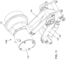
- the pair of wishbone removers 120A, 120B as shown in Figure 10 each comprise a carriage 121 slideably arranged on parallel guide bars 122.
- Each wishbone remover 120A, 120B having a first linear pneumatic actuator 123 for controlling parallel reciprocating movement of the carriage 121 along the guide bars 122.
- a second pneumatic linear actuator 124 via a connecting rod 125 moves a cutting element 126 and gripping elements 127A, 127B inwardly or outwardly along converging guide tracks.
- the cutting and gripping elements 126, 127A, 127B are pivotally mounted on the carriage 121 for being brought into and out of the path of the conveyed poultry parts by a further pneumatic actuator 128.
- these wishbone removers 120A, 120B correspond to the unit described in co-pending application NL 2015436 .
- the breast cutter splitter 130B as shown in Figure 11 comprises a circular double cutter blade 131, driven by a drive motor 132 for cutting along the keel bone of a poultry breast cap.
- the rotating cutter 131 and drive motor 132 are pivotally mounted from a sub-frame 133 by an arm 134 to be elevated into and out of contact with an inverted breast cap suspended from the overhead conveyor. Elevation of the arm 134 is controlled by a pneumatic actuator 135.
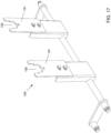
- the pair of staggered front cutters 140A, 140B as shown in Figure 12 are each equipped with opposite centering guides 141 of which only one is visible. These centering guides 141 are movable inwardly and outwardly as controlled by pneumatic actuators 142. Tendon front cutting knifes 143 are movable in and out of the path of movement of a poultry part carrying mandrel, by movement of the pneumatic cylinders 144.
- the pair of staggered first harvesting units 150A, 150B can be activated to be in the path of movement of the poultry breast cap, when an outer fillet is to be separately harvested. Movement in and out of the path of movement is accomplished by a pneumatic actuator 151.
- a pneumatic actuator 151 When controlled to be activated the poultry breast cap is first engaged by scraping blades 152A, 152B, which engage a breast cap between the inner and outer fillets. The harvesting of the outer fillet is then accomplished by outer fillet harvesting grippers 153, which are rotated by drive motors 155.
- Tendon cutter 160B as shown in Figure 14 includes a rotating circular knife 161 driven by a drive motor 162.
- Drive motor 162 is mounted on a pivitable arm 163, which is pivotably mounted on a sub-frame 164 and pivoted by pneumatic actuator 165 to be moved in and out of the breast cap conveying path as required.
- the pair of staggered second harvesting units 170A, 170B serves to harvest half breast fillets and inner fillets.
- the breast fillet is first engaged by opposite guide blocks 171, which can be moved inwardly and outwardly by pneumatic actuators 172. Engagement is then by opposite tunnel plates 173, which are each pivotally mounted from a shaft 174, and urged inwardly by a spring 175. Underneath the tunnel plates 173 is a rotary cutter 176 driven by a motor 177.
- the double third harvesting unit 180 as shown in Figure 16 has carcass guides 181A, 181B for engaging between the carcass and any remaining meat. Underneath the carcass guides 181A, 181B are positioned first and second rollers 182, 183, which are rotated in the direction of the indicated arrows by a drive motor unit 184.
- This third harvesting unit 180 is effective to remove a whole breast cap fillet, when the first and second harvesting units 150A, 150B; 170A, 170B are deactivated.
- the third harvesting unit 180 has no longer any effect and a meatless carcass will simply pass this unit, as there would no longer be any meat left to harvest.
- the carcass unloader 190 has two parallel unloader elements 191, which only allow a carcass carrying mandrel to pass through an upper contoured recess 192. The result is that the carcass is separated from the passing mandrels and will drop down into a collecting container or the like.
- the breast cap carrying mandrels 39 can be rotated through 90 degree increments, and in particular through 180 degrees by similar turning stations, if necessary to improve processing steps such as de-skinning or cutting.
- the method provides for an apparatus (meat processing machine 1) including at least a conveyor (endless conveyor 5) arranged to convey a succession of poultry parts (on first and second carriers 13A, 13B) moving along the path of conveyance downstream of a loading area.
- the meat processing machine is a machine for deboning and filleting breast caps.
- breast cap filleting it can be advantageous to make use of an endless conveyor that defines an upper stretch and a lower stretch extending between first and second redirecting rollers. The upper stretch, or part thereof, can then be used as a loading area.
- the lower stretch conveying the breast cap carriers in an upside-down position can then be used to locate individual meat processing units.
- the described method further includes the step of loading the poultry parts on the conveyor (5) in the loading area, while the conveyor is operated to convey the poultry parts (held on carriers 13A, 13B) in succession.
- the apparatus (1) provided by the method also includes a transfer means (57) in the path of conveyance downstream of the loading area.
- the transfer means (diagonal guide bar 57 for engagement by the guide rollers 27 of the second carriers 13B) is operated to divide the succession of poultry parts into at least two parallel streams.
- the first carriers (13A) are kept aligned in their original track, while the second carriers (13B) are moved over and aligned into another track parallel to the original track.
- the method When coincident with the at least two parallel streams or conveyance tracks the method performs at least two processing steps in a side-by-side arrangement at a downstream location along the path of conveyance.
- the processing steps thereby being effective to process each poultry part either identically or differently, while these are divided into the at least two parallel streams of conveyance.
Landscapes
- Engineering & Computer Science (AREA)
- Life Sciences & Earth Sciences (AREA)
- Wood Science & Technology (AREA)
- Zoology (AREA)
- Food Science & Technology (AREA)
- Mechanical Engineering (AREA)
- Processing Of Meat And Fish (AREA)
Claims (15)
- Verfahren zum Verarbeiten von Geflügelteilen, die sich nacheinander entlang eines Förderweges bewegen, Bereitstellen eines Förderers (5), der eingerichtet ist, um eine Folge von Geflügelteilen entlang des Förderweges stromabwärts von einem Ladebereich zu befördern, Laden der Geflügelteile auf den Förderer (5) in dem Ladebereich, während eines Betriebs des Förderers (5) zur aufeinanderfolgenden Beförderung der Geflügelteile, Bereitstellen eines Übergabemittels (57) in dem Förderweg stromabwärts der Ladebereich, Betätigen der Übergabemittel (57), um die Folge von Geflügelteilen in mindestens zwei parallele Ströme aufzuteilen, gekennzeichnet durch Durchführen von mindestens zwei Verarbeitungsschritten in einer Seite-an-Seite-Anordnung an einem Ort stromabwärts entlang des Förderweges, der mit den mindestens zwei parallelen Strömen zusammenfällt, entweder durch mindestens eine einzelne Verarbeitungseinheit, die in der Lage ist, mindestens zwei Seite-an-Seite-liegende Geflügelteile in den mindestens zwei parallelen Strömen zu verarbeiten, oder durch mindestens zwei identische Verarbeitungseinheiten in einer Seite-an-Seite-Anordnung, und wirksam, um jedes Geflügelteil zu verarbeiten, während die Geflügelteile auf die mindestens zwei parallelen Ströme aufgeteilt und im Wesentlichen gleichmäßig auf die mindestens zwei parallelen Ströme verteilt werden.
- Verfahren nach Anspruch 1, wobei der Förderer (5) als Endlosförderer (5) vorgesehen ist und/oder wobei die Geflügelteile von Trägern (13A, 13B) getragen werden, die mit dem Förderer (5) vorgesehen sind.
- Verfahren nach einem der Ansprüche 1 oder 2, wobei die mindestens zwei Verarbeitungsschritte gleichzeitig durchgeführt werden und/oder wobei die mindestens zwei Verarbeitungsschritte identisch sind.
- Vorrichtung (1) zum Verarbeiten von Geflügelteilen, die sich nacheinander entlang eines Verarbeitungsweges bewegen, wobei die Vorrichtung (1) umfasst: einen Förderer (5), der den Verarbeitungsweg definiert und eingerichtet ist, um eine Folge von Geflügelteilen entlang des Verarbeitungsweges zu befördern, einen Transfermechanismus, der eingerichtet ist, um die Folge von Geflügelteilen in mindestens zwei parallele Ströme aufzuteilen, gekennzeichnet durch Umfassen, stromabwärts des Transfermechanismus, von entweder mindestens einer einzelnen Verarbeitungseinheit, die in der Lage ist, mindestens zwei Seite-an-Seite-liegende Geflügelteile in den mindestens zwei parallelen Strömen zu verarbeiten, oder von mindestens zwei identischen Verarbeitungseinheiten in einer Seite-an-Seite-Anordnung, um mindestens zwei Geflügelteile zu verarbeiten, während die Geflügelteile im Wesentlichen gleichmäßig auf die mindestens zwei parallelen Ströme verteilt werden.
- Vorrichtung (1) nach Anspruch 4, wobei der Förderer (5) ein Endlosförderer (5) ist.
- Vorrichtung (1) nach Anspruch 5, wobei der Endlosförderer (5) eine obere Strecke und eine untere Strecke definiert, die sich zwischen einer ersten und einer zweiten Umlenkrolle (7, 9) erstrecken.
- Vorrichtung (1) nach einem der Ansprüche 4, 5 oder 6, wobei der Förderer (5) ferner eine Vielzahl von ersten und zweiten Trägern (13A, 13B) umfasst, die jeweils ein Geflügelteil tragen.
- Vorrichtung (1) nach einem der Ansprüche 4 bis 7, wobei der Transfermechanismus eine diagonale Führungsstange (57) umfasst, die positioniert ist, um nur mit den zweiten Trägern (13B) in Eingriff zu kommen.
- Vorrichtung (1) nach Anspruch 8, wobei jeder der zweiten Träger (13B) eine vorstehende Führungsrolle (27) zum Eingriff in die diagonale Führungsstange (57) aufweist.
- Vorrichtung (1) nach Anspruch 6, wobei mindestens eine der ersten und zweiten Umlenkrollen (7, 9) des Förderers (5) durch einen Motor (11) angetrieben wird.
- Vorrichtung (1) nach Anspruch 6 oder 10, wobei mindestens eine der ersten und zweiten Umlenkrollen (7, 9) erste und zweite seitliche Räder (43, 45) umfasst.
- Vorrichtung (1) nach Anspruch 11, wobei das erste und das zweite Seitenrad (43, 45) auf einer zentralen Welle (41) montiert sind.
- Vorrichtung (1) nach Anspruch 11, wobei abwechselnd ein erster und ein zweiter Träger (13A, 13B) jeweils auf aufeinanderfolgenden Paaren von ersten und zweiten Querstangen (35, 37) angeordnet sind, die Kettenglieder des Endlosförderers (5) bilden, und wobei die ersten und zweiten seitlichen Räder (43, 45) an ihrem Umfang eingekerbt sind, um mit den Paaren von ersten und zweiten Querstangen (35, 37) in Eingriff zu kommen, die die Kettenglieder des Förderers (5) definieren.
- Vorrichtung (1) nach Anspruch 11, wobei der Transfermechanismus eine diagonale Führungsstange (57) umfasst, die positioniert ist, um nur mit den zweiten Trägern (13B) in Eingriff zu kommen, und wobei die diagonale Führungsstange (57) zwischen den ersten und zweiten seitlichen Rädern (43, 45) von mindestens einer der ersten und zweiten Umlenkrollen (7, 9) positioniert ist.
- Vorrichtung (1) nach einem der Ansprüche 4 bis 14, wobei die Vorrichtung eine Vielzahl von Fleischverarbeitungsstationen zum Verarbeiten von Geflügelteilen umfasst, die im Wesentlichen gleichmäßig über die mindestens zwei parallelen Ströme verteilt sind.
Applications Claiming Priority (2)
| Application Number | Priority Date | Filing Date | Title |
|---|---|---|---|
| NL2017792A NL2017792B1 (en) | 2016-11-15 | 2016-11-15 | Method and apparatus for processing poultry parts moving in succession along a path |
| PCT/NL2017/050734 WO2018093250A1 (en) | 2016-11-15 | 2017-11-14 | Method and apparatus for processing poultry parts moving in succession along a path |
Publications (3)
| Publication Number | Publication Date |
|---|---|
| EP3541190A1 EP3541190A1 (de) | 2019-09-25 |
| EP3541190B1 true EP3541190B1 (de) | 2024-06-12 |
| EP3541190C0 EP3541190C0 (de) | 2024-06-12 |
Family
ID=58402099
Family Applications (1)
| Application Number | Title | Priority Date | Filing Date |
|---|---|---|---|
| EP17817235.9A Active EP3541190B1 (de) | 2016-11-15 | 2017-11-14 | Verfahren und vorrichtung zur verarbeitung von sich nacheinander entlang eines weges bewegenden geflügelteilen |
Country Status (9)
| Country | Link |
|---|---|
| US (1) | US10765122B2 (de) |
| EP (1) | EP3541190B1 (de) |
| JP (1) | JP7229166B2 (de) |
| KR (1) | KR102317890B1 (de) |
| CN (1) | CN110049679B (de) |
| BR (1) | BR112019009890B1 (de) |
| NL (1) | NL2017792B1 (de) |
| PL (1) | PL3541190T3 (de) |
| WO (1) | WO2018093250A1 (de) |
Families Citing this family (4)
| Publication number | Priority date | Publication date | Assignee | Title |
|---|---|---|---|---|
| US10952445B2 (en) * | 2017-01-31 | 2021-03-23 | Foodmate, B.V. | Method and apparatus for continuously harvesting surrounding meat from a successive plurality animal legs |
| BR112022017683A2 (pt) | 2020-03-04 | 2022-11-16 | Foodmate Us Llc | Método e aparelho para remover pele de partes animais |
| US12219965B2 (en) | 2020-11-27 | 2025-02-11 | Ace Specialties, Inc. | Automated chicken deboner system and method |
| CN114524256B (zh) * | 2022-04-25 | 2022-07-08 | 李艳红 | 一种与农业技术装备配套的输送装置 |
Citations (6)
| Publication number | Priority date | Publication date | Assignee | Title |
|---|---|---|---|---|
| EP0168865B1 (de) | 1984-07-06 | 1987-12-23 | Pieter Meyn | Verfahren und Vorrichtung zum Entfernen von Geflügelbrustfleisch |
| DE4008719A1 (de) | 1990-03-19 | 1991-09-26 | Nordischer Maschinenbau | Verfahren zum filetieren von gefluegelkoerpern |
| US7695354B2 (en) | 2004-09-01 | 2010-04-13 | American Seafoods Company, Llc | Fish processing machine with alignment devices and methods for realigning fish during processing |
| WO2013032327A1 (en) | 2011-09-01 | 2013-03-07 | Marel Stork Poultry Processing B.V. | Method and installation for processing slaughtered poultry |
| WO2015117668A1 (de) | 2014-02-07 | 2015-08-13 | Linco Food Systems A/S | Positioniervorrichtung zum positionieren von in förderrichtung längs einer förderstrecke in reihe geförderten geflügelbeinen sowie das positionieren umfassendes verfahren zum entfernen des oberschenkelfleisches von geflügelbeinen |
| EP3075256A1 (de) | 2015-03-25 | 2016-10-05 | Meyn Food Processing Technology B.V. | Verarbeitungs- und/oder inspektionslinie für an den beinen aufgehängtes geflügel |
Family Cites Families (22)
| Publication number | Priority date | Publication date | Assignee | Title |
|---|---|---|---|---|
| US3559233A (en) * | 1969-04-24 | 1971-02-02 | Gary J Bottomley | Method and apparatus for eviscerating poultry |
| CA954660A (en) * | 1970-10-05 | 1974-09-17 | Larry D. Wilson | Method and apparatus for eviscerating poultry |
| US5057055A (en) * | 1990-05-14 | 1991-10-15 | D M P Industries Inc. | Sausage link handling and packaging machine |
| IS4255A (is) * | 1995-06-09 | 1997-03-20 | Style - R.M. Magnusson | Aðferð og búnaður til stærðarflokkunar fisks og annarra efna, lífrænna og ólífrænna, sem henta til þykktarflokkunar |
| US5927465A (en) * | 1996-10-08 | 1999-07-27 | Mannesmann Dematic Rapistan Corp. | Conveyor sortation system with parallel divert |
| US5896809A (en) * | 1997-06-26 | 1999-04-27 | Dec International, Inc. | Food processing system with automatic unloading and optional rack-off |
| WO2000007913A1 (en) * | 1998-08-03 | 2000-02-17 | Kabushiki Kaisha Kajitsu Hihakai Hinshitsu Kenkyujo | Transfer and sorting conveyor |
| EP1211944B1 (de) * | 1999-08-27 | 2004-09-29 | K.J. Maskinfabriken A/S | Anschaubasiertes, automatisches zerteilungssystem |
| EP1351577B1 (de) * | 2001-01-16 | 2006-06-07 | Scanvaegt International A/S | Zuschneidetisch |
| WO2004057969A1 (en) * | 2002-12-31 | 2004-07-15 | Stork Pmt B.V. | Converting a fluctuating stream of poultry into a uniform stream of poultry |
| WO2008043370A1 (de) * | 2006-10-06 | 2008-04-17 | Nordischer Maschinenbau Rud. Baader Gmbh + Co.Kg | Verfahren und vorrichtung zum bearbeiten von in mehrzahl entlang einer bearbeitungslinie geförderten fisch-, geflügel- oder anderes fleischprodukten |
| US7467996B1 (en) * | 2008-04-08 | 2008-12-23 | Jager Todd G | Meat processing conveyor system |
| KR101013933B1 (ko) * | 2008-12-18 | 2011-02-14 | 주식회사 푸디노에프앤디 | 닭 자동 절단 장치 |
| NL2002992C2 (en) * | 2009-06-10 | 2010-12-13 | Foodmate B V | Method and apparatus for automatic meat processing. |
| EP2667728B1 (de) * | 2011-01-26 | 2015-07-29 | Foodmate B.V. | Verfahren zum entbeinen von tierschenkeln zur trennung und entnahme von fleisch daraus und vorrichtung zur durchführung des verfahrens |
| JP5623352B2 (ja) * | 2011-07-13 | 2014-11-12 | 株式会社前川製作所 | 胸側骨格の分離方法及び装置 |
| NL2009717C2 (en) * | 2012-10-29 | 2014-05-01 | Foodmate B V | Method of and system for automatically removing meat from an animal extremity. |
| DK2967090T3 (da) * | 2013-03-15 | 2021-01-04 | Linco Food Systems As | Bærerindretning til fjerkræforarbejdningsindretning |
| NL2011161C2 (en) * | 2013-07-12 | 2015-01-13 | Meyn Food Proc Technology Bv | Poultry processing line comprising a series of poultry carriers and a processing unit or processing units. |
| US9078453B2 (en) | 2013-11-01 | 2015-07-14 | Foodmate B.V. | Method and system for automatically deboning poultry breast caps containing meat and a skeletal structure to obtain breast fillets therefrom |
| PL3062620T3 (pl) * | 2013-11-01 | 2018-08-31 | Foodmate B.V. | Sposób i układ do automatycznego odkostniania drobiowych piersi zawierających mięso i kostną strukturę, aby uzyskać z nich filety z piersi |
| NL2014512B1 (en) * | 2015-03-24 | 2017-01-19 | Meyn Food Proc Technology Bv | Apparatus for mechanically processing an organ or organs taken out from slaughtered poultry. |
-
2016
- 2016-11-15 NL NL2017792A patent/NL2017792B1/nl active
-
2017
- 2017-11-14 EP EP17817235.9A patent/EP3541190B1/de active Active
- 2017-11-14 JP JP2019547065A patent/JP7229166B2/ja active Active
- 2017-11-14 KR KR1020197011403A patent/KR102317890B1/ko active Active
- 2017-11-14 CN CN201780067346.5A patent/CN110049679B/zh active Active
- 2017-11-14 US US16/343,600 patent/US10765122B2/en active Active
- 2017-11-14 WO PCT/NL2017/050734 patent/WO2018093250A1/en not_active Ceased
- 2017-11-14 BR BR112019009890-9A patent/BR112019009890B1/pt active IP Right Grant
- 2017-11-14 PL PL17817235.9T patent/PL3541190T3/pl unknown
Patent Citations (6)
| Publication number | Priority date | Publication date | Assignee | Title |
|---|---|---|---|---|
| EP0168865B1 (de) | 1984-07-06 | 1987-12-23 | Pieter Meyn | Verfahren und Vorrichtung zum Entfernen von Geflügelbrustfleisch |
| DE4008719A1 (de) | 1990-03-19 | 1991-09-26 | Nordischer Maschinenbau | Verfahren zum filetieren von gefluegelkoerpern |
| US7695354B2 (en) | 2004-09-01 | 2010-04-13 | American Seafoods Company, Llc | Fish processing machine with alignment devices and methods for realigning fish during processing |
| WO2013032327A1 (en) | 2011-09-01 | 2013-03-07 | Marel Stork Poultry Processing B.V. | Method and installation for processing slaughtered poultry |
| WO2015117668A1 (de) | 2014-02-07 | 2015-08-13 | Linco Food Systems A/S | Positioniervorrichtung zum positionieren von in förderrichtung längs einer förderstrecke in reihe geförderten geflügelbeinen sowie das positionieren umfassendes verfahren zum entfernen des oberschenkelfleisches von geflügelbeinen |
| EP3075256A1 (de) | 2015-03-25 | 2016-10-05 | Meyn Food Processing Technology B.V. | Verarbeitungs- und/oder inspektionslinie für an den beinen aufgehängtes geflügel |
Also Published As
| Publication number | Publication date |
|---|---|
| JP7229166B2 (ja) | 2023-02-27 |
| US20200060298A1 (en) | 2020-02-27 |
| CN110049679A (zh) | 2019-07-23 |
| NL2017792B1 (en) | 2018-06-01 |
| BR112019009890A2 (pt) | 2019-08-13 |
| US10765122B2 (en) | 2020-09-08 |
| KR102317890B1 (ko) | 2021-10-27 |
| KR20190080866A (ko) | 2019-07-08 |
| BR112019009890B1 (pt) | 2023-11-07 |
| JP2020513250A (ja) | 2020-05-14 |
| PL3541190T3 (pl) | 2024-09-30 |
| WO2018093250A1 (en) | 2018-05-24 |
| EP3541190A1 (de) | 2019-09-25 |
| CN110049679B (zh) | 2021-10-12 |
| EP3541190C0 (de) | 2024-06-12 |
Similar Documents
| Publication | Publication Date | Title |
|---|---|---|
| EP3541190B1 (de) | Verfahren und vorrichtung zur verarbeitung von sich nacheinander entlang eines weges bewegenden geflügelteilen | |
| US9974317B2 (en) | Method of deboning animal thighs for separating and collecting meat therefrom and apparatus for performing the method | |
| NL2008729C2 (en) | A method and apparatus for processing a poultry carcass part. | |
| KR102354113B1 (ko) | 깃털이 제거된 가금류의 다리 전체 또는 다리부위 제품으로부터 껍질의 제거를 위한 시스템, 방법, 및 회전식 장치 | |
| EP3062620B1 (de) | Verfahren und system zum automatischen entbeinen von geflügelbrustkappen mit fleisch und einer skelettstruktur zur gewinnung von brustfilets daraus | |
| US4811457A (en) | Deboning machine | |
| EP1205111A1 (de) | Apparat zum Überführen von Schlachtgeflügel | |
| ATE122849T1 (de) | Einstellbares system zum filettieren von geflügelbrust. | |
| CA2938143A1 (en) | Positioning device for positioning poultry legs conveyed in single file in the conveying direction along a conveyor section and method comprising said positioning for removing the thigh meat from poultry legs | |
| CA2702819A1 (en) | Device for separating filets from the spinal column of beheaded, slaughtered fish with open abdominal cavity by cutting the bridge left by abdominal and back blades around the spinal column and filleting machine comprising such a device | |
| US20150272142A1 (en) | Method and system for automatically deboning poultry breast caps containing meat and a skeletal structure to obtain breast fillets therefrom | |
| JP6875414B2 (ja) | 屠殺された家禽の胴体部の竜骨の少なくとも一部から胸肉を分離するためのシステム | |
| WO2018217090A1 (en) | Cutting unit for cutting meat parts from suspended previously eviscerated poultry carcasses | |
| JP4437757B2 (ja) | 枝肉の解体脱骨方法及び解体脱骨システム | |
| NL2011718C2 (en) | Method and system for automatically deboning poultry breast caps containing meat and a skeletal structure to obtain breast fillets therefrom. | |
| NL2006074C2 (en) | Method of deboning animal thighs for separating and collecting meat therefrom and apparatus for performing the method. | |
| NL2007711C2 (en) | Method of deboning animal thighs for separating and collecting meat there from and apparatus for performing the method. | |
| WO2022229248A2 (en) | A machine for filleting fish | |
| NL8300276A (nl) | Werkwijze en inrichting voor het in delen snijden van geslachte kuikens. | |
| NL8204221A (nl) | Werkwijze en inrichting voor het in delen snijden van geslachte kuikens. |
Legal Events
| Date | Code | Title | Description |
|---|---|---|---|
| STAA | Information on the status of an ep patent application or granted ep patent |
Free format text: STATUS: UNKNOWN |
|
| STAA | Information on the status of an ep patent application or granted ep patent |
Free format text: STATUS: THE INTERNATIONAL PUBLICATION HAS BEEN MADE |
|
| PUAI | Public reference made under article 153(3) epc to a published international application that has entered the european phase |
Free format text: ORIGINAL CODE: 0009012 |
|
| STAA | Information on the status of an ep patent application or granted ep patent |
Free format text: STATUS: REQUEST FOR EXAMINATION WAS MADE |
|
| 17P | Request for examination filed |
Effective date: 20190522 |
|
| AK | Designated contracting states |
Kind code of ref document: A1 Designated state(s): AL AT BE BG CH CY CZ DE DK EE ES FI FR GB GR HR HU IE IS IT LI LT LU LV MC MK MT NL NO PL PT RO RS SE SI SK SM TR |
|
| AX | Request for extension of the european patent |
Extension state: BA ME |
|
| DAV | Request for validation of the european patent (deleted) | ||
| DAX | Request for extension of the european patent (deleted) | ||
| STAA | Information on the status of an ep patent application or granted ep patent |
Free format text: STATUS: EXAMINATION IS IN PROGRESS |
|
| 17Q | First examination report despatched |
Effective date: 20230227 |
|
| GRAP | Despatch of communication of intention to grant a patent |
Free format text: ORIGINAL CODE: EPIDOSNIGR1 |
|
| STAA | Information on the status of an ep patent application or granted ep patent |
Free format text: STATUS: GRANT OF PATENT IS INTENDED |
|
| INTG | Intention to grant announced |
Effective date: 20240108 |
|
| GRAS | Grant fee paid |
Free format text: ORIGINAL CODE: EPIDOSNIGR3 |
|
| GRAA | (expected) grant |
Free format text: ORIGINAL CODE: 0009210 |
|
| STAA | Information on the status of an ep patent application or granted ep patent |
Free format text: STATUS: THE PATENT HAS BEEN GRANTED |
|
| AK | Designated contracting states |
Kind code of ref document: B1 Designated state(s): AL AT BE BG CH CY CZ DE DK EE ES FI FR GB GR HR HU IE IS IT LI LT LU LV MC MK MT NL NO PL PT RO RS SE SI SK SM TR |
|
| REG | Reference to a national code |
Ref country code: GB Ref legal event code: FG4D |
|
| REG | Reference to a national code |
Ref country code: CH Ref legal event code: EP |
|
| REG | Reference to a national code |
Ref country code: IE Ref legal event code: FG4D |
|
| REG | Reference to a national code |
Ref country code: DE Ref legal event code: R096 Ref document number: 602017082564 Country of ref document: DE |
|
| U01 | Request for unitary effect filed |
Effective date: 20240704 |
|
| U07 | Unitary effect registered |
Designated state(s): AT BE BG DE DK EE FI FR IT LT LU LV MT NL PT RO SE SI Effective date: 20240902 |
|
| PG25 | Lapsed in a contracting state [announced via postgrant information from national office to epo] |
Ref country code: HR Free format text: LAPSE BECAUSE OF FAILURE TO SUBMIT A TRANSLATION OF THE DESCRIPTION OR TO PAY THE FEE WITHIN THE PRESCRIBED TIME-LIMIT Effective date: 20240612 |
|
| PG25 | Lapsed in a contracting state [announced via postgrant information from national office to epo] |
Ref country code: GR Free format text: LAPSE BECAUSE OF FAILURE TO SUBMIT A TRANSLATION OF THE DESCRIPTION OR TO PAY THE FEE WITHIN THE PRESCRIBED TIME-LIMIT Effective date: 20240913 |
|
| PG25 | Lapsed in a contracting state [announced via postgrant information from national office to epo] |
Ref country code: ES Free format text: LAPSE BECAUSE OF FAILURE TO SUBMIT A TRANSLATION OF THE DESCRIPTION OR TO PAY THE FEE WITHIN THE PRESCRIBED TIME-LIMIT Effective date: 20240612 |
|
| PG25 | Lapsed in a contracting state [announced via postgrant information from national office to epo] |
Ref country code: NO Free format text: LAPSE BECAUSE OF FAILURE TO SUBMIT A TRANSLATION OF THE DESCRIPTION OR TO PAY THE FEE WITHIN THE PRESCRIBED TIME-LIMIT Effective date: 20240912 Ref country code: HR Free format text: LAPSE BECAUSE OF FAILURE TO SUBMIT A TRANSLATION OF THE DESCRIPTION OR TO PAY THE FEE WITHIN THE PRESCRIBED TIME-LIMIT Effective date: 20240612 Ref country code: GR Free format text: LAPSE BECAUSE OF FAILURE TO SUBMIT A TRANSLATION OF THE DESCRIPTION OR TO PAY THE FEE WITHIN THE PRESCRIBED TIME-LIMIT Effective date: 20240913 Ref country code: ES Free format text: LAPSE BECAUSE OF FAILURE TO SUBMIT A TRANSLATION OF THE DESCRIPTION OR TO PAY THE FEE WITHIN THE PRESCRIBED TIME-LIMIT Effective date: 20240612 Ref country code: RS Free format text: LAPSE BECAUSE OF FAILURE TO SUBMIT A TRANSLATION OF THE DESCRIPTION OR TO PAY THE FEE WITHIN THE PRESCRIBED TIME-LIMIT Effective date: 20240912 |
|
| U20 | Renewal fee for the european patent with unitary effect paid |
Year of fee payment: 8 Effective date: 20241022 |
|
| PG25 | Lapsed in a contracting state [announced via postgrant information from national office to epo] |
Ref country code: IS Free format text: LAPSE BECAUSE OF FAILURE TO SUBMIT A TRANSLATION OF THE DESCRIPTION OR TO PAY THE FEE WITHIN THE PRESCRIBED TIME-LIMIT Effective date: 20241012 |
|
| PG25 | Lapsed in a contracting state [announced via postgrant information from national office to epo] |
Ref country code: CZ Free format text: LAPSE BECAUSE OF FAILURE TO SUBMIT A TRANSLATION OF THE DESCRIPTION OR TO PAY THE FEE WITHIN THE PRESCRIBED TIME-LIMIT Effective date: 20240612 |
|
| PG25 | Lapsed in a contracting state [announced via postgrant information from national office to epo] |
Ref country code: SK Free format text: LAPSE BECAUSE OF FAILURE TO SUBMIT A TRANSLATION OF THE DESCRIPTION OR TO PAY THE FEE WITHIN THE PRESCRIBED TIME-LIMIT Effective date: 20240612 |
|
| PG25 | Lapsed in a contracting state [announced via postgrant information from national office to epo] |
Ref country code: SM Free format text: LAPSE BECAUSE OF FAILURE TO SUBMIT A TRANSLATION OF THE DESCRIPTION OR TO PAY THE FEE WITHIN THE PRESCRIBED TIME-LIMIT Effective date: 20240612 |
|
| PG25 | Lapsed in a contracting state [announced via postgrant information from national office to epo] |
Ref country code: SM Free format text: LAPSE BECAUSE OF FAILURE TO SUBMIT A TRANSLATION OF THE DESCRIPTION OR TO PAY THE FEE WITHIN THE PRESCRIBED TIME-LIMIT Effective date: 20240612 Ref country code: SK Free format text: LAPSE BECAUSE OF FAILURE TO SUBMIT A TRANSLATION OF THE DESCRIPTION OR TO PAY THE FEE WITHIN THE PRESCRIBED TIME-LIMIT Effective date: 20240612 Ref country code: IS Free format text: LAPSE BECAUSE OF FAILURE TO SUBMIT A TRANSLATION OF THE DESCRIPTION OR TO PAY THE FEE WITHIN THE PRESCRIBED TIME-LIMIT Effective date: 20241012 Ref country code: CZ Free format text: LAPSE BECAUSE OF FAILURE TO SUBMIT A TRANSLATION OF THE DESCRIPTION OR TO PAY THE FEE WITHIN THE PRESCRIBED TIME-LIMIT Effective date: 20240612 |
|
| REG | Reference to a national code |
Ref country code: DE Ref legal event code: R026 Ref document number: 602017082564 Country of ref document: DE |
|
| PLBI | Opposition filed |
Free format text: ORIGINAL CODE: 0009260 |
|
| PLAF | Information modified related to communication of a notice of opposition and request to file observations + time limit |
Free format text: ORIGINAL CODE: EPIDOSCOBS2 |
|
| PLAX | Notice of opposition and request to file observation + time limit sent |
Free format text: ORIGINAL CODE: EPIDOSNOBS2 |
|
| 26 | Opposition filed |
Opponent name: BAADER POULTRY HOLDING GMBH Effective date: 20250307 |
|
| REG | Reference to a national code |
Ref country code: CH Ref legal event code: PL |
|
| PG25 | Lapsed in a contracting state [announced via postgrant information from national office to epo] |
Ref country code: MC Free format text: LAPSE BECAUSE OF FAILURE TO SUBMIT A TRANSLATION OF THE DESCRIPTION OR TO PAY THE FEE WITHIN THE PRESCRIBED TIME-LIMIT Effective date: 20240612 |
|
| REG | Reference to a national code |
Ref country code: CH Ref legal event code: PL |
|
| PG25 | Lapsed in a contracting state [announced via postgrant information from national office to epo] |
Ref country code: CH Free format text: LAPSE BECAUSE OF NON-PAYMENT OF DUE FEES Effective date: 20241130 |
|
| PLBB | Reply of patent proprietor to notice(s) of opposition received |
Free format text: ORIGINAL CODE: EPIDOSNOBS3 |
|
| PG25 | Lapsed in a contracting state [announced via postgrant information from national office to epo] |
Ref country code: IE Free format text: LAPSE BECAUSE OF NON-PAYMENT OF DUE FEES Effective date: 20241114 |
|
| U20 | Renewal fee for the european patent with unitary effect paid |
Year of fee payment: 9 Effective date: 20251127 |
|
| PGFP | Annual fee paid to national office [announced via postgrant information from national office to epo] |
Ref country code: GB Payment date: 20251121 Year of fee payment: 9 |
|
| PGFP | Annual fee paid to national office [announced via postgrant information from national office to epo] |
Ref country code: PL Payment date: 20251022 Year of fee payment: 9 |
|
| PG25 | Lapsed in a contracting state [announced via postgrant information from national office to epo] |
Ref country code: HU Free format text: LAPSE BECAUSE OF FAILURE TO SUBMIT A TRANSLATION OF THE DESCRIPTION OR TO PAY THE FEE WITHIN THE PRESCRIBED TIME-LIMIT; INVALID AB INITIO Effective date: 20171114 |
|
| PG25 | Lapsed in a contracting state [announced via postgrant information from national office to epo] |
Ref country code: CY Free format text: LAPSE BECAUSE OF FAILURE TO SUBMIT A TRANSLATION OF THE DESCRIPTION OR TO PAY THE FEE WITHIN THE PRESCRIBED TIME-LIMIT; INVALID AB INITIO Effective date: 20171114 |