EP3543014A1 - Appareil de fenêtre mobile et dispositif d'estampage à chaud de feuilles comprenant l'appareil - Google Patents
Appareil de fenêtre mobile et dispositif d'estampage à chaud de feuilles comprenant l'appareil Download PDFInfo
- Publication number
- EP3543014A1 EP3543014A1 EP19020113.7A EP19020113A EP3543014A1 EP 3543014 A1 EP3543014 A1 EP 3543014A1 EP 19020113 A EP19020113 A EP 19020113A EP 3543014 A1 EP3543014 A1 EP 3543014A1
- Authority
- EP
- European Patent Office
- Prior art keywords
- window
- window portion
- mobile
- actuating means
- stamping device
- Prior art date
- Legal status (The legal status is an assumption and is not a legal conclusion. Google has not performed a legal analysis and makes no representation as to the accuracy of the status listed.)
- Withdrawn
Links
Images


Classifications
-
- B—PERFORMING OPERATIONS; TRANSPORTING
- B41—PRINTING; LINING MACHINES; TYPEWRITERS; STAMPS
- B41F—PRINTING MACHINES OR PRESSES
- B41F13/00—Common details of rotary presses or machines
- B41F13/0024—Frames
-
- B—PERFORMING OPERATIONS; TRANSPORTING
- B41—PRINTING; LINING MACHINES; TYPEWRITERS; STAMPS
- B41F—PRINTING MACHINES OR PRESSES
- B41F16/00—Transfer printing apparatus
- B41F16/0006—Transfer printing apparatus for printing from an inked or preprinted foil or band
- B41F16/004—Presses of the reciprocating type
- B41F16/0046—Presses of the reciprocating type with means for applying print under heat and pressure, e.g. using heat activable adhesive
-
- B—PERFORMING OPERATIONS; TRANSPORTING
- B41—PRINTING; LINING MACHINES; TYPEWRITERS; STAMPS
- B41F—PRINTING MACHINES OR PRESSES
- B41F1/00—Platen presses, i.e. presses in which printing is effected by at least one essentially-flat pressure-applying member co-operating with a flat type-bed
- B41F1/26—Details
- B41F1/60—Safety devices
-
- B—PERFORMING OPERATIONS; TRANSPORTING
- B41—PRINTING; LINING MACHINES; TYPEWRITERS; STAMPS
- B41F—PRINTING MACHINES OR PRESSES
- B41F16/00—Transfer printing apparatus
-
- B—PERFORMING OPERATIONS; TRANSPORTING
- B41—PRINTING; LINING MACHINES; TYPEWRITERS; STAMPS
- B41F—PRINTING MACHINES OR PRESSES
- B41F19/00—Apparatus or machines for carrying out printing operations combined with other operations
- B41F19/02—Apparatus or machines for carrying out printing operations combined with other operations with embossing
- B41F19/06—Printing and embossing between a negative and a positive forme after inking and wiping the negative forme; Printing from an ink band treated with colour or "gold"
-
- B—PERFORMING OPERATIONS; TRANSPORTING
- B41—PRINTING; LINING MACHINES; TYPEWRITERS; STAMPS
- B41F—PRINTING MACHINES OR PRESSES
- B41F33/00—Indicating, counting, warning, control or safety devices
- B41F33/0018—Protection means against injury to the operator
-
- B—PERFORMING OPERATIONS; TRANSPORTING
- B41—PRINTING; LINING MACHINES; TYPEWRITERS; STAMPS
- B41J—TYPEWRITERS; SELECTIVE PRINTING MECHANISMS, i.e. MECHANISMS PRINTING OTHERWISE THAN FROM A FORME; CORRECTION OF TYPOGRAPHICAL ERRORS
- B41J29/00—Details of, or accessories for, typewriters or selective printing mechanisms not otherwise provided for
- B41J29/12—Guards, shields or dust excluders
-
- B—PERFORMING OPERATIONS; TRANSPORTING
- B44—DECORATIVE ARTS
- B44B—MACHINES, APPARATUS OR TOOLS FOR ARTISTIC WORK, e.g. FOR SCULPTURING, GUILLOCHING, CARVING, BRANDING, INLAYING
- B44B5/00—Machines or apparatus for embossing decorations or marks, e.g. embossing coins
- B44B5/0052—Machines or apparatus for embossing decorations or marks, e.g. embossing coins by pressing
-
- B—PERFORMING OPERATIONS; TRANSPORTING
- B41—PRINTING; LINING MACHINES; TYPEWRITERS; STAMPS
- B41K—STAMPS; STAMPING OR NUMBERING APPARATUS OR DEVICES
- B41K3/00—Apparatus for stamping articles having integral means for supporting the articles to be stamped
- B41K3/62—Details or accessories
- B41K3/66—Safety devices, e.g. for preventing extraction of copy matter before completion of stamping operation
-
- B—PERFORMING OPERATIONS; TRANSPORTING
- B41—PRINTING; LINING MACHINES; TYPEWRITERS; STAMPS
- B41P—INDEXING SCHEME RELATING TO PRINTING, LINING MACHINES, TYPEWRITERS, AND TO STAMPS
- B41P2219/00—Printing presses using a heated printing foil
-
- B—PERFORMING OPERATIONS; TRANSPORTING
- B41—PRINTING; LINING MACHINES; TYPEWRITERS; STAMPS
- B41P—INDEXING SCHEME RELATING TO PRINTING, LINING MACHINES, TYPEWRITERS, AND TO STAMPS
- B41P2233/00—Arrangements for the operation of printing presses
- B41P2233/20—Safety devices preventing damage
Definitions
- This invention relates to the field of packaging and printing, in particular to a hot foil stamping device with a mobile window apparatus.
- the conventional hot stamping device includes a transparent window, which can be opened for loading and unloading the molded board. During usage of the hot foil stamping device, the window is closed, so that an operation space is isolated from outside, which plays a protective role.
- foil-conveying modes in a hot foil stamping device There are two foil-conveying modes in a hot foil stamping device: a horizontal foil conveying mode and a longitudinal foil conveying mode. An operator of the device can choose a suitable mode according to requirements of production.
- the window when the longitudinal foil conveying mode is selected, the window can be completely closed so as to provide a reliable protection.
- the window of the existing hot foil stamping device is moved upwardly to closed to a lower surface of the foil, and thus, a large open area is left above an upper surface of the foil, which renders a potential risk during production, and foreign objects may easily enter the operation area of the hot foil stamping device, which may impair a hot stamping quality.
- a mobile window apparatus for a hot foil stamping device comprising: at least one first window portion, the first window portion movable in a first direction; at least one second window portion movable in a second direction different from the first direction; and an actuating means configured to move the first window and the second window, respectively; wherein said actuating means moves said first window portion and said second window portion between a closed position and an open position, in said open position, said first window portion and said second window portion being spaced apart from each other to form an access opening, and in said closed position, the first window portion and the second window portion are close to each other so as to substantially shield the access opening and to keep a gap between the first window portion and the second window portion for passing through a sheet material for processed.
- the mobile window apparatus is provided with a stop, which abuts against at least one of the first window portion and the second window portion so as to keep the gap for passing through a sheet material for processed.
- the stop is provided on one of the first window portion and the second window portion.
- the second window portion is located below the first window portion, the first window portion moves in the first direction vertically upward and the second window portion moves in the second direction vertically downward.
- the actuating means comprises: an actuator connected to one of the first window and the second window; and a linkage mechanism connected between the first window and the second window.
- the actuator comprises at least one of a pneumatic cylinder, a hydraulic means and a motor.
- the linkage mechanism comprises at least one of a cable, a pulley, a link mechanism and a sliding member.
- the actuating means comprises: an actuating cylinder connected to the first window; a cable having a first end connected to the first window and a second end connected to the second window; and a pulley around which the cable surrounds.
- the linkage mechanism includes two sets of cables and pulleys, each of the set is provided at one longitudinal side of opposite sides of the first window portion and the second window portion.
- the present invention also provides with a hot foil stamping device comprising the mobile window apparatus as above described, wherein the sheet material is a foil material, which is conveyed in a horizontal foil conveying mode.
- the window portions can substantially shield the access opening with only the small size of the gap is left, it is possible to avoid the presence of an opening area with potential safety hazard and improve the safety of the device when the horizontal foil conveying is used.
- the preferred embodiment of the present invention employs a single actuating cylinder and a linkage mechanism comprised of cables and pulleys that are simple in construction and highly reliable in operation.
- FIG. 1 is a schematic illustration of a hot foil stamping device with a mobile window apparatus 10 according to the invention, in which the foil material is conveyed with a horizontal foil conveying mode, i.e., the foil material passes horizontally between upper and lower platens and passes through a gap 8 between a first window portion 1 and a second window portion 2 of the mobile window apparatus 10.
- a horizontal foil conveying mode i.e., the foil material passes horizontally between upper and lower platens and passes through a gap 8 between a first window portion 1 and a second window portion 2 of the mobile window apparatus 10.
- the mobile window apparatus 10 comprises a first window portion 1 and a second window portion 2, both of which are movable.
- first window portion 1 and the second window portion 2 are rectangular, which have similar size and shape, the first window portion 1 and the second window portion 2 are stacked, and the first window portion 1 is disposed above the second window portion 2, that is, a lower frame of the first window portion 1 is disposed above an upper frame of the second window.
- the number and shape of the first window portion 1 and the second window portion 2 are not limited to the illustrated examples.
- the size of two windows may be set according to a height of the foil conveyed horizontally.
- Each of the window portions 1 and 2 generally has an outer frame and a transparent window supported by the outer frame for observing operation of the hot foil stamping device.
- the mobile window apparatus 10 further includes an actuating means configured to move the first window portion 1 and the second window portion 2, respectively.
- the actuating means can at least move the first window portion 1 and the second window portion 2 between a closed position and an open position.
- the open position the first window portion 1 and the second window portion 2 are spaced apart from each other for form an access opening, through which the operator can assemble and disassemble the upper and lower platens 9 in the device.
- a size of the opening can be modified depending on the devices.
- the closed position the first window portion 1 and the second window portion 2 are close to each other to substantially shield the access opening while keep a gap 8 between the first window portion 1 and the second window portion 2 for passing through the foil material.
- the gap 8 is sized below 10cm, preferably, it is sized in a range of 1-2cm, and most preferably, it is sized in a range of 0.5-1cm, its size ensures that the foil material 3 can pass, but the user's hand or foreign matter cannot easily enter. As shown in FIG. 2A , the gap 8 is horizontal and extends along an entire length of the horizontal sides of the rectangular first window portion 1 and second window portion 2.
- a stop 7 as gap-keeping means is provided on the second window portion 2 according to the preferred embodiment of the invention.
- the stops 7 may be disposed on both ends of the lower frame of the first window portion 1.
- the stop 7 can for example be made of a cushioning material such as rubber.
- the stop 7 may also be formed on a portion of a body of the hot foil stamping device that engages with the frame of the window.
- the stop 7 is preferably detachable, which not only facilitates replacement of the stop 7 if it is damaged, but also allows the size of the gap 8 between the two window portions to be changed by replacing a stop 7 having a different size.
- the actuating means of the mobile window apparatus 10 is preferentially configured such that the two windows portions 1 and 2 move synchronously in different directions.
- the two windows portions 1 and 2 are moved along the opposite vertical directions as shown in arrow A in Fig. 2A , wherein the upper first window portion 1 is moved vertically upward while the second lower window portion 2 is moved vertically downward, so as to gradually enlarge the size of the gap 8 .
- the actuating means may include an actuator connected to one of the first window portion 1 and the second window portion 2; and a linkage mechanism connected between the first window portion 1 and the second window portion 2.
- the actuator may comprise at least one of a pneumatic cylinder 4, a hydraulic means, a motor and a handle, and the linkage mechanism may comprise at least one of a cable 6, a pulley 5, a connecting rod and a sliding member.
- the actuating means may also comprise two actuators, which are respectively coupled to the first window portion 1 and the second window portion 2, both actuators are able to move the window portions 1 and 2 synchronously with a controller in the hot foil stamping device.
- the actuating means comprises an actuating cylinder 4 connected to the first window portion 1.
- the cylinder 4 is located above the center of the upper side of the first window portion 1, and an actuating rod of the cylinder 4 protrudes downwardly and is fixed to the upper side of the first window portion 1.
- the linkage mechanism in the actuating means comprises a pulley 5 around which the cable 6 surrounds.
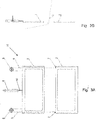
- FIGS. 2A and 3A there are two sets of cables 6 and pulleys 5, respectively, on opposite longitudinal sides of the window.
- the pulleys 5 are located above the first window portion 1 and are substantially at the same height.
- the cable 6 bypasses the pulley 5, one end of the cable 6 is connected to the first window portion 1, and the other end of the cable 6 is connected to the second window portion 2.
- the first window portion 1 When the cylinder 4 is actuated to retract the actuating rod, the first window portion 1 is pulled up vertically. When the actuating rod is fully retracted into a cylinder body of the cylinder 4, the first window portion 1 stops into its open position. With the movement of the first window portion 1,the second window portion 2 connected to the first window portion 1 by the cable 6 moves in the opposite vertical downward direction due to its gravity, and when the first window portion 1 stops into its open position, the second window portion 2 also stops into its open position, as shown in FIGS. 3A and 3B .
- the mobile window apparatus 10 also has other modification.
- the movement of the first window portion 1 and the second window portion 2 are not limited to the above embodiment.
- the first window portion 1 and the second window portion 2 may also be opened by rotation.
- the first window portion 1 is pivoted on both sides of the upper frame, the lower frame of the first window portion 1 is rotated upwardly to open, and a pivoting shaft of the second window portion 2 is provision on both sides of its lower frame, the lower frame of the first window portion 1 is rotated downwardly to open, so that the access opening will be formed.
- the actuating means can also adopt other forms.
- the actuating means for rotating the window portions can adopt a rotary electric motor.
- the two window portions are operated by two independent actuators, each of which comprise at least one of a pneumatic cylinder, a hydraulic means, a motor and a handle.
- the linkage mechanism may be provided on a connecting rod mechanism or a rack-and-pinion mechanism connected between the two window portions, and when one of the window portions is actuated by the actuating cylinder 4, the other of the window portion is moved in a different direction synchronously by means of the connecting rod mechanism or the rack-and-pinion mechanism.
- the window portions can substantially shield the access opening with only the small size of the gap 8 is left, it is possible to avoid the presence of an opening area with potential safety hazard and improve the safety of the device when the horizontal foil conveying is used.
- the above mobile window apparatus 10 is described as an example provided in the hot foil stamping device. For reasons, such a mobile window apparatus 10 is also applicable to other packaging devices that need to pass a sheet material through the window portion.
- the preferred embodiment of the present invention employs a single actuating cylinder 4 and a linkage mechanism comprised of cables and pulleys that are simple in construction and highly reliable in operation.
Landscapes
- Engineering & Computer Science (AREA)
- Mechanical Engineering (AREA)
- Power-Operated Mechanisms For Wings (AREA)
- Labeling Devices (AREA)
- Inking, Control Or Cleaning Of Printing Machines (AREA)
Applications Claiming Priority (1)
| Application Number | Priority Date | Filing Date | Title |
|---|---|---|---|
| CN201810239926.4A CN110293747B (zh) | 2018-03-22 | 2018-03-22 | 开窗装置及具有开窗装置的烫金设备 |
Publications (1)
| Publication Number | Publication Date |
|---|---|
| EP3543014A1 true EP3543014A1 (fr) | 2019-09-25 |
Family
ID=65954989
Family Applications (1)
| Application Number | Title | Priority Date | Filing Date |
|---|---|---|---|
| EP19020113.7A Withdrawn EP3543014A1 (fr) | 2018-03-22 | 2019-03-08 | Appareil de fenêtre mobile et dispositif d'estampage à chaud de feuilles comprenant l'appareil |
Country Status (4)
| Country | Link |
|---|---|
| US (1) | US11052651B2 (fr) |
| EP (1) | EP3543014A1 (fr) |
| CN (1) | CN110293747B (fr) |
| TW (1) | TWI727280B (fr) |
Citations (2)
| Publication number | Priority date | Publication date | Assignee | Title |
|---|---|---|---|---|
| US5704292A (en) * | 1995-04-28 | 1998-01-06 | Bobst Sa | Belt transport arrangement for a machine transferring images onto sheets from the belts |
| US20130174752A1 (en) * | 2010-09-16 | 2013-07-11 | Frédéric Badoux | Foil guiding device for stamping machine |
Family Cites Families (23)
| Publication number | Priority date | Publication date | Assignee | Title |
|---|---|---|---|---|
| US2488257A (en) * | 1945-04-21 | 1949-11-15 | Ciba Pharm Prod Inc | Safety door of the biparting type |
| NL7018980A (fr) * | 1970-12-29 | 1972-07-03 | J J T Rompa | |
| JPH0760595A (ja) * | 1993-08-31 | 1995-03-07 | Nippei Toyama Corp | トランスファマシンにおけるカバー装置 |
| DE4408026A1 (de) * | 1994-03-10 | 1995-09-14 | Koenig & Bauer Ag | Druckwerk für eine Mehrfarbenrollenrotationsdruckmaschine |
| US7162835B1 (en) * | 1998-12-01 | 2007-01-16 | Tokyo Seimitsu, Co., Ltd | Gravity safety door for an apparatus for manufacturing or inspecting semiconductors |
| US6968645B2 (en) * | 2000-10-04 | 2005-11-29 | Quikserv Corporation | Sliding service window |
| JP4954595B2 (ja) * | 2005-04-20 | 2012-06-20 | ハイデルベルガー ドルツクマシーネン アクチエンゲゼルシヤフト | 印刷機を運転する方法 |
| CN201154576Y (zh) * | 2008-01-24 | 2008-11-26 | 江崇刚 | 微型手动烫金机 |
| EP2141027A1 (fr) * | 2008-07-03 | 2010-01-06 | Kba-Giori S.A. | Procédé et installation pour l'application d'un matériau en feuille sur des feuilles successives |
| DE102009046069A1 (de) * | 2009-10-28 | 2011-05-12 | Manroland Ag | Fördersystem für eine Rotationsdruckmaschine |
| CN102441815A (zh) * | 2011-10-09 | 2012-05-09 | 上海三一精机有限公司 | 一种防护门装置及加工中心 |
| US8955270B2 (en) * | 2012-05-16 | 2015-02-17 | Olmos Scofield, Llc | Window assemblies including bronze elements |
| DE102012223402A1 (de) * | 2012-12-17 | 2014-06-18 | Krones Ag | Direktdruckmaschine mit Verkleidung |
| KR20140139659A (ko) * | 2013-05-27 | 2014-12-08 | 두산인프라코어 주식회사 | 도어 안전 시스템을 구비한 공작 기계용 커버 |
| JP2016028837A (ja) * | 2014-07-25 | 2016-03-03 | ファナック株式会社 | 工作機械のスライドドア |
| US20160136944A1 (en) * | 2014-11-18 | 2016-05-19 | Collar Central, Llc | Method and apparatus for imprinting collars |
| CN204526372U (zh) * | 2014-12-31 | 2015-08-05 | 博斯特(上海)有限公司 | 一种烫金机金箔收紧导板 |
| CN206012015U (zh) * | 2016-08-31 | 2017-03-15 | 瑞安市飞鹏机械厂 | 快速换版机构 |
| CN106425674A (zh) * | 2016-11-29 | 2017-02-22 | 无锡特恒科技有限公司 | 防护门装置 |
| CN206426642U (zh) * | 2016-12-23 | 2017-08-22 | 郑州华美彩印纸品有限公司 | 一种具有剪裁机构的烫金机 |
| CN206733798U (zh) * | 2017-04-21 | 2017-12-12 | 东台世恒机械科技有限公司 | 一种烫金机用输纸定位机构 |
| CN206735349U (zh) * | 2017-04-25 | 2017-12-12 | 湖南工程学院 | 广告照明放置箱 |
| CN107756132A (zh) * | 2017-11-01 | 2018-03-06 | 江南数控机床有限公司 | 一种加工中心左右推拉窗结构 |
-
2018
- 2018-03-22 CN CN201810239926.4A patent/CN110293747B/zh not_active Expired - Fee Related
-
2019
- 2019-03-08 EP EP19020113.7A patent/EP3543014A1/fr not_active Withdrawn
- 2019-03-15 TW TW108108861A patent/TWI727280B/zh not_active IP Right Cessation
- 2019-03-21 US US16/360,227 patent/US11052651B2/en not_active Expired - Fee Related
Patent Citations (2)
| Publication number | Priority date | Publication date | Assignee | Title |
|---|---|---|---|---|
| US5704292A (en) * | 1995-04-28 | 1998-01-06 | Bobst Sa | Belt transport arrangement for a machine transferring images onto sheets from the belts |
| US20130174752A1 (en) * | 2010-09-16 | 2013-07-11 | Frédéric Badoux | Foil guiding device for stamping machine |
Also Published As
| Publication number | Publication date |
|---|---|
| CN110293747B (zh) | 2022-05-20 |
| CN110293747A (zh) | 2019-10-01 |
| US20190291489A1 (en) | 2019-09-26 |
| TW201940350A (zh) | 2019-10-16 |
| US11052651B2 (en) | 2021-07-06 |
| TWI727280B (zh) | 2021-05-11 |
Similar Documents
| Publication | Publication Date | Title |
|---|---|---|
| EP2977175B1 (fr) | Machine de soufflage de bouteilles présentant un mécanisme de levage et de serrage de la matrice de fond | |
| EP2977174B1 (fr) | Mécanisme de liaison entre ouverture et fermeture de matrice uniaxiale et levage de matrice inférieure | |
| KR101962056B1 (ko) | 혼련기 | |
| KR101690098B1 (ko) | 유리패널 이송장치 | |
| KR101861581B1 (ko) | 알루미늄 압출재의 이송장치 | |
| US10232600B2 (en) | Film peeling machine movement assembly | |
| EP3543014A1 (fr) | Appareil de fenêtre mobile et dispositif d'estampage à chaud de feuilles comprenant l'appareil | |
| ITTV20130153A1 (it) | Macchina per il taglio di prodotti in lastra, dispositivo di protezione e metodo operativo | |
| EP2977181B1 (fr) | Système avec mécanisme de levage de matrice inférieure | |
| JP5802836B2 (ja) | エレベーター装置 | |
| CN104925554B (zh) | 用于退绕片材卷的退绕设备 | |
| CN113500901A (zh) | 驾驶室及作业机械 | |
| ITMI971982A1 (it) | Macchina per la produzione di pannelli di lamiera con bordi piegati | |
| KR20190027145A (ko) | 고소작업차량의 리프트장치 | |
| JP4761915B2 (ja) | 箱体の封函装置 | |
| CN106583585A (zh) | 一种出料机构 | |
| CN213010457U (zh) | 一种高弹抗撕裂片材生产用冷却输送带 | |
| WO2014031740A2 (fr) | Appareil et procédé pour convoyeur à décalage | |
| KR101504313B1 (ko) | 금형반전 및 개폐기 | |
| KR101024585B1 (ko) | 선재 조압연기용 안전장치 | |
| KR20110052040A (ko) | 트리퍼의 빈 커버 개폐장치 | |
| CN205634133U (zh) | 自动换盒机的引线框气动防撞推杆机构 | |
| JP6282953B2 (ja) | ローカバー保持装置 | |
| CN210555900U (zh) | 一种全自动开装站 | |
| JP2007007689A (ja) | プレス装置 |
Legal Events
| Date | Code | Title | Description |
|---|---|---|---|
| PUAI | Public reference made under article 153(3) epc to a published international application that has entered the european phase |
Free format text: ORIGINAL CODE: 0009012 |
|
| STAA | Information on the status of an ep patent application or granted ep patent |
Free format text: STATUS: THE APPLICATION HAS BEEN PUBLISHED |
|
| AK | Designated contracting states |
Kind code of ref document: A1 Designated state(s): AL AT BE BG CH CY CZ DE DK EE ES FI FR GB GR HR HU IE IS IT LI LT LU LV MC MK MT NL NO PL PT RO RS SE SI SK SM TR |
|
| AX | Request for extension of the european patent |
Extension state: BA ME |
|
| STAA | Information on the status of an ep patent application or granted ep patent |
Free format text: STATUS: REQUEST FOR EXAMINATION WAS MADE |
|
| 17P | Request for examination filed |
Effective date: 20200709 |
|
| RBV | Designated contracting states (corrected) |
Designated state(s): AL AT BE BG CH CY CZ DE DK EE ES FI FR GB GR HR HU IE IS IT LI LT LU LV MC MK MT NL NO PL PT RO RS SE SI SK SM TR |
|
| STAA | Information on the status of an ep patent application or granted ep patent |
Free format text: STATUS: EXAMINATION IS IN PROGRESS |
|
| 17Q | First examination report despatched |
Effective date: 20220103 |
|
| STAA | Information on the status of an ep patent application or granted ep patent |
Free format text: STATUS: THE APPLICATION IS DEEMED TO BE WITHDRAWN |
|
| 18D | Application deemed to be withdrawn |
Effective date: 20251001 |